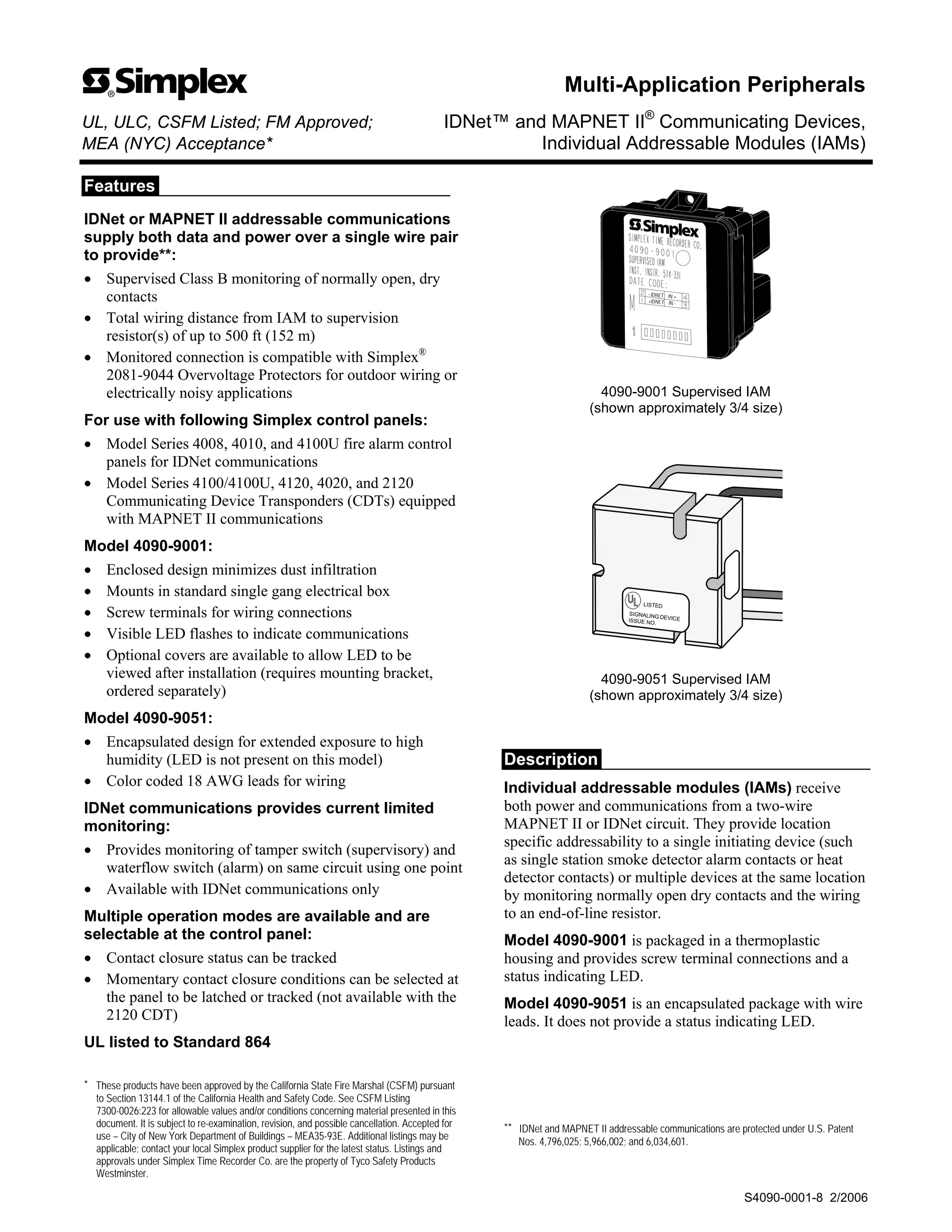
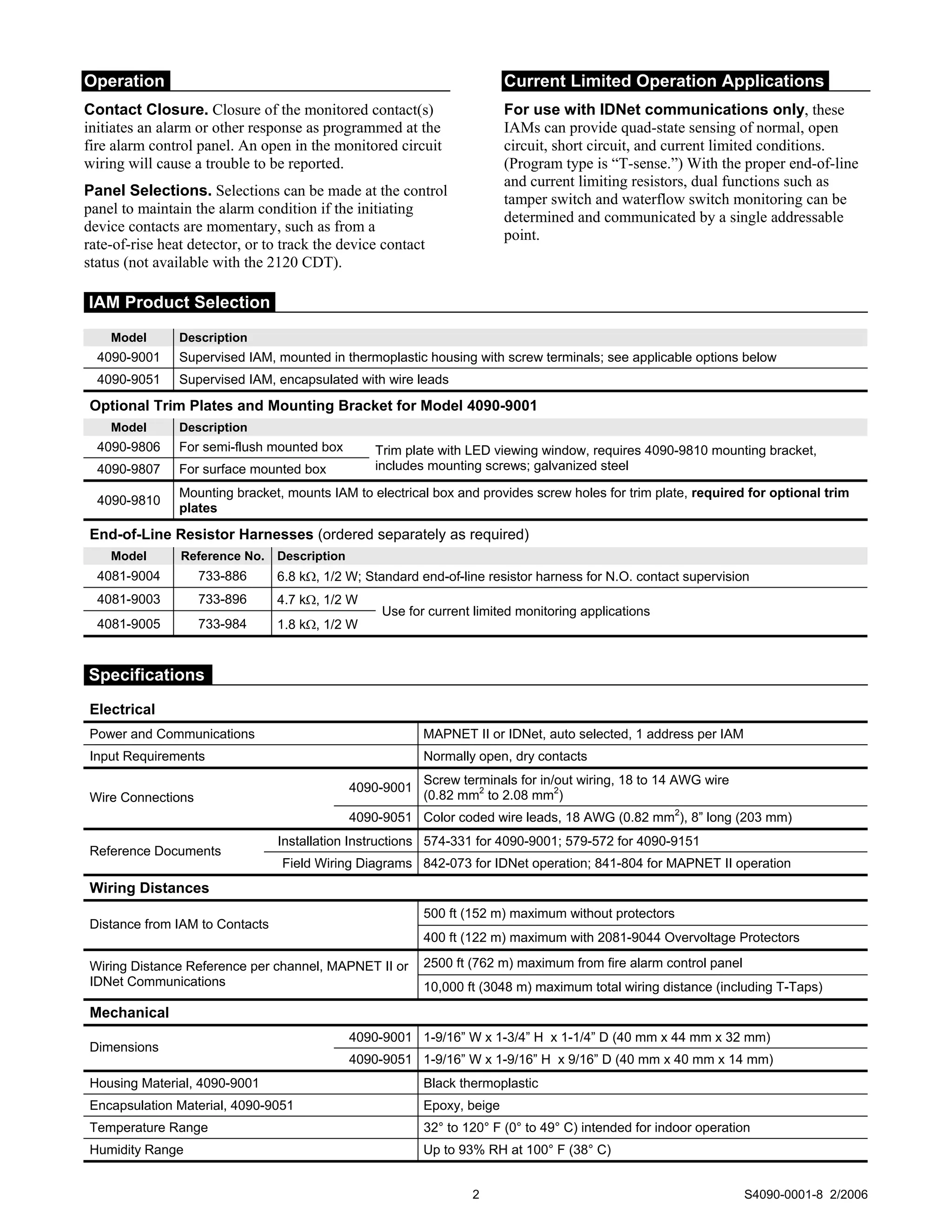
1. Features
IDNet or MAPNET II addressable communications
supply both data and power over a single wire pair
to provide**:
• Supervised Class B monitoring of normally open, dry
contacts
• Total wiring distance from IAM to supervision
resistor(s) of up to 500 ft (152 m)
• Monitored connection is compatible with Simplex®
2081-9044 Overvoltage Protectors for outdoor wiring or
electrically noisy applications
For use with following Simplex control panels:
• Model Series 4008, 4010, and 4100U fire alarm control
panels for IDNet communications
• Model Series 4100/4100U, 4120, 4020, and 2120
Communicating Device Transponders (CDTs) equipped
with MAPNET II communications
Model 4090-9001:
• Enclosed design minimizes dust infiltration
• Mounts in standard single gang electrical box
• Screw terminals for wiring connections
• Visible LED flashes to indicate communications
• Optional covers are available to allow LED to be
viewed after installation (requires mounting bracket,
ordered separately)
Model 4090-9051:
• Encapsulated design for extended exposure to high
humidity (LED is not present on this model)
• Color coded 18 AWG leads for wiring
IDNet communications provides current limited
monitoring:
• Provides monitoring of tamper switch (supervisory) and
waterflow switch (alarm) on same circuit using one point
• Available with IDNet communications only
Multiple operation modes are available and are
selectable at the control panel:
• Contact closure status can be tracked
• Momentary contact closure conditions can be selected at
the panel to be latched or tracked (not available with the
2120 CDT)
UL listed to Standard 864
* These products have been approved by the California State Fire Marshal (CSFM) pursuant
to Section 13144.1 of the California Health and Safety Code. See CSFM Listing
7300-0026:223 for allowable values and/or conditions concerning material presented in this
document. It is subject to re-examination, revision, and possible cancellation. Accepted for
use – City of New York Department of Buildings – MEA35-93E. Additional listings may be
applicable; contact your local Simplex product supplier for the latest status. Listings and
approvals under Simplex Time Recorder Co. are the property of Tyco Safety Products
Westminster.
- IDNET IN +
+IDNET IN -
4090-9001 Supervised IAM
(shown approximately 3/4 size)
LISTED
SIGNALING DEVICE
ISSUE NO.
4090-9051 Supervised IAM
(shown approximately 3/4 size)
Description
Individual addressable modules (IAMs) receive
both power and communications from a two-wire
MAPNET II or IDNet circuit. They provide location
specific addressability to a single initiating device (such
as single station smoke detector alarm contacts or heat
detector contacts) or multiple devices at the same location
by monitoring normally open dry contacts and the wiring
to an end-of-line resistor.
Model 4090-9001 is packaged in a thermoplastic
housing and provides screw terminal connections and a
status indicating LED.
Model 4090-9051 is an encapsulated package with wire
leads. It does not provide a status indicating LED.
** IDNet and MAPNET II addressable communications are protected under U.S. Patent
Nos. 4,796,025; 5,966,002; and 6,034,601.
Multi-Application Peripherals
UL, ULC, CSFM Listed; FM Approved; IDNet™ and MAPNET II®
Communicating Devices,
MEA (NYC) Acceptance* Individual Addressable Modules (IAMs)
S4090-0001-8 2/2006
2. Operation
Contact Closure. Closure of the monitored contact(s)
initiates an alarm or other response as programmed at the
fire alarm control panel. An open in the monitored circuit
wiring will cause a trouble to be reported.
Panel Selections. Selections can be made at the control
panel to maintain the alarm condition if the initiating
device contacts are momentary, such as from a
rate-of-rise heat detector, or to track the device contact
status (not available with the 2120 CDT).
Current Limited Operation Applications
For use with IDNet communications only, these
IAMs can provide quad-state sensing of normal, open
circuit, short circuit, and current limited conditions.
(Program type is “T-sense.”) With the proper end-of-line
and current limiting resistors, dual functions such as
tamper switch and waterflow switch monitoring can be
determined and communicated by a single addressable
point.
Model Description
4090-9001 Supervised IAM, mounted in thermoplastic housing with screw terminals; see applicable options below
4090-9051 Supervised IAM, encapsulated with wire leads
Optional Trim Plates and Mounting Bracket for Model 4090-9001
Model Description
4090-9806 For semi-flush mounted box
4090-9807 For surface mounted box
Trim plate with LED viewing window, requires 4090-9810 mounting bracket,
includes mounting screws; galvanized steel
4090-9810
Mounting bracket, mounts IAM to electrical box and provides screw holes for trim plate, required for optional trim
plates
End-of-Line Resistor Harnesses (ordered separately as required)
Model Reference No. Description
4081-9004 733-886 6.8 kΩ, 1/2 W; Standard end-of-line resistor harness for N.O. contact supervision
4081-9003 733-896 4.7 kΩ, 1/2 W
4081-9005 733-984 1.8 kΩ, 1/2 W
Use for current limited monitoring applications
Electrical
Power and Communications MAPNET II or IDNet, auto selected, 1 address per IAM
Input Requirements Normally open, dry contacts
4090-9001
Screw terminals for in/out wiring, 18 to 14 AWG wire
(0.82 mm2
to 2.08 mm2
)
Wire Connections
4090-9051 Color coded wire leads, 18 AWG (0.82 mm2
), 8” long (203 mm)
Installation Instructions 574-331 for 4090-9001; 579-572 for 4090-9151
Reference Documents
Field Wiring Diagrams 842-073 for IDNet operation; 841-804 for MAPNET II operation
Wiring Distances
500 ft (152 m) maximum without protectors
Distance from IAM to Contacts
400 ft (122 m) maximum with 2081-9044 Overvoltage Protectors
2500 ft (762 m) maximum from fire alarm control panel
Wiring Distance Reference per channel, MAPNET II or
IDNet Communications 10,000 ft (3048 m) maximum total wiring distance (including T-Taps)
Mechanical
4090-9001 1-9/16” W x 1-3/4” H x 1-1/4” D (40 mm x 44 mm x 32 mm)
Dimensions
4090-9051 1-9/16” W x 1-9/16” H x 9/16” D (40 mm x 40 mm x 14 mm)
Housing Material, 4090-9001 Black thermoplastic
Encapsulation Material, 4090-9051 Epoxy, beige
Temperature Range 32° to 120° F (0° to 49° C) intended for indoor operation
Humidity Range Up to 93% RH at 100° F (38° C)
2 S4090-0001-8 2/2006
IAM Product Selection
Specifications
3. Optional Trim Plates and Mounting Bracket for Visible LED
Single gang electrical
box 2-1/2" (64mm)
minimum depth
(supplied by others)
Single gang blank cover plate and mounting screws, for use when
LED is not required to be externally viewed (supplied by others)
4090-9001 IDNet
supervised IAM
Field wiring shown
for reference
Address setting under resealable label
- IDNET IN +
+IDNET IN -
LED viewing port
4090-9806, Trim plate for
semi-flush mounted box
4090-9807, Trim plate for
surface mounted box
4-1/4"
(108 mm)
2-1/2"
(64 mm)
2-13/16"
(72 mm)
4-1/2"
(114 mm)
Light pipe for
LED viewing
NOTE: These mounting plates require mounting bracket 4090-9810.
4090-9810 Mounting
bracket, ordered
separately
Mounting Reference, Single Gang Blank Cover Plate
3 S4090-0001-8 2/2006
Mounting Information