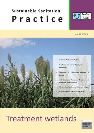
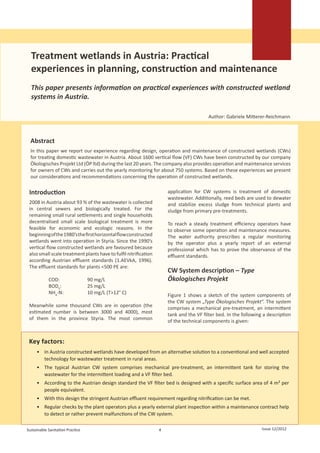
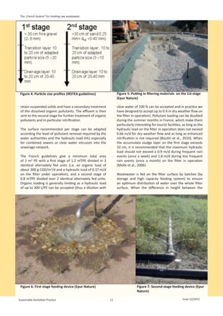
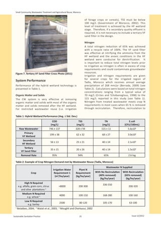
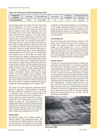
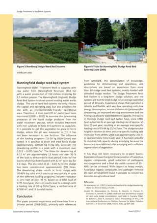
The paper discusses Austria's experience with constructed wetland systems for treating domestic wastewater. It describes the typical Austrian system, which includes mechanical pre-treatment, an intermittent tank, and a vertical flow filter bed designed with a surface area of 4 m2 per person equivalent. Regular monitoring and maintenance by plant operators helps ensure treatment standards are met. Over 1,600 such systems have been constructed in Austria, most including intermittent loading and planted with common reed. Monitoring data shows 90% of samples meet Austria's stringent 10 mg/L NH4-N limit, with 70% below 1 mg/L, demonstrating the systems' ability to achieve nitrification.

![Treatment wetlands in Austria
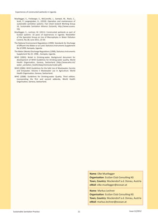
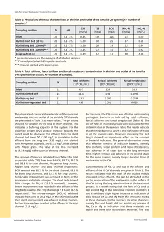
might lead to soil clogging. When it is evident in reduced Conclusion
treatment efficiency it can take a long time until they are
completely restored. Constructed wetlands have developed from an
“alternative green idea” to a conventional and well
The plant owners are instructed about the necessary accepted technology for wastewater treatment in rural
maintenance works and obliged to keep a “maintenance areas of Austria.
book” documenting weekly or monthly controls of
nitrification with a test kit. They also should check To keep a high treatment efficiency and steady operation
the condition of the three chamber septic tank, the the operators have to observe some maintenance works
intermittent feeding system and the even distribution and regular controls of the system components.
through the pipe system in regular intervals.
A regular external examination by a professional helps
Pre treatment to detect problems and recommendations can be given
to the operators. Finally the long term operation is also
The sludge of the pre-treatment has to be emptied
documented in a “plant history” by the company.
in time in order to prevent sludge drift into the reed
beds. The emptying intervals depend on the size of the
pre-treatment system and vary between one year and References
several years. The sludge can be stabilized in a separate 1.AEVkA (1996): 1. Abwasseremissionsverordnung für kommunales
sludge drying reed bed on the spot. Alternatively it Abwasser (Austrian regulation for emissions from domestic
can be transported to a central sewer plant for further wastewater). BGBl.210/1996, Vienna, Austria [in German].
treatment. ÖNORM B 2505 (2009): Bepflanzte Bodenfilter (Pflanzenkläranlagen)
– Anwendung, Bemessung, Bau und Betrieb (Subsurface-flow
constructed wetlands – Application, dimensioning, installation
Intermittent feeding system and operation). Norm, Österreichisches Normungsinstitut, Vienna,
The functioning of the intermittent feeding by the valve Austria [in German].
can be checked by measuring the difference in height in
the well before and after the feeding process. After some
years the rubber part of the flexible pipe can be porous
which is why the wastewater seeps continuously only
into the front part of the filter bed. If this is not detected
the filter will be clogged after some time. This is why the
device should be controlled once a month.
Filter bed
During the first year attention should be paid to the
growing of the plants. Weeds should be removed until
the reed is established.
An uneven distribution of wastewater above the filter
is the most common problem of malfunctioning of
constructed wetlands. It can be measured by collecting
the water flowing out the pipes at the 4 corner points
of the filter bed. The distribution system can be best
adjusted and cleaned after the cutting of the plants.
The cutting of the plants can be made in spring. Some
operators prefer to cut the reed in autumn, lay the dry
straw on the filter surface and remove it in spring because
then there are less small leave parts on the filter surface.
The water level in the filter bed should be as low as
possible.
Name: Gabriele Mitterer-Reichmann
Organisation: Technisches Büro für
Kulturtechnik GmbH
Town, Country: Graz, Austria
eMail: mitterer.oepro@aon.at
Sustainable Sanitation Practice 8 Issue 12/2012](https://image.slidesharecdn.com/ssp-12jul2012-120810142602-phpapp01/85/Ssp-12-jul2012-8-320.jpg)
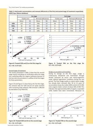
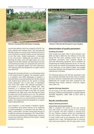
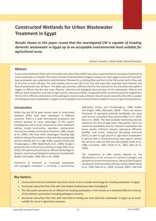
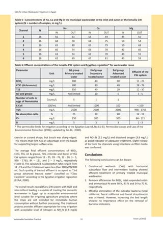
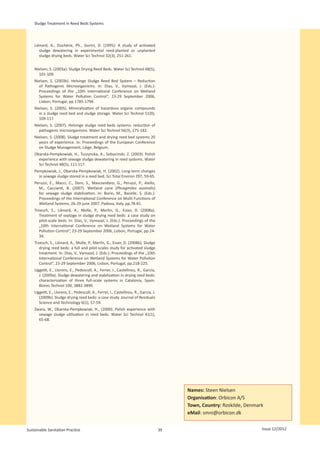
![The „French System“ for treating raw wastewater
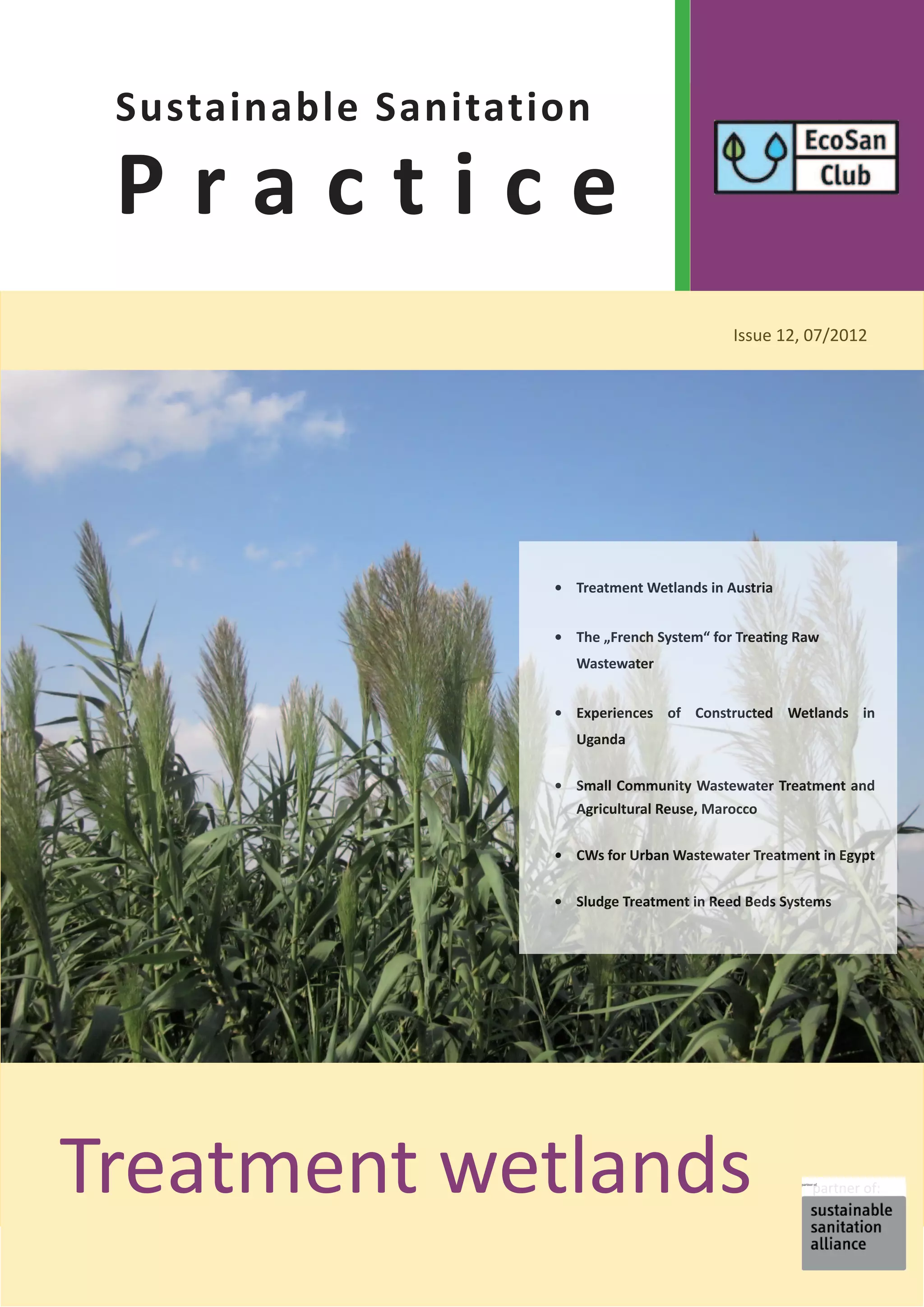
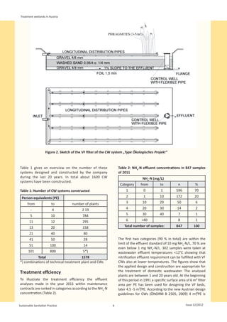
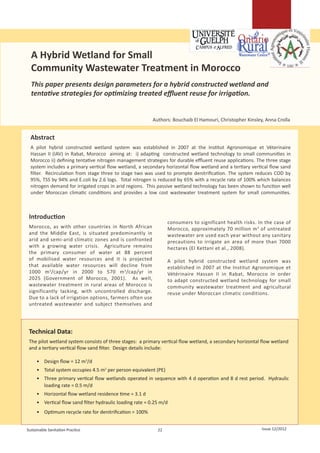
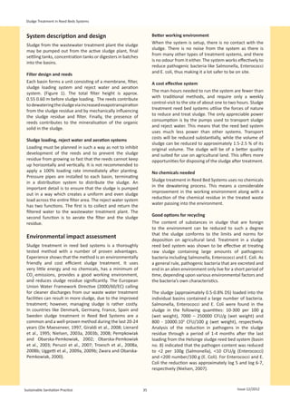
Figure 1: Development of vertical flow CW over time in France (French Ministry Figure 2: Roussillon plant, France
data base) (1250 PE, Epur Nature)
Design and Results configuration and media profile are presented in Figure
3 and Figure 4.
Design
The sizing of VF CWs is still roughly based on organic load After a coarse screening (30 mm) of the raw sewage
acceptance (in terms of active surface area per people wastewater the influent is transferred onto the first
equivalent [PE] - one people equivalent (PE) is defined stage. Each primary stage unit receives the full organic
in France as the following production of pollutants: load during the feeding phase which lasts 3.5 days,
150L/PE/d, 90 g SS/PE/d (combined sewer) or 60 g SS/PE/d before being rested for 7 days. These alternating phases
(separate sewer), 120 g COD/PE/d, 60 g BOD5/PE/d, 15 g of feeding and rest are fundamental in controlling the
TKN/PE/d and 2.2 g TP/PE/d). Current recommendations growth of the attached biomass on the filter media (avoid
are 2 stages of filters with a total active area of 2m²/PE. biological clogging), to maintain aerobic conditions
While the first stage is divided into 3 identical filters, within the filter and to mineralize the sludge deposit
the second is divided into identical two filters. Filter accumulated on the surface. The role of the first stage is to
Figure 3: VF CW configuration with siphon
Sustainable Sanitation Practice 10 Issue 12/2012](https://image.slidesharecdn.com/ssp-12jul2012-120810142602-phpapp01/85/Ssp-12-jul2012-10-320.jpg)
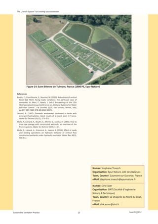
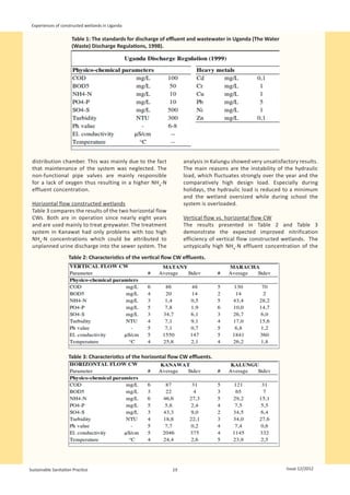
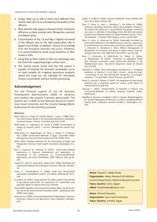
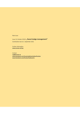
![The „French System“ for treating raw wastewater
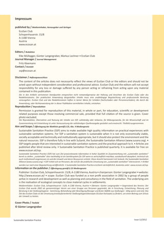
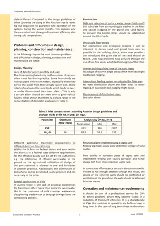
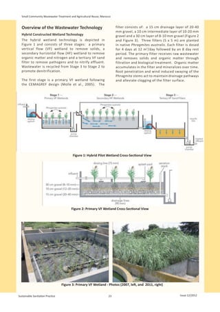
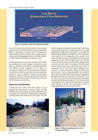
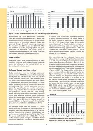
Table 1: Characteristics of the data base plants (70 units, SINT/Epur Nature database)
Age of the Plant (years of Hydraulic load Organic load
operation)
≤3 3 < age < 6 >6 50 % < 50 % < 100 % >100 % < 50 % 50 % < 100 % > 100 %
54 % 40 % 6% 43% 43% 14% 52% 41 % 7%
Table 2: Inlet/outlet concentrations and removal efficiencies of a two stage VF CWs (SINT/Epur Nature database)
Inlet concentration (mg/L) Outlet concentration (mg/L) Removal efficiencies (%)
Mean SD Mean SD Mean SD
COD 651 282 50 29 92 7
BOD5 291 140 8 9 97 3
SS 242 133 8 6 97 3
TKN 56 34 7 12 90 12
TP 7 4 6 3 32 25
inlet and the outlet is sufficient, it is possible to work effluent quality for all parameters except phosphorous
without energy by using a siphon (e.g. Aquasaf siphon, (P-removal is mainly correlated to the phosphate
Figure 2) as feeding device. The water distribution onto adsorption capacity of the filtering materials and not
each stage has a fundamental importance; therefore long-lasting) and denitrification (due to the prevailing
it is recommended to design i) the feeding system for aerobic conditions in the filters).
the first stage to deliver a flow of 0.5 m3/h per square
meter of fed bed surface, with one feeding point for Removal efficiencies of organic pollutants are fairly
a maximum of 50 m² and ii) the feeding system of the constant, (low standard deviation [SD]) while the
second stage to deliver 0.25 m3/h to 0.5 m3/ per square nitrification rate (assumed as the TKN removal) shows
meter, according to the characteristics of the sand, with a 12 % standard deviation and, not surprisingly, SD for
one feeding point for 1 m² of filter surface (Figure 6 and phosphorus is even higher. Varying nitrification rates are
Figure 7). caused by differences between filter materials and also
are correlated to the hydraulic and organic loads.
Concerning the sludge management, with an Finally, the statistical data treatment showed that there
accumulation rate of 1 to 2 cm/year, a free board of 50 is no significant impact of the season on the removal
cm on the first stage ensures its accumulation for about rate of the assessed parameters.
10 years before emptying.
First stage of treatment
The results observed on the first stage are summarized
Global Efficiencies in Table 3. We can clearly observe that the first stage of
Pollutant Removal efficiencies treatment concerns mainly SS, COD and BOD5 removal,
The global removal efficiencies were assessed on although nitrification is not negligible with a mean of
constructed wetlands following the French design for 60 % of TKN removal. The removal efficiency of the first
domestic raw wastewater and were based on a statistical stage is enhanced by the sludge layer deposit which
treatment of a data base of 70 plants built by SINT or regulates the infiltration and the hydraulics of the filter.
Epur Nature. The plants characteristics (age, organic
and hydraulic load) of these plants are summarized As observed in Figure 8 which presents the removal
in Table 1. They all are 2 stages VFCW (with a 2 m²/PE performances in relation the applied load (100 %
design) with 0.4-0.6 m of gravel (2-8 mm) on the first removal represented by the dotted line) the first stage
stage and 0.3 to 0.4 m of sand (0-4 mm) on the second removal efficiencies for COD and SS are linear, even for
stage, fed with raw wastewater loads above 300 g COD/m²/d on the filter in operation,
without clogging. On the other hand, nitrification
removal decreases rapidly with an increasing load as
Table 2 shows the inlet/outlet concentrations and the
showed on Figure 9. This is the result of a higher oxygen
global removal efficiency for plants with a hydraulic
demand induced by concomitant higher organic loads
load lower than 0.9 m/d on the filter in operation on
and lower oxygenation rates due to higher hydraulic
the first stage. The influent is quite variable mainly due
loads.
to the different characteristics of sewerage networks
(combined or separate and amount of clear water
intrusion). Globally the system is able to achieve a good
Sustainable Sanitation Practice 12 Issue 12/2012](https://image.slidesharecdn.com/ssp-12jul2012-120810142602-phpapp01/85/Ssp-12-jul2012-12-320.jpg)

![Small Community Wastewater Treatment and Agricultural Reuse, Marocco
promote denitrification will often be necessary to Technology 51(9), 81-90.
avoid nitrate contamination of the groundwater in Crites, R., Tchobanoglous, G. (1998): Small and Decentralised
arid regions with significant water demand. Wastewater Management Systems. McGraw Hill, Toronto, Canada.
El Hamouri, B. (2007): Subsurface-horizontal flow constructed
wetland for sewage treatment under Moroccan climate conditions.
Pathogens Desalination 215, 153-158.
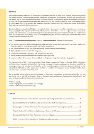
The two pathogen indicators governing wastewater El Kettani, S., Azzouzi, E., Boukachabine, K., El Yamani, M.,
reuse are E.coli bacteria and helminth eggs. E.coli Maata, A., Rajaoui, M. (2008): Intestinal parasitosis and use of
numbers are reduced by 2.6 logs throughout the untreated wastewater for agriculture in Settat, Morocco. Eastern
Mediterranean Health Journal 14(6), 1435-1444.
system from 5.6 x 10 6 in the raw wastewater to
Government of Morocco (2001): Etat de l‘environnement du
1.5 x 10 4 CFU/100mL at the outlet of the VF sand Maroc. Ministère de l‘Aménagement du Territoire, de l‘Eau et de
filter. Although not enumerated in this study, l‘Environnement, Rabat, Morocco [in French].
helminth eggs are effectively removed through Government of Morocco (2002): Directives marocaines pour la
filtration and will likely be removed in the first filter, réutilisation des eaux usées en agriculture. Directive n° 1276-01 du
as they are closely associated with wastewater 10 Chaabane 1423. Ministre de l’Équipement et du Ministre chargé
de l’Aménagement du Territoire, de l’Urbanisme, de l’Habitat et de
sludge (Kengne et al., 2009).
l’Environnement du Maroc, Rabat, Morocco [in French].
Kengne, I.M., Akoa, A., Koné, D. (2009). Recovery of biosolids from
For unrestricted reuse (i.e. irrigation of produce constructed wetlands used of faecal sludge dewatering in tropical
eaten raw) pathogen standards are typically regions. Environmental Science and Technology 43, 6816-6821.
10 3 CFU/100mL E.coli and <1 helminth egg/litre Molle, P., Liénard, A., Boutin, C., Merlin, G., Iwema, A. (2005) How to
(WHO, 2006). A further disinfection step would treat raw sewage with constructed wetlands : An overview of the
therefore be required as the VF Sand Filter reduces French systems. Water Science and Technology 51(9), 11-21.
E.coli to only 1.5 x 10⁴ CFU/100mL. Moughli and Cherkaoui (2002): Programme de réduction des excès
d’azote apportés à la betterave à sucre et au blé dans le périmètre
irrigué du Tadla. Revue HTE No. 123. [in French]
Conclusions Walali, L.D., Skiredj, A., Elattir, H. (2003): Transfert de technologie en
agriculture No. 105, Ministère de l’Agriculture et du Développement
The hybrid constructed wetland technology is a Rural du Maroc, Rabat, Morocco [in French].
promising wastewater treatment alternative for WHO (2006): Guidelines for the Safe Use of Wastewater, Excreta and
small communities in Morocco and for communities Greywater. Volume II. Wastewater Use in Agriculture. World Health
with comparable socio-economic and climatic Organisation, Geneva, Switzerland.
conditions. The system has been shown to function Young, R., White, G., Brown, M., Burton, J., Atkins, B. (Eds.) (1998):
The Constructed Wetlands Manual. Department of Land and Water
well over four years of continuous operation.
Conservation, New South Wales, Australia.
The passive wetland technology provides several
advantages including: low capital and operating
costs, low energy requirements and high levels
of treatment. The system produces tertiary
quality effluent suitable for direct discharge or
for irrigation of forage crops, cereals and fruit
trees while reducing pathogen risk and protecting
groundwater from excess nitrogen leaching. Name: Bouchaib El Hamouri
Organisation: Département Eau
Acknowledgements Environnement et Infrastructures, Institut
Support for this research study was provided by Agronomique et Vétérinaire Hassan II
the Canadian International Development Agency – Town, Country: Rabat, Morocco
University Partnerships in Cooperation and
eMail: belhamouri@gmail.com
Development Program.
Name: Christopher Kinsley
Organisation: Ontario Rural Wastewater
References
Belabbes, K. (2004): Rapport de prestation d’expertise sur le thème Centre, University of Guelph-Campus d’Alfred
Besoins en eau des cultures dans le périmètre du Tadla. Projet Town, Country: Ontario, Canada
d’initiative propre : Ecobilans appliqués à l’agriculture et Formation
de Conseillers agricoles en environnement au Maroc (EFCA-PIP) [in
eMail: ckinsley@alfredc.uoguelph.ca
French].
Berrada, A. (2009): Assessment of Drip Irrigation in Morocco With Name: Anna Crolla
Particular Emphasis on the Plain of Tadla. Limited Technical Organisation: Ontario Rural Wastewater
Bulletin Agricultural Experimental Station LTB09-01. Colorado State
University, USA. Centre, University of Guelph-Campus d’Alfred
Cooper, P. (2005): The Performance of Vertical Flow Constructed Town, Country: Ontario, Canada
Wetland systems with special reference to the significance of eMail: acrolla@alfredc.uoguelph.ca
Oxygen Transfer and Hydraulic Loading Rates. Water Science and
Sustainable Sanitation Practice 26 Issue 12/2012](https://image.slidesharecdn.com/ssp-12jul2012-120810142602-phpapp01/85/Ssp-12-jul2012-26-320.jpg)


![[Duncan_Mara]_Domestic_Wastewater_Treatment_in_Dev(z-lib.org).pdf](https://cdn.slidesharecdn.com/ss_thumbnails/duncanmaradomesticwastewatertreatmentindevz-lib-230720090216-408bdb51-thumbnail.jpg?width=640&height=640&fit=bounds)


![Getting Started with Apache Spark: Big Data Made Simple [Free Meetup]](https://cdn.slidesharecdn.com/ss_thumbnails/apachesparkgettingstarted-260203175547-8361bcc3-thumbnail.jpg?width=640&height=640&fit=bounds)


