SlideShare a Scribd company logo
1 of 12
Download to read offline
SRM University
Autonomous Underwater Vehicle
Concept and Design of AUV Sedna
Website: www.srmauv.com
Akshaya Raj Dayal , Aniket Ray, Abhishek Bansal, Aakash Khurana, Malle Veera Goutham
Abstract-SRM University Autonomous
Underwater Vehicle Team is an
undergraduate team of students that
develop AUVs for competition and
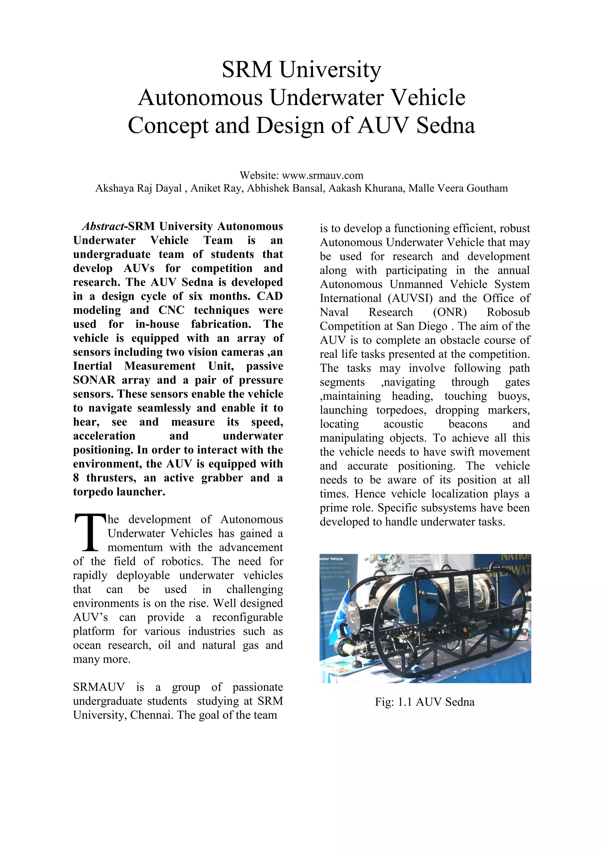
research. The AUV Sedna is developed
in a design cycle of six months. CAD
modeling and CNC techniques were
used for in-house fabrication. The
vehicle is equipped with an array of
sensors including two vision cameras ,an
Inertial Measurement Unit, passive
SONAR array and a pair of pressure
sensors. These sensors enable the vehicle
to navigate seamlessly and enable it to
hear, see and measure its speed,
acceleration and underwater
positioning. In order to interact with the
environment, the AUV is equipped with
8 thrusters, an active grabber and a
torpedo launcher.
he development of Autonomous
Underwater Vehicles has gained a
momentum with the advancement
of the field of robotics. The need for
rapidly deployable underwater vehicles
that can be used in challenging
environments is on the rise. Well designed
AUV’s can provide a reconfigurable
platform for various industries such as
ocean research, oil and natural gas and
many more.
SRMAUV is a group of passionate
undergraduate students studying at SRM
University, Chennai. The goal of the team
is to develop a functioning efficient, robust
Autonomous Underwater Vehicle that may
be used for research and development
along with participating in the annual
Autonomous Unmanned Vehicle System
International (AUVSI) and the Office of
Naval Research (ONR) Robosub
Competition at San Diego . The aim of the
AUV is to complete an obstacle course of
real life tasks presented at the competition.
The tasks may involve following path
segments ,navigating through gates
,maintaining heading, touching buoys,
launching torpedoes, dropping markers,
locating acoustic beacons and
manipulating objects. To achieve all this
the vehicle needs to have swift movement
and accurate positioning. The vehicle
needs to be aware of its position at all
times. Hence vehicle localization plays a
prime role. Specific subsystems have been
developed to handle underwater tasks.
Fig: 1.1 AUV Sedna
T
MECHANICAL DESIGN
A. OVERVIEW
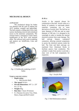
The mechanical design for Sedna
was planned with the goal of making the
AUV modular, compact and lightweight.
The hull contains a sliding deck with a rack
system, facilitating removal and centralized
access to the electronic components. The
external frame is designed to foster future
modification of the AUV with minimal
effort. The software tools used in modeling
and analysis are SolidWorks, Catia and
ANSYS.
Fig: 1.2 Solidworks rendering of AUV
Sedna
VEHICLE SPECIFICATIONS:
• Depth rating :
o 50ft (Acrylic Hull)
• Max speed: 0.6 m/s
• Overall Dimensions: 48" L x 24"
W x 21" H,
• Weight:45kg
• Run time: 1 hours 30 minutes
• 8 x Thrusters for active Yaw, Pitch,
Heave, Surge and Roll Control
B. HULL
Acrylic is the material chosen for
construction of the hull. Acrylic refers to a
family of synthetic or man-made plastic
materials, containing one or more
derivatives of acrylic acid. The hull has an
inner diameter of 290 mm and an outer
diameter of 300 mm. It is designed to be
watertight in order to insulate the internal
electrical systems from water damage. The
hull end-cap features waterproof
connectors, allowing external components
to access the electrical systems inside the
hull. The front and back end-caps are
machined from Aluminum blocks to
facilitate passive heat conduction. The
cylinder is made from acrylic to provide a
clear view of the hull components for
inspection.
Fig: 1 Acrylic Hull
Fig: 2 Hull Deformation analysis
C. EXTERNAL FRAME
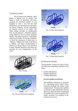
For the frame to be modular, a drill
pattern is applied over its surface. The
frame is made of aluminum and hard-
anodized for structural stability. It was
designed in such a way that the total
deformation, von mission stress and strains
are always minimum. All the components
are directly secured to the frame. The
frame design provides an unobstructed
flow for the thrusters. Structural analysis
using ANSYS is done to ensure structural
rigidity. The frame consists of 2 side plates
made up of Al-6061-T6 having a thickness
of 6mm.The dimension of each plate is
1100mm x 500mm the width of the frame
is 500mm. The frame accommodates 8
thrusters for Surge, Heave, Yaw and Pitch
Control. Handles attached to the frame are
provided for easy transportation of the
AUV.
Fig: 3 Frame
Fig: 4 Frame Deformation analysis
Fig: 5 Frame Stress analysis
Fig: 7 Frame Strain analysis
D. PNEUMATIC SYSTEMS
The pneumatics systems are used to drive
the following manipulators attached to the
frame :
• Grabber Mechanism
• Dropper Mechanism
• Torpedo Mechanism
(i)Active grabber mechanism:
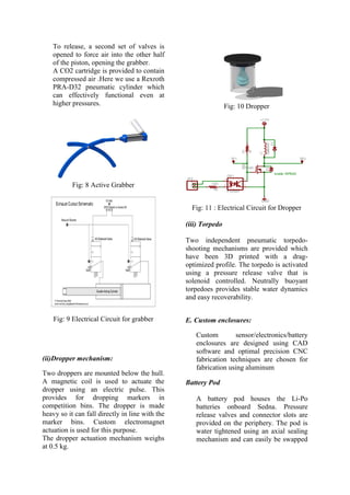
The grabbing mechanism is powered
by a pneumatic piston which allows
controlled grabbing and release using
compressed air. The pneumatic grabber
is utilized to grab underwater mission
objects.To grab, the piston extends and
the grabber arms close around the PVC
object, securing it for transport to the
second recovery area.
To release, a second set of valves is
opened to force air into the other half
of the piston, opening the grabber.
A CO2 cartridge is provided to contain
compressed air .Here we use a Rexroth
PRA-D32 pneumatic cylinder which
can effectively functional even at
higher pressures.
Fig: 8 Active Grabber
Fig: 9 Electrical Circuit for grabber
(ii)Dropper mechanism:
Two droppers are mounted below the hull.
A magnetic coil is used to actuate the
dropper using an electric pulse. This
provides for dropping markers in
competition bins. The dropper is made
heavy so it can fall directly in line with the
marker bins. Custom electromagnet
actuation is used for this purpose.
The dropper actuation mechanism weighs
at 0.5 kg.
Fig: 10 Dropper
Fig: 11 : Electrical Circuit for Dropper
(iii) Torpedo
Two independent pneumatic torpedo-
shooting mechanisms are provided which
have been 3D printed with a drag-
optimized profile. The torpedo is activated
using a pressure release valve that is
solenoid controlled. Neutrally buoyant
torpedoes provides stable water dynamics
and easy recoverability.
E. Custom enclosures:
Custom sensor/electronics/battery
enclosures are designed using CAD
software and optimal precision CNC
fabrication techniques are chosen for
fabrication using aluminum
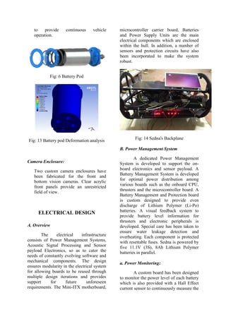
Battery Pod
A battery pod houses the Li-Po
batteries onboard Sedna. Pressure
release valves and connector slots are
provided on the periphery. The pod is
water tightened using an axial sealing
mechanism and can easily be swapped
to provide continuous vehicle
operation.
Fig: 6 Battery Pod
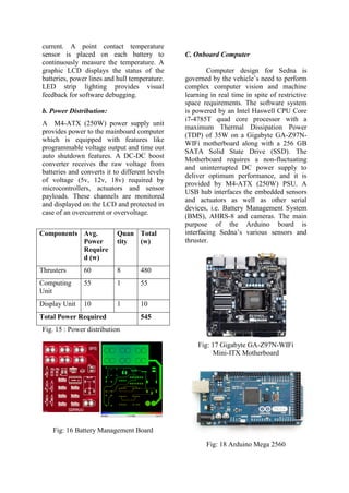
Fig: 13 Battery pod Deformation analysis
Camera Enclosure:
Two custom camera enclosures have
been fabricated for the front and
bottom vision cameras. Clear acrylic
front panels provide an unrestricted
field of view.
ELECTRICAL DESIGN
A. Overview
The electrical infrastructure
consists of Power Management Systems,
Acoustic Signal Processing and Sensor
payload Electronics, so as to cater the
needs of constantly evolving software and
mechanical components. The design
ensures modularity in the electrical system
for allowing boards to be reused through
multiple design iterations and provides
support for future unforeseen
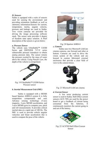
requirements. The Mini-ITX motherboard,
microcontroller carrier board, Batteries
and Power Supply Units are the main
electrical components which are enclosed
within the hull. In addition, a number of
sensors and protection circuits have also
been incorporated to make the system
robust.
Fig: 14 Sedna's Backplane
B. Power Management System
A dedicated Power Management
System is developed to support the on-
board electronics and sensor payload. A
Battery Management System is developed
for optimal power distribution among
various boards such as the onboard CPU,
thrusters and the microcontroller board. A
Battery Management and Protection board
is custom designed to provide even
discharge of Lithium Polymer (Li-Po)
batteries. A visual feedback system to
provide battery level information for
thrusters and electronic peripherals is
developed. Special care has been taken to
ensure water leakage detection and
overheating. Each component is protected
with resettable fuses. Sedna is powered by
five 11.1V (3S), 8Ah Lithium Polymer
batteries in parallel.
a. Power Monitoring:
A custom board has been designed
to monitor the power level of each battery
which is also provided with a Hall Effect
current sensor to continuously measure the
current. A point contact temperature
sensor is placed on each battery to
continuously measure the temperature. A
graphic LCD displays the status of the
batteries, power lines and hull temperature.
LED strip lighting provides visual
feedback for software debugging.
b. Power Distribution:
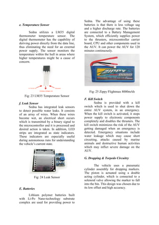
A M4-ATX (250W) power supply unit
provides power to the mainboard computer
which is equipped with features like
programmable voltage output and time out
auto shutdown features. A DC-DC boost
converter receives the raw voltage from
batteries and converts it to different levels
of voltage (5v, 12v, 18v) required by
microcontrollers, actuators and sensor
payloads. These channels are monitored
and displayed on the LCD and protected in
case of an overcurrent or overvoltage.
Components Avg.
Power
Require
d (w)
Quan
tity
Total
(w)
Thrusters 60 8 480
Computing
Unit
55 1 55
Display Unit 10 1 10
Total Power Required 545
Fig. 15 : Power distribution
Fig: 16 Battery Management Board
C. Onboard Computer
Computer design for Sedna is
governed by the vehicle’s need to perform
complex computer vision and machine
learning in real time in spite of restrictive
space requirements. The software system
is powered by an Intel Haswell CPU Core
i7-4785T quad core processor with a
maximum Thermal Dissipation Power
(TDP) of 35W on a Gigabyte GA-Z97N-
WIFi motherboard along with a 256 GB
SATA Solid State Drive (SSD). The
Motherboard requires a non-fluctuating
and uninterrupted DC power supply to
deliver optimum performance, and it is
provided by M4-ATX (250W) PSU. A
USB hub interfaces the embedded sensors
and actuators as well as other serial
devices, i.e. Battery Management System
(BMS), AHRS-8 and cameras. The main
purpose of the Arduino board is
interfacing Sedna’s various sensors and
thruster.
Fig: 17 Gigabyte GA-Z97N-WIFi
Mini-ITX Motherboard
Fig: 18 Arduino Mega 2560
D. Sensors
Sedna is equipped with a suite of sensors
used for sensing the environment and
providing orientation feedback as well as
odometry information.Sensors for current,
temperature, inertia, angular velocity,
pressure and leakage are used in Sedna.
Two vision cameras are provided for
driving the image processing software
stack. The sensor suite provides 6 degree
of freedom state space solution. A brief
description of the sensors is given below:
a. Pressure Sensor
The vehicle uses UltraStable™ US300
Series and SWITZER 717-V series
submersible pressure transducer to obtain
analog pressure data. The sensor returns
the pressure exerted by the mass of water
above the vehicle. Using Pascal's Law, the
depth of the vehicle is extrapolated.
Fig: 19 UltraStable™ US300 Series
Pressure sensor
b. Inertial Measurement Unit (IMU)
Sedna is equipped with a MEMS
based Sparton AHRS-8 system It is fully
temperature compensated and uses
Advance sensing technology (3-axis
magnetic, 3-axis MEMS acceleration, and
3-axis MEMS gyro) to compute yaw, pitch
and roll measurements. It provides critical
inertial data at a rapid rate of 100 Hz. The
IMU is used to provide vehicle angular
velocities and linear acceleration that is
used to compute the pose of the vehicle.
Fig: 20 Sparton AHRS-8
c. Camera
Sedna uses two Microsoft LifeCam
cinema cameras, one forward and other at
bottom. Cameras are used to drive the
vision system of the vehicle and are
housed in custom fabricated external
enclosures that provide a clear field of
view to the camera lenses.
Fig: 21 Microsoft LifeCam cinema
d. Current Sensor
A low noise producing current
sensor is used in Sedna. Hall Effect current
sensors (ACS 709) are used by the power
board to get a feedback of current being
consumed from the batteries, It
continuously monitors the current going in
and out of the battery.
Fig: 22 ACS709 Hall Effect Current
Sensor
e. Temperature Sensor
Sedna utilizes a LM35 digital
thermometer temperature sensor. The
digital thermometer has the capability of
deriving power directly from the data line,
thus eliminating the need for an external
power supply. The sensor monitors the
temperature within the hull in areas where
higher temperatures might be a cause of
concern.
Fig: 23 LM35 Temperature Sensor
f. Leak Sensor
Sedna has integrated leak sensors
to detect possible water leaks. It consists
of an array of wires. When these wires
become wet, an electrical short occurs
which is transmitted by a binary signal to
the microcontroller and it is processed and
desired action is taken. In addition, LED
strips are integrated as state indicators.
These indicators are especially useful
during autonomous runs for understanding
the vehicle’s current state.
Fig: 24 Leak Sensor
E. Batteries
Lithium polymer batteries built
with Li-Po Nano-technology substrate
complex are used for providing power to
Sedna. The advantage of using these
batteries is that there is less voltage sag
and a higher discharge rate. The batteries
are connected to a Battery Management
System, which efficiently supplies power
to the thrusters, microcontroller carrier
board, CPU and other components used in
the AUV. It can power the AUV for 120
minutes continuously.
Fig: 25 Zippy Flightmax 8000mAh
F. Kill Switch
Sedna is provided with a kill
switch which is used to shut down the
entire AUV system, in an emergency.
When the kill switch is activated, it stops
power supply to electronic components
completely and disables the thrusters. The
kill switch minimizes the risk of the AUV
getting damaged when an emergency is
detected. Emergency situations include
water leakage which may cause short
circuiting, attacks caused by marine
animals and destructive human activities
which may inflict severe damage on the
AUV.
G. Dropping & Torpedo Circuitry
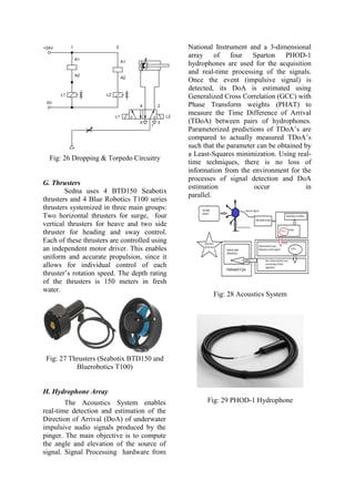
The vehicle uses a pneumatic
cylinder assembly for dropping markers.
The piston is actuated using a double
acting cylinder, which is connected to a
solenoid valve allowing the marker to fall
into the bin. This design was chosen due to
its low offset and high accuracy.
Fig: 26 Dropping & Torpedo Circuitry
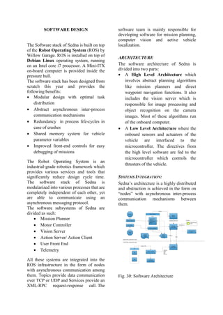
G. Thrusters
Sedna uses 4 BTD150 Seabotix
thrusters and 4 Blue Robotics T100 series
thrusters systemized in three main groups:
Two horizontal thrusters for surge, four
vertical thrusters for heave and two side
thruster for heading and sway control.
Each of these thrusters are controlled using
an independent motor driver. This enables
uniform and accurate propulsion, since it
allows for individual control of each
thruster’s rotation speed. The depth rating
of the thrusters is 150 meters in fresh
water.
Fig: 27 Thrusters (Seabotix BTD150 and
Bluerobotics T100)
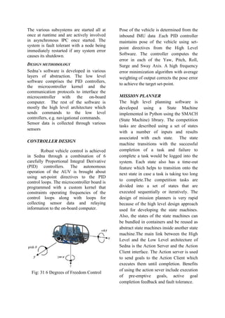
H. Hydrophone Array
The Acoustics System enables
real-time detection and estimation of the
Direction of Arrival (DoA) of underwater
impulsive audio signals produced by the
pinger. The main objective is to compute
the angle and elevation of the source of
signal. Signal Processing hardware from
National Instrument and a 3-dimensional
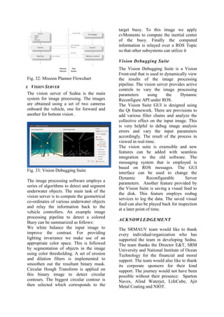
array of four Sparton PHOD-1
hydrophones are used for the acquisition
and real-time processing of the signals.
Once the event (impulsive signal) is
detected, its DoA is estimated using
Generalized Cross Correlation (GCC) with
Phase Transform weights (PHAT) to
measure the Time Difference of Arrival
(TDoA) between pairs of hydrophones.
Parameterized predictions of TDoA’s are
compared to actually measured TDoA’s
such that the parameter can be obtained by
a Least-Squares minimization. Using real-
time techniques, there is no loss of
information from the environment for the
processes of signal detection and DoA
estimation occur in
parallel.
Fig: 28 Acoustics System
Fig: 29 PHOD-1 Hydrophone
SOFTWARE DESIGN
The Software stack of Sedna is built on top
of the Robot Operating System (ROS) by
Willow Garage. ROS is installed on top of
Debian Linux operating system, running
on an Intel core i7 processor. A Mini-ITX
on-board computer is provided inside the
pressure hull.
The software stack has been designed from
scratch this year and provides the
following benefits:
 Modular design with optimal task
distribution
 Abstract asynchronous inter-process
communication mechanisms
 Redundancy in process life-cycles in
case of crashes
 Shared memory system for vehicle
parameter variables
 Improved front-end controls for easy
debugging of missions
The Robot Operating System is an
industrial-grade robotics framework which
provides various services and tools that
significantly reduce design cycle time.
The software stack of Sedna is
modularized into various processes that are
completely independent of each other, yet
are able to communicate using an
asynchronous messaging protocol.
The software subsystems of Sedna are
divided as such:
 Mission Planner
 Motor Controller
 Vision Server
 Action Server/ Action Client
 User Front End
 Telemetry
All these systems are integrated into the
ROS infrastructure in the form of nodes
with asynchronous communication among
them. Topics provide data communication
over TCP or UDP and Services provide an
XML-RPC request-response call. The
software team is mainly responsible for
developing software for mission planning,
computer vision and active vehicle
localization.
ARCHITECTURE
The software architecture of Sedna is
divided into two parts:
 A High Level Architecture which
involves abstract planning algorithms
like mission planners and direct
waypoint navigation functions. It also
includes the vision server which is
responsible for image processing and
object recognition on the camera
images. Most of these algorithms run
of the onboard computer.
 A Low Level Architecture where the
onboard sensors and actuators of the
vehicle are interfaced to the
microcontroller. The directives from
the high level software are fed to the
microcontroller which controls the
thrusters of the vehicle.
SYSTEMS INTEGRATION:
Sedna’s architecture is a highly distributed
and abstraction is achieved in the form on
“nodes” with asynchronous inter-process
communication mechanisms between
them.
Fig. 30: Software Architecture
The various subsystems are started all at
once at runtime and are actively involved
in asynchronous IPC once started. The
system is fault tolerant with a node being
immediately restarted if any system error
causes its shutdown.
DESIGN METHODOLOGY
Sedna’s software is developed in various
layers of abstraction. The low level
software comprises the PID controllers,
the microcontroller kernel and the
communication protocols to interface the
microcontroller with the on-board
computer. The rest of the software is
mostly the high level architecture which
sends commands to the low level
controllers, e.g. navigational commands.
Sensor data is collected through various
sensors
CONTROLLER DESIGN
Robust vehicle control is achieved
in Sedna through a combination of 6
carefully Proportional Integral Derivative
(PID) controllers. The autonomous
operation of the AUV is brought about
using set-point directives to the PID
control loops. The microcontroller board is
programmed with a custom kernel that
constraints operating frequencies of the
control loops along with loops for
collecting sensor data and relaying
information to the on-board computer.
Fig: 31 6 Degrees of Freedom Control
Pose of the vehicle is determined from the
inbound IMU data .Each PID controller
maintains pose of the vehicle using set-
point directives from the High Level
Software. The controller computes the
error in each of the Yaw, Pitch, Roll,
Surge and Sway Axis. A high frequency
error minimization algorithm with average
weighting of output corrects the pose error
to achieve the target set-point.
MISSION PLANNER
The high level planning software is
developed using a State Machine
implemented in Python using the SMACH
(State Machine) library. The competition
tasks are described using a set of states
with a number of inputs and results
associated with each state. The state
machine transitions with the successful
completion of a task and failure to
complete a task would be logged into the
system. Each state also has a time-out
feature which helps to transition onto the
next state in case a task is taking too long
to complete.The competition tasks are
divided into a set of states that are
executed sequentially or iteratively. The
design of mission planners is very rapid
because of the high level design approach
used for developing the state machines.
Also, the states of the state machines can
be bundled in containers and be reused as
abstract state machines inside another state
machine.The main link between the High
Level and the Low Level architecture of
Sedna is the Action Server and the Action
Client interface. The Action server is used
to send goals to the Action Client which
executes them until completion. Benefits
of using the action sever include execution
of pre-emptive goals, active goal
completion feedback and fault tolerance.
Fig. 32: Mission Planner Flowchart
I. VISION SERVER
The vision server of Sedna is the main
system for image processing. The images
are obtained using a set of two cameras
onboard the vehicle, one for forward and
another for bottom vision .
Fig. 33: Vision Debugging Suite
The image processing software employs a
series of algorithms to detect and segment
underwater objects. The main task of the
vision server is to compute the geometrical
co-ordinates of various underwater objects
and relay the information back to the
vehicle controllers. An example image
processing pipeline to detect a colored
Buoy can be summarized as follows:
We white balance the input image to
improve the contrast. For providing
lighting invariance we make use of an
appropriate color space. This is followed
by segmentation of objects in the image
using color thresholding. A set of erosion
and dilation filters is implemented to
smoothen out the resultant binary mask.
Circular Hough Transform is applied on
this binary image to detect circular
contours. The biggest circular contour is
then selected which corresponds to the
target buoy. To this image we apply
cvMoments to compute the inertial center
of the buoy. Finally the computed
information is relayed over a ROS Topic
so that other subsystems can utilize it
Vision Debugging Suite
The Vision Debugging Suite is a Vision
Front-end that is used to dynamically view
the results of the image processing
pipeline. The vision server provides active
controls to vary the image processing
parameters using the Dynamic
Reconfigure API under ROS.
The Vision Suite GUI is designed using
the Qt framework. There are provisions to
add various filter chains and analyze the
collective effect on the input image. This
is very helpful to debug image analysis
errors and vary the input parameters
accordingly. The result of the process in
viewed in real-time.
The vision suite is extensible and new
features can be added with seamless
integration to the old software. The
messaging system that is employed is
based on ROS messages. The GUI
interface can be used to change the
Dynamic Reconfigurable Server
parameters. Another feature provided by
the Vision Suite is saving a visual feed to
the disk. This feature employs rosbag
services to log the data. The saved visual
feed can also be played back for inspection
at a later point of time.
ACKNOWLEDGEMENT
The SRMAUV team would like to thank
every individual/organization who has
supported the team in developing Sedna.
The team thanks the Director E&T, SRM
University and National Institute of Ocean
Technology for the financial and moral
support. The team would also like to thank
its corporate sponsors for their kind
support. The journey would not have been
possible without their presence: Sparton
Navex, Alind Waterjet, LifeCube, Ajit
Metal Coating and NIOT.

More Related Content

What's hot

Modelling and control of a quad rotor robot
Modelling and control of a quad rotor robotModelling and control of a quad rotor robot
Modelling and control of a quad rotor robotPrasanna Ramamurthy
 
Fabrication of drone
Fabrication of droneFabrication of drone
Fabrication of droneRajnish Kumar
 
CLW VOCATIONAL TRAINING REPORT- 2018
CLW VOCATIONAL TRAINING REPORT- 2018CLW VOCATIONAL TRAINING REPORT- 2018
CLW VOCATIONAL TRAINING REPORT- 2018SohagSarkar2
 
Omni Directional Robot
Omni Directional RobotOmni Directional Robot
Omni Directional Robotprashanth15
 
Control Systems Design: The Dumbwaiter 2.0
Control Systems Design: The Dumbwaiter 2.0Control Systems Design: The Dumbwaiter 2.0
Control Systems Design: The Dumbwaiter 2.0Roderik S
 
Fabrication of drone (Synopsis only)
Fabrication of drone (Synopsis only)Fabrication of drone (Synopsis only)
Fabrication of drone (Synopsis only)Rajnish Kumar
 
POH,BTC BHUSAWAL AND INTRO TO SIGNALLING
POH,BTC BHUSAWAL  AND INTRO TO SIGNALLINGPOH,BTC BHUSAWAL  AND INTRO TO SIGNALLING
POH,BTC BHUSAWAL AND INTRO TO SIGNALLINGParmeet singh
 
Human Sensitivity In Forced Feedback Systems (07 31 2009 02 28 18)
Human Sensitivity In Forced Feedback Systems (07 31 2009 02 28 18)Human Sensitivity In Forced Feedback Systems (07 31 2009 02 28 18)
Human Sensitivity In Forced Feedback Systems (07 31 2009 02 28 18)pnimmag1
 
ROBOCON 2015 Documentation
ROBOCON 2015 DocumentationROBOCON 2015 Documentation
ROBOCON 2015 DocumentationVamsi Krishna
 
Brijeh yadav ppt
Brijeh yadav pptBrijeh yadav ppt
Brijeh yadav pptbky2756
 
POWER SUPPLY SYSTEM IN TRAIN COACHES
POWER SUPPLY SYSTEM IN TRAIN COACHESPOWER SUPPLY SYSTEM IN TRAIN COACHES
POWER SUPPLY SYSTEM IN TRAIN COACHESmhjit
 
Diesel locomotive technology
Diesel locomotive technologyDiesel locomotive technology
Diesel locomotive technologyRajneesh Budania
 
IMPROVING POWER FACTORS BY USING LANDSMAN CONVERTER IN PMBLDC MOTOR
IMPROVING POWER FACTORS BY USING LANDSMAN CONVERTER IN PMBLDC MOTORIMPROVING POWER FACTORS BY USING LANDSMAN CONVERTER IN PMBLDC MOTOR
IMPROVING POWER FACTORS BY USING LANDSMAN CONVERTER IN PMBLDC MOTORvivatechijri
 

What's hot (18)

Modelling and control of a quad rotor robot
Modelling and control of a quad rotor robotModelling and control of a quad rotor robot
Modelling and control of a quad rotor robot
 
Fabrication of drone
Fabrication of droneFabrication of drone
Fabrication of drone
 
CLW VOCATIONAL TRAINING REPORT- 2018
CLW VOCATIONAL TRAINING REPORT- 2018CLW VOCATIONAL TRAINING REPORT- 2018
CLW VOCATIONAL TRAINING REPORT- 2018
 
Omni Directional Robot
Omni Directional RobotOmni Directional Robot
Omni Directional Robot
 
Control Systems Design: The Dumbwaiter 2.0
Control Systems Design: The Dumbwaiter 2.0Control Systems Design: The Dumbwaiter 2.0
Control Systems Design: The Dumbwaiter 2.0
 
Fabrication of drone (Synopsis only)
Fabrication of drone (Synopsis only)Fabrication of drone (Synopsis only)
Fabrication of drone (Synopsis only)
 
POH,BTC BHUSAWAL AND INTRO TO SIGNALLING
POH,BTC BHUSAWAL  AND INTRO TO SIGNALLINGPOH,BTC BHUSAWAL  AND INTRO TO SIGNALLING
POH,BTC BHUSAWAL AND INTRO TO SIGNALLING
 
Drone project report
Drone project reportDrone project report
Drone project report
 
Indian railways
Indian railwaysIndian railways
Indian railways
 
Human Sensitivity In Forced Feedback Systems (07 31 2009 02 28 18)
Human Sensitivity In Forced Feedback Systems (07 31 2009 02 28 18)Human Sensitivity In Forced Feedback Systems (07 31 2009 02 28 18)
Human Sensitivity In Forced Feedback Systems (07 31 2009 02 28 18)
 
Main report
Main reportMain report
Main report
 
ROBOCON 2015 Documentation
ROBOCON 2015 DocumentationROBOCON 2015 Documentation
ROBOCON 2015 Documentation
 
Sokkia
SokkiaSokkia
Sokkia
 
Sandeep
SandeepSandeep
Sandeep
 
Brijeh yadav ppt
Brijeh yadav pptBrijeh yadav ppt
Brijeh yadav ppt
 
POWER SUPPLY SYSTEM IN TRAIN COACHES
POWER SUPPLY SYSTEM IN TRAIN COACHESPOWER SUPPLY SYSTEM IN TRAIN COACHES
POWER SUPPLY SYSTEM IN TRAIN COACHES
 
Diesel locomotive technology
Diesel locomotive technologyDiesel locomotive technology
Diesel locomotive technology
 
IMPROVING POWER FACTORS BY USING LANDSMAN CONVERTER IN PMBLDC MOTOR
IMPROVING POWER FACTORS BY USING LANDSMAN CONVERTER IN PMBLDC MOTORIMPROVING POWER FACTORS BY USING LANDSMAN CONVERTER IN PMBLDC MOTOR
IMPROVING POWER FACTORS BY USING LANDSMAN CONVERTER IN PMBLDC MOTOR
 

Similar to SRM_Journal_RS2015

IRJET- Design and Fabrication of Hexacopter for Surveillance
IRJET-  	  Design and Fabrication of Hexacopter for SurveillanceIRJET-  	  Design and Fabrication of Hexacopter for Surveillance
IRJET- Design and Fabrication of Hexacopter for SurveillanceIRJET Journal
 
OEC - 9800 C-Arm service manual.pdf
OEC - 9800 C-Arm service manual.pdfOEC - 9800 C-Arm service manual.pdf
OEC - 9800 C-Arm service manual.pdfarnaldoenriqueborges
 
Team Hyperlynx SpaceX Hyperloop Pod Final Design
Team Hyperlynx SpaceX Hyperloop Pod Final DesignTeam Hyperlynx SpaceX Hyperloop Pod Final Design
Team Hyperlynx SpaceX Hyperloop Pod Final DesignJack Nelson
 
DESIGN AND FABRICATION OF TWINROTOR UAV
DESIGN AND FABRICATION OF TWINROTOR UAVDESIGN AND FABRICATION OF TWINROTOR UAV
DESIGN AND FABRICATION OF TWINROTOR UAVcscpconf
 
bi copter Major project report ER.Abhishek upadhyay b.tech (ECE)
bi copter  Major project report ER.Abhishek upadhyay b.tech (ECE)bi copter  Major project report ER.Abhishek upadhyay b.tech (ECE)
bi copter Major project report ER.Abhishek upadhyay b.tech (ECE)abhishek upadhyay
 
Design optimization of excavator bucket using Finite Element Method
Design optimization of excavator bucket using Finite Element MethodDesign optimization of excavator bucket using Finite Element Method
Design optimization of excavator bucket using Finite Element MethodIjripublishers Ijri
 
LOCOMOTIVE WHEEL ASSEMBLY DESIGN OPTIMIZATION USING FINITE ELEMENT ANALYSIS
LOCOMOTIVE WHEEL ASSEMBLY DESIGN OPTIMIZATION USING FINITE ELEMENT ANALYSISLOCOMOTIVE WHEEL ASSEMBLY DESIGN OPTIMIZATION USING FINITE ELEMENT ANALYSIS
LOCOMOTIVE WHEEL ASSEMBLY DESIGN OPTIMIZATION USING FINITE ELEMENT ANALYSISIjripublishers Ijri
 
Design of an autonomous ornithopter with live video
Design of an autonomous ornithopter with live videoDesign of an autonomous ornithopter with live video
Design of an autonomous ornithopter with live videoeSAT Publishing House
 
Design of an autonomous ornithopter with live video reception for military su...
Design of an autonomous ornithopter with live video reception for military su...Design of an autonomous ornithopter with live video reception for military su...
Design of an autonomous ornithopter with live video reception for military su...eSAT Journals
 
Feasibility Study and Design of Electromagnetic Suspension Systems: A Review
Feasibility Study and Design of Electromagnetic Suspension Systems: A ReviewFeasibility Study and Design of Electromagnetic Suspension Systems: A Review
Feasibility Study and Design of Electromagnetic Suspension Systems: A ReviewIRJET Journal
 
IRJET- Multilevel Object Sorting System using PLC Controller
IRJET-  	  Multilevel Object Sorting System using PLC ControllerIRJET-  	  Multilevel Object Sorting System using PLC Controller
IRJET- Multilevel Object Sorting System using PLC ControllerIRJET Journal
 
DESIGN AND ANALYSIS OF FRAME FOR MOBILE SOLAR POWER STATION
DESIGN AND ANALYSIS OF FRAME FOR MOBILE SOLAR POWER STATIONDESIGN AND ANALYSIS OF FRAME FOR MOBILE SOLAR POWER STATION
DESIGN AND ANALYSIS OF FRAME FOR MOBILE SOLAR POWER STATIONIRJET Journal
 
Low cost Real Time Centralized Speed Control of DC Motor Using Lab View -NI U...
Low cost Real Time Centralized Speed Control of DC Motor Using Lab View -NI U...Low cost Real Time Centralized Speed Control of DC Motor Using Lab View -NI U...
Low cost Real Time Centralized Speed Control of DC Motor Using Lab View -NI U...IJPEDS-IAES
 
Design Portfolio - John Chiu
Design Portfolio - John ChiuDesign Portfolio - John Chiu
Design Portfolio - John ChiuJohn Chiu
 
Engineering Paper - Orion Crew Module Water Landing Simulation at NASA
Engineering Paper - Orion Crew Module Water Landing Simulation at NASAEngineering Paper - Orion Crew Module Water Landing Simulation at NASA
Engineering Paper - Orion Crew Module Water Landing Simulation at NASAAltair ProductDesign
 

Similar to SRM_Journal_RS2015 (20)

AUV CDR
AUV CDRAUV CDR
AUV CDR
 
AEM Poster
AEM PosterAEM Poster
AEM Poster
 
IRJET- Design and Fabrication of Hexacopter for Surveillance
IRJET-  	  Design and Fabrication of Hexacopter for SurveillanceIRJET-  	  Design and Fabrication of Hexacopter for Surveillance
IRJET- Design and Fabrication of Hexacopter for Surveillance
 
OEC - 9800 C-Arm service manual.pdf
OEC - 9800 C-Arm service manual.pdfOEC - 9800 C-Arm service manual.pdf
OEC - 9800 C-Arm service manual.pdf
 
Team Hyperlynx SpaceX Hyperloop Pod Final Design
Team Hyperlynx SpaceX Hyperloop Pod Final DesignTeam Hyperlynx SpaceX Hyperloop Pod Final Design
Team Hyperlynx SpaceX Hyperloop Pod Final Design
 
DESIGN AND FABRICATION OF TWINROTOR UAV
DESIGN AND FABRICATION OF TWINROTOR UAVDESIGN AND FABRICATION OF TWINROTOR UAV
DESIGN AND FABRICATION OF TWINROTOR UAV
 
bi copter Major project report ER.Abhishek upadhyay b.tech (ECE)
bi copter  Major project report ER.Abhishek upadhyay b.tech (ECE)bi copter  Major project report ER.Abhishek upadhyay b.tech (ECE)
bi copter Major project report ER.Abhishek upadhyay b.tech (ECE)
 
Design optimization of excavator bucket using Finite Element Method
Design optimization of excavator bucket using Finite Element MethodDesign optimization of excavator bucket using Finite Element Method
Design optimization of excavator bucket using Finite Element Method
 
LOCOMOTIVE WHEEL ASSEMBLY DESIGN OPTIMIZATION USING FINITE ELEMENT ANALYSIS
LOCOMOTIVE WHEEL ASSEMBLY DESIGN OPTIMIZATION USING FINITE ELEMENT ANALYSISLOCOMOTIVE WHEEL ASSEMBLY DESIGN OPTIMIZATION USING FINITE ELEMENT ANALYSIS
LOCOMOTIVE WHEEL ASSEMBLY DESIGN OPTIMIZATION USING FINITE ELEMENT ANALYSIS
 
Design of an autonomous ornithopter with live video
Design of an autonomous ornithopter with live videoDesign of an autonomous ornithopter with live video
Design of an autonomous ornithopter with live video
 
Design of an autonomous ornithopter with live video reception for military su...
Design of an autonomous ornithopter with live video reception for military su...Design of an autonomous ornithopter with live video reception for military su...
Design of an autonomous ornithopter with live video reception for military su...
 
Feasibility Study and Design of Electromagnetic Suspension Systems: A Review
Feasibility Study and Design of Electromagnetic Suspension Systems: A ReviewFeasibility Study and Design of Electromagnetic Suspension Systems: A Review
Feasibility Study and Design of Electromagnetic Suspension Systems: A Review
 
IRJET- Multilevel Object Sorting System using PLC Controller
IRJET-  	  Multilevel Object Sorting System using PLC ControllerIRJET-  	  Multilevel Object Sorting System using PLC Controller
IRJET- Multilevel Object Sorting System using PLC Controller
 
DESIGN AND ANALYSIS OF FRAME FOR MOBILE SOLAR POWER STATION
DESIGN AND ANALYSIS OF FRAME FOR MOBILE SOLAR POWER STATIONDESIGN AND ANALYSIS OF FRAME FOR MOBILE SOLAR POWER STATION
DESIGN AND ANALYSIS OF FRAME FOR MOBILE SOLAR POWER STATION
 
I012426273
I012426273I012426273
I012426273
 
Final Year Project
Final Year ProjectFinal Year Project
Final Year Project
 
Low cost Real Time Centralized Speed Control of DC Motor Using Lab View -NI U...
Low cost Real Time Centralized Speed Control of DC Motor Using Lab View -NI U...Low cost Real Time Centralized Speed Control of DC Motor Using Lab View -NI U...
Low cost Real Time Centralized Speed Control of DC Motor Using Lab View -NI U...
 
Design Portfolio - John Chiu
Design Portfolio - John ChiuDesign Portfolio - John Chiu
Design Portfolio - John Chiu
 
Engineering Paper - Orion Crew Module Water Landing Simulation at NASA
Engineering Paper - Orion Crew Module Water Landing Simulation at NASAEngineering Paper - Orion Crew Module Water Landing Simulation at NASA
Engineering Paper - Orion Crew Module Water Landing Simulation at NASA
 
TSSRP Poster
TSSRP PosterTSSRP Poster
TSSRP Poster
 

SRM_Journal_RS2015

  • 1. SRM University Autonomous Underwater Vehicle Concept and Design of AUV Sedna Website: www.srmauv.com Akshaya Raj Dayal , Aniket Ray, Abhishek Bansal, Aakash Khurana, Malle Veera Goutham Abstract-SRM University Autonomous Underwater Vehicle Team is an undergraduate team of students that develop AUVs for competition and research. The AUV Sedna is developed in a design cycle of six months. CAD modeling and CNC techniques were used for in-house fabrication. The vehicle is equipped with an array of sensors including two vision cameras ,an Inertial Measurement Unit, passive SONAR array and a pair of pressure sensors. These sensors enable the vehicle to navigate seamlessly and enable it to hear, see and measure its speed, acceleration and underwater positioning. In order to interact with the environment, the AUV is equipped with 8 thrusters, an active grabber and a torpedo launcher. he development of Autonomous Underwater Vehicles has gained a momentum with the advancement of the field of robotics. The need for rapidly deployable underwater vehicles that can be used in challenging environments is on the rise. Well designed AUV’s can provide a reconfigurable platform for various industries such as ocean research, oil and natural gas and many more. SRMAUV is a group of passionate undergraduate students studying at SRM University, Chennai. The goal of the team is to develop a functioning efficient, robust Autonomous Underwater Vehicle that may be used for research and development along with participating in the annual Autonomous Unmanned Vehicle System International (AUVSI) and the Office of Naval Research (ONR) Robosub Competition at San Diego . The aim of the AUV is to complete an obstacle course of real life tasks presented at the competition. The tasks may involve following path segments ,navigating through gates ,maintaining heading, touching buoys, launching torpedoes, dropping markers, locating acoustic beacons and manipulating objects. To achieve all this the vehicle needs to have swift movement and accurate positioning. The vehicle needs to be aware of its position at all times. Hence vehicle localization plays a prime role. Specific subsystems have been developed to handle underwater tasks. Fig: 1.1 AUV Sedna T
  • 2. MECHANICAL DESIGN A. OVERVIEW The mechanical design for Sedna was planned with the goal of making the AUV modular, compact and lightweight. The hull contains a sliding deck with a rack system, facilitating removal and centralized access to the electronic components. The external frame is designed to foster future modification of the AUV with minimal effort. The software tools used in modeling and analysis are SolidWorks, Catia and ANSYS. Fig: 1.2 Solidworks rendering of AUV Sedna VEHICLE SPECIFICATIONS: • Depth rating : o 50ft (Acrylic Hull) • Max speed: 0.6 m/s • Overall Dimensions: 48" L x 24" W x 21" H, • Weight:45kg • Run time: 1 hours 30 minutes • 8 x Thrusters for active Yaw, Pitch, Heave, Surge and Roll Control B. HULL Acrylic is the material chosen for construction of the hull. Acrylic refers to a family of synthetic or man-made plastic materials, containing one or more derivatives of acrylic acid. The hull has an inner diameter of 290 mm and an outer diameter of 300 mm. It is designed to be watertight in order to insulate the internal electrical systems from water damage. The hull end-cap features waterproof connectors, allowing external components to access the electrical systems inside the hull. The front and back end-caps are machined from Aluminum blocks to facilitate passive heat conduction. The cylinder is made from acrylic to provide a clear view of the hull components for inspection. Fig: 1 Acrylic Hull Fig: 2 Hull Deformation analysis
  • 3. C. EXTERNAL FRAME For the frame to be modular, a drill pattern is applied over its surface. The frame is made of aluminum and hard- anodized for structural stability. It was designed in such a way that the total deformation, von mission stress and strains are always minimum. All the components are directly secured to the frame. The frame design provides an unobstructed flow for the thrusters. Structural analysis using ANSYS is done to ensure structural rigidity. The frame consists of 2 side plates made up of Al-6061-T6 having a thickness of 6mm.The dimension of each plate is 1100mm x 500mm the width of the frame is 500mm. The frame accommodates 8 thrusters for Surge, Heave, Yaw and Pitch Control. Handles attached to the frame are provided for easy transportation of the AUV. Fig: 3 Frame Fig: 4 Frame Deformation analysis Fig: 5 Frame Stress analysis Fig: 7 Frame Strain analysis D. PNEUMATIC SYSTEMS The pneumatics systems are used to drive the following manipulators attached to the frame : • Grabber Mechanism • Dropper Mechanism • Torpedo Mechanism (i)Active grabber mechanism: The grabbing mechanism is powered by a pneumatic piston which allows controlled grabbing and release using compressed air. The pneumatic grabber is utilized to grab underwater mission objects.To grab, the piston extends and the grabber arms close around the PVC object, securing it for transport to the second recovery area.
  • 4. To release, a second set of valves is opened to force air into the other half of the piston, opening the grabber. A CO2 cartridge is provided to contain compressed air .Here we use a Rexroth PRA-D32 pneumatic cylinder which can effectively functional even at higher pressures. Fig: 8 Active Grabber Fig: 9 Electrical Circuit for grabber (ii)Dropper mechanism: Two droppers are mounted below the hull. A magnetic coil is used to actuate the dropper using an electric pulse. This provides for dropping markers in competition bins. The dropper is made heavy so it can fall directly in line with the marker bins. Custom electromagnet actuation is used for this purpose. The dropper actuation mechanism weighs at 0.5 kg. Fig: 10 Dropper Fig: 11 : Electrical Circuit for Dropper (iii) Torpedo Two independent pneumatic torpedo- shooting mechanisms are provided which have been 3D printed with a drag- optimized profile. The torpedo is activated using a pressure release valve that is solenoid controlled. Neutrally buoyant torpedoes provides stable water dynamics and easy recoverability. E. Custom enclosures: Custom sensor/electronics/battery enclosures are designed using CAD software and optimal precision CNC fabrication techniques are chosen for fabrication using aluminum Battery Pod A battery pod houses the Li-Po batteries onboard Sedna. Pressure release valves and connector slots are provided on the periphery. The pod is water tightened using an axial sealing mechanism and can easily be swapped
  • 5. to provide continuous vehicle operation. Fig: 6 Battery Pod Fig: 13 Battery pod Deformation analysis Camera Enclosure: Two custom camera enclosures have been fabricated for the front and bottom vision cameras. Clear acrylic front panels provide an unrestricted field of view. ELECTRICAL DESIGN A. Overview The electrical infrastructure consists of Power Management Systems, Acoustic Signal Processing and Sensor payload Electronics, so as to cater the needs of constantly evolving software and mechanical components. The design ensures modularity in the electrical system for allowing boards to be reused through multiple design iterations and provides support for future unforeseen requirements. The Mini-ITX motherboard, microcontroller carrier board, Batteries and Power Supply Units are the main electrical components which are enclosed within the hull. In addition, a number of sensors and protection circuits have also been incorporated to make the system robust. Fig: 14 Sedna's Backplane B. Power Management System A dedicated Power Management System is developed to support the on- board electronics and sensor payload. A Battery Management System is developed for optimal power distribution among various boards such as the onboard CPU, thrusters and the microcontroller board. A Battery Management and Protection board is custom designed to provide even discharge of Lithium Polymer (Li-Po) batteries. A visual feedback system to provide battery level information for thrusters and electronic peripherals is developed. Special care has been taken to ensure water leakage detection and overheating. Each component is protected with resettable fuses. Sedna is powered by five 11.1V (3S), 8Ah Lithium Polymer batteries in parallel. a. Power Monitoring: A custom board has been designed to monitor the power level of each battery which is also provided with a Hall Effect current sensor to continuously measure the
  • 6. current. A point contact temperature sensor is placed on each battery to continuously measure the temperature. A graphic LCD displays the status of the batteries, power lines and hull temperature. LED strip lighting provides visual feedback for software debugging. b. Power Distribution: A M4-ATX (250W) power supply unit provides power to the mainboard computer which is equipped with features like programmable voltage output and time out auto shutdown features. A DC-DC boost converter receives the raw voltage from batteries and converts it to different levels of voltage (5v, 12v, 18v) required by microcontrollers, actuators and sensor payloads. These channels are monitored and displayed on the LCD and protected in case of an overcurrent or overvoltage. Components Avg. Power Require d (w) Quan tity Total (w) Thrusters 60 8 480 Computing Unit 55 1 55 Display Unit 10 1 10 Total Power Required 545 Fig. 15 : Power distribution Fig: 16 Battery Management Board C. Onboard Computer Computer design for Sedna is governed by the vehicle’s need to perform complex computer vision and machine learning in real time in spite of restrictive space requirements. The software system is powered by an Intel Haswell CPU Core i7-4785T quad core processor with a maximum Thermal Dissipation Power (TDP) of 35W on a Gigabyte GA-Z97N- WIFi motherboard along with a 256 GB SATA Solid State Drive (SSD). The Motherboard requires a non-fluctuating and uninterrupted DC power supply to deliver optimum performance, and it is provided by M4-ATX (250W) PSU. A USB hub interfaces the embedded sensors and actuators as well as other serial devices, i.e. Battery Management System (BMS), AHRS-8 and cameras. The main purpose of the Arduino board is interfacing Sedna’s various sensors and thruster. Fig: 17 Gigabyte GA-Z97N-WIFi Mini-ITX Motherboard Fig: 18 Arduino Mega 2560
  • 7. D. Sensors Sedna is equipped with a suite of sensors used for sensing the environment and providing orientation feedback as well as odometry information.Sensors for current, temperature, inertia, angular velocity, pressure and leakage are used in Sedna. Two vision cameras are provided for driving the image processing software stack. The sensor suite provides 6 degree of freedom state space solution. A brief description of the sensors is given below: a. Pressure Sensor The vehicle uses UltraStable™ US300 Series and SWITZER 717-V series submersible pressure transducer to obtain analog pressure data. The sensor returns the pressure exerted by the mass of water above the vehicle. Using Pascal's Law, the depth of the vehicle is extrapolated. Fig: 19 UltraStable™ US300 Series Pressure sensor b. Inertial Measurement Unit (IMU) Sedna is equipped with a MEMS based Sparton AHRS-8 system It is fully temperature compensated and uses Advance sensing technology (3-axis magnetic, 3-axis MEMS acceleration, and 3-axis MEMS gyro) to compute yaw, pitch and roll measurements. It provides critical inertial data at a rapid rate of 100 Hz. The IMU is used to provide vehicle angular velocities and linear acceleration that is used to compute the pose of the vehicle. Fig: 20 Sparton AHRS-8 c. Camera Sedna uses two Microsoft LifeCam cinema cameras, one forward and other at bottom. Cameras are used to drive the vision system of the vehicle and are housed in custom fabricated external enclosures that provide a clear field of view to the camera lenses. Fig: 21 Microsoft LifeCam cinema d. Current Sensor A low noise producing current sensor is used in Sedna. Hall Effect current sensors (ACS 709) are used by the power board to get a feedback of current being consumed from the batteries, It continuously monitors the current going in and out of the battery. Fig: 22 ACS709 Hall Effect Current Sensor
  • 8. e. Temperature Sensor Sedna utilizes a LM35 digital thermometer temperature sensor. The digital thermometer has the capability of deriving power directly from the data line, thus eliminating the need for an external power supply. The sensor monitors the temperature within the hull in areas where higher temperatures might be a cause of concern. Fig: 23 LM35 Temperature Sensor f. Leak Sensor Sedna has integrated leak sensors to detect possible water leaks. It consists of an array of wires. When these wires become wet, an electrical short occurs which is transmitted by a binary signal to the microcontroller and it is processed and desired action is taken. In addition, LED strips are integrated as state indicators. These indicators are especially useful during autonomous runs for understanding the vehicle’s current state. Fig: 24 Leak Sensor E. Batteries Lithium polymer batteries built with Li-Po Nano-technology substrate complex are used for providing power to Sedna. The advantage of using these batteries is that there is less voltage sag and a higher discharge rate. The batteries are connected to a Battery Management System, which efficiently supplies power to the thrusters, microcontroller carrier board, CPU and other components used in the AUV. It can power the AUV for 120 minutes continuously. Fig: 25 Zippy Flightmax 8000mAh F. Kill Switch Sedna is provided with a kill switch which is used to shut down the entire AUV system, in an emergency. When the kill switch is activated, it stops power supply to electronic components completely and disables the thrusters. The kill switch minimizes the risk of the AUV getting damaged when an emergency is detected. Emergency situations include water leakage which may cause short circuiting, attacks caused by marine animals and destructive human activities which may inflict severe damage on the AUV. G. Dropping & Torpedo Circuitry The vehicle uses a pneumatic cylinder assembly for dropping markers. The piston is actuated using a double acting cylinder, which is connected to a solenoid valve allowing the marker to fall into the bin. This design was chosen due to its low offset and high accuracy.
  • 9. Fig: 26 Dropping & Torpedo Circuitry G. Thrusters Sedna uses 4 BTD150 Seabotix thrusters and 4 Blue Robotics T100 series thrusters systemized in three main groups: Two horizontal thrusters for surge, four vertical thrusters for heave and two side thruster for heading and sway control. Each of these thrusters are controlled using an independent motor driver. This enables uniform and accurate propulsion, since it allows for individual control of each thruster’s rotation speed. The depth rating of the thrusters is 150 meters in fresh water. Fig: 27 Thrusters (Seabotix BTD150 and Bluerobotics T100) H. Hydrophone Array The Acoustics System enables real-time detection and estimation of the Direction of Arrival (DoA) of underwater impulsive audio signals produced by the pinger. The main objective is to compute the angle and elevation of the source of signal. Signal Processing hardware from National Instrument and a 3-dimensional array of four Sparton PHOD-1 hydrophones are used for the acquisition and real-time processing of the signals. Once the event (impulsive signal) is detected, its DoA is estimated using Generalized Cross Correlation (GCC) with Phase Transform weights (PHAT) to measure the Time Difference of Arrival (TDoA) between pairs of hydrophones. Parameterized predictions of TDoA’s are compared to actually measured TDoA’s such that the parameter can be obtained by a Least-Squares minimization. Using real- time techniques, there is no loss of information from the environment for the processes of signal detection and DoA estimation occur in parallel. Fig: 28 Acoustics System Fig: 29 PHOD-1 Hydrophone
  • 10. SOFTWARE DESIGN The Software stack of Sedna is built on top of the Robot Operating System (ROS) by Willow Garage. ROS is installed on top of Debian Linux operating system, running on an Intel core i7 processor. A Mini-ITX on-board computer is provided inside the pressure hull. The software stack has been designed from scratch this year and provides the following benefits:  Modular design with optimal task distribution  Abstract asynchronous inter-process communication mechanisms  Redundancy in process life-cycles in case of crashes  Shared memory system for vehicle parameter variables  Improved front-end controls for easy debugging of missions The Robot Operating System is an industrial-grade robotics framework which provides various services and tools that significantly reduce design cycle time. The software stack of Sedna is modularized into various processes that are completely independent of each other, yet are able to communicate using an asynchronous messaging protocol. The software subsystems of Sedna are divided as such:  Mission Planner  Motor Controller  Vision Server  Action Server/ Action Client  User Front End  Telemetry All these systems are integrated into the ROS infrastructure in the form of nodes with asynchronous communication among them. Topics provide data communication over TCP or UDP and Services provide an XML-RPC request-response call. The software team is mainly responsible for developing software for mission planning, computer vision and active vehicle localization. ARCHITECTURE The software architecture of Sedna is divided into two parts:  A High Level Architecture which involves abstract planning algorithms like mission planners and direct waypoint navigation functions. It also includes the vision server which is responsible for image processing and object recognition on the camera images. Most of these algorithms run of the onboard computer.  A Low Level Architecture where the onboard sensors and actuators of the vehicle are interfaced to the microcontroller. The directives from the high level software are fed to the microcontroller which controls the thrusters of the vehicle. SYSTEMS INTEGRATION: Sedna’s architecture is a highly distributed and abstraction is achieved in the form on “nodes” with asynchronous inter-process communication mechanisms between them. Fig. 30: Software Architecture
  • 11. The various subsystems are started all at once at runtime and are actively involved in asynchronous IPC once started. The system is fault tolerant with a node being immediately restarted if any system error causes its shutdown. DESIGN METHODOLOGY Sedna’s software is developed in various layers of abstraction. The low level software comprises the PID controllers, the microcontroller kernel and the communication protocols to interface the microcontroller with the on-board computer. The rest of the software is mostly the high level architecture which sends commands to the low level controllers, e.g. navigational commands. Sensor data is collected through various sensors CONTROLLER DESIGN Robust vehicle control is achieved in Sedna through a combination of 6 carefully Proportional Integral Derivative (PID) controllers. The autonomous operation of the AUV is brought about using set-point directives to the PID control loops. The microcontroller board is programmed with a custom kernel that constraints operating frequencies of the control loops along with loops for collecting sensor data and relaying information to the on-board computer. Fig: 31 6 Degrees of Freedom Control Pose of the vehicle is determined from the inbound IMU data .Each PID controller maintains pose of the vehicle using set- point directives from the High Level Software. The controller computes the error in each of the Yaw, Pitch, Roll, Surge and Sway Axis. A high frequency error minimization algorithm with average weighting of output corrects the pose error to achieve the target set-point. MISSION PLANNER The high level planning software is developed using a State Machine implemented in Python using the SMACH (State Machine) library. The competition tasks are described using a set of states with a number of inputs and results associated with each state. The state machine transitions with the successful completion of a task and failure to complete a task would be logged into the system. Each state also has a time-out feature which helps to transition onto the next state in case a task is taking too long to complete.The competition tasks are divided into a set of states that are executed sequentially or iteratively. The design of mission planners is very rapid because of the high level design approach used for developing the state machines. Also, the states of the state machines can be bundled in containers and be reused as abstract state machines inside another state machine.The main link between the High Level and the Low Level architecture of Sedna is the Action Server and the Action Client interface. The Action server is used to send goals to the Action Client which executes them until completion. Benefits of using the action sever include execution of pre-emptive goals, active goal completion feedback and fault tolerance.
  • 12. Fig. 32: Mission Planner Flowchart I. VISION SERVER The vision server of Sedna is the main system for image processing. The images are obtained using a set of two cameras onboard the vehicle, one for forward and another for bottom vision . Fig. 33: Vision Debugging Suite The image processing software employs a series of algorithms to detect and segment underwater objects. The main task of the vision server is to compute the geometrical co-ordinates of various underwater objects and relay the information back to the vehicle controllers. An example image processing pipeline to detect a colored Buoy can be summarized as follows: We white balance the input image to improve the contrast. For providing lighting invariance we make use of an appropriate color space. This is followed by segmentation of objects in the image using color thresholding. A set of erosion and dilation filters is implemented to smoothen out the resultant binary mask. Circular Hough Transform is applied on this binary image to detect circular contours. The biggest circular contour is then selected which corresponds to the target buoy. To this image we apply cvMoments to compute the inertial center of the buoy. Finally the computed information is relayed over a ROS Topic so that other subsystems can utilize it Vision Debugging Suite The Vision Debugging Suite is a Vision Front-end that is used to dynamically view the results of the image processing pipeline. The vision server provides active controls to vary the image processing parameters using the Dynamic Reconfigure API under ROS. The Vision Suite GUI is designed using the Qt framework. There are provisions to add various filter chains and analyze the collective effect on the input image. This is very helpful to debug image analysis errors and vary the input parameters accordingly. The result of the process in viewed in real-time. The vision suite is extensible and new features can be added with seamless integration to the old software. The messaging system that is employed is based on ROS messages. The GUI interface can be used to change the Dynamic Reconfigurable Server parameters. Another feature provided by the Vision Suite is saving a visual feed to the disk. This feature employs rosbag services to log the data. The saved visual feed can also be played back for inspection at a later point of time. ACKNOWLEDGEMENT The SRMAUV team would like to thank every individual/organization who has supported the team in developing Sedna. The team thanks the Director E&T, SRM University and National Institute of Ocean Technology for the financial and moral support. The team would also like to thank its corporate sponsors for their kind support. The journey would not have been possible without their presence: Sparton Navex, Alind Waterjet, LifeCube, Ajit Metal Coating and NIOT.