(1) The document provides calculations to determine the required base plate thickness for a column base connection according to Eurocode standards. It includes input parameters such as column forces, material properties, bolt sizes and locations.
(2) Three equations are solved simultaneously to determine the maximum pressure under the base plate, tension in the hold down bolts, and active concrete area.
(3) The calculated pressure and bolt tension exceed design values, requiring a redesign of the base plate length/width or use of higher strength concrete.
(4) The minimum required base plate thickness is then calculated based on the design bending moment and material yield strength.
6161103 9.2 center of gravity and center of mass and centroid for a bodyetcenterrbru
This document discusses the center of gravity, center of mass, and centroid of rigid bodies. It defines these terms and presents methods to calculate them using integrals of differential elements. Examples are provided to demonstrate calculating the centroid for areas and lines using appropriate coordinate systems and differential elements. Centroids are found by taking moments of these elements and the document outlines the general procedure to perform these calculations.
The document discusses mechanics of solid deflection in beams. It provides relationships between bending moment and curvature, as well as sign conventions for shear force, bending moment, slope and deflection. It then analyzes simply supported beams with central point loads and uniform distributed loads. Equations are derived for slope, deflection and bending moment at any section. Cantilevers with point loads and uniform distributed loads are also analyzed. Macaulay's method, a versatile technique for determining slope and deflection in beams under various loading conditions, is introduced. Examples applying the concepts to specific beam problems are included.
21-Design of Simple Shear Connections (Steel Structural Design & Prof. Shehab...Hossam Shafiq II
1. The document describes the design of a simple shear connection between a beam and column using bolts. It provides equations to check the shear strength of the bolts and bearing strength of the plate.
2. An example is presented to determine the number and size of bolts needed to resist an ultimate shear force of 1000 kN between two beams. It is determined that 7 bolts with 18 mm diameter and 98.5 mm spacing will suffice.
3. The document also checks the strength of double angles used in the connection to transfer the force and confirms the chosen angles are adequate.
The document contains solutions to problems from Chapter 7 on slab analysis and friction in metal forming processes. Problem 7-1 calculates the power consumed in drawing a steel coil through a pair of dies. Problem 7-2 calculates the friction coefficient from an experimental rod drawing efficiency. Problem 7-3 estimates the force required to coin a quarter.
This document summarizes research on strengthening reinforced concrete beams using fiber reinforced polymer (FRP) sheets. It discusses how FRP strengthening has become a popular technique worldwide due to advantages like high strength, light weight, corrosion resistance, and easy installation. The document reviews literature on strengthening both simply supported and continuous beams. It outlines different FRP strengthening methods and discusses factors that influence the behavior and failure of strengthened beams, such as surface preparation, adhesive type, and concrete strength. The document also discusses design considerations and challenges for FRP strengthening, as well as disadvantages like lack of design codes and fire risk.
This document provides background information and theory on the design of structural steel connections. It is the first edition of Handbook 1: Design of Structural Steel Connections, published in 2007 by the Australian Steel Institute. The handbook was authored by T.J. Hogan and edited by S.A. Munter. It covers topics such as bolted and welded connections, connection components, supported members, and minimum design actions. The intended purpose is to provide guidance on structural steel connection design based on the Australian Standard AS 4100.
This document discusses basic probability concepts including sample spaces, events, counting rules, and probability definitions. It begins by defining a sample space as the set of all possible outcomes of an experiment. Events are defined as subsets of the sample space. Basic counting rules like the multiplication rule, permutations, and combinations are introduced. Probability is defined as a way to quantify the likelihood of events occurring. The document provides examples and explanations of these fundamental probability topics.
This document presents the seismic design project of a 12-story steel frame building in Stockton, California. The objectives are to analyze the building using equivalent lateral force (ELF), modal response spectrum, and modal time history analyses in SAP2000, and to compare the results to FEMA 451 examples. The building is irregular in plan and elevation, posing modeling challenges. The analyses determine member forces and drifts. ELF analysis results in story drifts up to 3.58 inches, within code allowables. Modal and time history analyses will provide more accurate force and deformation estimates for design.
This document provides details of a fixed column base design connection between a column and concrete foundation. It includes the geometry, materials, and loads for the column, baseplate, anchors, concrete, and rebar. The document then provides the results of structural calculations to check the resistances of the connection to compression, tension, bending, pull-out, splitting, and other failure modes according to Eurocode standards. Key values calculated include the bearing resistance, anchor tensile resistance, base plate bending resistance, and column web tensile resistance.
This document outlines key concepts in 2D and 3D force systems. It begins by defining forces and force components in rectangular coordinate systems. It discusses concepts like concentrated vs distributed forces, and contact vs body forces. It also covers moments, couples, and resultants of force systems. Several example problems are provided to demonstrate calculating forces, moments, and resultants for 2D systems.
The document discusses the benefits of exercise for both physical and mental health. Regular exercise can improve cardiovascular health, reduce stress and anxiety, boost mood, and reduce the risk of diseases. It recommends that adults get at least 150 minutes of moderate exercise or 75 minutes of vigorous exercise per week to gain these benefits.
The document discusses STAAD.Pro tips and tricks, including:
1) Creating macros using OpenSTAAD and VBA to automate tasks like displaying maximum displacements from selected nodes.
2) Modeling stage construction by analyzing a structure built in two stages and combining the forces from each stage.
3) Other topics covered are foundations analysis and buckling analysis.
This document summarizes the deformation of rods under axial loading. It discusses the deformation of uniform rods using Hooke's law, as well as rods with multiple loads or non-uniform cross sections. Formulas are provided to calculate the deformation based on the loads, lengths, areas, and moduli of the various sections. An example problem is worked through to demonstrate calculating the deformations of a rod with two connecting links. Non-uniform deformation is also discussed, along with an example of calculating the deflection of a conical rod due to its own weight.
The document provides step-by-step instructions for modeling the failure of a concrete cylinder under compressive loading using Abaqus. It describes how to create the cylinder geometry, apply material properties including damage and failure parameters, apply boundary conditions to rigidly fix one end, apply a pressure load to the other end, create output requests to track displacement and reaction forces, and plot the load-displacement curve. The analysis shows the cylinder fails at a load corresponding to a pressure of 22.64 MPa, which is less than the given pressure of 27 MPa, indicating the material properties need adjustment.
Mechanics of materials 9th edition goodno solutions manualKim92736
This document contains solutions to problems from Chapter 2 of the 9th Edition Mechanics of Materials textbook by Goodno. It lists over 300 problems from sections 2.2 through 2.12 that have been solved, along with the full textbook reference and a link to download the full solutions manual PDF. The problems cover topics in stress, strain, Hooke's law, axial loading, torsion, shear stresses, and more.
Leaf springs are made of beams with uniform strength and are commonly used in automobiles. They consist of multiple leafs stacked together to form a cantilever beam. This distributes the load from the road across the leaves. Stress and deflection analyses show that the stress in the master leaf is 50% higher than in the graduated leaves. However, giving the master leaf a curvature through residual stresses can equalize the stresses across leaves and increase the total load capacity. Equations are derived relating load shared, stresses developed, and maximum deflection to the number and dimensions of leaves.
De tweedaagse cursus M&A in vogelvlucht van DLA Piper werd gehouden op 18 november en 2 december. De juristen van DLA Piper gaven een overzicht van de belangrijkste juridische en fiscale aandachtspunten op het terrein van M&A.
This chapter of the SAFE user's guide provides an overview of the program's graphical user interface. The interface includes a main window, title bars, menu bar, toolbars, up to four display windows, status bar, and mouse pointer position display. It describes the purpose and basic functions of each component to orient the user to the layout and navigation of the program.
This document outlines standards and procedures for determining loads on silo and tank structures from stored bulk materials. It includes definitions of terms and symbols, methods for calculating fill and discharge loads on silo walls, loads in silo hoppers and bottoms, and loads on tanks. Measurement procedures are provided for determining important bulk material parameters needed for load calculations, such as density, wall friction, internal friction, and elasticity. Annexes provide additional guidance, standards, and alternative calculation methods.
UNIT-I-Theories of failures-19072016.pptxPraveen Kumar
The document discusses various theories of material failure under complex loading conditions, including:
1) Maximum principal stress theory (Rankine), which states failure occurs when the maximum principal stress equals the yield stress from a tensile test.
2) Maximum shear stress theory (Guest-Tresca), which states failure occurs when the maximum shear stress equals the shear stress from a tensile test.
3) Maximum principal strain theory (Saint-Venant), which states failure occurs when the maximum principal strain equals the yield strain from a tensile test.
4) Theories also consider total strain energy, maximum shear strain energy, and distortional strain energy.
1. SPINTA METALLOSTATICA
Questi appunti riguardano il calcolo della spinta metallostatica in fonderia. Sono riportati alcuni esercizi tratti dal
CAPELLO – FONDERIA non più ristampato.
1 ) Generalità.
Quando tutta la forma è riempita dalla lega liquida, si genera nella massa
metallica una pressione (metallostatica) p che, per il principio di Pascal, in ogni punto si
esercita ugualmente in tutte le direzioni e che dipende dall'affondamento h del punto
considerato sotto al livello libero del liquido, e dal peso specifico o densità di
quest'ultimo. Il metallo quindi finché è liquido, genera su tutte le pareti della forma, e sulle
anime immerse in esso , una spinta metallostatica .
Una volta solidificato esso grava con il proprio peso sulla parete inferiore della
forma, obbedendo alla sola gravita, e inizia il suo ritiro che dura finché il getto ha
raggiunto la temperatura ambiente.
Negli esempi che seguono si riportano vari casi possibili.
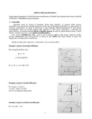
Esempio 1: parete orizzontale affondata
Per un liquido perfetto si ha:
p=γ*h
γ = peso specifico
F = p *S = γ * h* AB * CD
Esempio 2: parete verticale affiorante
F = ∫s p da = γ ∫s h da =
= γ b ∫0H h dh = ½ γ b H2
dove b è la larghezza della parete
Esempio 3: parete verticale non affiorante
F = ½ γ b (h22 – h12)
1
2. Esempio 4: parete inclinata affiorante
F = ∫s p da =
= γ ∫s h da = γ b / sin α ∫0H h dh =
=½ sin α γ b H2
Componente verticale = Fv = ½ tan α γ b H2
Componente orizzontale = Fo = ½ γ b H2
Esempio 5: parete circolare affiorante
Componente verticale
Fv = π /4 γ b r2
Componente orizzontale
Fo = ½ γ b H2
Esempio 6: superficie qualsiasi
La superficie di separazione fra il liquido e la terra di fonderia “sostiene” tutta la colonna di liquido fino
al pelo libero, su tutta la sua estensione
F = γmetallo Vsabbia sopra il getto
Spinte metallostatiche sulle anime
Le anime sono completamente circondate dal metallo
liquido, tranne le loro portate, e quindi sono
assoggettate alla spinta di Archimede:
F = γmetallo (Vanima - Vportate)
Nel calcolo della resistenza allo scoperchiamento della
staffa, a questo valore bisogna sottrarre il peso
dell’anima stessa
Panima = γanima Vanima
2
3. NB: le anime verticali non hanno liquido sulla loro superficie inferiore e quindi non sono soggette a
spinte a meno che non abbiano sotto-squadri.
ESERCIZI
Esercizio 1
Si consideri il caso del getto in Fig. 1: parallelepipedo in ghisa delle dimensioni di
mm 300 • 250 • 200 di altezza, con un incavo, su una delle pareti laterali , del diametro
di 100 mm e della profondità di 180 mm, con colatoio laterale dell'altezza di 230 mm.
Assumendo γ= 7,2 kg/ dm3 il peso specifico della ghisa, si avrà
a) sul fondo,
di area S1 = 3 • 2,5 e immerso h 1 = 3,3 dm,
F1 = 3 * 2,5 * 3,3 * 7,2 = 178,200 kg
diretta verso il basso, e che tende a sfondare la forma, contrastata dalle nervature inferiori e dal
fatto che la staffa è appoggiata al suolo;
b) su ognuna delle due pareti laterali,
di area S 2 = 2,5 * 2 dm 2 e immerse h 2 = 2,3 dm:
F2 = 2,5 * 2 * 2,3 * 7,2 = 82,800 kg
c) su ognuna delle due pareti laterali,
di area S3 = 3 * 2 dm2 e immerse h 3 = h2 = 2,3 dm:
F3 = 3 * 2 * 2,3 * 7,2 = 99,360 kg
Le spinte F2 e F3 applicate nel baricentro delle pareti possono essere contrastate dai fianchi delle
staffe il cui spessore deve essere adeguatamente dimensionato;
d) sulla parete superiore,
di area 3 * 2,5 dm2 e immersa h4 = 1,3 dm:
F4 = 3 * 2,5 * 1,3 * 7,2 = 70,200 kg
che tende a scoperchiare la forma, ed a sfondare la staffa superiore, causando la formazione di bave o lo
spostamento dell'anima 3, o anche la fuoruscita del metallo; il getto risulterà difettoso, di dimensioni
eccessive o incompleto;
e) sull’anima 3
di diametro 1 dm e della sporgenza di 1,8 dm
F5 = Vanima-bagnato * γ = (0,785 *1 2 * 1,8) * 7,2 = 10,175 kg
La portata d’anima ha un peso proprio:
Q 1 = (0,785 *1 2 * 2,0) * 1,6 = 2,260 kg
(peso specifico della sabbia :1,6 kg/ dm3 )
quindi la spinta effettiva che l'anima riceve sarà:
F 6 = F 5 – Q 1 = 10,175 - 2,260 = 7,915 kg
La F 6 tende a deformare o spezzare o spostare verso l'alto l'anima e si somma alla spinta F4,
prima calcolata, che cerca di sollevare la staffa superiore; questa, per evitare gli inconvenienti
accennati, dovrà essere assicurata a quella inferiore con sistemi di serraggio e/o pesi
proporzionati ad una spinta totale:
3
4. F 7 = F 4 + F 6 = 70,200 + 7,915 = 78,115 kg
Il peso della staffa superiore, che agisce in senso favorevole verso il basso, se considerata piena di
sola sabbia , pari a :
Qstaffasup = 3*2,5*1 * 1,6 = 12 kg
è in questo caso trascurabile.
A solidificazione completata , il getto grava con il solo suo peso Q2 :
Q 2 = 108 - 10,175 = 97,825 kg
La spinta F 1 sul fondo è normalmente assorbita , tranne che per i getti molto alti
fusi verticalmente, grazie alle nervature della staffa inferiore e al fatto che questa
appoggia sul pavimento; le spinte laterali F 2 e F 3 danno un indirizzo per la scelta o la
progettazione delle staffe , che saranno più robuste ed in acciaio per le grandi altezze.
Il valore della spinta metallostatica F7 verso l'alto deve essere sempre esattamente
valutata per le grandi forme , al fine di poter garantire un corretto riempimento della forma
ed un getto sano, privo di sbavature.
Per le piccole forme come quella sopraindicata, spesso non si esegue un calcolo vero e
proprio perché è facile equilibrare la spinta verso l'alto sovrapponendo alle staffe dei pesi
stabiliti ad occhio con larghezza e ricorrendo ai sistemi di serraggio.
Negli esempi seguenti si applicheranno i criteri usati in pratica, cioè quelli di
trascurare la spinta sul fondo e le spinte laterali e di tener conto solo di quella verso l'alto.
fig. 1 - Getto da colare (in alto) e formatura (in basso): sono
rappresentate le varie azioni F1, F2, F3, F4 sulle pareti della
forma F5 sull’anima, e la spinta F7 verso l’alto, che cerca di
sollevare la staffa superiore o coperchio: Q è il peso proprio
della parte sporgente dell’anima.
4
5. Esercizio 2
fig. 2 - Formatura di un coperchio ovale con due mozzi
Questo esempio si riferisce ad un coperchio in ghisa di piccole dimensioni formato in
due staffe la cui impronta trovasi tutta nella staffa superiore ( Fig. 2.0).
La superficie S sulla quale si esercita la spinta verso l'alto F è data da
S = S1 + S2 + S3
dove S 1 è la superficie orizzontale delle sporgenze del coperchio, S 2 è la superficie
orizzontale della parte centrale e S3 è la superficie orizzontale della flangia.
Essendo queste tre superfici ad affondamento diverso, la spinta totale F sarà
F = [(S 1 * h 1 ) + (S 2 * h 2 ) + (S 3 * h 3 )] * γ kg
ora
S 1 = 2 (π * 0,6 2 /4) = 0,5654 dm 2
S 2 = (1 * 0,6) - (π * 0,6 2 /4) = 0,6 — 0,2827 = 0,3173 dm 2
S 3 = [(π * (1,2 2 - 0,6 2 ) /4)] + 2 * 1 * 0,3 = 1,4482 dm2
Perciò
F =[(S 1 * h 1) + (S2 * h2) + (S3 * h3)] * γ =
= [(0,5654 * 1,4) + (0,3173 * 1,9) + (1,4482 * 2)] * 7,2 =
= (0,79 + 0,6 + 2,9) * 7,2 = 4,29 * 7,2 = 31 kg circa
La chiusura della forma richiede dunque la sovrapposizione di un peso di circa 35 kg,
trascurando il peso proprio della staffa superiore che agisce in senso favorevole.
5
6. Esercizio 3
L'esercizio della Figura 4 riguarda la formatura di un tubo in ghisa del diametro di 1 m per
4 metri di lunghezza colato orizzontalmente.
Dovrà essere
F7 = F4 + F6
fig. 3 - Formatura di un tubo di 1000 mm di diametro esterno,
e di 4000 mm di lunghezza:
dove F4 è la spinta sulla superficie esterna superiore della forma, e F6; è la spinta
sull'anima: si osservi che la spinta F 4 del metallo liquido equivale al peso della colonna
di ghisa, avente per base la superficie cilindrica superiore "del cilindro ed alta fino al livello
libero della ghisa liquida; cioè si ha, chiamando con S la sezione longitudinale
diametrale del cilindro:
F 4 = (S * h * γ) - Q1 kg
dove Q1 è il peso del semicilindro di diametro d = 1 m e lunghezza 1 = 4 m,
supposto massiccio, ed è dato da
Q1 =1/2* π /4 * d2 * 1 * γ kg
Quindi F4 = (S * h * γ) – (1/2* π /4 * d2 * 1 * γ) kg;
e sostituendo i valori (lunghezze sempre in dm) :
F 4 = (10 * 40 * 20 * 7,2) - ((1/2 *π /4) * 10 2 * 40 * 7,2) = 57600 - 11304 = 46296
kg
La spinta sull'anima sarà
F 5 = V * γ 1 = π * d 2 /4 * 1 * γ = 3,14 * 9,22 /4 * 40 * 7,2 = 19135 kg
Ma l'anima ha un peso
Q1 = V * γ 1 = π * d 2 /4 * 1 * 1,6 =3,14 * 9,22 /4 * 40 * 1,6 = 2659 * 1,6 = 4 252 kg
Quindi F6 = F5 - Q1 - 19 135 - 4 252 = 14 883 kg
e la spinta metallostatica totale risulta
F 7 = F4 + F 6 = 46 296 + 14 883 = 61179 kg
Il peso della mezza forma superiore, come ordine di grandezza, si può ottenere considerando
tutta la staffa superiore piena di sabbia: Qstaffa= 19*19*43*1,6= 24836 kg
Il peso da sovrapporre alla forma sarà P=61179 - 24836 = 36350 kg
che potrà essere assicurato con pesi e con l’azione di serraggio ottenibile anche con l’uso di
bulloni ,tiranti e longheroni che uniscono le staffe fra loro.
6