SlideShare a Scribd company logo
1 of 9
Download to read offline
SPE 35680
Well Preparation - Essential to Successful Video
Logging
J.L. Whittaker, SPE, and G.D. Linville, DHV International, Inc.
Copyright 1996, Society of Petroleum Engineers, Inc.
This paper was prepared for presentation at the Western Regional Meeting held in Anchorage, AK, U.S.A., 22-24 May 1996.
This paper was selected for presentation by an SPE Program Committee following review of information contained in an abstract submitted by the author(s). Contents of the
paper, as presented, have not been reviewed by the Society of Petroleum Engineers and are subject to correction by the author(s). The material, as presented, does not
necessarily reflect any position of the Society of Petroleum Engineers, its officers, or members. Papers presented at SPE meetings are subject to publication review by
Editorial Committees of the Society of Petroleum Engineers. Electronic reproduction, distribution, or storage of any part of this paper for commercial purposes without the
written consent of the Society of Petroleum Engineers is prohibited. Permission to reproduce in print is restricted to an abstract of not more than 300 words; illustrations may
not be copied. The abstract must contain conspicuous acknowledgment of where and by whom the paper was presented. Write Librarian, SPE, P.O. Box 833836, Richardson,
TX 75083-3836, U.S.A., fax 01-972-952-9435.
Summary
Successful downhole video logs begin with proper planning and consideration of potential sources of dirty,
opaque fluids and the associated execution of well preparation/clean up methods. Sources of dirty
wellbore fluids are identified and techniques for controling each source are offered including the use of a
unique surfactant to repel oil from sticking to the optic view port. Recognition of dirty fluid sources and
initiating tactical procedures that work to counteract their effects will ensure the highest probabilities that
down hole cameras get the desired results with the least investment of time and resources.
Introduction
Use of down hole video (DHV) cameras for both time-delayed/single-frame video and real time video is
increasing every year. Corporate downsizing has intensified the need for swift and accurate diagnosis of
well problems and reservoir analysis since there are fewer resources to accomplish the work. DHV
dramatically reduces the time and expense involved with trial and error approaches in diagnosing well
problems. With proper preparation, DHV provides excellent graphic video footage in nearly any type of
well.
The prerequisite for successful video logging is the need for a clear, transparent fluid to see through, ex.,
clear water, dry gas, or air. When complications result from unfavorable well conditions such as gas or
sand entry, opaque fluids result making it difficult to achieve a clear viewing medium. Since opaque fluids
prohibit viewing the object(s) of interest, an understanding of the sources and proven ways to deal with
them will be of value to those interested in its service. The objective of this paper is to share tactical
procedures to employ, both before and during logging, to provide optimum viewing conditions for
maximum information from DHV. As the database of experience grows larger in the DHV field, better
techniques will develop to improve the likelihood of success in more difficult wells by proper well
preparation and countermeasures against dirty fluid sources.
Background
Acceptance of DHV logs in the oil and gas industry did not come quickly or easily. In its early days, DHV
had the stigma of being an expensive, unproven, untested tool. Most people upon being exposed to the
concept did not think a camera could see anything down there anyway. The cameras could only be
deployed when a rig was on the well because oil, if present even in the smallest quantity, would adhere to
the lens and the rig was needed to continuously circulate clean water to keep oil off the lens
A highly specialized lens preparation surfactant, developed in the early 1990s, overcame this problem.
The surfactant repels oil, preventing it from adhering to the camera optic port that is in front of the video
camera lens. The surfactant broadened the applications and success of DHV so that oil in a well is rarely
a problem when video logging. Through the successful use of DHV it has been learned that oil and water
tend quickly to separate into their respective phase upon entry into the well. This usually provides a very
good viewing area throughout the producing interval. If a continuous phase of oil is encountered, the oil
will obscure the view until the camera encounters another continuous phase of clear fluid. Oil is no longer
the “death rattle” to video logging it once was.
The lens surfactant was a milestone in DHV logging, allowing operators to video idle wells containing a
thick pad of oil without the need of a rig. Still, wells with significant surface pressure when shut in,
remained a challenge. Video signals operate over a very large bandwidth and need a large coax
conductor logging cable to compensate for cable attenuation of the video signal. Deeper wells need longer
cables which need larger conductors for the video signal. Therefore a rig would often need to kill the well
before logging because of the difficulty associated with pressure control using large diameter logging
cables then. With the arrival of the fiber optic cable, real time video surveys to 16,000 feet measured
depth have been achieved and wells with high shut in pressures have also been logged, enabled by the
small 7/32” diameter of the fiber optic cable. Many articles are available related to DHV logging describing
camera and cable design
1
, its use in production logging
2
and water shut off remedials
3
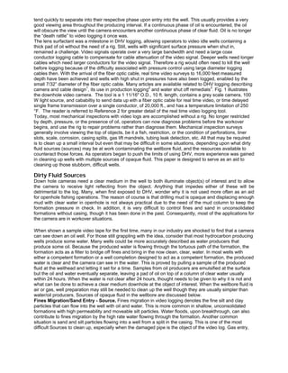
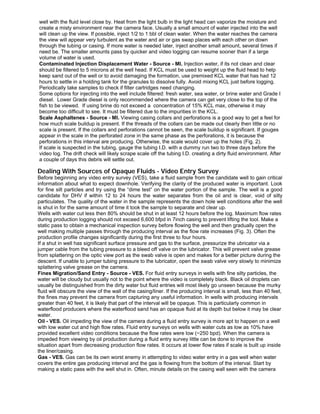
. Fig. 1 illustrates
the downhole video camera. The tool is a 1 11/16" O.D., 10 ft. length, contains a grey scale camera, 100
W light source, and cababiltiy to send data up eith a fiber optic cable for real time video, or time delayed
single frame transmission over a single conductor, of 20,000 ft., and has a temperature limitation of 250
°F. The reader is referred to Reference 2 for greater detail of the real time video logging tool.
Today, most mechanical inspections with video logs are accomplished without a rig. No longer restricted
by depth, pressure, or the presence of oil, operators can now diagnose problems before the workover
begins, and use the rig to repair problems rather than diagnose them. Mechanical inspection surveys
generally involve viewing the top of objects, be it a fish, restriction, or the condition of perforations, liner
slots, scale, corrosion, casing splits, gas lift mandrels, tubing leak detection, etc. All that may be required
is to clean up a small interval but even that may be difficult in some situations, depending upon what dirty
fluid sources (sources) may be at work contaminating the wellbore fluid, and the resources available to
counteract those forces. As operators began to push the limits of using DHV, more experience was gained
in cleaning up wells with multiple sources of opaque fluid. This paper is designed to serve as an aid to
cleaning up those stubborn, difficult wells.
Dirty Fluid Sources
Down hole cameras need a clear medium in the well to both illuminate object(s) of interest and to allow
the camera to receive light reflecting from the object. Anything that impedes either of these will be
detrimental to the log. Many, when first exposed to DHV, wonder why it is not used more often as an aid
for openhole fishing operations. The reason of course is that drilling mud is opaque and displacing enough
mud with clear water in openhole is not always practical due to the need of the mud column to keep the
formation pressure in check. In addition, it is very difficult to control fines and sand in unconsolidated
formations without casing, though it has been done in the past. Consequently, most of the applications for
the camera are in workover situations.
When shown a sample video tape for the first time, many in our industry are shocked to find that a camera
can see down an oil well. For those still grappling with the idea, consider that most hydrocarbon producing
wells produce some water. Many wells could be more accurately described as water producers that
produce some oil. Because the produced water is flowing through the tortuous path of the formation, the
formation acts as a filter to bridge off fines and bring in the now clean, clear, water. In most wells with
either a competent formation or a well completion designed to act as a competent formation, the produced
water is clear and the camera can see in the water. This is proved by pulling a sample of the produced
fluid at the wellhead and letting it set for a time. Samples from oil producers are emulsified at the surface
but the oil and water eventually separate, leaving a pad of oil on top of a column of clear water usually
within 24 hours. When the water is not clear after 24 hours, thought needs to be given to why it is not and
what can be done to achieve a clear medium downhole at the object of interest. When the wellbore fluid is
air or gas, well preparation may still be needed to clean up the well though they are usually simpler than
water/oil producers. Sources of opaque fluid in the wellbore are discussed below.
Fines Migration/Sand Entry - Source. Fines migration in video logging denotes the fine silt and clay
particles that can flow into the well with oil and water. This is more common in shallow, unconsolidated
formations with high permeability and moveable silt particles. Water floods, upon breakthrough, can also
contribute to fines migration by the high rate water flowing through the formation. Another common
situation is sand and silt particles flowing into a well from a split in the casing. This is one of the most
difficult Sources to clean up, especially when the damaged pipe is the object of the video log. Gas entry,
discussed later, is another difficult Source, and the two in combination can be “fatal” in attempting to video
log a well.
Fines and sand are differentiated by their grain size. If the water column is not clear and there is no oil,
gas, or individual sand particles floating around, then it is reasonable to assume the water is holding fine
silt particles in suspension. Some sand types are very small and are also held in suspension. Larger sand
grains, having more weight, are easier to deal with since gravity will draw the grains to bottom. Both fines
and sand entry can be very difficult to clean up depending upon the volume produced and the type of
sand. Various factors influence the effect silt and sand will have on the video log. For example, larger
casing/liner sizes are more difficult to clean up to view holes, slots, etc., because of the volume required to
displace fluid. Also, with the camera centered in the well, the wall of the pipe is further away from the
camera and, in dirty fluid, would be harder to see. Smaller casing allows the camera to be closer to the
wall of the pipe so it has a greater chance of seeing a hole or eroded slot.
Oil - Source. The lens surfactant, as discussed in the Background section of this paper, makes well
preparation much easier in oil producers. Oil is generally only a problem when it is the continuous phase
fluid and the object of interest is in that interval. When the object of interest is in the tubing of a producing
well, plans should be made in advance to prepare to clean up the tubing string with filtered water or gas
before video logging if possible.
Although the lens surfactant prevents oil from sticking to the lens, occasionally tiny oil droplets get trapped
on the flat face of the optic view port in front of the lens. When this happens, the logging crew usually
need only accelerate the tool up or down in water to clear the lens. However, it may be difficult to clean the
camera when there is little rat hole filled with water below the fluid oil/water contact. This practice of
accelerating the tool may take anywhere from 10 ft. to 100 ft. to do the job. Gas flowing past the optic view
port can also help clear the oil off the lens in this situation.
Gas - Source. Gas wells are usually not designed to handle large water production because when
combined with liquids, gas corrodes and wears down the tubulars and production casing much sooner
than a well producing all liquid or all dry gas. Therefore we find fewer mechanical problems associated
with gas wells and most video logs in gas wells are for water entry identification when conventional
production logs have difficulty finding water entry. An example of mechanical inspection for a gas well may
be for identifying sand entry in dry gas wells where the flow rate is so high it brings in sand and begins to
pit and erode the subsurface and surface tubulars. This is common in gas storage reservoirs where the
operator may be interested in a visual inspection of slotted liner and perforations to look for evidence of
sand blasting/erosion on the production casing. Dry gas flowing into a dry gas well will provide a clear
wellbore and virtually no well preparation is necessary other than routine planning for pressure control and
checking minimum restrictions, etc.
Gas becomes a Source in two situations. First, when wet gas is flowing into the well above the fluid level
and the object of interest is above the fluid level. This effect is much like driving in fog at night, in that
bright lights do not provide much distance viewing in the fog and its difficult to see very far. Details of the
tubulars, casing wall, perforations, etc., may be difficult to see.
The second situation occurs when gas enters the well in the water column and the object of interest is in
this gaseous/water interval. Gas stirs up particulates that otherwise would settle out and fall to bottom.
And in volumes greater than 50 mcf/day and production casing less than 7 inch O.D., gas can block the
view of the camera because of the white turbulence created by the gas flowing through water. This effect
is much like compressed air blowing into a spa. The white bubbles of air can be seen but not what is
behind the bubbles.
Contaminated Injection Water - Source. Contaminated injection water, for this paper, includes both
water injected into injection wells and water injected into producer wells to clean up a Source. Much like
an electronic technician must have good test instruments to troubleshoot and repair equipment, video
logging requires its “test equipment” (the displacement fluid) be in “working order” (clean and clear).
Trying to counter one Source while creating another makes for long, arduous, jobs. Unfortunately, this
situation often occurs for operators attempting DHV their first time. When recommended procedures are
not followed, results are usually poor. Production workover personnel must understand that the adage “oil
field clean” does not apply to DHV logging. Clean injection or displacement water means water with the
same clarity of water filtered through a five-micron filter, at the well head, not where the vacuum truck
collected it.
All of the above also holds true for injection wells. Injectors are clean and clear when the injection fluid is
clean and clear. Injection water that contains minerals or ions that can precipitate into scale downhole may
be difficult to see through. Sample injection water periodically at the wellhead to see what is actually being
injected into the well. Water flowing from a hose can look deceivingly clear, but might not pass the “dime
test.” The dime test involves viewing a dime through a four inch tall column of the water being injected.
The adage of the dime test is “If you can’t see the dime, you are wasting your time.” I.e., the water being
injected is not going to provide a clear enough medium to see through. The measure of how well the
details on the dime show through the water sample is a measure of how well the camera will see details
along the casing wall in the well. Understand that injection water may be clean at the source but by the
time it makes its way through surface piping or sloshed around in vacuum trucks, it may have collected oil,
drilling mud, or other contaminates and impurities in enough concentrations to cloud the water.
Scale/Asphaltenes - Source. The presence of a scale buildup is associated with the presence of water
production and/or water injection. Fields under waterflood usually have significant problems with scale.
Sometimes it can get so thick it chokes off production in some producers. A previous paper describes the
use of the video log and the presence of scale in selecting WSO intervals.
3
Scale effects video logs by its color and by its amount. If the scale is white, it will reflect light providing
better light conditions downhole. However, if the scale is black from an asphaltene coating or other
wellbore contaminates, it will absorb the light making it difficult to see anything. As the scale (white or
dark) builds up it decreases the I.D. of the pipe. This can result in “black out” intervals in which the oil and
gas, instead of making their way to the high side of the well, are now forced right into the path of the
camera obscuring the video images.
Dealing With Sources of Opaque Fluids For Mechanical Inspection
Most mechanical inspections (MI) with DHV do not involve workover rigs as previous mentioned. When
the camera is requested on a well with a workover rig, it most often involves a problem with casing that
has lost it's integrity. Once a rig stirs up the well with tubing movement, rods pulled, etc., it is sure to
create a dirty murky fluid from oil, scale, pipe dope, etc. If the fluid level is lower than the interval to
inspect, the camera could be called into video log the well. If the interval to inspect is below the fluid level,
pump in clean water to displace the murky well fluid. A pump-in-tee and packoff should be included in the
rig up to allow for injecting water while the camera is in the well.
If the operator moves the rig off with the intent to deploy DHV later, they typically place a kill string in the
well. In that case the well should be prepared as follows:
•position the bottom of the kill string within two to ten feet of the interval to be viewed, the closer the better;
•circulate or inject three tubing volumes of clean water down the kill string;
•move off and wait at least one to two weeks before running the camera to allow particulates to settle out.
For non rig situations if the wells have surface pressure then pressure conrol equipment should be
employed to control the well. Otherwise a pump-in-tee and packoff should also be included in a non-rig
idle well (no surface pressure) situation, if clean water is available for the option of injecting clean water
down the workstring to clean up the well. It may be necessary to inject (bullhead) water into the formation.
This requires open perforations or slots or a hole to displace the dirty wellbore fluid back into the
formation. In fields with substantial depletion and high permeability, wells tend to go on vacuum after
enough water is injected allowing for high injection rates and rapid cleaning of the tubing and production
casing. Bullheading water in wells with low permeability or plugged perforations or slots, etc., may be a
slow arduous process for it may take up to three tubing volumes or more to clean up an area just below
the tubing.
The injection fluid will also go into the highest permeability intervals. If those intervals happen to be
shallow and the interval of interest is deep, bullheading may do absolutly nothing to clean up below the
high permeability intervals. The better solution may be to get the rig back on and circulate with a
workstring. Also, injecting into low permeability formation charges the formation and it will release fluid
back into the well to relieve pressure when the surface pressure is bled off. A hole or split with sand entry
will then blow in more sand from the higher pressure in the formation (the proverbial two steps forward,
three steps back approach.) The surface pressure must be maintained in this situation to get the log.
When displacing opaque wellbore fluid with water is necessary, operators must do their part to ensure
successful video logs. Their part consists of, but is not limited to, providing clean displacement fluid and a
reasonably clean, intact (no holes or leaks) tubing or workstring (unless the tubing is the object to be
inspected with known leaks or problems.) If the tubing unknowingly has holes in it, tremendous amounts
of water could be injected trying to clean up a well that might not ever clean up. If the tubing tail will not
clean up after three tubing volumes of injected water, its time to start suspecting a tubing leak bringing in
oil or dirty water from the back side being drawn in by the flow down. One technique to try is to pressure
up the backside to the same pressure as the tubing. To find the leak, over pressure the backside and
force the backside fluid into the tubing. If the tool is in clean water, gas, or air, the leak will be identifiable.
If the work involves a rig, the tubing should be pulled and replaced with a clean, tested string. Continue
checking the condition of the injection water. It must be clean and checked as close to the well head as
possible. Try to avoid using kelly hoses, they are often filled with material drawn off into the well as the
water is injected. Also, avoid coated tubing as a workstring if possible, it can shed off plastic particles and
obscure the area when the pump rate is increased.
There is no hard and fast rule regarding how low or thick to expect the oil pad to be on a shut in well
before video logging. Wells with watercuts of 10% can be all water over the perforation interval if the total
flow rate is small. If the objective is a mechanical inspection and the well is an active producer, the
simplest approach is to shut the well in for at least the same amount of time as it takes for the water in a
fluid sample from the well to clear up. If that is still insufficient then injecting clean water or nitrogen
should be injected to displace the dirty fluid.
Fines Migration/Sand Entry - Source - MI.
Cameras are often used in wells with sand problems to help understand the casing damage when a split
is suspected. The best approach is for a workover rig to position an open ended workstring two feet
below the suspected damage and displace the dirty fluid with clean water continuously while the camera
descends through the tubing string and out the tubing tail. Returns should not be reinjected. The five
micron filters will clog and need changing too often. Rig hands should dope the pins of the workstring, not
the boxes. This eliminates pipe dope from smearing on the optic view port on the way down the tubing. If
the rig is using 2 3/8" tubing, install a joint of 2 7/8" on the bottom. High pump rates tend to shake and
rattle the camera and the 100 watt halogen bulb is sensitive to excessive vibration because the filament
heats to 1300°C and the camera can safely reside in the larger I.D. of the 2 7/8" joint should the pump
rate need to be increased to five bbls/min or more.
Hang the upper sheave wheel in the derrick so the blocks can be free to raise and lower the tubing tail to
different depths. Pump three tubing volumes of fluid, typical pump rates are one to five barrels per
minute. Stop injection, go in with the camera maintaining a one half to one barrel per minute rate. Once
the camera is out of the tubing and visibility is established, raise the tubing several feet and follow up with
the camera until the desired interval of interest is logged. If the tubing cannot come up high enough to
continue the video, pull out of the hole with the camera and remove one stand of tubing. Then go back in
with the camera. Repeat the process until the desired interval is logged.
These operations can take hours to clean up enough to see the damage and gauge its extent.
Experimenting with closing in the backside while pumping down the workstring can help. Casing splits
with sand entry probably are the most difficult wells to prep for video logging.
Oil - Source - MI. While the lens surfactant prevents oil from sticking to the lens, it cannot improve the
camera's ability to see through either a continuous fluid phase of oil or opaque, dirty water. The surfactant
allows the camera to pass through oil and avoid the former necessity of continuously injecting water to
keep oil from contacting the lens. This liberty opened the door to non rig work and often no preparation
would be necessary if the pad of oil did not occur in the interval of interest. That may or may not be a
problem depending on what is needed to be viewed. If the object of interest is on or near bottom then,
depending on the oil/water cut, production volumes, and how long the well has been static, a column of
clear water could be over the interval of interest. However, even high water cut wells idle for over a year
can have the entire fluid column full of oil that has displaced the water via crossflow. In those cases, the
oil must be lifted out or injected back into the formation. If the objective is to view the tubing, then injection
filtered water is preferable. If the objective is to view the casing wall below the tubing and oil is expected
to cover the interval of interest once the well is shut in, then flow it out. and the preferable way is to flow
the oil out under the production scheme. This allows the produced water that is usually clean to displace
the oil and not a murky surface fluid. Tripping pipe should be avoided as it usually dirties up the well bore
water.
Gas - Source - MI. If the goal is to make a mechanical inspection on a well that produces oil and a gas
volume greater than 100 mcf/day, then it is best to shut the well in one day ahead of time to keep
pressure on the formation so as not to produce the gas and use pressure control equipment as needed.
In wells with sand particulates and gas that cannot be shut off, the well fluid will be very cloudy down to
the gas entry point and then clear just a few feet deeper. The smaller the casing size the worse the gas
effect is because it begins to move right into the path of the lens instead of taking the high side of the
well. When high volume gas rates are flowing through a water column, the video received becomes
turbulent, and only the deepest gas entry can be identified as the effect diminishes deeper in the well.
Also, if the well produces gas it is probably best to shut-in to reduce the gas production. Deploy pressure
control equipment if the well develops surface pressure. Avoid releasing the surface pressure during rig
up to keep the gas in the formation.
When the gas is wet, however, it can appear misty and fog like above the fluid level. In the tubing this is
usually not a problem since the wall of the pipe is so close to the camera, but in the casing the effect can
make it difficult to see objects. The easiest solution is to dip the camera into the fluid, even oil to wipe off
the condensation. What can sometimes also be a problem is moisture along the tubing/casing wall in a
well with the fluid level close by. Heat from the light bulb in the light head can vaporize the moisture and
create a misty environment near the camera face. Usually a small amount of water injected into the well
will clean up the view. If possible, inject 1/2 to 1 bbl of clean water. When the water reaches the camera
the view will appear very turbulent as the water and air or gas swap places with each other on down
through the tubing or casing. If more water is needed later, inject another small amount, several times if
need be. The smaller amounts pass by quicker and video logging can resume sooner than if a large
volume of water is used.
Contaminated Injection Displacement Water - Source - MI. Injection water, if its not clean and clear
should be filtered to 5 microns at the well head. If KCL must be used to weight up the fluid head to help
keep sand out of the well or to avoid damaging the formation, use premixed KCL water that has had 12
hours to settle in a holding tank for the granules to dissolve fully. Avoid mixing KCL just before logging.
Periodically take samples to check if filter cartridges need changing.
Some options for injecting into the well include filtered: fresh water, sea water, or brine water and Grade I
diesel. Lower Grade diesel is only recommended where the camera can get very close to the top of the
fish to be viewed. If using brine do not exceed a concentration of 15% KCL max, otherwise it may
become too difficult to see. It must be filtered due to the impurities in the KCL.
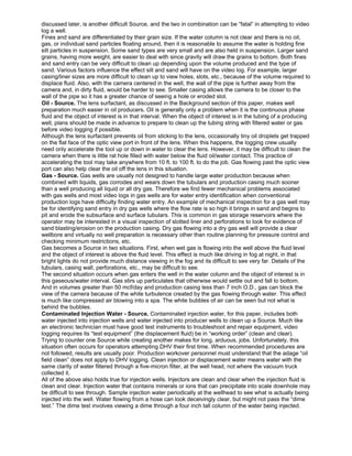
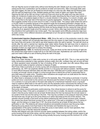
Scale Asphaltenes - Source - MI. Viewing casing collars and perforations is a good way to get a feel for
how much scale buildup is present. If the threads of the collars can be made out clearly then little or no
scale is present. If the collars and perforations cannot be seen, the scale buildup is significant. If gouges
appear in the scale in the perforated zone in the same phase as the perforations, it is because the
perforations in this interval are producing. Otherwise, the scale would cover up the holes (Fig. 2).
If scale is suspected in the tubing, gauge the tubing I.D. with a dummy run two to three days before the
video log. The drift check will likely scrape scale off the tubing I.D. creating a dirty fluid environment. After
a couple of days this debris will settle out.
Dealing With Sources of Opaque Fluids - Video Entry Survey
Before beginning any video entry survey (VES), take a fluid sample from the candidate well to gain critical
information about what to expect downhole. Verifying the clarity of the produced water is important. Look
for fine silt particles and try using the “dime test” on the water portion of the sample. The well is a good
candidate for DHV if within 12 to 24 hours the water separates from the oil and is clear, void of silty
particulates. The quality of the water in the sample represents the down hole well conditions after the well
is shut in for the same amount of time it took the sample to separate and clear up.
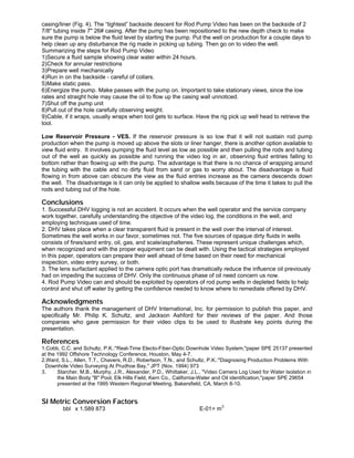
Wells with water cut less then 80% should be shut in at least 12 hours before the log. Maximum flow rates
during production logging should not exceed 6,600 bfpd in 7inch casing to prevent lifting the tool. Make a
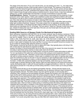
static pass to obtain a mechanical inspection survey before flowing the well and then gradually open the
well making multiple passes through the producing interval as the flow rate increases (Fig. 3). Often the
production profile changes significantly during the first three to four hours.
If a shut in well has significant surface pressure and gas to the surface, pressurize the ubricator via a
jumper cable from the tubing pressure to a bleed off valve on the lubricator. This will prevent valve grease
from splattering on the optic view port as the swab valve is open and makes for a better picture during the
descent. If unable to jumper tubing pressure to the lubricator, open the swab valve very slowly to minimize
splattering valve grease on the camera.
Fines Migration/Sand Entry - Source - VES. For fluid entry surveys in wells with fine silty particles, the
water will be cloudy but usually not to the point where the video is completely black. Black oil droplets can
usually be distinguished from the dirty water but fluid entries will most likely go unseen because the murky
fluid will obscure the view of the wall of the casing/liner. If the producing interval is small, less than 40 feet,
the fines may prevent the camera from capturing any useful information. In wells with producing intervals
greater than 40 feet, it is likely that part of the interval will be opaque. This is particularly common in
waterflood producers where the waterflood sand has an opaque fluid at its depth but below it may be clear
water.
Oil - VES. Oil impeding the view of the camera during a fluid entry survey is more apt to happen on a well
with low water cut and high flow rates. Fluid entry surveys on wells with water cuts as low as 10% have
provided excellent video conditions because the flow rates were low (~250 bpd). When the camera is
impeded from viewing by oil production during a fluid entry survey little can be done to improve the
situation apart from decreasing production flow rates. It occurs at lower flow rates if scale is built up inside
the liner/casing.
Gas - VES. Gas can be its own worst enemy in attempting to video water entry in a gas well when water
covers the entire gas producing interval and the gas is flowing from the bottom of the interval. Start by
making a static pass with the well shut in. Often, minute details on the casing wall seen with the camera
that can flag the source of water entry without ever flowing the well. Details such as a shiny spot on the
casing across from a perforation can be evidence of water and sand entry. After a thorough static pass
has been logged, the well can be flowed but should begin at a very low rate. Make the first flowing pass
with the well just beginning to flow. Multiple passes are then made at higher and higher flow rates.
Opening the well up too fast can bring in sand and fines and cloud up the water and may take time to
settle out. Evidence of water entry is found by either the water disturbing the flow of sand near bottom or
when the gas or oil suddenly begins to flow in a circular direction in the casing. In a column of water, gas
and oil only flow to the high side of the hole due to gravity segregation. Therefore, any other direction of
flow suggests another force at work and if it is clear, it must be water. The reason water enters the well in
a circular motion is probably because of the apparent angle the eccentered perforation charges had as
they fired into curved casing. Perforating guns are usually shot eccentered for maximum penetration and
unless the gun is zero degree phasing and the shots are facing straight into the casing the holes will exit
the casing at an apparent angle since the casing is curved. Some video logs have documented different
flow directions from perforations two inches apart. This may explain some difficulty production logs have
as water comes in from different directions and attempts to turn the spinner blades in opposite directions
within two inches.
Contaminated Injection Displacement Water - VES. Since the well is in the production mode for video
entry surveys, injection will not typically take place and the only reason to inject water is because there are
two many fines and sands in the well to see what happens when the well is opened. The well will cloud up
shortly after the well is opened but injecting clean water before flowing the well buys time to observe a
particular event when the well is brought on. Water flowing through a bridge plug on bottom could be an
example of when you might want to employ this strategy.
Scale/Asphaltenes - VES. As mentioned previously, scale can block out the view by forcing oil right into
the camera face when there is scale built up on the wall of the pipe. Asphaltenes can coat the wall of the
pipe and make it difficult to see oil flowing along the wall of the pipe.
Rod Pump Video - VES
Rod Pump Video denotes a video entry survey on a rod pump well with DHV. This is a new service that
holds tremendous potential to help operators achieve water shut offs, confident they will not shut off their
oil. Most operators resist remedials for fear of shutting off the oil yet water shut offs reduce lifting costs
and help avoid costly re-injection schemes to dispose of water.
Rod Pump Video is primarily an oil entry survey with simultaneous mechanical inspection of slots,
perforations, etc. DHV can positively identify oil entry in a rod pump well without question. Identifying water
is more difficult because total flow rates are often less than 1500 bfpd and if a large interval is open, there
is simply not enough volume of water in a short enough time to disturb the oil flow or particulate flow to
give itself away as a water entry. Therefore other indications are sought such as scale above the interval,
sand entry, or enlarged slots or perforations.
An offset head is necessary to enter the well from the backside. Also, if the tubing is anchored, it must be
pulled and rerun unanchored so the camera can descend past the bottom of tubing. It would be unusual to
run a camera in a rod pump well on the back side solely for a mechanical inspection since a rig would
need to install an offset head on the well for entry into the backside and/or unanchored the tubing if it was
anchored. It would make more sense to pull the rods and tubing and use a workstring to clean up the well
at the depth of interest.
Rod pump videos require particularly careful planning. One critical decision is where to set the pump for
the Rod Pump Video. If the well is completed in 5 1/2 inch liner or smaller, the decision is already partially
made in that the pump needs to be set at least 30 feet above the liner top because the annular space is
too small to fit the tool and the tubing in the liner. That may be a problem in low pressure reservoirs where
the fluid level may not get up to the pump (there is an option discussed at the end of this section). The
operator should consider a fluid level survey before preparing the well if those concerns exist, however,
the camera has shown fluid level surveys to be in gross error. If the well is completed in 7 inch casing or
larger, and the tubing is no larger than 2 7/8", the pump should be set at least 30 feet above the top
perforation or slot. This distance will reduce turbulence and possible emulsions near the pump intake.
Raising the pump places more fluid head on the formation and therefore the log is not a true
representation of the same conditions as when the pump is near bottom, but for most operators, Rod
Pump Video is one of the few resources available.
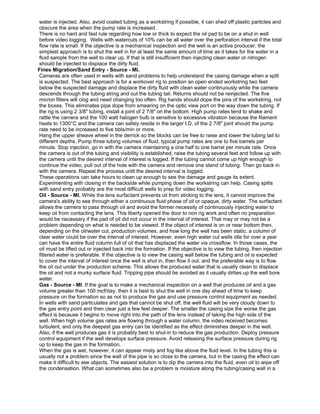
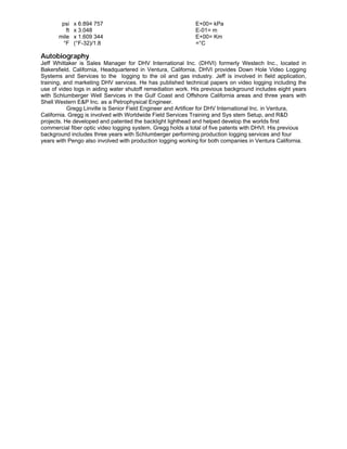
Review well diagram and note minimum annular space available between the tubing collars, and/or the
pump housing at the tail of the tubing, and the casing or liner. There must be enough annular space to get
the tool past the largest O.D. on the tubing string (usually the pump housing) and the minimum I.D. of the
casing/liner (Fig. 4). The “tightest” backside descent for Rod Pump Video has been on the backside of 2
7/8" tubing inside 7" 26# casing. After the pump has been repositioned to the new depth check to make
sure the pump is below the fluid level by starting the pump. Put the well on production for a couple days to
help clean up any disturbance the rig made in picking up tubing. Then go on to video the well.
Summarizing the steps for Rod Pump Video
1)Secure a fluid sample showing clear water within 24 hours.
2)Check for annular restrictions
3)Prepare well mechanically
4)Run in on the backside - careful of collars.
5)Make static pass.
6)Energize the pump. Make passes with the pump on. Important to take stationary views, since the low
rates and straight hole may cause the oil to flow up the casing wall unnoticed.
7)Shut off the pump unit
8)Pull out of the hole carefully observing weight.
9)Cable, if it wraps, usually wraps when tool gets to surface. Have the rig pick up well head to retrieve the
tool.
Low Reservoir Pressure - VES. If the reservoir pressure is so low that it will not sustain rod pump
production when the pump is moved up above the slots or liner hanger, there is another option available to
view fluid entry. It involves pumping the fluid level as low as possible and then pulling the rods and tubing
out of the well as quickly as possible and running the video log in air, observing fluid entries falling to
bottom rather than flowing up with the pump. The advantage is that there is no chance of wrapping around
the tubing with the cable and no dirty fluid from sand or gas to worry about. The disadvantage is fluid
flowing in from above can obscure the view as the fluid entries increase as the camera descends down
the well. The disadvantage is it can only be applied to shallow wells because of the time it takes to pull the
rods and tubing out of the hole.
Conclusions
1. Successful DHV logging is not an accident. It occurs when the well operator and the service company
work together, carefully understanding the objective of the video log, the conditions in the well, and
employing techniques used of time.
2. DHV takes place when a clear transparent fluid is present in the well over the interval of interest.
Sometimes the well works in our favor, sometimes not. The five sources of opaque dirty fluids in wells
consists of fines/sand entry, oil, gas, and scale/asphaltenes. These represent unique challenges which,
when recognized and with the proper equipment can be dealt with. Using the tactical strategies employed
in this paper, operators can prepare their well ahead of time based on their need for mechanical
inspection, video entry survey, or both.
3. The lens surfactant applied to the camera optic port has dramatically reduce the influence oil previously
had on impeding the success of DHV. Only the continuous phase of oil need concern us now.
4. Rod Pump Video can and should be exploited by operators of rod pump wells in depleted fields to help
control and shut off water by getting the confidence needed to know where to remediate offered by DHV.
Acknowledgments
The authors thank the management of DHV International, Inc. for permission to publish this paper, and
specifically Mr. Philip K. Schultz, and Jackson Ashford for their reviews of the paper. And those
companies who gave permission for their video clips to be used to illustrate key points during the
presentation.
References
1.Cobb, C.C. and Schultz, P.K.:"Real-Time Electo-Fiber-Optic Downhole Video System,"paper SPE 25137 presented
at the 1992 Offshore Technology Conference, Houston, May 4-7.
2.Ward, S.L., Allen, T.T., Chavers, R.D., Robertson, T.N., and Schultz, P.K.:"Diagnosing Production Problems With
Downhole Video Surveying At Prudhoe Bay," JPT (Nov. 1994) 973
3. Starcher, M.B., Murphy, J.R., Alexander, P.D., Whittaker, J.L., "Video Camera Log Used for Water Isolation in
the Main Body "B" Pool, Elk Hills Field, Kern Co., California-Water and Oil identification,"paper SPE 29654
presented at the 1995 Western Regional Meeting, Bakersfield, CA, March 8-10.
SI Metric Conversion Factors
bbl x 1.589 873 E-01= m
3
psi x 6.894 757 E+00= kPa
ft x 3.048 E-01= m
mile x 1.609 344 E+00= Km
°F (°F-32)/1.8 =°C
Autobiography
Jeff Whittaker is Sales Manager for DHV International Inc. (DHVI) formerly Westech Inc., located in
Bakersfield, California, Headquartered in Ventura, California, DHVI provides Down Hole Video Logging
Systems and Services to the logging to the oil and gas industry. Jeff is involved in field application,
training, and marketing DHV services. He has published technical papers on video logging including the
use of video logs in aiding water shutoff remediation work. His previous background includes eight years
with Schlumberger Well Services in the Gulf Coast and Offshore California areas and three years with
Shell Western E&P Inc. as a Petrophysical Engineer.
Gregg Linville is Senior Field Engineer and Artificer for DHV International Inc. in Ventura,
California. Gregg is involved with Worldwide Field Services Training and Sys stem Setup, and R&D
projects. He developed and patented the backlight lighthead and helped develop the worlds first
commercial fiber optic video logging system. Gregg holds a total of five patents with DHVI. His previous
background includes three years with Schlumberger performing production logging services and four
years with Pengo also involved with production logging working for both companies in Ventura California.

More Related Content

What's hot

Rope Access: Avoiding Spills into Navigable Waters
Rope Access: Avoiding Spills into Navigable WatersRope Access: Avoiding Spills into Navigable Waters
Rope Access: Avoiding Spills into Navigable WatersQualSpec
 
Horizontal Remediation Wells - The Straight Skinny on Drilling Muds
Horizontal Remediation Wells - The Straight Skinny on Drilling MudsHorizontal Remediation Wells - The Straight Skinny on Drilling Muds
Horizontal Remediation Wells - The Straight Skinny on Drilling MudsDirectional Tech
 
ITIKI's Water Safety Plan
ITIKI's Water Safety PlanITIKI's Water Safety Plan
ITIKI's Water Safety PlanLynda Shelley
 
The Case for Point-of-Sale Dawn Struse Long
The Case for Point-of-Sale Dawn Struse LongThe Case for Point-of-Sale Dawn Struse Long
The Case for Point-of-Sale Dawn Struse LongDawnLong18
 
Hyde marine gold presentation
Hyde marine gold presentationHyde marine gold presentation
Hyde marine gold presentationMuhamad Talib
 
HPHT WELL ENGINEERING
HPHT   WELL ENGINEERINGHPHT   WELL ENGINEERING
HPHT WELL ENGINEERINGpetroEDGE
 
Business Case - H2FLOW
Business Case - H2FLOWBusiness Case - H2FLOW
Business Case - H2FLOWPeter L. Blaha
 
Garbage disposal part ii
Garbage disposal part   iiGarbage disposal part   ii
Garbage disposal part iianchorsewar02
 
Nightmare of Hydrate Blockages: How to Remove them Safely and Efficiently
Nightmare of Hydrate Blockages: How to Remove them Safely and EfficientlyNightmare of Hydrate Blockages: How to Remove them Safely and Efficiently
Nightmare of Hydrate Blockages: How to Remove them Safely and EfficientlyHassan Karimaie
 
Water tight integrity surveys, inspections & repair brochure v8
Water tight integrity surveys, inspections & repair brochure v8Water tight integrity surveys, inspections & repair brochure v8
Water tight integrity surveys, inspections & repair brochure v8SteveFarries
 
Hydraulic frac webinar
Hydraulic frac webinarHydraulic frac webinar
Hydraulic frac webinarPetroTeach1
 
O&GFaclities_Oct2013_SandManagementMethodologies
O&GFaclities_Oct2013_SandManagementMethodologiesO&GFaclities_Oct2013_SandManagementMethodologies
O&GFaclities_Oct2013_SandManagementMethodologiesHank Rawlins
 

What's hot (16)

Rope Access: Avoiding Spills into Navigable Waters
Rope Access: Avoiding Spills into Navigable WatersRope Access: Avoiding Spills into Navigable Waters
Rope Access: Avoiding Spills into Navigable Waters
 
Horizontal Remediation Wells - The Straight Skinny on Drilling Muds
Horizontal Remediation Wells - The Straight Skinny on Drilling MudsHorizontal Remediation Wells - The Straight Skinny on Drilling Muds
Horizontal Remediation Wells - The Straight Skinny on Drilling Muds
 
ITIKI's Water Safety Plan
ITIKI's Water Safety PlanITIKI's Water Safety Plan
ITIKI's Water Safety Plan
 
The Case for Point-of-Sale Dawn Struse Long
The Case for Point-of-Sale Dawn Struse LongThe Case for Point-of-Sale Dawn Struse Long
The Case for Point-of-Sale Dawn Struse Long
 
Hyde marine gold presentation
Hyde marine gold presentationHyde marine gold presentation
Hyde marine gold presentation
 
HPHT WELL ENGINEERING
HPHT   WELL ENGINEERINGHPHT   WELL ENGINEERING
HPHT WELL ENGINEERING
 
Nassau Case Study-New Brand
Nassau Case Study-New BrandNassau Case Study-New Brand
Nassau Case Study-New Brand
 
Waterflood Design and Operational Best Practices
Waterflood Design and Operational Best PracticesWaterflood Design and Operational Best Practices
Waterflood Design and Operational Best Practices
 
Business Case - H2FLOW
Business Case - H2FLOWBusiness Case - H2FLOW
Business Case - H2FLOW
 
Garbage disposal part ii
Garbage disposal part   iiGarbage disposal part   ii
Garbage disposal part ii
 
Nightmare of Hydrate Blockages: How to Remove them Safely and Efficiently
Nightmare of Hydrate Blockages: How to Remove them Safely and EfficientlyNightmare of Hydrate Blockages: How to Remove them Safely and Efficiently
Nightmare of Hydrate Blockages: How to Remove them Safely and Efficiently
 
Water tight integrity surveys, inspections & repair brochure v8
Water tight integrity surveys, inspections & repair brochure v8Water tight integrity surveys, inspections & repair brochure v8
Water tight integrity surveys, inspections & repair brochure v8
 
Hydraulic frac webinar
Hydraulic frac webinarHydraulic frac webinar
Hydraulic frac webinar
 
Lean - Tight Oil Design & Construction
Lean - Tight Oil Design & ConstructionLean - Tight Oil Design & Construction
Lean - Tight Oil Design & Construction
 
Tank Cleaning with BioSolve
Tank Cleaning with BioSolveTank Cleaning with BioSolve
Tank Cleaning with BioSolve
 
O&GFaclities_Oct2013_SandManagementMethodologies
O&GFaclities_Oct2013_SandManagementMethodologiesO&GFaclities_Oct2013_SandManagementMethodologies
O&GFaclities_Oct2013_SandManagementMethodologies
 

Viewers also liked

2.enfoque sistémico
2.enfoque sistémico2.enfoque sistémico
2.enfoque sistémicoalexisbeco159
 
Comunicación organizacional
Comunicación organizacionalComunicación organizacional
Comunicación organizacionalLilibeth Portugal
 
La funcion social de las organizaciones
La funcion social de las organizacionesLa funcion social de las organizaciones
La funcion social de las organizacionespaneluda
 
Alta dirección: Herramientas para aplicar el enfoque sistémico
Alta dirección: Herramientas para aplicar el enfoque sistémicoAlta dirección: Herramientas para aplicar el enfoque sistémico
Alta dirección: Herramientas para aplicar el enfoque sistémicoHéctor Debernardo
 
Curso de diseño organizacional y procesos / Sesiones I - II - III - Exposito...
Curso de diseño organizacional y procesos / Sesiones I - II - III - Exposito...Curso de diseño organizacional y procesos / Sesiones I - II - III - Exposito...
Curso de diseño organizacional y procesos / Sesiones I - II - III - Exposito...Rafael Trucios Maza
 
Organizational Communication
Organizational CommunicationOrganizational Communication
Organizational Communicationamanideutsch
 
Funciones de las organizaciones
Funciones de las organizacionesFunciones de las organizaciones
Funciones de las organizacionesfiaka
 
Organizational communication
Organizational communicationOrganizational communication
Organizational communicationNingsih SM
 

Viewers also liked (11)

Enfoque sistemico
Enfoque sistemicoEnfoque sistemico
Enfoque sistemico
 
2.enfoque sistémico
2.enfoque sistémico2.enfoque sistémico
2.enfoque sistémico
 
Comunicación organizacional
Comunicación organizacionalComunicación organizacional
Comunicación organizacional
 
La funcion social de las organizaciones
La funcion social de las organizacionesLa funcion social de las organizaciones
La funcion social de las organizaciones
 
Alta dirección: Herramientas para aplicar el enfoque sistémico
Alta dirección: Herramientas para aplicar el enfoque sistémicoAlta dirección: Herramientas para aplicar el enfoque sistémico
Alta dirección: Herramientas para aplicar el enfoque sistémico
 
Curso de diseño organizacional y procesos / Sesiones I - II - III - Exposito...
Curso de diseño organizacional y procesos / Sesiones I - II - III - Exposito...Curso de diseño organizacional y procesos / Sesiones I - II - III - Exposito...
Curso de diseño organizacional y procesos / Sesiones I - II - III - Exposito...
 
Organizational Communication
Organizational CommunicationOrganizational Communication
Organizational Communication
 
Diseño Organizacional
Diseño OrganizacionalDiseño Organizacional
Diseño Organizacional
 
Funciones de las organizaciones
Funciones de las organizacionesFunciones de las organizaciones
Funciones de las organizaciones
 
Etapas de la organizacion
Etapas de la organizacionEtapas de la organizacion
Etapas de la organizacion
 
Organizational communication
Organizational communicationOrganizational communication
Organizational communication
 

Similar to Well Preparation Essential for Successful Video Logging

Application of intelligent well completion in optimizing production
Application of intelligent well completion in optimizing productionApplication of intelligent well completion in optimizing production
Application of intelligent well completion in optimizing productionChirag Vanecha
 
Spe26043 (fluid entry)
Spe26043 (fluid entry)Spe26043 (fluid entry)
Spe26043 (fluid entry)Gregg Linville
 
SPE26043 (Fluid Entry)
SPE26043 (Fluid Entry)SPE26043 (Fluid Entry)
SPE26043 (Fluid Entry)Gregg Linville
 
Exploring Tight Gas Reservoir Using Intelligent Well Technology
Exploring Tight Gas Reservoir Using Intelligent Well TechnologyExploring Tight Gas Reservoir Using Intelligent Well Technology
Exploring Tight Gas Reservoir Using Intelligent Well TechnologyAbhinav Bisht
 
Water coning in oil wells and DWS technology
Water coning in oil wells and DWS technologyWater coning in oil wells and DWS technology
Water coning in oil wells and DWS technologyshubhamsaxena2329
 
MINI20(RICHGOURD)DRILLING20DHARUN20(APE20001) (1).pdf
MINI20(RICHGOURD)DRILLING20DHARUN20(APE20001) (1).pdfMINI20(RICHGOURD)DRILLING20DHARUN20(APE20001) (1).pdf
MINI20(RICHGOURD)DRILLING20DHARUN20(APE20001) (1).pdfKaranRaja20
 
Improving Efficiency Tight Gas
Improving Efficiency Tight GasImproving Efficiency Tight Gas
Improving Efficiency Tight GasNeil Harvey
 
IPTC 16192 Manuscript
IPTC 16192 ManuscriptIPTC 16192 Manuscript
IPTC 16192 ManuscriptNghi Nguyen
 
Ravva Use Of Seal Tite To Control Leaks
Ravva Use Of Seal Tite To Control LeaksRavva Use Of Seal Tite To Control Leaks
Ravva Use Of Seal Tite To Control LeaksCairn India Limited
 
Intervention Engineering IWS Methodology
Intervention Engineering IWS MethodologyIntervention Engineering IWS Methodology
Intervention Engineering IWS MethodologySarolta Pudney
 
Parker TwinZapp | Treating Oil in Water (OIW) Emulsions for Discharge to Sea
Parker TwinZapp | Treating Oil in Water (OIW) Emulsions for Discharge to SeaParker TwinZapp | Treating Oil in Water (OIW) Emulsions for Discharge to Sea
Parker TwinZapp | Treating Oil in Water (OIW) Emulsions for Discharge to SeaParker Hannifin Corporation
 
Spe 130376 Slides
Spe 130376 SlidesSpe 130376 Slides
Spe 130376 Slidesjdowns
 
OSEA J Grover 7 Dec 06
OSEA J Grover 7 Dec 06OSEA J Grover 7 Dec 06
OSEA J Grover 7 Dec 06John Grover
 
Technical Prospects of Floating LNG
Technical Prospects of Floating LNGTechnical Prospects of Floating LNG
Technical Prospects of Floating LNGRonak Sani
 
Damage control technology of oil-based drilling fluid for shale and tight san...
Damage control technology of oil-based drilling fluid for shale and tight san...Damage control technology of oil-based drilling fluid for shale and tight san...
Damage control technology of oil-based drilling fluid for shale and tight san...eSAT Journals
 
Foam drilling technology and methodology in Conventional and unconventional r...
Foam drilling technology and methodology in Conventional and unconventional r...Foam drilling technology and methodology in Conventional and unconventional r...
Foam drilling technology and methodology in Conventional and unconventional r...Shivshambhu Kumar
 

Similar to Well Preparation Essential for Successful Video Logging (20)

Application of intelligent well completion in optimizing production
Application of intelligent well completion in optimizing productionApplication of intelligent well completion in optimizing production
Application of intelligent well completion in optimizing production
 
Spe26043 (fluid entry)
Spe26043 (fluid entry)Spe26043 (fluid entry)
Spe26043 (fluid entry)
 
SPE26043 (Fluid Entry)
SPE26043 (Fluid Entry)SPE26043 (Fluid Entry)
SPE26043 (Fluid Entry)
 
Water control
Water controlWater control
Water control
 
SPE_97314HPWBM
SPE_97314HPWBMSPE_97314HPWBM
SPE_97314HPWBM
 
Exploring Tight Gas Reservoir Using Intelligent Well Technology
Exploring Tight Gas Reservoir Using Intelligent Well TechnologyExploring Tight Gas Reservoir Using Intelligent Well Technology
Exploring Tight Gas Reservoir Using Intelligent Well Technology
 
Water coning in oil wells and DWS technology
Water coning in oil wells and DWS technologyWater coning in oil wells and DWS technology
Water coning in oil wells and DWS technology
 
MINI20(RICHGOURD)DRILLING20DHARUN20(APE20001) (1).pdf
MINI20(RICHGOURD)DRILLING20DHARUN20(APE20001) (1).pdfMINI20(RICHGOURD)DRILLING20DHARUN20(APE20001) (1).pdf
MINI20(RICHGOURD)DRILLING20DHARUN20(APE20001) (1).pdf
 
Improving Efficiency Tight Gas
Improving Efficiency Tight GasImproving Efficiency Tight Gas
Improving Efficiency Tight Gas
 
Drilling imp
Drilling impDrilling imp
Drilling imp
 
IPTC 16192 Manuscript
IPTC 16192 ManuscriptIPTC 16192 Manuscript
IPTC 16192 Manuscript
 
Ravva Use Of Seal Tite To Control Leaks
Ravva Use Of Seal Tite To Control LeaksRavva Use Of Seal Tite To Control Leaks
Ravva Use Of Seal Tite To Control Leaks
 
Intervention Engineering IWS Methodology
Intervention Engineering IWS MethodologyIntervention Engineering IWS Methodology
Intervention Engineering IWS Methodology
 
StormCon 2014
StormCon 2014StormCon 2014
StormCon 2014
 
Parker TwinZapp | Treating Oil in Water (OIW) Emulsions for Discharge to Sea
Parker TwinZapp | Treating Oil in Water (OIW) Emulsions for Discharge to SeaParker TwinZapp | Treating Oil in Water (OIW) Emulsions for Discharge to Sea
Parker TwinZapp | Treating Oil in Water (OIW) Emulsions for Discharge to Sea
 
Spe 130376 Slides
Spe 130376 SlidesSpe 130376 Slides
Spe 130376 Slides
 
OSEA J Grover 7 Dec 06
OSEA J Grover 7 Dec 06OSEA J Grover 7 Dec 06
OSEA J Grover 7 Dec 06
 
Technical Prospects of Floating LNG
Technical Prospects of Floating LNGTechnical Prospects of Floating LNG
Technical Prospects of Floating LNG
 
Damage control technology of oil-based drilling fluid for shale and tight san...
Damage control technology of oil-based drilling fluid for shale and tight san...Damage control technology of oil-based drilling fluid for shale and tight san...
Damage control technology of oil-based drilling fluid for shale and tight san...
 
Foam drilling technology and methodology in Conventional and unconventional r...
Foam drilling technology and methodology in Conventional and unconventional r...Foam drilling technology and methodology in Conventional and unconventional r...
Foam drilling technology and methodology in Conventional and unconventional r...
 

Well Preparation Essential for Successful Video Logging

  • 1. SPE 35680 Well Preparation - Essential to Successful Video Logging J.L. Whittaker, SPE, and G.D. Linville, DHV International, Inc. Copyright 1996, Society of Petroleum Engineers, Inc. This paper was prepared for presentation at the Western Regional Meeting held in Anchorage, AK, U.S.A., 22-24 May 1996. This paper was selected for presentation by an SPE Program Committee following review of information contained in an abstract submitted by the author(s). Contents of the paper, as presented, have not been reviewed by the Society of Petroleum Engineers and are subject to correction by the author(s). The material, as presented, does not necessarily reflect any position of the Society of Petroleum Engineers, its officers, or members. Papers presented at SPE meetings are subject to publication review by Editorial Committees of the Society of Petroleum Engineers. Electronic reproduction, distribution, or storage of any part of this paper for commercial purposes without the written consent of the Society of Petroleum Engineers is prohibited. Permission to reproduce in print is restricted to an abstract of not more than 300 words; illustrations may not be copied. The abstract must contain conspicuous acknowledgment of where and by whom the paper was presented. Write Librarian, SPE, P.O. Box 833836, Richardson, TX 75083-3836, U.S.A., fax 01-972-952-9435. Summary Successful downhole video logs begin with proper planning and consideration of potential sources of dirty, opaque fluids and the associated execution of well preparation/clean up methods. Sources of dirty wellbore fluids are identified and techniques for controling each source are offered including the use of a unique surfactant to repel oil from sticking to the optic view port. Recognition of dirty fluid sources and initiating tactical procedures that work to counteract their effects will ensure the highest probabilities that down hole cameras get the desired results with the least investment of time and resources. Introduction Use of down hole video (DHV) cameras for both time-delayed/single-frame video and real time video is increasing every year. Corporate downsizing has intensified the need for swift and accurate diagnosis of well problems and reservoir analysis since there are fewer resources to accomplish the work. DHV dramatically reduces the time and expense involved with trial and error approaches in diagnosing well problems. With proper preparation, DHV provides excellent graphic video footage in nearly any type of well. The prerequisite for successful video logging is the need for a clear, transparent fluid to see through, ex., clear water, dry gas, or air. When complications result from unfavorable well conditions such as gas or sand entry, opaque fluids result making it difficult to achieve a clear viewing medium. Since opaque fluids prohibit viewing the object(s) of interest, an understanding of the sources and proven ways to deal with them will be of value to those interested in its service. The objective of this paper is to share tactical procedures to employ, both before and during logging, to provide optimum viewing conditions for maximum information from DHV. As the database of experience grows larger in the DHV field, better techniques will develop to improve the likelihood of success in more difficult wells by proper well preparation and countermeasures against dirty fluid sources. Background Acceptance of DHV logs in the oil and gas industry did not come quickly or easily. In its early days, DHV had the stigma of being an expensive, unproven, untested tool. Most people upon being exposed to the concept did not think a camera could see anything down there anyway. The cameras could only be deployed when a rig was on the well because oil, if present even in the smallest quantity, would adhere to the lens and the rig was needed to continuously circulate clean water to keep oil off the lens A highly specialized lens preparation surfactant, developed in the early 1990s, overcame this problem. The surfactant repels oil, preventing it from adhering to the camera optic port that is in front of the video camera lens. The surfactant broadened the applications and success of DHV so that oil in a well is rarely a problem when video logging. Through the successful use of DHV it has been learned that oil and water
  • 2. tend quickly to separate into their respective phase upon entry into the well. This usually provides a very good viewing area throughout the producing interval. If a continuous phase of oil is encountered, the oil will obscure the view until the camera encounters another continuous phase of clear fluid. Oil is no longer the “death rattle” to video logging it once was. The lens surfactant was a milestone in DHV logging, allowing operators to video idle wells containing a thick pad of oil without the need of a rig. Still, wells with significant surface pressure when shut in, remained a challenge. Video signals operate over a very large bandwidth and need a large coax conductor logging cable to compensate for cable attenuation of the video signal. Deeper wells need longer cables which need larger conductors for the video signal. Therefore a rig would often need to kill the well before logging because of the difficulty associated with pressure control using large diameter logging cables then. With the arrival of the fiber optic cable, real time video surveys to 16,000 feet measured depth have been achieved and wells with high shut in pressures have also been logged, enabled by the small 7/32” diameter of the fiber optic cable. Many articles are available related to DHV logging describing camera and cable design 1 , its use in production logging 2 and water shut off remedials 3 . Fig. 1 illustrates the downhole video camera. The tool is a 1 11/16" O.D., 10 ft. length, contains a grey scale camera, 100 W light source, and cababiltiy to send data up eith a fiber optic cable for real time video, or time delayed single frame transmission over a single conductor, of 20,000 ft., and has a temperature limitation of 250 °F. The reader is referred to Reference 2 for greater detail of the real time video logging tool. Today, most mechanical inspections with video logs are accomplished without a rig. No longer restricted by depth, pressure, or the presence of oil, operators can now diagnose problems before the workover begins, and use the rig to repair problems rather than diagnose them. Mechanical inspection surveys generally involve viewing the top of objects, be it a fish, restriction, or the condition of perforations, liner slots, scale, corrosion, casing splits, gas lift mandrels, tubing leak detection, etc. All that may be required is to clean up a small interval but even that may be difficult in some situations, depending upon what dirty fluid sources (sources) may be at work contaminating the wellbore fluid, and the resources available to counteract those forces. As operators began to push the limits of using DHV, more experience was gained in cleaning up wells with multiple sources of opaque fluid. This paper is designed to serve as an aid to cleaning up those stubborn, difficult wells. Dirty Fluid Sources Down hole cameras need a clear medium in the well to both illuminate object(s) of interest and to allow the camera to receive light reflecting from the object. Anything that impedes either of these will be detrimental to the log. Many, when first exposed to DHV, wonder why it is not used more often as an aid for openhole fishing operations. The reason of course is that drilling mud is opaque and displacing enough mud with clear water in openhole is not always practical due to the need of the mud column to keep the formation pressure in check. In addition, it is very difficult to control fines and sand in unconsolidated formations without casing, though it has been done in the past. Consequently, most of the applications for the camera are in workover situations. When shown a sample video tape for the first time, many in our industry are shocked to find that a camera can see down an oil well. For those still grappling with the idea, consider that most hydrocarbon producing wells produce some water. Many wells could be more accurately described as water producers that produce some oil. Because the produced water is flowing through the tortuous path of the formation, the formation acts as a filter to bridge off fines and bring in the now clean, clear, water. In most wells with either a competent formation or a well completion designed to act as a competent formation, the produced water is clear and the camera can see in the water. This is proved by pulling a sample of the produced fluid at the wellhead and letting it set for a time. Samples from oil producers are emulsified at the surface but the oil and water eventually separate, leaving a pad of oil on top of a column of clear water usually within 24 hours. When the water is not clear after 24 hours, thought needs to be given to why it is not and what can be done to achieve a clear medium downhole at the object of interest. When the wellbore fluid is air or gas, well preparation may still be needed to clean up the well though they are usually simpler than water/oil producers. Sources of opaque fluid in the wellbore are discussed below. Fines Migration/Sand Entry - Source. Fines migration in video logging denotes the fine silt and clay particles that can flow into the well with oil and water. This is more common in shallow, unconsolidated formations with high permeability and moveable silt particles. Water floods, upon breakthrough, can also contribute to fines migration by the high rate water flowing through the formation. Another common situation is sand and silt particles flowing into a well from a split in the casing. This is one of the most difficult Sources to clean up, especially when the damaged pipe is the object of the video log. Gas entry,
  • 3. discussed later, is another difficult Source, and the two in combination can be “fatal” in attempting to video log a well. Fines and sand are differentiated by their grain size. If the water column is not clear and there is no oil, gas, or individual sand particles floating around, then it is reasonable to assume the water is holding fine silt particles in suspension. Some sand types are very small and are also held in suspension. Larger sand grains, having more weight, are easier to deal with since gravity will draw the grains to bottom. Both fines and sand entry can be very difficult to clean up depending upon the volume produced and the type of sand. Various factors influence the effect silt and sand will have on the video log. For example, larger casing/liner sizes are more difficult to clean up to view holes, slots, etc., because of the volume required to displace fluid. Also, with the camera centered in the well, the wall of the pipe is further away from the camera and, in dirty fluid, would be harder to see. Smaller casing allows the camera to be closer to the wall of the pipe so it has a greater chance of seeing a hole or eroded slot. Oil - Source. The lens surfactant, as discussed in the Background section of this paper, makes well preparation much easier in oil producers. Oil is generally only a problem when it is the continuous phase fluid and the object of interest is in that interval. When the object of interest is in the tubing of a producing well, plans should be made in advance to prepare to clean up the tubing string with filtered water or gas before video logging if possible. Although the lens surfactant prevents oil from sticking to the lens, occasionally tiny oil droplets get trapped on the flat face of the optic view port in front of the lens. When this happens, the logging crew usually need only accelerate the tool up or down in water to clear the lens. However, it may be difficult to clean the camera when there is little rat hole filled with water below the fluid oil/water contact. This practice of accelerating the tool may take anywhere from 10 ft. to 100 ft. to do the job. Gas flowing past the optic view port can also help clear the oil off the lens in this situation. Gas - Source. Gas wells are usually not designed to handle large water production because when combined with liquids, gas corrodes and wears down the tubulars and production casing much sooner than a well producing all liquid or all dry gas. Therefore we find fewer mechanical problems associated with gas wells and most video logs in gas wells are for water entry identification when conventional production logs have difficulty finding water entry. An example of mechanical inspection for a gas well may be for identifying sand entry in dry gas wells where the flow rate is so high it brings in sand and begins to pit and erode the subsurface and surface tubulars. This is common in gas storage reservoirs where the operator may be interested in a visual inspection of slotted liner and perforations to look for evidence of sand blasting/erosion on the production casing. Dry gas flowing into a dry gas well will provide a clear wellbore and virtually no well preparation is necessary other than routine planning for pressure control and checking minimum restrictions, etc. Gas becomes a Source in two situations. First, when wet gas is flowing into the well above the fluid level and the object of interest is above the fluid level. This effect is much like driving in fog at night, in that bright lights do not provide much distance viewing in the fog and its difficult to see very far. Details of the tubulars, casing wall, perforations, etc., may be difficult to see. The second situation occurs when gas enters the well in the water column and the object of interest is in this gaseous/water interval. Gas stirs up particulates that otherwise would settle out and fall to bottom. And in volumes greater than 50 mcf/day and production casing less than 7 inch O.D., gas can block the view of the camera because of the white turbulence created by the gas flowing through water. This effect is much like compressed air blowing into a spa. The white bubbles of air can be seen but not what is behind the bubbles. Contaminated Injection Water - Source. Contaminated injection water, for this paper, includes both water injected into injection wells and water injected into producer wells to clean up a Source. Much like an electronic technician must have good test instruments to troubleshoot and repair equipment, video logging requires its “test equipment” (the displacement fluid) be in “working order” (clean and clear). Trying to counter one Source while creating another makes for long, arduous, jobs. Unfortunately, this situation often occurs for operators attempting DHV their first time. When recommended procedures are not followed, results are usually poor. Production workover personnel must understand that the adage “oil field clean” does not apply to DHV logging. Clean injection or displacement water means water with the same clarity of water filtered through a five-micron filter, at the well head, not where the vacuum truck collected it. All of the above also holds true for injection wells. Injectors are clean and clear when the injection fluid is clean and clear. Injection water that contains minerals or ions that can precipitate into scale downhole may be difficult to see through. Sample injection water periodically at the wellhead to see what is actually being injected into the well. Water flowing from a hose can look deceivingly clear, but might not pass the “dime test.” The dime test involves viewing a dime through a four inch tall column of the water being injected.
  • 4. The adage of the dime test is “If you can’t see the dime, you are wasting your time.” I.e., the water being injected is not going to provide a clear enough medium to see through. The measure of how well the details on the dime show through the water sample is a measure of how well the camera will see details along the casing wall in the well. Understand that injection water may be clean at the source but by the time it makes its way through surface piping or sloshed around in vacuum trucks, it may have collected oil, drilling mud, or other contaminates and impurities in enough concentrations to cloud the water. Scale/Asphaltenes - Source. The presence of a scale buildup is associated with the presence of water production and/or water injection. Fields under waterflood usually have significant problems with scale. Sometimes it can get so thick it chokes off production in some producers. A previous paper describes the use of the video log and the presence of scale in selecting WSO intervals. 3 Scale effects video logs by its color and by its amount. If the scale is white, it will reflect light providing better light conditions downhole. However, if the scale is black from an asphaltene coating or other wellbore contaminates, it will absorb the light making it difficult to see anything. As the scale (white or dark) builds up it decreases the I.D. of the pipe. This can result in “black out” intervals in which the oil and gas, instead of making their way to the high side of the well, are now forced right into the path of the camera obscuring the video images. Dealing With Sources of Opaque Fluids For Mechanical Inspection Most mechanical inspections (MI) with DHV do not involve workover rigs as previous mentioned. When the camera is requested on a well with a workover rig, it most often involves a problem with casing that has lost it's integrity. Once a rig stirs up the well with tubing movement, rods pulled, etc., it is sure to create a dirty murky fluid from oil, scale, pipe dope, etc. If the fluid level is lower than the interval to inspect, the camera could be called into video log the well. If the interval to inspect is below the fluid level, pump in clean water to displace the murky well fluid. A pump-in-tee and packoff should be included in the rig up to allow for injecting water while the camera is in the well. If the operator moves the rig off with the intent to deploy DHV later, they typically place a kill string in the well. In that case the well should be prepared as follows: •position the bottom of the kill string within two to ten feet of the interval to be viewed, the closer the better; •circulate or inject three tubing volumes of clean water down the kill string; •move off and wait at least one to two weeks before running the camera to allow particulates to settle out. For non rig situations if the wells have surface pressure then pressure conrol equipment should be employed to control the well. Otherwise a pump-in-tee and packoff should also be included in a non-rig idle well (no surface pressure) situation, if clean water is available for the option of injecting clean water down the workstring to clean up the well. It may be necessary to inject (bullhead) water into the formation. This requires open perforations or slots or a hole to displace the dirty wellbore fluid back into the formation. In fields with substantial depletion and high permeability, wells tend to go on vacuum after enough water is injected allowing for high injection rates and rapid cleaning of the tubing and production casing. Bullheading water in wells with low permeability or plugged perforations or slots, etc., may be a slow arduous process for it may take up to three tubing volumes or more to clean up an area just below the tubing. The injection fluid will also go into the highest permeability intervals. If those intervals happen to be shallow and the interval of interest is deep, bullheading may do absolutly nothing to clean up below the high permeability intervals. The better solution may be to get the rig back on and circulate with a workstring. Also, injecting into low permeability formation charges the formation and it will release fluid back into the well to relieve pressure when the surface pressure is bled off. A hole or split with sand entry will then blow in more sand from the higher pressure in the formation (the proverbial two steps forward, three steps back approach.) The surface pressure must be maintained in this situation to get the log. When displacing opaque wellbore fluid with water is necessary, operators must do their part to ensure successful video logs. Their part consists of, but is not limited to, providing clean displacement fluid and a reasonably clean, intact (no holes or leaks) tubing or workstring (unless the tubing is the object to be inspected with known leaks or problems.) If the tubing unknowingly has holes in it, tremendous amounts of water could be injected trying to clean up a well that might not ever clean up. If the tubing tail will not clean up after three tubing volumes of injected water, its time to start suspecting a tubing leak bringing in oil or dirty water from the back side being drawn in by the flow down. One technique to try is to pressure up the backside to the same pressure as the tubing. To find the leak, over pressure the backside and force the backside fluid into the tubing. If the tool is in clean water, gas, or air, the leak will be identifiable. If the work involves a rig, the tubing should be pulled and replaced with a clean, tested string. Continue checking the condition of the injection water. It must be clean and checked as close to the well head as possible. Try to avoid using kelly hoses, they are often filled with material drawn off into the well as the
  • 5. water is injected. Also, avoid coated tubing as a workstring if possible, it can shed off plastic particles and obscure the area when the pump rate is increased. There is no hard and fast rule regarding how low or thick to expect the oil pad to be on a shut in well before video logging. Wells with watercuts of 10% can be all water over the perforation interval if the total flow rate is small. If the objective is a mechanical inspection and the well is an active producer, the simplest approach is to shut the well in for at least the same amount of time as it takes for the water in a fluid sample from the well to clear up. If that is still insufficient then injecting clean water or nitrogen should be injected to displace the dirty fluid. Fines Migration/Sand Entry - Source - MI. Cameras are often used in wells with sand problems to help understand the casing damage when a split is suspected. The best approach is for a workover rig to position an open ended workstring two feet below the suspected damage and displace the dirty fluid with clean water continuously while the camera descends through the tubing string and out the tubing tail. Returns should not be reinjected. The five micron filters will clog and need changing too often. Rig hands should dope the pins of the workstring, not the boxes. This eliminates pipe dope from smearing on the optic view port on the way down the tubing. If the rig is using 2 3/8" tubing, install a joint of 2 7/8" on the bottom. High pump rates tend to shake and rattle the camera and the 100 watt halogen bulb is sensitive to excessive vibration because the filament heats to 1300°C and the camera can safely reside in the larger I.D. of the 2 7/8" joint should the pump rate need to be increased to five bbls/min or more. Hang the upper sheave wheel in the derrick so the blocks can be free to raise and lower the tubing tail to different depths. Pump three tubing volumes of fluid, typical pump rates are one to five barrels per minute. Stop injection, go in with the camera maintaining a one half to one barrel per minute rate. Once the camera is out of the tubing and visibility is established, raise the tubing several feet and follow up with the camera until the desired interval of interest is logged. If the tubing cannot come up high enough to continue the video, pull out of the hole with the camera and remove one stand of tubing. Then go back in with the camera. Repeat the process until the desired interval is logged. These operations can take hours to clean up enough to see the damage and gauge its extent. Experimenting with closing in the backside while pumping down the workstring can help. Casing splits with sand entry probably are the most difficult wells to prep for video logging. Oil - Source - MI. While the lens surfactant prevents oil from sticking to the lens, it cannot improve the camera's ability to see through either a continuous fluid phase of oil or opaque, dirty water. The surfactant allows the camera to pass through oil and avoid the former necessity of continuously injecting water to keep oil from contacting the lens. This liberty opened the door to non rig work and often no preparation would be necessary if the pad of oil did not occur in the interval of interest. That may or may not be a problem depending on what is needed to be viewed. If the object of interest is on or near bottom then, depending on the oil/water cut, production volumes, and how long the well has been static, a column of clear water could be over the interval of interest. However, even high water cut wells idle for over a year can have the entire fluid column full of oil that has displaced the water via crossflow. In those cases, the oil must be lifted out or injected back into the formation. If the objective is to view the tubing, then injection filtered water is preferable. If the objective is to view the casing wall below the tubing and oil is expected to cover the interval of interest once the well is shut in, then flow it out. and the preferable way is to flow the oil out under the production scheme. This allows the produced water that is usually clean to displace the oil and not a murky surface fluid. Tripping pipe should be avoided as it usually dirties up the well bore water. Gas - Source - MI. If the goal is to make a mechanical inspection on a well that produces oil and a gas volume greater than 100 mcf/day, then it is best to shut the well in one day ahead of time to keep pressure on the formation so as not to produce the gas and use pressure control equipment as needed. In wells with sand particulates and gas that cannot be shut off, the well fluid will be very cloudy down to the gas entry point and then clear just a few feet deeper. The smaller the casing size the worse the gas effect is because it begins to move right into the path of the lens instead of taking the high side of the well. When high volume gas rates are flowing through a water column, the video received becomes turbulent, and only the deepest gas entry can be identified as the effect diminishes deeper in the well. Also, if the well produces gas it is probably best to shut-in to reduce the gas production. Deploy pressure control equipment if the well develops surface pressure. Avoid releasing the surface pressure during rig up to keep the gas in the formation. When the gas is wet, however, it can appear misty and fog like above the fluid level. In the tubing this is usually not a problem since the wall of the pipe is so close to the camera, but in the casing the effect can make it difficult to see objects. The easiest solution is to dip the camera into the fluid, even oil to wipe off the condensation. What can sometimes also be a problem is moisture along the tubing/casing wall in a
  • 6. well with the fluid level close by. Heat from the light bulb in the light head can vaporize the moisture and create a misty environment near the camera face. Usually a small amount of water injected into the well will clean up the view. If possible, inject 1/2 to 1 bbl of clean water. When the water reaches the camera the view will appear very turbulent as the water and air or gas swap places with each other on down through the tubing or casing. If more water is needed later, inject another small amount, several times if need be. The smaller amounts pass by quicker and video logging can resume sooner than if a large volume of water is used. Contaminated Injection Displacement Water - Source - MI. Injection water, if its not clean and clear should be filtered to 5 microns at the well head. If KCL must be used to weight up the fluid head to help keep sand out of the well or to avoid damaging the formation, use premixed KCL water that has had 12 hours to settle in a holding tank for the granules to dissolve fully. Avoid mixing KCL just before logging. Periodically take samples to check if filter cartridges need changing. Some options for injecting into the well include filtered: fresh water, sea water, or brine water and Grade I diesel. Lower Grade diesel is only recommended where the camera can get very close to the top of the fish to be viewed. If using brine do not exceed a concentration of 15% KCL max, otherwise it may become too difficult to see. It must be filtered due to the impurities in the KCL. Scale Asphaltenes - Source - MI. Viewing casing collars and perforations is a good way to get a feel for how much scale buildup is present. If the threads of the collars can be made out clearly then little or no scale is present. If the collars and perforations cannot be seen, the scale buildup is significant. If gouges appear in the scale in the perforated zone in the same phase as the perforations, it is because the perforations in this interval are producing. Otherwise, the scale would cover up the holes (Fig. 2). If scale is suspected in the tubing, gauge the tubing I.D. with a dummy run two to three days before the video log. The drift check will likely scrape scale off the tubing I.D. creating a dirty fluid environment. After a couple of days this debris will settle out. Dealing With Sources of Opaque Fluids - Video Entry Survey Before beginning any video entry survey (VES), take a fluid sample from the candidate well to gain critical information about what to expect downhole. Verifying the clarity of the produced water is important. Look for fine silt particles and try using the “dime test” on the water portion of the sample. The well is a good candidate for DHV if within 12 to 24 hours the water separates from the oil and is clear, void of silty particulates. The quality of the water in the sample represents the down hole well conditions after the well is shut in for the same amount of time it took the sample to separate and clear up. Wells with water cut less then 80% should be shut in at least 12 hours before the log. Maximum flow rates during production logging should not exceed 6,600 bfpd in 7inch casing to prevent lifting the tool. Make a static pass to obtain a mechanical inspection survey before flowing the well and then gradually open the well making multiple passes through the producing interval as the flow rate increases (Fig. 3). Often the production profile changes significantly during the first three to four hours. If a shut in well has significant surface pressure and gas to the surface, pressurize the ubricator via a jumper cable from the tubing pressure to a bleed off valve on the lubricator. This will prevent valve grease from splattering on the optic view port as the swab valve is open and makes for a better picture during the descent. If unable to jumper tubing pressure to the lubricator, open the swab valve very slowly to minimize splattering valve grease on the camera. Fines Migration/Sand Entry - Source - VES. For fluid entry surveys in wells with fine silty particles, the water will be cloudy but usually not to the point where the video is completely black. Black oil droplets can usually be distinguished from the dirty water but fluid entries will most likely go unseen because the murky fluid will obscure the view of the wall of the casing/liner. If the producing interval is small, less than 40 feet, the fines may prevent the camera from capturing any useful information. In wells with producing intervals greater than 40 feet, it is likely that part of the interval will be opaque. This is particularly common in waterflood producers where the waterflood sand has an opaque fluid at its depth but below it may be clear water. Oil - VES. Oil impeding the view of the camera during a fluid entry survey is more apt to happen on a well with low water cut and high flow rates. Fluid entry surveys on wells with water cuts as low as 10% have provided excellent video conditions because the flow rates were low (~250 bpd). When the camera is impeded from viewing by oil production during a fluid entry survey little can be done to improve the situation apart from decreasing production flow rates. It occurs at lower flow rates if scale is built up inside the liner/casing. Gas - VES. Gas can be its own worst enemy in attempting to video water entry in a gas well when water covers the entire gas producing interval and the gas is flowing from the bottom of the interval. Start by making a static pass with the well shut in. Often, minute details on the casing wall seen with the camera
  • 7. that can flag the source of water entry without ever flowing the well. Details such as a shiny spot on the casing across from a perforation can be evidence of water and sand entry. After a thorough static pass has been logged, the well can be flowed but should begin at a very low rate. Make the first flowing pass with the well just beginning to flow. Multiple passes are then made at higher and higher flow rates. Opening the well up too fast can bring in sand and fines and cloud up the water and may take time to settle out. Evidence of water entry is found by either the water disturbing the flow of sand near bottom or when the gas or oil suddenly begins to flow in a circular direction in the casing. In a column of water, gas and oil only flow to the high side of the hole due to gravity segregation. Therefore, any other direction of flow suggests another force at work and if it is clear, it must be water. The reason water enters the well in a circular motion is probably because of the apparent angle the eccentered perforation charges had as they fired into curved casing. Perforating guns are usually shot eccentered for maximum penetration and unless the gun is zero degree phasing and the shots are facing straight into the casing the holes will exit the casing at an apparent angle since the casing is curved. Some video logs have documented different flow directions from perforations two inches apart. This may explain some difficulty production logs have as water comes in from different directions and attempts to turn the spinner blades in opposite directions within two inches. Contaminated Injection Displacement Water - VES. Since the well is in the production mode for video entry surveys, injection will not typically take place and the only reason to inject water is because there are two many fines and sands in the well to see what happens when the well is opened. The well will cloud up shortly after the well is opened but injecting clean water before flowing the well buys time to observe a particular event when the well is brought on. Water flowing through a bridge plug on bottom could be an example of when you might want to employ this strategy. Scale/Asphaltenes - VES. As mentioned previously, scale can block out the view by forcing oil right into the camera face when there is scale built up on the wall of the pipe. Asphaltenes can coat the wall of the pipe and make it difficult to see oil flowing along the wall of the pipe. Rod Pump Video - VES Rod Pump Video denotes a video entry survey on a rod pump well with DHV. This is a new service that holds tremendous potential to help operators achieve water shut offs, confident they will not shut off their oil. Most operators resist remedials for fear of shutting off the oil yet water shut offs reduce lifting costs and help avoid costly re-injection schemes to dispose of water. Rod Pump Video is primarily an oil entry survey with simultaneous mechanical inspection of slots, perforations, etc. DHV can positively identify oil entry in a rod pump well without question. Identifying water is more difficult because total flow rates are often less than 1500 bfpd and if a large interval is open, there is simply not enough volume of water in a short enough time to disturb the oil flow or particulate flow to give itself away as a water entry. Therefore other indications are sought such as scale above the interval, sand entry, or enlarged slots or perforations. An offset head is necessary to enter the well from the backside. Also, if the tubing is anchored, it must be pulled and rerun unanchored so the camera can descend past the bottom of tubing. It would be unusual to run a camera in a rod pump well on the back side solely for a mechanical inspection since a rig would need to install an offset head on the well for entry into the backside and/or unanchored the tubing if it was anchored. It would make more sense to pull the rods and tubing and use a workstring to clean up the well at the depth of interest. Rod pump videos require particularly careful planning. One critical decision is where to set the pump for the Rod Pump Video. If the well is completed in 5 1/2 inch liner or smaller, the decision is already partially made in that the pump needs to be set at least 30 feet above the liner top because the annular space is too small to fit the tool and the tubing in the liner. That may be a problem in low pressure reservoirs where the fluid level may not get up to the pump (there is an option discussed at the end of this section). The operator should consider a fluid level survey before preparing the well if those concerns exist, however, the camera has shown fluid level surveys to be in gross error. If the well is completed in 7 inch casing or larger, and the tubing is no larger than 2 7/8", the pump should be set at least 30 feet above the top perforation or slot. This distance will reduce turbulence and possible emulsions near the pump intake. Raising the pump places more fluid head on the formation and therefore the log is not a true representation of the same conditions as when the pump is near bottom, but for most operators, Rod Pump Video is one of the few resources available. Review well diagram and note minimum annular space available between the tubing collars, and/or the pump housing at the tail of the tubing, and the casing or liner. There must be enough annular space to get the tool past the largest O.D. on the tubing string (usually the pump housing) and the minimum I.D. of the
  • 8. casing/liner (Fig. 4). The “tightest” backside descent for Rod Pump Video has been on the backside of 2 7/8" tubing inside 7" 26# casing. After the pump has been repositioned to the new depth check to make sure the pump is below the fluid level by starting the pump. Put the well on production for a couple days to help clean up any disturbance the rig made in picking up tubing. Then go on to video the well. Summarizing the steps for Rod Pump Video 1)Secure a fluid sample showing clear water within 24 hours. 2)Check for annular restrictions 3)Prepare well mechanically 4)Run in on the backside - careful of collars. 5)Make static pass. 6)Energize the pump. Make passes with the pump on. Important to take stationary views, since the low rates and straight hole may cause the oil to flow up the casing wall unnoticed. 7)Shut off the pump unit 8)Pull out of the hole carefully observing weight. 9)Cable, if it wraps, usually wraps when tool gets to surface. Have the rig pick up well head to retrieve the tool. Low Reservoir Pressure - VES. If the reservoir pressure is so low that it will not sustain rod pump production when the pump is moved up above the slots or liner hanger, there is another option available to view fluid entry. It involves pumping the fluid level as low as possible and then pulling the rods and tubing out of the well as quickly as possible and running the video log in air, observing fluid entries falling to bottom rather than flowing up with the pump. The advantage is that there is no chance of wrapping around the tubing with the cable and no dirty fluid from sand or gas to worry about. The disadvantage is fluid flowing in from above can obscure the view as the fluid entries increase as the camera descends down the well. The disadvantage is it can only be applied to shallow wells because of the time it takes to pull the rods and tubing out of the hole. Conclusions 1. Successful DHV logging is not an accident. It occurs when the well operator and the service company work together, carefully understanding the objective of the video log, the conditions in the well, and employing techniques used of time. 2. DHV takes place when a clear transparent fluid is present in the well over the interval of interest. Sometimes the well works in our favor, sometimes not. The five sources of opaque dirty fluids in wells consists of fines/sand entry, oil, gas, and scale/asphaltenes. These represent unique challenges which, when recognized and with the proper equipment can be dealt with. Using the tactical strategies employed in this paper, operators can prepare their well ahead of time based on their need for mechanical inspection, video entry survey, or both. 3. The lens surfactant applied to the camera optic port has dramatically reduce the influence oil previously had on impeding the success of DHV. Only the continuous phase of oil need concern us now. 4. Rod Pump Video can and should be exploited by operators of rod pump wells in depleted fields to help control and shut off water by getting the confidence needed to know where to remediate offered by DHV. Acknowledgments The authors thank the management of DHV International, Inc. for permission to publish this paper, and specifically Mr. Philip K. Schultz, and Jackson Ashford for their reviews of the paper. And those companies who gave permission for their video clips to be used to illustrate key points during the presentation. References 1.Cobb, C.C. and Schultz, P.K.:"Real-Time Electo-Fiber-Optic Downhole Video System,"paper SPE 25137 presented at the 1992 Offshore Technology Conference, Houston, May 4-7. 2.Ward, S.L., Allen, T.T., Chavers, R.D., Robertson, T.N., and Schultz, P.K.:"Diagnosing Production Problems With Downhole Video Surveying At Prudhoe Bay," JPT (Nov. 1994) 973 3. Starcher, M.B., Murphy, J.R., Alexander, P.D., Whittaker, J.L., "Video Camera Log Used for Water Isolation in the Main Body "B" Pool, Elk Hills Field, Kern Co., California-Water and Oil identification,"paper SPE 29654 presented at the 1995 Western Regional Meeting, Bakersfield, CA, March 8-10. SI Metric Conversion Factors bbl x 1.589 873 E-01= m 3
  • 9. psi x 6.894 757 E+00= kPa ft x 3.048 E-01= m mile x 1.609 344 E+00= Km °F (°F-32)/1.8 =°C Autobiography Jeff Whittaker is Sales Manager for DHV International Inc. (DHVI) formerly Westech Inc., located in Bakersfield, California, Headquartered in Ventura, California, DHVI provides Down Hole Video Logging Systems and Services to the logging to the oil and gas industry. Jeff is involved in field application, training, and marketing DHV services. He has published technical papers on video logging including the use of video logs in aiding water shutoff remediation work. His previous background includes eight years with Schlumberger Well Services in the Gulf Coast and Offshore California areas and three years with Shell Western E&P Inc. as a Petrophysical Engineer. Gregg Linville is Senior Field Engineer and Artificer for DHV International Inc. in Ventura, California. Gregg is involved with Worldwide Field Services Training and Sys stem Setup, and R&D projects. He developed and patented the backlight lighthead and helped develop the worlds first commercial fiber optic video logging system. Gregg holds a total of five patents with DHVI. His previous background includes three years with Schlumberger performing production logging services and four years with Pengo also involved with production logging working for both companies in Ventura California.