This document summarizes the use of liquid curable resin (LCR) systems to control proppant flowback in hydraulic fracturing operations in Argentina. Various operators applied LCR either during initial fracturing treatments by coating proppant on-site, or as remedial treatments by injecting resin into existing fractures. LCR treatments helped stop proppant flowback while maintaining production rates, reducing cleanout costs compared to untreated wells. Lessons showed resin concentration and additive selection are important to maximize proppant pack strength and conductivity. Field results demonstrated LCR treatments effectively control solids flowback to optimize well productivity.
Review of EOR Selection for light tight oil
Key Themes:
Upfront EOR Development Planning
Cash is king but Permeability Rules
Geology Selects Technology
Nanospheres, Steam Flooding, Misc Gas Flooding, EOR Selection Criteria
Shale development in the US has been ongoing for at least the last decade, and many lessons can be learned from the US experience to help prevent air emissions and aquifer contamination in future developments around the world. Media reports and films such as "Gasland" imply that shale development is widely polluting fresh water aquifers and the atmosphere, with a wide range of estimates of contamination. This lecture examines the risk of contamination of aquifers through wellbores, either by hydrocarbon migration or hydraulic fracturing operations, and is primarily based on a comprehensive three-year study funded by the US National Science Foundation examining nearly 18,000 wells drilled in the Wattenberg Field in Colorado, plus other relevant studies. In the midst of the Wattenberg field is heavy urban and agricultural development, with over 30,000 water wells interspersed with the oil and gas wells, resulting in a natural laboratory to measure aquifer contamination. Lessons learned have universal applications with clear relationships established between well construction methods in both conventional and unconventional wells and contamination risks.
Extended-reach wells present difficult drilling challenges, which if inadequately understood and addressed can yield significant downside risks and extensive non-productive time (NPT). These challenges are mainly due to complex well designs that combine high-deviation and extended-reach wellbores with difficult geology and hostile environments. Understanding the challenges and developing solutions are important to deliver the well with the proper casing specifications for production purposes.
Geomechanically, due to their long reaches and high deviations, borehole instability and lost circulations are particularly dominant in the overburden shale sections of extended-reach and horizontal wells. However, a good understanding of the rock failure mechanisms and an innovative use of the wellbore strengthening techniques can mitigate these geomechanical challenges through integration with good drilling practices such as efficient equivalent circulating density (ECD) management and effective hole-cleaning strategies. In addition, the long open-hole exposure typically experienced in these wells can cause chemical, thermal and/or fluid penetration issues that can further complicate the difficult drilling conditions. These secondary influences further stress the importance of incorporating geomechanical understanding in drilling fluids formulation.
This presentation focuses on the geomechanical challenges of drilling extended-reach wells. It highlights the need to integrate geomechanical solutions with appropriate drilling practices, particularly solutions based on good understanding of the intricate relationship between borehole stability, lost circulation, ECD, hole cleaning and bottom-hole assembly (BHA) optimizations in overcoming the drilling performance limiters. A case history will be presented as an example.
Ports-to-Plains Energy Summit
Omni Interlocken Resort
Broomfield, CO
April 7, 2011
Hydraulic fracturing has been in the news lately. Learn exactly what the process is and how it is impacting economic growth and energy security.
This is a letter from Crosstex, a company that stores butane and other fuels in caverns near a spreading sinkhole in rural Louisiana. State officials reviewed the situation and released this note:
"Crosstex Butane Cavern Shows Little-to-no Threat to Slurry Hole Area
The departments of Environmental Quality and Natural Resources have reviewed Crosstex Entergy Services' updated risk management plan for its storage cavern in Assumption Parish. Both agencies agree with Crosstex's calculations that the cavern poses little-to-no threat to the population near where a slurry hole appeared in early August."
Sources:
http://www.deq.louisiana.gov/portal/
http://www.deq.louisiana.gov/portal/portals/0/news/pdf/crosstex.pdf
Case study Read the following case study and write your report about t.pdfakknit
Case study Read the following case study and write your report about the project formotion
damage concepts in the field and state your final conclusion. Abstract The Ruba reservoir in the
Casanare region of Colombia is currently being appraised and developed. Cost effective
development of the reservoir will be dependent on applying optimum drilling and completion
practices. The purpose of this poster session is to provide a case study history for the approach
and evolution of the project as it pertains to attainine an improved understanding of fonnation
damage mechanisms. Introduction Background Ruba Field is located in the kithills, 150 miles
northeast of Africa. Light (>34* AP1) oil, gas and condensate in Ruba occur at drilling depths
which average 16000 ft . in an asymmetric hanging wall anticlinal trap 14 miles long and 3 miles
wide, formed during the Mioceneto-fiecent deformation. Top and lateral seals are provided by
marine mudstones of the Oligocene Carbonera Group, and support a hydrocarbon column of over
1600 ft . The region is tectonically stressed in the formations which overlay the Ruba reservoir.
Because of this, drilling conditions are ditficult with wellbore instability, mud losses, and stuck
pipe common. Geology and Mineralogy Over 50% of the reserves occur in Late Eocene Mirador
Fm sandstones, deposited in fluvial and shallow marine environments. Additional, deeper
reservoirs include fluvial and shallow marine Paleocene Barco Fm sandstones, and the shallow
marine Campanian Upper Guadalupe Sandstone Fm. Porosity in fuba is relatively low, and
averages 9% in the Mirador Fm . Good permeability is retained, however, because the reservoirs
are pure quartz-cemented quartz arenites, in which permeability-reducing authigenic clays and
carbonate cements are absent. Core and well test analysis indicate matrix permeability, not
fracture permeability, provides the high deliverability (> 12,000 BOPD) of Ruba wells.
Reservoir Fluids Ruba hydrocarbon phases exist in a near miscible, critical point state. Analysis
indicates very high liquids recoveries will be achieved using reinjection of produced gas. The
field will therefore be developed using reinjection of produced gas to maintain reservoir pressure
and vaporize residual liquids. The field contains significant volumes of hydrocarbon liquids and
large volumes of gas. Key Components of the Well Process Analyzed The study focuses on
evaluating the key phases within the well process that are known to influence mechanical skin
damage and corresponding well productivity. The phases analyzed include conceptual planning,
reservoir mud systems, wellbore constraints, mud losses, hardware constraints, perforating
parameters, kill pill designs, and completion brines. Drill Stem Testing Operations 16 drill stem
tests have been conducted for Ruba over the previous 2 years that are considered valid for
analyses and calculation of mechanical damage skin. The majority ( 7 out of 8 DSTs) of the data
anal.
1. Hydraulic Fracturing and It’s Process 2
What is hydraulic fracturing? 2
Hydraulic Fracturing Process 3
2. Importance and Application of Hydraulic Fracturing in Shale Formation 4
Importance of Hydraulic Fracturing 4
Hydraulic Fracturing in Shale Formation 5
3. Inflow Performance Relationship (IPR) 6
1. What is IPR and uses of IPR? 6
2. List three main factors affecting IPR? 7
3. Explain inflow and outflow performance? 7
4. Artificial Lift Method and Its Application 8
Application of Artificial Lift 8
Hydraulic pumps 9
Beam pumps 10
5. Electric Submersible Pumps 12
6. Gas Lift Method 13
Flow-Assurance Challenges in Gas-Storage Schemes in Depleted Reservoirs
This article, written by Senior Technology Editor Dennis Denney, contains highlights of paper SPE 146239, "Flow-Assurance Challenges in Gas-Storage Schemes in Depleted Reservoirs," by Alireza Kazemi, SPE, and Bahman Tohidi, SPE, Hydrafact Ltd., and Emile Bakala Nyounary, Heriot-Watt University, prepared for the 2011 SPE Offshore Europe Oil and Gas Conference and Exhibition, Aberdeen, 6–8 September.
Breaking Paradigms in old Fields. Finding “the reservoir key” for Mature Fiel...Juan Diego Suarez Fromm
Two field examples will be presented, where after 50 years of development; fresh oil and gas were produced by changing some reservoir paradigms.
Upsides could be overlooked due to paradigms on field development. The successful one in terms of reserves and cost effective capital expenditure could be visualized as “finding the key for the field”. But as development takes place over many years (decades), the “key” should be a dynamic concept over time, correlated with technology availability, enabling us a better understanding of petroleum resources size, quality and distribution.
Abstract This case study examines the formation damage that occurred i.pdfatozbazar
Abstract This case study examines the formation damage that occurred in an oil field located in
the Casanare region of Colombia. The oil field had been producing oil for several years, but the
operators noticed a significant decline in production rates. The investigation revealed that the
well was suffering from severe formation damage, which was caused by the accumulation of
drilling fluids and other contaminants in the reservoir. To address the formation damage, the
operators implemented a variety of remediation techniques, including acid stimulation, matrix
acidizing, and hydraulic fracturing. These techniques were designed to dissolve the contaminants
in the reservoir and increase the permeability of the formation, allowing oil to flow more easily
to the wellbore and to the understanding of formation damage mechanisms. The Ruba field is
one of the largest oil fields in Colombia and has been in production since the 1980 s. The oil
extracted from the Ruba field is a heavy crude oil, which requires more advanced refining
techniques to produce high-quality fuels. The Ruba field is operated by several major oil
companies, including Ecopetrol, the national oil company of Colombia. The concept of skin and
formation damage play a vital role in productivity of an oil well. The effect of formation damage
zone on the well flowing pressure was introduced to the original solution of diffusivity equation.
Formation damage reduces the well production. Skin defines as the area of reduced permeability
near the wellbore due to the invasion of drilling fluid into the reservoir rock. Classifying damage
requires a lot of work to determine correctly the main reason of it. In general, fluids can interact
with reservoir rock and cause formation damage that impedes hydrocarbon production. Tight
sandstone reservoir with well-developed natural fractures has a complex pore structure where
pores and pore throats have a wide range of diameters; formation damage in such type of
reservoir can be complicated and severe. Reservoir rock samples with a wide range of fracture
widths are tested through a several step core flood platform, where formation damage caused by
the drilling or fracturing fluid, where any unintentional fluid impedance in or out of a wellbore is
referred to as damage to formation. This general definition includes the flow restriction caused
by reduced permeability in the near wellbore region. Formation damage Description and
classification: The history of damage removal is a process that begins with the identification of
the issue. This usually involves looking through the various sources of information related to the
well, such as drilling records, completion designs, and operator experiments. The desired
purpose is to identify the causes of the formation damage and how it could be fixed. Where the
types of formation damage location of damage extent and screening of damage, and effect of
damage on well production or injection. Well development and res.
Produced water reinjection (PWRI) is one of the most usual ways of produced water reuse in mature fields with high water cut.
The relationship between water quality and injectivity decline in wells is well known and it is particularly important in mature
fields, such as Barrancas, an old field located in Mendoza –Argentina, with more than 40 years of water injection. In this
reservoir significant injectivity losses were recorded when fresh water was replaced by produced water in the 90´s.
Formation Damage mechanism is mainly caused by external cake. Particles are principally, iron sulfide, calcium carbonate,
and oil droplets.
Feasibility of an eco – friendly disposal method for Iron ore tailingstheijes
The greatest challenge ahead of the Iron ore mining industry is to tackle the issues related to management of tailings. The tailing disposal and storage methods are sensitive to the environment and care must be taken to keep them at the helm. The method being practiced for disposing the tailings is as thickener underflow at around 45% solids. The development of paste thickener & deep cone thickener are encouraging and can dispose tailings at around 65% solids. However, they are yet to be established over different range of mineral tailings and also the economic aspects related to their transportation are yet to be resolved. Thus the development of improved tailing disposal system is of paramount importance and need of the hour. Filtration of tailings after thickening is an alternative to current practices. However, the suitability of this application is to be assessed for tailings of different nature. In this perspective an attempt has been made to assess the filterability of tailings generated from beneficiation of slimes from Donimalai area. From the studies it is evident that the application of filtration process to these tailings is encouraging. By adopting pressure filtration technique it was possible to produce filtered tailings with moisture in the range of 16 - 21%. It is possible to get the filtration rate in the range of 200 – 300 Kg/hr/m2 while operating in the aforesaid moisture range. The greatest advantage ascertained is in the reduction in volume of tailings to be disposed by around 63% which is significant apart from increase in the water recovery by about 10%.
Stimulation with Coiled Tubing and Fluidic Oscillation: Applications in Wells with Low Production (Marginal Profitability) in San Jorge Gulf Area, Argentina:Case History
Conditioning Pre-existing Old Vertical Wells to Stimulate and Test Vaca Muerta Shale Productivity through the Application of Pinpoint Completion Techniques.
Event Management System Vb Net Project Report.pdfKamal Acharya
In present era, the scopes of information technology growing with a very fast .We do not see any are untouched from this industry. The scope of information technology has become wider includes: Business and industry. Household Business, Communication, Education, Entertainment, Science, Medicine, Engineering, Distance Learning, Weather Forecasting. Carrier Searching and so on.
My project named “Event Management System” is software that store and maintained all events coordinated in college. It also helpful to print related reports. My project will help to record the events coordinated by faculties with their Name, Event subject, date & details in an efficient & effective ways.
In my system we have to make a system by which a user can record all events coordinated by a particular faculty. In our proposed system some more featured are added which differs it from the existing system such as security.
Explore the innovative world of trenchless pipe repair with our comprehensive guide, "The Benefits and Techniques of Trenchless Pipe Repair." This document delves into the modern methods of repairing underground pipes without the need for extensive excavation, highlighting the numerous advantages and the latest techniques used in the industry.
Learn about the cost savings, reduced environmental impact, and minimal disruption associated with trenchless technology. Discover detailed explanations of popular techniques such as pipe bursting, cured-in-place pipe (CIPP) lining, and directional drilling. Understand how these methods can be applied to various types of infrastructure, from residential plumbing to large-scale municipal systems.
Ideal for homeowners, contractors, engineers, and anyone interested in modern plumbing solutions, this guide provides valuable insights into why trenchless pipe repair is becoming the preferred choice for pipe rehabilitation. Stay informed about the latest advancements and best practices in the field.
Overview of the fundamental roles in Hydropower generation and the components involved in wider Electrical Engineering.
This paper presents the design and construction of hydroelectric dams from the hydrologist’s survey of the valley before construction, all aspects and involved disciplines, fluid dynamics, structural engineering, generation and mains frequency regulation to the very transmission of power through the network in the United Kingdom.
Author: Robbie Edward Sayers
Collaborators and co editors: Charlie Sims and Connor Healey.
(C) 2024 Robbie E. Sayers
About
Indigenized remote control interface card suitable for MAFI system CCR equipment. Compatible for IDM8000 CCR. Backplane mounted serial and TCP/Ethernet communication module for CCR remote access. IDM 8000 CCR remote control on serial and TCP protocol.
• Remote control: Parallel or serial interface.
• Compatible with MAFI CCR system.
• Compatible with IDM8000 CCR.
• Compatible with Backplane mount serial communication.
• Compatible with commercial and Defence aviation CCR system.
• Remote control system for accessing CCR and allied system over serial or TCP.
• Indigenized local Support/presence in India.
• Easy in configuration using DIP switches.
Technical Specifications
Indigenized remote control interface card suitable for MAFI system CCR equipment. Compatible for IDM8000 CCR. Backplane mounted serial and TCP/Ethernet communication module for CCR remote access. IDM 8000 CCR remote control on serial and TCP protocol.
Key Features
Indigenized remote control interface card suitable for MAFI system CCR equipment. Compatible for IDM8000 CCR. Backplane mounted serial and TCP/Ethernet communication module for CCR remote access. IDM 8000 CCR remote control on serial and TCP protocol.
• Remote control: Parallel or serial interface
• Compatible with MAFI CCR system
• Copatiable with IDM8000 CCR
• Compatible with Backplane mount serial communication.
• Compatible with commercial and Defence aviation CCR system.
• Remote control system for accessing CCR and allied system over serial or TCP.
• Indigenized local Support/presence in India.
Application
• Remote control: Parallel or serial interface.
• Compatible with MAFI CCR system.
• Compatible with IDM8000 CCR.
• Compatible with Backplane mount serial communication.
• Compatible with commercial and Defence aviation CCR system.
• Remote control system for accessing CCR and allied system over serial or TCP.
• Indigenized local Support/presence in India.
• Easy in configuration using DIP switches.
Industrial Training at Shahjalal Fertilizer Company Limited (SFCL)MdTanvirMahtab2
This presentation is about the working procedure of Shahjalal Fertilizer Company Limited (SFCL). A Govt. owned Company of Bangladesh Chemical Industries Corporation under Ministry of Industries.
Welcome to WIPAC Monthly the magazine brought to you by the LinkedIn Group Water Industry Process Automation & Control.
In this month's edition, along with this month's industry news to celebrate the 13 years since the group was created we have articles including
A case study of the used of Advanced Process Control at the Wastewater Treatment works at Lleida in Spain
A look back on an article on smart wastewater networks in order to see how the industry has measured up in the interim around the adoption of Digital Transformation in the Water Industry.
Immunizing Image Classifiers Against Localized Adversary Attacksgerogepatton
This paper addresses the vulnerability of deep learning models, particularly convolutional neural networks
(CNN)s, to adversarial attacks and presents a proactive training technique designed to counter them. We
introduce a novel volumization algorithm, which transforms 2D images into 3D volumetric representations.
When combined with 3D convolution and deep curriculum learning optimization (CLO), itsignificantly improves
the immunity of models against localized universal attacks by up to 40%. We evaluate our proposed approach
using contemporary CNN architectures and the modified Canadian Institute for Advanced Research (CIFAR-10
and CIFAR-100) and ImageNet Large Scale Visual Recognition Challenge (ILSVRC12) datasets, showcasing
accuracy improvements over previous techniques. The results indicate that the combination of the volumetric
input and curriculum learning holds significant promise for mitigating adversarial attacks without necessitating
adversary training.
Student information management system project report ii.pdfKamal Acharya
Our project explains about the student management. This project mainly explains the various actions related to student details. This project shows some ease in adding, editing and deleting the student details. It also provides a less time consuming process for viewing, adding, editing and deleting the marks of the students.
Final project report on grocery store management system..pdfKamal Acharya
In today’s fast-changing business environment, it’s extremely important to be able to respond to client needs in the most effective and timely manner. If your customers wish to see your business online and have instant access to your products or services.
Online Grocery Store is an e-commerce website, which retails various grocery products. This project allows viewing various products available enables registered users to purchase desired products instantly using Paytm, UPI payment processor (Instant Pay) and also can place order by using Cash on Delivery (Pay Later) option. This project provides an easy access to Administrators and Managers to view orders placed using Pay Later and Instant Pay options.
In order to develop an e-commerce website, a number of Technologies must be studied and understood. These include multi-tiered architecture, server and client-side scripting techniques, implementation technologies, programming language (such as PHP, HTML, CSS, JavaScript) and MySQL relational databases. This is a project with the objective to develop a basic website where a consumer is provided with a shopping cart website and also to know about the technologies used to develop such a website.
This document will discuss each of the underlying technologies to create and implement an e- commerce website.
Forklift Classes Overview by Intella PartsIntella Parts
Discover the different forklift classes and their specific applications. Learn how to choose the right forklift for your needs to ensure safety, efficiency, and compliance in your operations.
For more technical information, visit our website https://intellaparts.com
Water scarcity is the lack of fresh water resources to meet the standard water demand. There are two type of water scarcity. One is physical. The other is economic water scarcity.
1. SPE 165174
Effectively Controlling Proppant Flowback to Maximize Well Production:
Lessons Learned from Argentina
P.D. Nguyen, J.C. Bonapace, and G.F. Kruse, Halliburton; L. Solis and D. Daparo, CAPSA
Copyright 2013, Society of Petroleum Engineers
This paper was prepared for presentation at the SPE European Formation Damage Conference and Exhibition held in Noordwijk, The Netherlands, 5–7 June 2013.
This paper was selected for presentation by an SPE program committee following review of information contained in an abstract submitted by the author(s). Contents of the paper have not been
reviewed by the Society of Petroleum Engineers and are subject to correction by the author(s). The material does not necessarily reflect any position of the Society of Petroleum Engineers, its
officers, or members. Electronic reproduction, distribution, or storage of any part of this paper without the written consent of the Society of Petroleum Engineers is prohibited. Permission to
reproduce in print is restricted to an abstract of not more than 300 words; illustrations may not be copied. The abstract must contain conspicuous acknowledgment of SPE copyright.
Abstract
Flowback of proppant and formation sand often poses serious challenges to operating companies. These solids can cause
equipment damage, costly and frequent cleanup treatments, and production decreases. Various mechanisms were found that
destabilize the proppant pack, causing the proppant to produce back with the production fluid. Since 2005, curable resin
systems for coating proppant on-the-fly during hydraulic fracturing completions and remedial proppant treatments of propped
fractures have been applied in Argentina to provide an effective means for proppant flowback control and screenless
completions in various basins.
Evaluation of these applications has helped determine that optimum concentrations of resin coatings on the proppant in
either primary or remedial treatments are necessary to maximize the bonding between proppant grains to lock the grains in
place while minimizing any reduction of the proppant pack conductivity. Additives included in the liquid resin systems
permit good consolidation properties in the proppant pack, allowing it to effectively handle the shear forces of high
production rates and multiphase flow and the effect of stress cycling as the well undergoes producing and being shut in.
Field results indicate that on-the-fly resin coating on proppant and remedial treatments effectively stops the proppant from
producing back while allowing the well production rates to be maximized as designed. These processes have drastically
decreased the number of solids cleanout workovers in the treated wells compared to the offset wells in the same field where
resin treatments were not performed. These resin treatments provide a reliable and cost-effective alternative in marginal
reservoirs, eliminating the need for sand screens and providing access to other intervals when deemed necessary without
wellbore restrictions.
Introduction
Flowback of formation solid particulates during well production often results in the following:
• Plugging, choking, or erosion of sand-control screens.
• Damage to downhole equipment.
• Frequent workovers.
• Loss of production.
Similar to formation sand production, proppant flowback poses a serious challenge to the operator because proppant
production damages downhole equipment or surface facilities. Production has to be stopped to clean out and dispose of the
produced proppant (Nguyen et al. 2006). Also, because of the flowback of proppant, the conductivity of the fracture is
reduced and, consequently, so is the production potential of the well.
Several operators are actively involved in the three main basins in Argentina. These basins include Austral, Golfo de San
Jorge (GSJ), and Neuquina. This paper discusses the implementation of liquid curable resin (LCR) systems by the four major
operators in fracture treatments of their oil and gas wells. There are different objectives among the operators who have
applied various curable resin systems to control flowback of formation sand and/or proppant. For example, an operator
switched from using plain white fracturing sand to resin precoated proppant (RCP) so that an electrical submersible pump
(ESP) could be used to produce the well at higher production flow rates. While using untreated white sand, the operator
2. 2 SPE 165174
produced wells with progressive cavity pumps (PCPs) and had to maintain the well production at low flow rates to minimize
flowback of the propping agent. The success of using RCP encouraged this same operator to consider using a LCR that can
be coated on the proppant on-the-fly during the hydraulic fracturing treatment as an alternative system in case RCP was not
available.
For another operator, the use of RCP was not an option because of the persistent failure of RCP in controlling proppant
flowback. During the past several years, this same operator experienced limited success when applying gravel-pack
completions in multiple wells to control production of formation sand and fines. Hydraulic fracturing treatments using
curable-coated proppant were also performed to bypass near-wellbore (NWB) damage and lower the drawdown as an attempt
to minimize flowback of formation sand with production fluid. The production results, however, indicated that these
completion methods were not as successful as planned. Wells completed with a gravel pack using premium screens
successfully stopped sand production from the formation, but this type of completion significantly reduced fluid production
because of high skin damage. For wells in which hydraulic fracture treatments were performed, both fracturing sand and
formation sand were observed to produce back, filling the wellbore. Formation sand plagued the operator with decreased
production and plugging of PCPs, requiring frequent workovers and downtime. Sand production prevented the operator from
boosting the well production to desired levels. In addition to the disappointing performance of these completions, the
frequency of workovers required to clean out proppant and formation sand in these wells averaged once every three to four
months. As a result, the operator applied LCR for controlling flowback of proppant and formation sand.
The producing formations in the GSJ basin are known for high permeability, unconsolidated sand, and high water cut or
water-oil ratio (WOR). It was determined that simultaneous production of viscous oil and high water cut in the poorly
consolidated formation caused formation sand to readily produce out of the pay zones (Vaziri et al. 2002). This was one of
the reasons that the operator in this basin treated proppant with LCR during hydraulic fracturing treatments to generate highly
permeable proppant packs with high consolidation strength in the propped fractures and perforation tunnels, which acted as
in-situ screens to hold the proppant and formation sand in place.
Rather than using RCP or treating the proppant with LCR on-the-fly during the hydraulic fracturing treatment, another
operator applied a low-viscosity curable resin treatment as a preventive measure by treating the proppant that had been placed
in the fracture with this resin soon after the hydraulic fracturing treatment to help ensure the proppant material stayed in
place.
This paper presents the descriptions and results of hydraulic fracturing completions and remedial treatments involved in
the applications of these curable resin systems that were performed in Argentina. Detailed descriptions of completion
procedures, the challenges, and lessons learned during their treatments are discussed.
Reservoir General Description
Neuquina Basin. Located in west-central Argentina, the Neuquina basin contains Late Triassic to Early Cenozoic strata that
were deposited in a back-arc tectonic setting (Fig. 1). Extending over a total area of 66,900 square miles, the basin is
bordered on the west by the Andes Mountains and on the east and southeast by the Colorado basin and North Patagonian
Massif. The sedimentary sequence exceeds 22,000 ft in thickness, comprising carbonate, evaporite, and marine siliclastic
rocks. Compared to the western part of the basin, the central Neuquina is deep and less structurally deformed. The Neuquina
basin is a major oil and gas production area for conventional and tight sandstones and could be an early site for shale gas
development in South America. Production formations are Lotena, Tordillo, Quintuco, and Agrio for oil production, while
Molles, Lajas, and Mulichinco are gas reservoirs.
GSJ Basin. The GSJ basin is located in the southern region of Argentina, extending from the Atlantic Ocean to the Andean
foothills (Fig. 1). This basin presently accounts for approximately one third of the total hydrocarbon production in Argentina.
GSJ is a Mesozoic extensional basin filled with Jurassic lacustrian and Cretaceous fluvial deposits with Tertiary compression
and wrenching superimposed on earlier extensional features. The majority of the oil and gas reserves are located in three
Cretaceous formations: El Trebol, Comodoro Rivadavia, and Mina El Carmen. The main hydrocarbon source is the lacustrian
shale of the Middle to Lower Cretaceous D-129 formation.
Austral Basin. The Austral basin is located at the southern part of Argentina, extending from Magallanes province, in Chile,
continuing over Argentina, and up to the Atlantic Ocean (Fig. 1). It is bordered by the South American Plate between the
“Macizo del Deseado” craton and the Río Chico-Dugness arch. It is also bordered by the Patagonian Andes Mountains and
the Malvinas basin. The basin covers an area of 230,000 km2
, with approximately 85% belonging to Argentina, and the
remainder to Chile. The sedimentary column can reach a maximum thickness of 8,000 m. The main oil reservoir is the
Springhill formation, while the Magallanes formation is the gas reservoir.
3. SPE 165174 3
Fig. 1—General locations of major reservoir basins in Argentina.
LCR Systems
A family of LCR systems was introduced for handling proppant flowback problems after hydraulic fracturing treatments
(Nguyen and Weaver 2003). This includes both a resin system designed for primary treatments in which the resin is directly
dry-coated on the proppant on-the-fly during the hydraulic fracturing treatment, and a resin system designed for remedial
treatments in which a lower-viscosity resin is applied to treat the proppant that has already been placed inside the fractures.
For primary treatment, this resin system was formulated with a proprietary additive to help with the removal of
crosslinked-gel coating on the proppant to enhance the contact between proppant grains; thus, increasing consolidation of the
proppant pack, even without applied closure stress. As a result, even under low or no closure-stress conditions, high
consolidation strength of the coated proppant pack can still be developed. In addition to the ability to provide consolidation
strength, this resin is also formulated to provide elasticity, which is beneficial to effectively handle the repeated stress-strain
cycles that occur during normal production operations.
Fig. 2 shows the coating of LCR on 12/20-mesh white sand after the coated sand was cured and removed from the pack
chamber for consolidation measurement. The bonding between grains, illustrated by the footprints at the contact points, helps
establish the consolidation strength for the proppant pack to withstand stress load or high shear.
Fig. 2—12/20-mesh sand was coated with LCR and cured at 120°F for 24 hr. Scanning electron microscope (SEM) photographs
illustrate the footprints and bonding between sand grains after the consolidated sand core was subjected to unconfined
compressive-strength (UCS) measurement.
4. 4 SPE 165174
Application of LCR during Fracturing Treatments. The liquid resin and the hardener were delivered to the well location
in separate containers. They were transferred into the LCR containers and metered in proportion with the desired fluid and
proppant rate pumped during the treatment. These individual components were then pumped through a static mixer, which
provided sufficient mixing to create a homogeneous, activated resin blend immediately before use. The mixed LCR was then
injected into the bottom of the sand screw, which had its bottom end installed inside the sand hopper. The auger action of the
sand screw helped to spread the resin onto the dry proppant as it moved from the sand hopper up the sand screw and into the
blender tub. Once dropped into the blender tub containing the fracturing fluid, the coated proppant was mixed into the
fracturing fluid before the slurry mixture was pumped downhole. This direct precoating maximized the coating effectiveness
of resin onto the dry proppant and minimized the chemical interaction between the resin and the fracturing fluid.
Fig. 3 provides a schematic layout of equipment involved during the fracturing treatment and coating of LCR on the
proppant.
Fig. 3—Fracturing equipment layout for the treatment using LCR to dry-coat proppant on-the-fly.
Proppant Remedial Treatment. A combination of coiled tubing (CT), consolidating fluids, and a pressure-pulsing tool
offers a viable solution to the proppant flowback problem after the proppant has been placed in the fracture (Nguyen et al.
2007). This process involves using CT or jointed pipe coupled with a pressure-pulsing tool to enhance the successful
placement of a relatively low-viscosity consolidating treatment fluid into the NWB region of propped fractures. This low-
viscosity consolidating treatment fluid can be formulated from one of the LCR systems, based on the bottomhole temperature
(BHT) of the well. In addition, the treatment process moves fines and debris away from the NWB proppant pack region,
which helps to restore and maintain conductivity between the fracture and the wellbore.
These resin systems allow the activator to be premixed with the resin so that they can be injected as a single component,
which helps ensure that, wherever the proppant pack is treated, consolidation will occur without the uncertainty often
encountered with other externally catalyzed consolidation systems. Rather than an instant cure, as often occurs with
externally acid-catalyzed resin systems, curing of the low-viscosity LCR occurs slowly. This allows complete placement of
the resin into the proppant pack and complete displacement of the excess resin from the pore spaces within the pack to
maximize its permeability (Fig. 4) before the resin can cure to a point at which placement is prohibited.
5. SPE 165174 5
Fig. 4—SEM micrographs of a sand pack taken at various locations of a treated pack showing the footprints of contact points and
pore spaces between sand grains.
The two low-viscosity LCR components (i.e., resin and activator) are metered together on-the-fly using a static mixer to
form a homogeneous mixture just before being injected down hole using CT or jointed pipe, which places the treatment into
the perforated interval to treat the proppant NWB in the fractures. The application of this consolidation system mainly
involves the following steps:
1. Injecting a volume of preflush fluid for cleaning and conditioning the proppant pack.
2. Injecting a volume of low-viscosity LCR treatment fluid to coat the proppant and establish consolidation between
grains.
3. Injecting a volume of post-flush fluid to displace the excess resin from occupying the pore spaces within the matrix
of the proppant pack, thereby minimizing the damage to the pack permeability.
Remedial Treatment Design and Procedure. The chemical treating fluids used in this process, when properly deployed,
were found to offer no obstruction to the wellbore or completion and were suitable to be placed in multiple intervals in one
treatment operation. The process is depicted in Fig. 5 and is described as follows:
1. The well is cleaned out and any fill is removed to below the bottom-most producing interval.
2. A pressure-pulsing tool is installed on the bottom of a typical CT (or jointed pipe) bottomhole assembly (BHA).
3. The CT is deployed into the well to the bottom-most producing interval.
4. A preflush displacement fluid is pumped through the pulsing tool and into the producing interval. This cleans the
proppant surface and prepares it to receive the LCR. The CT annulus is closed during this process (Fig. 5a).
5. The BHA is moved upward across each producing interval in the wellbore, and the preflush treatment is repeated
(Fig. 5b).
6. Once at the top of all producing intervals, the LCR is pumped through the pulsing tool, directly adjacent to the
producing interval being treated. The pulsing action is essential and necessary to aid in flushing away debris or fines
in the pack and to help ensure proper distribution of the LCR (Fig. 5c).
7. The CT is run back down the hole, and the consolidation step is replicated at each producing interval down to the
bottom-most interval (Fig. 5d).
8. Once at the bottom of the well again, a final post-flush fluid is displaced and injected through the pulsing tool and
into the producing interval to remove excess LCR from plugging the pore spaces of the proppant pack (Fig. 5e).
9. This process is repeated as the CT is withdrawn, until it reaches the uppermost producing interval (Fig. 5f).
10. The CT is removed from the well, with the CT annulus still closed (Fig. 5g).
6. 6 SPE 165174
11. A cleanup solution is injected through the CT to clean and prevent the equipment from contamination with LCR
residue.
12. The well remains shut in for a period of time, depending on the BHT of the well, from 2 to 48 hr.
(a) Inject preflush (b) Move CT across perfs (c) Inject curable resin (d) Move CT across perfs
(e) Inject post-flush (f) Move CT across perfs (g) Pull out of hole (POOH)
Fig. 5—Treatment process uses a combination of CT, resin consolidation, and pulsing tool technologies to provide remedial
solutions for controlling proppant flowback.
Field Implementation
Since the introduction of LCR systems in Argentina in 2005, more than 240 hydraulic fracturing treatments have been
performed with these resin systems. The fracturing treatments were performed in both oil and gas reservoirs that include
formations of sandstone, dolomite, limestone, and tuffaceous sand, between the depths of 1,640 and 10,663 ft. Approximately
95% of the wellbores at the perforated intervals of the fracture-treated wells were vertical or slightly deviated, and only 5%
were horizontal.
The fracturing carrier fluid was designed for bottomhole static temperatures (BHSTs) ranging from 90 to 250°F,
including mostly borate-crosslinked hydroxypropyl guar, zirconate-crosslinked carboxymethylhydroxypropyl guar, and,
occasionally, with just linear gel. Fig. 6 shows the percentage of each carrier fluid system applied in each basin based on the
total number of performed fracturing treatments. For viscosifying gel fluids, low gel loading was used to help minimize gel
residue and maximize conductivity of the proppant pack. Liquid gel concentrate (LGC) was used extensively in preparing the
fracturing carrier fluid for the fracturing treatments. The LGC products are highly concentrated forms of the fully hydrated
gel prepared offsite. In preparation of the fracturing fluid, the LGC was diluted with water to achieve the appropriate gel
loading.
Both fracturing sand and intermediate-strength bauxite were used as propping agents, with particle sizes including 12/20-,
16/30-, and 20/40-mesh. Details of proppant amounts pumped in each basin are shown in Fig. 7. Table 1 provides a summary
of fluid, proppant, and treatment parameters that were applied in each basin as per its operators during the fracturing
treatments.
7. SPE 165174 7
Fig. 6—Breakdown of various fracturing carrier fluids applied in all of the fracturing treatments in each basin.
Fig. 7—Amounts of proppant pumped based on the total number of fracturing treatments in each basin.
8. 8 SPE 165174
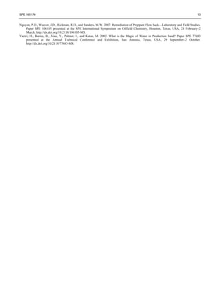
TABLE 1—SUMMARY OF RESERVOIR AND FRACTURING TREATMENT PARAMETERS
Treatment Parameters
Operator A—
Neuquina Basin
Operator B—
GSJ Basin
Operator C—
GSJ Basin
Operator A—
Austral Basin
Number of fracturing
treatments performed
52 105 31 17
Number of fracturing
treatments per well
2 3 to 4 1 to 2 1
Fracture depth (m) 550 to 1800 585 to 2880 730 to 1370 1610 to 2830
BHST (°F) 95 to 165 108 to 235 110 to 140 170 to 245
Fracture gradient (psi/ft)] 0.53 to 1.05 0.50 to 0.89 0.48 to 0.56 0.55 to 1.15
Young’s modulus (psi) 3.5 to 4.5 E+6 0.80 to 1.05 E+6 0.67 to 0.85 E+5 3.5 to 4.5 E+6
Pad volume (%) 33 to 54 12 to 22 36 to 65 27 to 48
Pump rate (bbl/min)
14 to 45 (>75% Fracturing
treatments < 20 bbl/min)
12 to 25 (93% Fracturing
treatments < 20 bbl/min)
12 to 16 (42% Fracturing
treatments < 14 bbl/min)
15 to 28 (60% Fracturing
treatments < 20 bbl/min)
Wellhead pressure (psi) 1,000 to 5,400 1,350 to 5,800 700 to 2,200 2,600 to 6,700
Max proppant
concentration (lbm/gal)
6 to 8 7 to 8 9 to 10 8 to 9
Fracturing fluid Low-temp borate gel (98%)
Mid-temp borate gel
(92%)
Low-temp borate gel
(100%)
Mid-temp borate gel
(89%)
Proppant type White sand (98%)
White sand (80%) and
intermediate-strength
bauxite (20%)
White sand (100%)
Intermediate-strength
bauxite (95%)
Proppant size (mesh)
12/20 (56%) and 16/30
(40%)
12/20 (2%), 16/30
(11%), and 20/40 (67%)
12/20 (100%)
16/30 (18%) and 20/40
(82%)
Post-fracture shut-in
time
4 to 8 hr (90%)
2 to 8 hr (55%) and
Forced closure (20%)
24 hr (100%) 4 to 12 hr (76%)
The main fracturing treatment was commonly preceded by a mini-fracturing treatment. The step-rate tests were only
performed when excess friction pressure was observed. Depending on the preference of the operators in the basin, nearly
80% of the fracturing treatments were performed as a single treatment per well. However, the other 20% were performed
with multistage (two or more) treatments per well on the same day. Operator B in the GSJ basin could perforate a specific
interval and perform a single fracturing treatment for this perforated interval; several fracturing treatments would be
performed per well. In contrast, Operator C in this same basin often grouped several perforated intervals (i.e., three to five
intervals) together in a fracture treatment.
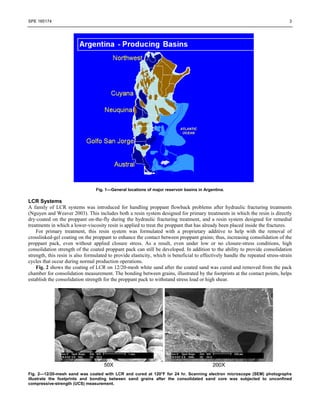
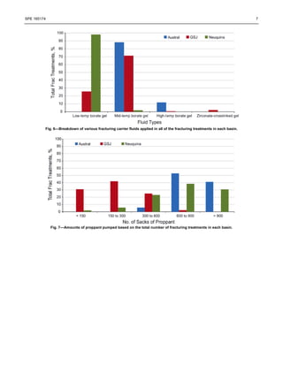
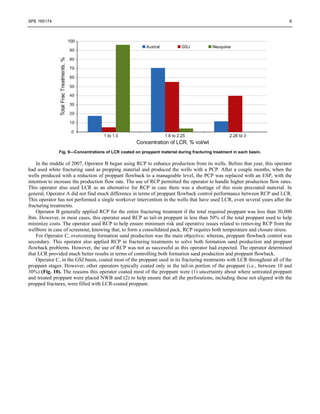
The fracturing fluid was generally pumped down tubing. The average pad size for the wells was between 15 and 65% of
the total fluid volume. Pump rates applied in the fracturing treatments ranged from 12 to 45 bbl/min; however, more than half
of the fracturing treatments were performed with pump rates less than 20 bbl/min. Fig. 8 shows various ranges of pump rates
that have been applied in the basins based on the total number of fracturing treatments.
Fig. 8—Ranges of pump rates applied in the fracturing treatments based on their total number of treatments.
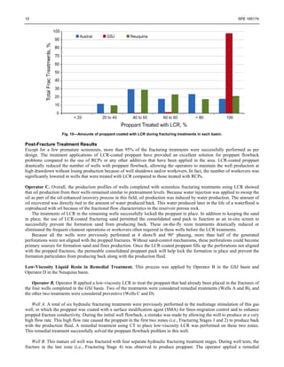
Both RCP and the on-the-fly LCR were used to solve proppant flowback problems. Fig. 9 shows the concentrations of
LCR used for treating the fracturing sand or proppant in each basin.
9. SPE 165174 9
Fig. 9—Concentrations of LCR coated on proppant material during fracturing treatment in each basin.
In the middle of 2007, Operator B began using RCP to enhance production from its wells. Before that year, this operator
had used white fracturing sand as propping material and produced the wells with a PCP. After a couple months, when the
wells produced with a reduction of proppant flowback to a manageable level, the PCP was replaced with an ESP, with the
intention to increase the production flow rate. The use of RCP permitted the operator to handle higher production flow rates.
This operator also used LCR as an alternative for RCP in case there was a shortage of this resin precoated material. In
general, Operator A did not find much difference in terms of proppant flowback control performance between RCP and LCR.
This operator has not performed a single workover intervention in the wells that have used LCR, even several years after the
fracturing treatments.
Operator B generally applied RCP for the entire fracturing treatment if the total required proppant was less than 30,000
lbm. However, in most cases, this operator used RCP as tail-in proppant in less than 50% of the total proppant used to help
minimize costs. The operator used RCP to help ensure minimum risk and operative issues related to removing RCP from the
wellbore in case of screenout, knowing that, to form a consolidated pack, RCP requires both temperature and closure stress.
For Operator C, overcoming formation sand production was the main objective; whereas, proppant flowback control was
secondary. This operator also applied RCP in fracturing treatments to solve both formation sand production and proppant
flowback problems. However, the use of RCP was not as successful as this operator had expected. The operator determined
that LCR provided much better results in terms of controlling both formation sand production and proppant flowback.
Operator C, in the GSJ basin, coated most of the proppant used in its fracturing treatments with LCR throughout all of the
proppant stages. However, other operators typically coated only in the tail-in portion of the proppant (i.e., between 10 and
30%) (Fig. 10). The reasons this operator coated most of the proppant were (1) uncertainty about where untreated proppant
and treated proppant were placed NWB and (2) to help ensure that all the perforations, including those not aligned with the
propped fractures, were filled with LCR-coated proppant.
10. 10 SPE 165174
Fig. 10—Amounts of proppant coated with LCR during fracturing treatments in each basin.
Post-Fracture Treatment Results
Except for a few premature screenouts, more than 95% of the fracturing treatments were successfully performed as per
design. The treatment applications of LCR-coated proppant have provided an excellent solution for proppant flowback
problems compared to the use of RCPs or any other additives that have been applied in the area. LCR-coated proppant
drastically reduced the number of wells with proppant flowback, allowing the operators to maintain the well production at
high drawdown without losing production because of well shutdown and/or workovers. In fact, the number of workovers was
significantly lowered in wells that were treated with LCR compared to those treated with RCPs.
Operator C. Overall, the production profiles of wells completed with screenless fracturing treatments using LCR showed
that oil production from their wells remained similar to pretreatment levels. Because water injection was applied to sweep the
oil as part of the oil-enhanced recovery process in this field, oil production was induced by water production. The amount of
oil recovered was directly tied to the amount of water produced back. This water produced later in the life of a waterflood is
coproduced with oil because of the fractional flow characteristics in the reservoir porous rock.
The treatments of LCR in the remaining wells successfully locked the proppant in place. In addition to keeping the sand
in place, the use of LCR-coated fracturing sand permitted the consolidated sand pack to function as an in-situ screen to
successfully prevent the formation sand from producing back. These on-the-fly resin treatments drastically reduced or
eliminated the frequent cleanout operations or workovers often required in these wells before the LCR treatments.
Because all the wells were previously perforated at 4 shots/ft and 90° phasing, more than half of the generated
perforations were not aligned with the propped fractures. Without sand-control mechanisms, these perforations could become
primary sources for formation sand and fines production. Once the LCR-coated proppant fills up the perforations not aligned
with the propped fractures, the permeable consolidated proppant pack will help lock the formation in place and prevent the
formation particulates from producing back along with the production fluid.
Low-Viscosity Liquid Resin in Remedial Treatment. This process was applied by Operator B in the GSJ basin and
Operator D in the Neuquina basin.
Operator B. Operator B applied a low-viscosity LCR to treat the proppant that had already been placed in the fractures of
the four wells completed in the GSJ basin. Two of the treatments were considered remedial treatments (Wells A and B), and
the other two treatments were considered preventive (Wells C and D).
Well A. A total of six hydraulic fracturing treatments were previously performed in the multistage stimulation of this gas
well, in which the proppant was coated with a surface modification agent (SMA) for fines-migration control and to enhance
propped fracture conductivity. During the initial well flowback, a mistake was made by allowing the well to produce at a very
high flow rate. This high flow rate caused the proppant in the first two zones (i.e., Fracturing Stages 1 and 2) to produce back
with the production fluid. A remedial treatment using CT to place low-viscosity LCR was performed on these two zones.
This remedial treatment successfully solved the proppant flowback problem in this well.
Well B. This mature oil well was fractured with four separate hydraulic fracturing treatment stages. During well tests, the
fracture in the last zone (i.e., Fracturing Stage 4) was observed to produce proppant. The operator applied a remedial
11. SPE 165174 11
treatment process involving CT to place a low-viscosity LCR to address the problem. After the treatment, the operator was
able to test, evaluate, and produce the well without proppant flowing back.
Well C. This is a new oil and gas well in which three separate hydraulic fracturing treatments were performed with 20/40-
mesh white sand to create fractures in the three productive zones. Each fracture in these pay zones was tested and was found
to produce injected fluid, gas, and fracturing sand. In fact, Fracture 1 produced more fracturing sand than the others. The
operator applied remedial treatments for all three fractured zones with a low-viscosity LCR treatment (placed using CT) as a
preventive treatment to help ensure that the fracturing sand stayed in place. After performing the treatment, each zone was
tested again, and no fracturing sand was found to produce back.
Well D. This is a new oil well that had five productive intervals. Five separate hydraulic fracturing treatments were
performed with 20/40-mesh white sand to create fractures in these intervals. During testing, the first two fractures were found
to produce proppant. The operator decided to treat all of these fractured intervals with a low-viscosity LCR using CT as a
preventive measure of proppant flowback control. The well was tested after a curing period of the resin, and then was opened
through a small orifice. When changing the orifice diameter from 8 to 12 mm, a higher drawdown pressure occurred, and the
well produced a small amount of proppant; but, since then, it has produced proppant free.
Operator D. An oil well was fractured in October 2004 through four perforated intervals having a net interval of 66 ft.
The well has a BHT of 180°F and a bottomhole pressure of 3,129 psi at 8,202 ft measured depth (MD). Lightweight ceramic
proppant (US 16/30-mesh) was used during the initial fracturing treatment. Initial oil production for this well was
approximately 40 m3
/day, with water cut of 60 to 98%. The proppant continued to produce back after the fracturing
treatment. Three workovers were required to remove the proppant from the wellbore. Pump efficiency was drastically
reduced, and oil production was decreased to 1 m3
/day.
In December 2005, Operator D applied the remedial treatment method in this well. This involved the use of CT, a
pressure-pulsing tool, and a low-temperature LCR treating fluid system. The treatment fluid included the preflushes (5 gal/ft),
the low-viscosity LCR (2.5 gal/ft), and a post-flush (5 gal/ft). All of these fluids were commingled with nitrogen during
placement because of low reservoir pressure. The liquid injection rate was 1 bbl/min, and the nitrogen gas rate was 800
scf/min. After the remedial treatment, the proppant flowback problem was completely resolved. The oil production rate
steadily returned to 10 m3
/day and then increased, while water cut maintained at around 80%.
Lessons Learned and Recommendations
Perforation Phasing. To minimize the production of sand from the unconsolidated formations, perforations should be shot at
180° phasing (and parallel to the maximum horizontal stress). This part of the well completion helps reduce the number of
perforations that are not aligned with the propped fractures.
Cleaning Out Sand from Perforations and Wellbore. Before performing the fracturing treatment, a thorough cleanup of
perforations and the wellbore was performed to help ensure that no restriction could prevent LCR-coated proppant from
entering and packing all of the perforations, including those not aligned with the propped fractures and/or void spaces that
could exist behind the casing. This simple procedure greatly enhanced the success of the entire treatment.
Fracturing Fluid Compatibility with LCR-Coated Proppant. Quality assurance/quality control (QA/QC) testing of LCR-
coated proppant should be performed with the fracturing fluid that will be used in the fracturing treatment to help ensure the
crosslinking time and break time follow the fracturing treatment design and schedule. This usually involves adjusting the pH
or crosslinker concentration of the fracturing fluid. Because a short crosslinking time is desirable during the tail-in stages of
LCR-coated proppant to enhance grain-to-grain contact between resin-treated proppant grains, lower crosslinker
concentrations and higher breaker concentrations are applied to achieve complete breaking of the crosslinked gel.
Coating Proppant throughout All Stages. Because of the relative length of the perforated interval, the proppant involved in
these treatments was coated throughout all proppant stages. Evidence indicates that, even with a single, short-perforated
interval, the first proppant injected into the fractures can also be the first proppant produced back (Al-Ghurairi et al. 2006).
Early Screenout. It was the intention of the operator to prevent screenout from occurring, especially during coating of LCR
with proppant during the tail-in stage. However, if the screenout occurred during the LCR-treating stage, forced closure was
immediately applied to prevent coated proppant from being cured and forming a consolidated pack inside the wellbore.
Cleaning out or reaming out of the consolidated pack inside the wellbore often required the use of a CT unit or workover rig,
which required additional time and added complexity to the operation.
The resin-coating process can raise some concerns should premature screenouts occur during the fracturing treatment and
the proppant slurry settles inside the wellbore. In this case, the well is flowed back as soon as possible so that tubing will not
be necessary to clean out the wellbore. However, if the screenout occurs toward the end of the treatment, it is a desirable
12. 12 SPE 165174
feature that helps ensure complete coverage of all perforations. When allowed to remain in the wellbore to semicure, the
LCR-coated proppant pack can be cleaned out with tubing, preferably coupled with a drill bit or notched collar.
Forced Closure. A forced-closure method was applied to some of the fracturing treatments. Soon after the displacement
stage was performed and after the treating iron was disassembled from the wellhead, the fracturing fluid was allowed to flow
back. In most cases, the crosslinked fracturing fluid had not been completely broken. However, the principle of the forced-
closure method is to enhance the closure of open fractures while the proppant is still being suspended in the fracturing fluid
such that the fracture closure helps lock the proppant in place before it settles to the bottom of the fractures. This locking
mechanism helps keep the fractures opened or “propped” instead of completely being closed, as in the case of proppant
settled to the lower part of the fracture. Early flowback might help increase BHST to speed up the cure kinetic of coated
proppant. In addition, the early flowback of fracturing fluid during forced-closure enhances the removal of gel residues,
which are often thought to contribute to the conductivity reduction or permeability damage of proppant if allowed to remain
too long inside the fracture.
To minimize the amount of proppant producing back during forced closure, the concentration of breaker is increased by
50 to 100% of the normal amount during the tail-in stage. This increase in breaker concentration promotes the breakdown of
the crosslinked polymer fluid to enhance the grain-to-grain contact of the LCR-coated proppant and minimize the drag force
during flowback of forced closure, especially with crosslinked fluid. The LCR-coated proppant grains are tacky in aqueous-
based fluid; thus, their grain-to-grain contacts should help minimize their movement and flowback with the fracturing fluid,
even though the curing of the LCR on the proppant has not been well-established.
Coating Proppant with Low Resin Concentrations. In terms of resin concentration, a LCR concentration of 1 to 2%
(vol/wt) was often applied to coat the proppant, compared to a typical concentration of 3%, which was often required in other
areas. Depending on the number of fractures and their interval lengths, concentrations of LCR in the range of 2 to 3% should
be applied to attain high consolidation strength for the treated proppant that is essentially located NWB, allowing it to handle
high shear exerted on the proppant during well production.
Shut-in Time for Curing. The well should be shut in after the fracturing treatment for at least 8 hr if the BHST of the well is
175°F or higher. A longer shut-in time is required if the BHST is less than 175°F. Insufficient shut-in time does not allow the
resin-treated proppant pack to obtain sufficient consolidation strength to handle high production flow rates, especially for
wells with a limited number of perforations.
An aggressive breaker schedule is recommended. The gel should be broken as quickly as possible to allow the proppant
grains to obtain grain-to-grain contact before the resin hardens. If the gel is not broken before the resin hardens, the
compressive strength of the pack will be very low. A forced-closure type breaker schedule or a ramped breaker schedule
should be used. A general flowback recommendation is to begin flowback after the shut-in time at less than 1 bbl/min for the
first few hours and then ramp up to the desired flow rate. However, well/reservoir conditions for each well should be
reviewed to determine an appropriate flowback rate.
Conclusions
• With careful planning, liquid resin systems can be efficiently coated on the proppant during hydraulic fracturing
treatments, or applied as part of remedial consolidating treatments, to transform the proppant placed in the fractures
into consolidated, permeable packs for controlling proppant flowback.
• Proper coating and curing of liquid resin onto proppant allows the consolidated proppant to handle the high
drawdown and the effects of stress-strain cycles during well shut-in and production.
• Application of liquid resins provides an effective method for controlling flowback of proppant and formation sand to
maintain well production without disruptions caused by solids production.
Acknowledgments
The authors thank Halliburton for permission to publish this paper.
References
Al-Ghurairi, F., Solares, R., Bartko, K., and Sierra, L. 2006. Results from a Field Trial Using New Additives for Fracture Conductivity
Enhancement in a High-Gas Screenless Completion in the Jauf Reservoir, Saudi Arabia. Paper SPE 98088 presented at the SPE
International Symposium and Exhibition on Formation Damage Control, Lafayette, Louisiana, USA, 15–17 February.
http://dx.doi.org/10.2118/98088-MS.
Nguyen, P.D. and Weaver, J.D. 2003. Controlling Proppant Flowback in High-Temperature, High-Production Wells. Paper SPE 82215
presented at the SPE European Formation Damage Conference, The Hague, The Netherlands, 13–14 May.
http://dx.doi.org/10.2118/82215-MS.
Nguyen, P.D., Stegent, N.A., and Ingram, S.R. 2006. Remediation of Production Loss Due to Proppant Flowback in Existing Wellbores.
Paper SPE 102629 presented at the Annual Technical Conference and Exhibition, San Antonio, Texas, USA, 24–27 September.
http://dx.doi.org/10.2118/102629-MS.
13. SPE 165174 13
Nguyen, P.D., Weaver, J.D., Rickman, R.D., and Sanders, M.W. 2007. Remediation of Proppant Flow back—Laboratory and Field Studies.
Paper SPE 106105 presented at the SPE International Symposium on Oilfield Chemistry, Houston, Texas, USA, 28 February–2
March. http://dx.doi.org/10.2118/106105-MS.
Vaziri, H., Barree, B., Xiao, Y., Palmer, I., and Kutas, M. 2002. What is the Magic of Water in Production Sand? Paper SPE 77683
presented at the Annual Technical Conference and Exhibition, San Antonio, Texas, USA, 29 September–2 October.
http://dx.doi.org/10.2118/77683-MS.