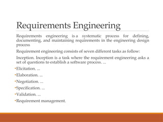
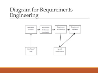
Understanding Requirements
PRESENTED BY
DR.S.VIJAYASANKARI
DEPT OF MCA,
E.M.G YADAVA WOMEN’S COLLEGE,
MADURAI
Requirements Engineering
Requirements engineering is a systematic process for defining,
documenting, and maintaining requirements in the engineering design
process
Requirement engineering consists of seven different tasks as follow:
Inception. Inception is a task where the requirement engineering asks a
set of questions to establish a software process. ...
•Elicitation. ...
•Elaboration. ...
•Negotiation. ...
•Specification. ...
•Validation. ...
•Requirement management.
Diagram for Requirements
Engineering
Requirements Engineering
Inception is a task where the requirement engineering
asks a set of questions to establish a software process.
In this task, it understands the problem and evaluates
with the proper solution. It collaborates with the
relationship between the customer and the developer.
Inception—ask a set of questions that establish …
◦ basic understanding of the problem
◦ the people who want a solution
◦ the nature of the solution that is desired, and
◦ the effectiveness of preliminary communication and
collaboration between the customer and the developer
Inception
Identify stakeholders
◦ “who else do you think I should talk to?”
Recognize multiple points of view
Work toward collaboration
The first questions
◦ Who is behind the request for this work?
◦ Who will use the solution?
◦ What will be the economic benefit of a successful
solution
◦ Is there another source for the solution that you need?
Elicitation
Elicitation—elicit requirements from all stakeholders
Elicitation in requirements engineering is the process
of gathering and discovering the requirements of a
system from users, customers, and other
stakeholders.
In requirements engineering, requirements
elicitation is the practice of researching and
discovering the requirements of a system from users,
customers, and other stakeholders.
Eliciting Requirements
•meetings are conducted and attended by both software engineers
and customers
•rules for preparation and participation are established
•an agenda is suggested
•a "facilitator" (can be a customer, a developer, or an outsider)
controls the meeting
•a "definition mechanism" (can be work sheets, flip charts, or wall
stickers or an electronic bulletin board, chat room or virtual forum)
is used
•the goal is
• to identify the problem
• propose elements of the solution
• negotiate different approaches, and
• specify a preliminary set of solution requirements
Elaboration and Negotiation
Elaboration—create an analysis model that identifies data,
function and behavioral requirements
In this task, the information taken from user during inception and
elaboration and are expanded and refined in elaboration. Its main
task is developing pure model of software using functions,
feature and constraints of a software.
Negotiation—agree on a deliverable system that is realistic for
developers and customers
Requirement negotiation is a part of the requirements engineering
(RE) process, which is used in software development life-cycle
models. It involves discussing and resolving conflicts between
stakeholders to reach a compromise that satisfies everyone. The
goal is to create a set of requirements that meet predetermined
quality criteria, such as correctness and agreement.
Specification
In requirement engineering, a specification is a document that
outlines the requirements for a product or process. It's a critical part
of the requirements engineering process, and is usually created after
requirements capture and analysis.
A requirement specification, which is a set of documented
requirements to be satisfied by a material, design, product, or service.
Specification—can be any one (or more) of the following:
◦ A written document
◦ A set of models
◦ A formal mathematical
◦ A collection of user scenarios (use-cases)
◦ A prototype
Validation
In requirement engineering, validation is the process of confirming that the
documented requirements match the needs of the stakeholders. It's a phase in the
software development life cycle that ensures the requirements are suitable for the
product.
Validation—a review mechanism that looks for
◦ errors in content or interpretation
◦ areas where clarification may be required
◦ missing information
◦ inconsistencies (a major problem when large products or systems are engineered)
◦ conflicting or unrealistic (unachievable) requirements.
◦ Requirements management conflicting or unrealistic (unachievable) requirements.
◦ The primary goal of systems engineering (SE) is to develop a solution that meets the
needs and requirements of stakeholders. Validation is the process by which
engineers ensure that the system will meet these needs and requirements.
Requirements management
Requirements management is the process of gathering, analyzing,
verifying, and validating the needs and requirements for the given
product or system being developed..
Requirements management process
Collect initial requirements from stakeholders.
Analyze requirements.
Define and record requirements.
Prioritize requirements.
Agree on and approve requirements.
Trace requirements to work items.
Query stakeholders after implementation on needed changes to
requirements.
Building the Analysis Model
Elements of the analysis model
◦ Scenario-based elements
◦ Functional—processing narratives for software functions
◦ Use-case—descriptions of the interaction between an
“actor” and the system
◦ Class-based elements
◦ Implied by scenarios
◦ Behavioral elements
◦ State diagram
◦ Flow-oriented elements
◦ Data flow diagram
Scenario-based elements
Scenarios are brief narratives of expected or anticipated use of a system
from both development and end-user viewpoints.
Scenario modeling typically considers three primary types of
scenarios: worst-case, best-case and average scenarios. The worst-case
scenario explores the outcomes under the most adverse conditions,
helping businesses prepare for the toughest challenges.
A scenario analysis generally considers at least three types of
scenarios:
Base-case scenario: A baseline scenario based on current, commonly
accepted assumptions.
Worst-case scenario: The most negative set of assumptions.
Best-case scenario: The ideal projected scenario to achieve goals and
objectives.
Class – based elements
Class-based elements: Each usage scenario implies a
set of “objects” that are manipulated as an actor
interacts with the system. These objects are
categorized into classes- a collection of things that
have similar attributes and common behaviors.
Class-based elements : A collection of things that
have similar attributes and common behaviors i.e.,
objects are categorized into classes..
The elements of a class-based model include classes
and objects, attributes, operations, class
responsibility- collaborator (CRC) models,
collaboration diagrams, and packages
Diagram for Class-based
Elements
Behavioral elements
Behavioral elements depict how external events change the state
of the system
Behavior elements are the strategic elements course of action and
capability, and behavioral elements, which can be subdivided
into internal behavior elements, external behavior elements (also
called services), and events. or the classes that reside within it.
Two types of behavioral models
There are two types of behavioral models that are used to
describe the system behavior, one is data processing model and
another is state machine models. Data processing models are also
known as DFD (Data Flow Diagram) which is used to show how
data is processed as it moves through the system.
Flow-oriented elements
Flow-oriented elements: Information is transformed as it flows through a
computer-based system. The system accepts input in a variety of forms; applies
functions to transform it; and produces output in a variety of forms.
Flow-oriented modeling represents how data objects are transformed as they
move through a system. A data flow diagram (DFD) is the diagrammatic form
used to depict this approach. DFDs show the flow of data through processes and
external entities of a system using symbols like circles and arrows.
Data Flow Diagram Symbols
External Entity. External entities — which are also known as terminators,
sources, sinks, or actors — are outside systems that send or receive data to and
from the diagrammed system. ...
Process. ...
Data Store. ...
Data Flow.
Diagram for Flow-oriented
Elements
Diagram for Flow-oriented
Elements
Use-Cases
Use cases in software engineering are a user-centric way to
represent how a user interacts with a product or system. They can
be written as documents or created visually using a use case
model. Use cases help with a variety of tasks, including:
A use case defines a goal-oriented set of interactions between
external actors and the system under consideration. A primary
actor triggers the system behavior in order to achieve a certain
goal. A secondary actor interacts with the system but does not
trigger the use case
A collection of user scenarios that describe the thread of usage of
a system
Each scenario is described from the point-of-view of an “actor”—
a person or device that interacts with the software in some way
Use Cases
Each scenario answers the following questions:
◦ Who is the primary actor, the secondary actor (s)?
◦ What are the actor’s goals?
◦ What preconditions should exist before the story begins?
◦ What main tasks or functions are performed by the actor?
◦ What extensions might be considered as the story is described?
◦ What variations in the actor’s interaction are possible?
◦ What system information will the actor acquire, produce, or change?
◦ Will the actor have to inform the system about changes in the external
environment?
◦ What information does the actor desire from the system?
◦ Does the actor wish to be informed about unexpected changes?
Thank You

Software Engineering- Understanding Requirements

  • 1.
    Understanding Requirements PRESENTED BY DR.S.VIJAYASANKARI DEPTOF MCA, E.M.G YADAVA WOMEN’S COLLEGE, MADURAI
  • 2.
    Requirements Engineering Requirements engineeringis a systematic process for defining, documenting, and maintaining requirements in the engineering design process Requirement engineering consists of seven different tasks as follow: Inception. Inception is a task where the requirement engineering asks a set of questions to establish a software process. ... •Elicitation. ... •Elaboration. ... •Negotiation. ... •Specification. ... •Validation. ... •Requirement management.
  • 3.
  • 4.
    Requirements Engineering Inception isa task where the requirement engineering asks a set of questions to establish a software process. In this task, it understands the problem and evaluates with the proper solution. It collaborates with the relationship between the customer and the developer. Inception—ask a set of questions that establish … ◦ basic understanding of the problem ◦ the people who want a solution ◦ the nature of the solution that is desired, and ◦ the effectiveness of preliminary communication and collaboration between the customer and the developer
  • 5.
    Inception Identify stakeholders ◦ “whoelse do you think I should talk to?” Recognize multiple points of view Work toward collaboration The first questions ◦ Who is behind the request for this work? ◦ Who will use the solution? ◦ What will be the economic benefit of a successful solution ◦ Is there another source for the solution that you need?
  • 6.
    Elicitation Elicitation—elicit requirements fromall stakeholders Elicitation in requirements engineering is the process of gathering and discovering the requirements of a system from users, customers, and other stakeholders. In requirements engineering, requirements elicitation is the practice of researching and discovering the requirements of a system from users, customers, and other stakeholders.
  • 7.
    Eliciting Requirements •meetings areconducted and attended by both software engineers and customers •rules for preparation and participation are established •an agenda is suggested •a "facilitator" (can be a customer, a developer, or an outsider) controls the meeting •a "definition mechanism" (can be work sheets, flip charts, or wall stickers or an electronic bulletin board, chat room or virtual forum) is used •the goal is • to identify the problem • propose elements of the solution • negotiate different approaches, and • specify a preliminary set of solution requirements
  • 8.
    Elaboration and Negotiation Elaboration—createan analysis model that identifies data, function and behavioral requirements In this task, the information taken from user during inception and elaboration and are expanded and refined in elaboration. Its main task is developing pure model of software using functions, feature and constraints of a software. Negotiation—agree on a deliverable system that is realistic for developers and customers Requirement negotiation is a part of the requirements engineering (RE) process, which is used in software development life-cycle models. It involves discussing and resolving conflicts between stakeholders to reach a compromise that satisfies everyone. The goal is to create a set of requirements that meet predetermined quality criteria, such as correctness and agreement.
  • 9.
    Specification In requirement engineering,a specification is a document that outlines the requirements for a product or process. It's a critical part of the requirements engineering process, and is usually created after requirements capture and analysis. A requirement specification, which is a set of documented requirements to be satisfied by a material, design, product, or service. Specification—can be any one (or more) of the following: ◦ A written document ◦ A set of models ◦ A formal mathematical ◦ A collection of user scenarios (use-cases) ◦ A prototype
  • 10.
    Validation In requirement engineering,validation is the process of confirming that the documented requirements match the needs of the stakeholders. It's a phase in the software development life cycle that ensures the requirements are suitable for the product. Validation—a review mechanism that looks for ◦ errors in content or interpretation ◦ areas where clarification may be required ◦ missing information ◦ inconsistencies (a major problem when large products or systems are engineered) ◦ conflicting or unrealistic (unachievable) requirements. ◦ Requirements management conflicting or unrealistic (unachievable) requirements. ◦ The primary goal of systems engineering (SE) is to develop a solution that meets the needs and requirements of stakeholders. Validation is the process by which engineers ensure that the system will meet these needs and requirements. Requirements management
  • 11.
    Requirements management Requirements managementis the process of gathering, analyzing, verifying, and validating the needs and requirements for the given product or system being developed.. Requirements management process Collect initial requirements from stakeholders. Analyze requirements. Define and record requirements. Prioritize requirements. Agree on and approve requirements. Trace requirements to work items. Query stakeholders after implementation on needed changes to requirements.
  • 12.
    Building the AnalysisModel Elements of the analysis model ◦ Scenario-based elements ◦ Functional—processing narratives for software functions ◦ Use-case—descriptions of the interaction between an “actor” and the system ◦ Class-based elements ◦ Implied by scenarios ◦ Behavioral elements ◦ State diagram ◦ Flow-oriented elements ◦ Data flow diagram
  • 13.
    Scenario-based elements Scenarios arebrief narratives of expected or anticipated use of a system from both development and end-user viewpoints. Scenario modeling typically considers three primary types of scenarios: worst-case, best-case and average scenarios. The worst-case scenario explores the outcomes under the most adverse conditions, helping businesses prepare for the toughest challenges. A scenario analysis generally considers at least three types of scenarios: Base-case scenario: A baseline scenario based on current, commonly accepted assumptions. Worst-case scenario: The most negative set of assumptions. Best-case scenario: The ideal projected scenario to achieve goals and objectives.
  • 14.
    Class – basedelements Class-based elements: Each usage scenario implies a set of “objects” that are manipulated as an actor interacts with the system. These objects are categorized into classes- a collection of things that have similar attributes and common behaviors. Class-based elements : A collection of things that have similar attributes and common behaviors i.e., objects are categorized into classes.. The elements of a class-based model include classes and objects, attributes, operations, class responsibility- collaborator (CRC) models, collaboration diagrams, and packages
  • 15.
  • 16.
    Behavioral elements Behavioral elementsdepict how external events change the state of the system Behavior elements are the strategic elements course of action and capability, and behavioral elements, which can be subdivided into internal behavior elements, external behavior elements (also called services), and events. or the classes that reside within it. Two types of behavioral models There are two types of behavioral models that are used to describe the system behavior, one is data processing model and another is state machine models. Data processing models are also known as DFD (Data Flow Diagram) which is used to show how data is processed as it moves through the system.
  • 17.
    Flow-oriented elements Flow-oriented elements:Information is transformed as it flows through a computer-based system. The system accepts input in a variety of forms; applies functions to transform it; and produces output in a variety of forms. Flow-oriented modeling represents how data objects are transformed as they move through a system. A data flow diagram (DFD) is the diagrammatic form used to depict this approach. DFDs show the flow of data through processes and external entities of a system using symbols like circles and arrows. Data Flow Diagram Symbols External Entity. External entities — which are also known as terminators, sources, sinks, or actors — are outside systems that send or receive data to and from the diagrammed system. ... Process. ... Data Store. ... Data Flow.
  • 18.
  • 19.
  • 20.
    Use-Cases Use cases insoftware engineering are a user-centric way to represent how a user interacts with a product or system. They can be written as documents or created visually using a use case model. Use cases help with a variety of tasks, including: A use case defines a goal-oriented set of interactions between external actors and the system under consideration. A primary actor triggers the system behavior in order to achieve a certain goal. A secondary actor interacts with the system but does not trigger the use case A collection of user scenarios that describe the thread of usage of a system Each scenario is described from the point-of-view of an “actor”— a person or device that interacts with the software in some way
  • 21.
    Use Cases Each scenarioanswers the following questions: ◦ Who is the primary actor, the secondary actor (s)? ◦ What are the actor’s goals? ◦ What preconditions should exist before the story begins? ◦ What main tasks or functions are performed by the actor? ◦ What extensions might be considered as the story is described? ◦ What variations in the actor’s interaction are possible? ◦ What system information will the actor acquire, produce, or change? ◦ Will the actor have to inform the system about changes in the external environment? ◦ What information does the actor desire from the system? ◦ Does the actor wish to be informed about unexpected changes?
  • 22.