UNIT III : Software Design
Software Design
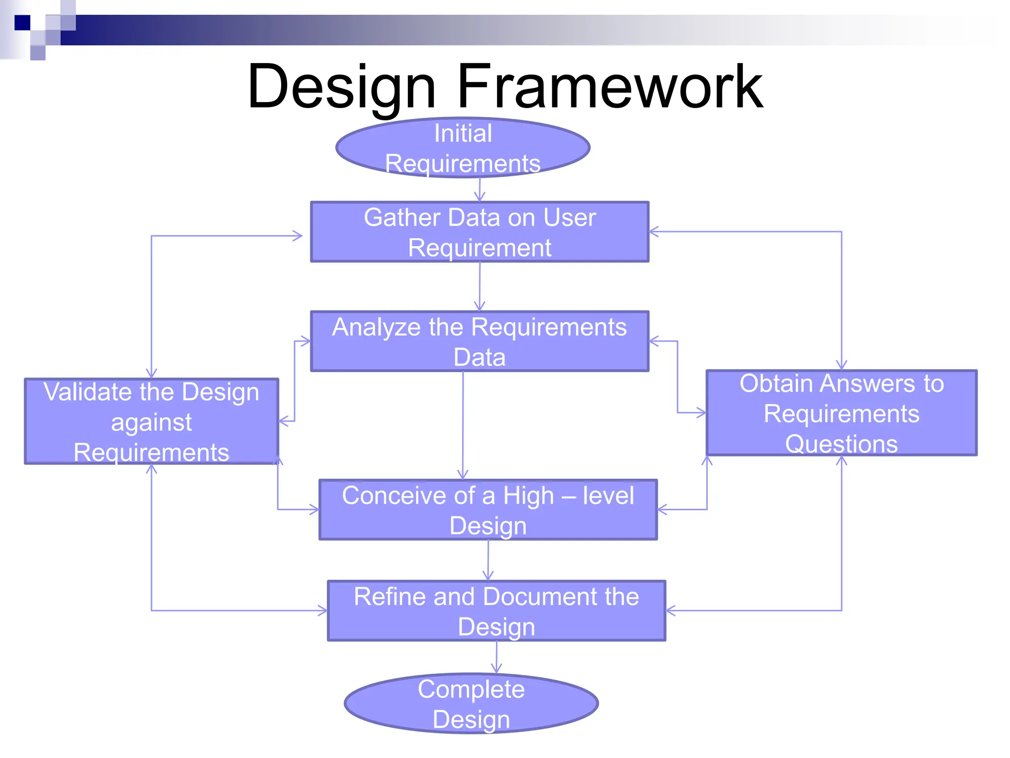
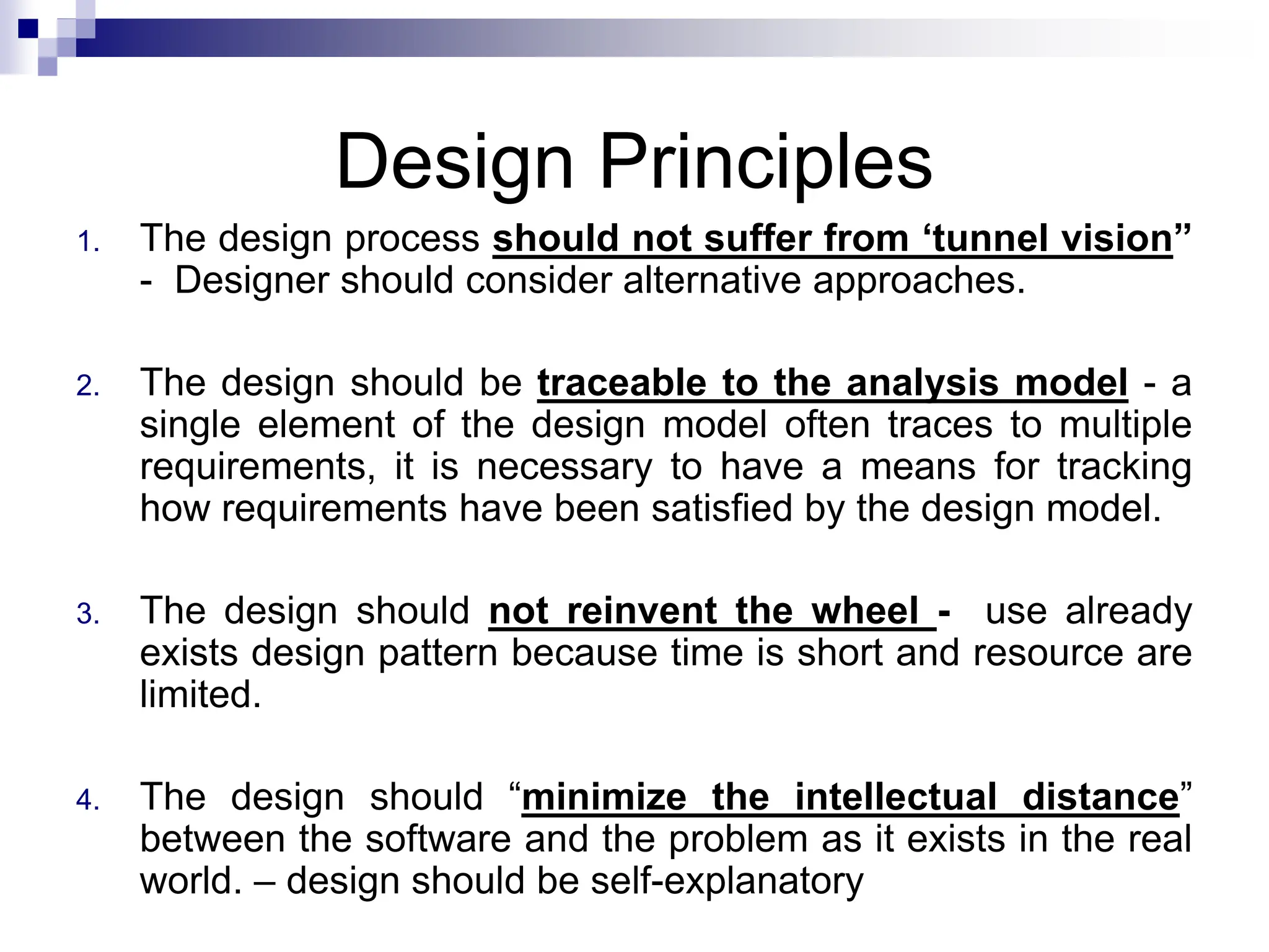
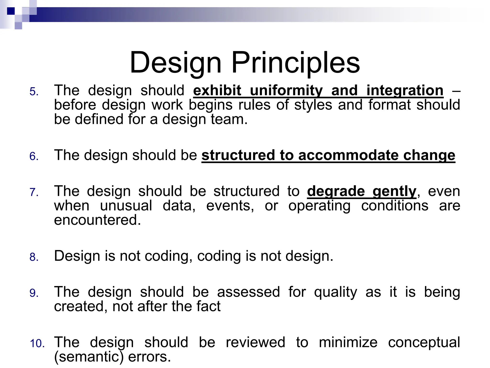
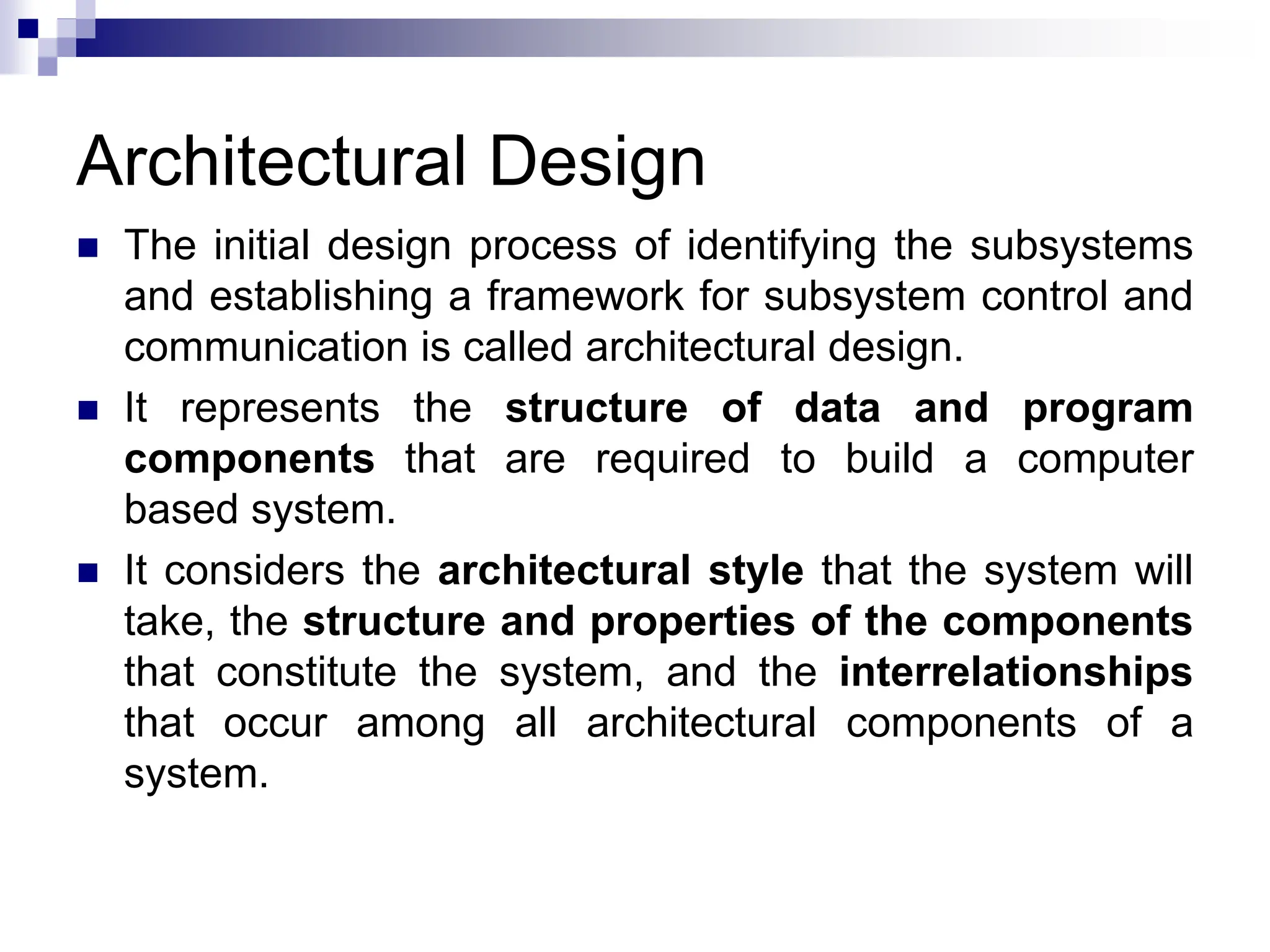
 Software design is an iterative process during which the
software requirements specified in SRS are analyzed and
converted into description of the internal structure and
organization of the system.
 The document thus produced is called the software design
specification document and serves as the basis for
construction of the software.
 Design Process for software system has two levels:
1. Software Architectural Design or High Level Design :
In this system is decomposed and organized into high level
components or modules and the interfaces between these
components are also described.
2. Software Implementation or Detailed Design : In it,
each component is described in sufficient detail so that it
can be easily coded by the programmers.
Goal of Design Process
 The design must implement all of the explicit
requirements contained in the analysis model, and it
must accommodate all of the implicit requirements
desired by the customer.
 The design must be a readable, understandable
guide for those who generate code and for those who
test and subsequently support the software.
 The design should provide a complete picture of the
software, addressing the data, functional, and
behavioral domains from an implementation
perspective.
Characteristics of good design
1. A design should exhibit an architecture that is been created using
recognizable architectural styles or patterns.
2. A design should be modular; that is, the software should be
logically partitioned into elements or subsystems
3. A design should contain distinct representations of data,
architecture, interfaces, and components.
4. A design should lead to data structures that are appropriate for
the classes to be implemented and are drawn from recognizable
data patterns.
5. A design should lead to components that exhibit independent
functional characteristics
Characteristics of good design
6. A design should lead to interfaces that reduce the
complexity of connections between components and
with the external environment.
7. A design should be derived using a repeatable
method that is driven by information obtained during
software requirements analysis.
8. A design should be represented using a notation that
effectively communicates its meaning.
Design Framework
 Design Framework starts with the initial
requirements and ends up with the final
design
 Data is gathered on user requirements
and analyzed accordingly.
 Design is refined in every cycle and finally
it is documented to produce software
design document.
Design Framework
Initial
Requirements
Complete
Design
Gather Data on User
Requirement
Analyze the Requirements
Data
Conceive of a High – level
Design
Refine and Document the
Design
Obtain Answers to
Requirements
Questions
Validate the Design
against
Requirements
Design Principles
1. The design process should not suffer from ‘tunnel vision”
- Designer should consider alternative approaches.
2. The design should be traceable to the analysis model - a
single element of the design model often traces to multiple
requirements, it is necessary to have a means for tracking
how requirements have been satisfied by the design model.
3. The design should not reinvent the wheel - use already
exists design pattern because time is short and resource are
limited.
4. The design should “minimize the intellectual distance”
between the software and the problem as it exists in the real
world. – design should be self-explanatory
Design Principles
5. The design should exhibit uniformity and integration –
before design work begins rules of styles and format should
be defined for a design team.
6. The design should be structured to accommodate change
7. The design should be structured to degrade gently, even
when unusual data, events, or operating conditions are
encountered.
8. Design is not coding, coding is not design.
9. The design should be assessed for quality as it is being
created, not after the fact
10. The design should be reviewed to minimize conceptual
(semantic) errors.
Architectural Design
 The initial design process of identifying the subsystems
and establishing a framework for subsystem control and
communication is called architectural design.
 It represents the structure of data and program
components that are required to build a computer
based system.
 It considers the architectural style that the system will
take, the structure and properties of the components
that constitute the system, and the interrelationships
that occur among all architectural components of a
system.
Architectural Design
 Alternate architectural styles of designing a system are:
1. Data Centric Architecture : involves the use of central database
operations of inserting, updating it in the form of a table.
2. Data Flow Architecture : It is applied when input data takes the
form of output after passing through various phases of
transformations.
3. Object – Oriented Architecture : moves around the classes and
objects of the system
4. Layered Architecture : Defines a number of layers and each layer
performs tasks.
Objectives of Architectural Design
1. Develop a model of software architecture, which gives a overall
organization of program module in the software product. Software
architecture encompasses two aspects of the data and hierarchical
structure of the software components.
 Let us see how a single problem can be translated to a collection of
solution domains
 Architectural design defines organization of program components.
It does not provide the details and implementation of components.
S1 S5
S2
S6
S4
S3
S6
S4
S3
S5
S2
S1
Problem
Objectives of Architectural Design
2. Its objective is also to control relationship between modules. One
module may control another module or maybe controlled by another
module. These characteristics are defined by fan – in and fan – out of
a particular module. The organization of module can be represented
through a tree like structure.
i. Fan – in : The number of components, which controls a said
component ie. The number of incoming edges to a component
ii. Fan – out : The number of components that are controlled by the
module ie. The number of outgoing edges.
iii. Depth : The number of level of component in the structure
iv. Width : The number components across the horizontal section .
Fan – out is 3 Fan – out is 2
S2
S5
S1
S5
S2
S1
S0
Low Level Design
 Modularization
 A system is considered modular if it consists of discrete
components so that each component can be
implemented separately and a change to one component
has minimal impact on other components.
 Properties of modular system are :
1. Each function has a single well defined purpose.
2. Each function manipulates no more than one major data structure.
3. Functions share global data selectively.
4. Functions that manipulate instances of abstract data types are
encapsulated with the data structure being manipulated.
Low Level Design
 Advantages of modular system are :
1. Easier to understand and explain.
2. Easier to document.
3. Programming individual modules is easier.
4. Testing and debugging individual modules is easier.
5. Bugs are easier to isolate and understand, and they can
be fixed without fear of introducing problems outside the
module.
Low Level Design
 Modularity
 Software is divided into separately named and
addressable components, called modules, which are
integrated to satisfy problem requirement.
 Modularity is the single attribute of software that allows a
program to be intellectually manageable
 It leads to a “divide and conquer” strategy. – it is easier
to solve a complex problem when you break into a
manageable pieces.
Low Level Design
 Modularity
 Modules created during program modularization are:
1. Process Support Modules : In it all the functions and
data items that are required to support a particular
business process are grouped together.
2. Data Abstraction : These are abstract types that are
created by associating data with processing
components.
3. Functional Modules : In it all the function that carried
out similar or closely related tasks is grouped together.
4. Hardware Modules : In it all the functions, which
controls on particular hardware are grouped together.
Modularity and software cost
Above Figure states that effort (cost) to develop an individual
software module does decrease if total number of modules
increase. However as the no. of modules grows, the effort
(cost) associated with integrating the modules also grows.
Structured Design
 The aim of structured design is to transform the results
of the structured analysis (i.e. a DFD representation) into
a structure chart.
 A structure chart represents the software architecture,
i.e. the various modules making up the system, the
dependency (which module calls which other modules),
and the parameters that are passed among the different
modules.
 Hence, the structure chart representation can be easily
implemented using some programming language.
 The procedural aspects (e.g. how a particular
functionality is achieved) are not represented in structure
chart.
Basic Element of Structure Chart –
“Module”
 A module is defined as a collection of
program statements with four attributes:
 input and output - what the module gets from its
invoker and what the invoker receives from the
module
 function - what it does to its input to produce its
output
 mechanics - the code or logic by which it carries out
its function
 internal data - its own private workspace, data to
which it alone refers
Basic building Blocks of Structure Charts
1. Rectangular boxes: Represents a module.
2. Module invocation arrows: Control is passed from one
module to another module in the direction of the
connecting arrow.
3. Data flow arrows: Arrows are annotated with data
name; named data passes from one module to another
module in the direction of the arrow.
4. Library modules: When a module is invoked by many
other modules, it is made into a library module.
Basic building Blocks of Structure Charts
5. Selection: One module out of several modules
connected with diamond symbol are invoked depending
upon the condition satisfied, which is written in the
diamond symbol.
6. Repetition: Represented by a loop around the control
flow arrow. It denotes that the respective modules are
invoked repeatedly.
Connections between modules
 A connection indicates that one module calls another
module. The components are read from top to bottom,
left to right. There is one and only one module at the top
called the root.
A
B
Calling Module
Called Module
Get
Customer
Details
Find
Customer
Name
Showing Data and Information
 The module uses data and flags
 Need to show the movement of data and the
movement of information about data (flags)
 Flag is used as a control signal
Get
Customer
Details
Find
Customer
Name
Customer
Account
Number
Customer
Name
Account
Number is
OK
Flag going from caller to called
Flag going from called to caller
Data going from caller to called
Data going from called to caller
Difference between Data and
Flags
 Data is processed, flags are not
 A flag is typically set and tested
 Data relates to the problem
 Flags communicate information about the
data
Iteration and Decision on a
Structure Chart
Issue pay
cheques
for all
employees
Print Pay
Cheque
Calculate Pay
for Salaried
Worker
Calculate Pay
for Casual
Worker
Get Employee
Pay Record
Symbol for showing
decisions Symbol for showing
iteration
Example Structure Chart
SUMMARIZE
PAYMENTS FOR
ALL
CUSTOMERS
PUT
CUSTOMER
TOTAL
PUT FINAL
TOTAL
GET VALID
CUSTOMER
RECORD
EDIT FIELD
GET TOTAL
PAYMENT FOR
ONE
CUSTOMER
READ
PRINT
Total for One
Customer
Total for One
Customer
Total for All
Customers
Valid Customer Record
Customer Record
Field
Field Valid
Valid
Entry
done
Record
is Valid
Customer
Total Line
Final Total
Line
Flow Chart v/s Structure Chart
Flow chart is a convenient technique to represent
the flow of control in a program. A structure chart
differs from a flow chart in three principal ways:
1. It is usually difficult to identify the different
modules of the software from its flow chart
representation.
2. Data interchange among different modules is
not represented in a flow chart.
3. Sequential ordering of tasks inherent in a flow
chart is suppressed in a structure chart.
Pseudocode
•It is a combination of algorithm written in
simple language and programming language
statements.
•Pseudo-code notation can be used in both the
preliminary and detailed design phases.
•Using Pseudo-code, the designer describes system
characteristics structured by keywords such as IF –
THEN – ELSE, While – Do and End.
Pseudocode Example
Find smallest number among three variables
1. Read values of a, b and c
2. If (a<b)
{
if (a<c)
print “ a is smallest “
Else
print “ c is smallest “
}
Else if(b<c)
print “ b is smallest “
Else
print “ c is smallest “
Pseudocode Advantages
1. Converting a pseudocode to a programming
language is much easier as compared to converting to
flowchart or decision table.
2. As compared to flowchart, it is easier to modify the
pseudocode of program logic whenever program
modifications are necessary.
3. Writing of pseudocode involves much less time and
effort than equivalent flowchart.
4. Pseudocode is easier to write than writing a
program in a programming language because it has
only a few rules to follow.
Pseudocode Disadvantages
1. In case of Pseudocode, a graphic representation of
program logic is not available as in flowcharts.
2. No standard rules to follow in using Pseudocode.
Different programmers use their own style of writing
pseudocode hence communication problems occur due to
lack of standardization.
3. For a beginner, it is more difficult to follow the logic or
write the Pseudocode, as compared to flowcharting.
EFFECTIVE MODULAR DESIGN
 Effective modular design consist of two
things:
Cohesion
Coupling
Cohesion
 Cohesion is a natural extension of the information hiding
concept.
 It is the extent to which all instructions in a module
relate to a single function.
 Cohesion in modules should be maximized.
 A cohesive module performs a single task within a
software procedure, requiring little interaction with
procedures being performed in other parts of a program
 We always strive for high cohesion, although the mid-
range of the spectrum is often acceptable.
 A strongly cohesive module implements functionality that
is related to one feature of the solution and requires little
or no interaction with other modules.
Types of cohesion
1. Functional Cohesion : All activities in a module are functionally
related or they are performing a similar function. It is the best
cohesion as the module perform a single specific function.
2. Sequential Cohesion : Modules are divided into a series of
activities such that the output of one module becomes the input to
the next module and the chain continues.
3. Communicational Cohesion : All the functions of the module refer
to or update the same data structure. It has clearly defined
boundaries, inputs and outputs but it suffers from one major
weakness, ie., if the common area is changed then all modules
have to be checked out again.
4. Procedural Cohesion : In it activities share the same procedural
implementation. If procedural cohesion is done on a module of a
system, it will be in a situation where a number of modules share
some common procedures and the common procedure is being
automated. Eg. The algorithm for decoding a message
Types of cohesion
5. Temporal Cohesion : When a module contains functions that are
related by the fact that all the functions must be executed in the
same time span, the module is said to exhibit temporal cohesion.
6. Logical Cohesion : Activities belonging to the same category are
grouped together, we can group all reporting activities together or
all querying activities together.
7. Coincidental Cohesion : Instructions have no relationship to each
other , they just coincidental fall in the same module. It is the worst
type of cohesion.
Coupling
 Coupling is the measure of the degree of the
interdependence between modules.
 Coupling depends on the interface complexity between
modules, the point at which entry or reference is made to
a module, and what data pass across the interface
 In software design, we strive for lowest possible
coupling. Simple connectivity among modules results in
software that is easier to understand and less prone to a
"ripple effect" caused when errors occur at one location
and propagate through a system.
 Coupling is characterized by passage of control between
modules.
Modules in Coupling
1. Highly Coupled : When the modules are highly
dependent on each other then they are called highly
coupled.
2. Loosely Coupled : When modules depend on each
other but the interconnection between them is weak
then they are called loosely coupled.
3. Uncoupled : When the different modules have no
interconnection among them then it is called uncoupled
module.
Types of Coupling
1. Data Coupling : The dependency between two modules is said to
be data coupled if their dependency is based on the fact they
communicate by only passing of data. This data item should be
problem related and not used for the control purpose. It occurs
when module passes non – global variable to another module.
2. Stamp Coupling : Two modules are stamp coupled, if they
communicate using a composite data item such as record,
structure, object etc. It occurs when module passes non global
data structure or entire structure to another module. Here
modules are more dependent to each other.
Types of Coupling
3. Control Coupling : Two modules are control coupled if they
communicate by passing of control information. This is usually
accomplished by means of flags that are set by one module and
reacted upon by the dependent module.
4. External Coupling : In it, a module has a dependency to other
module external to the software being developed or to a particular
type of hardware. This is basically related to the communication to
external tools and devices.
5. Common Coupling : It occurs when modules refer to the same
data items or data structure. Making a change to common data
means tracking back to all the modules which access that data to
evaluate the effect of change.
Types of Coupling
6. Content Coupling : It occurs when module directly refer to the
inner workings of another module. In this coupling one module
can alter data in other module or change a statement coded in
other module.
High coupling among modules not only makes a design difficult to
understand and maintain, but it also increases development effort
as the modules having high coupling cannot be developed
independently by different team members. Modules having high
coupling are difficult to implement and debug.
Software Design Strategies
1. Top – down design strategy
2. Bottom – up design strategy
Top – Down Design Strategy
 It is an informal design strategy for breaking problems
into smaller problems.
 The design activity must begin with the analysis of
requirements definition and should not consider
implementation details at first.
 In it system components are derived from project
specifications.
 In it, a software project is decomposed into subprojects
and this procedure is repeated until the subtasks have
become so simple that an algorithm can be formulated
as a solution.
 This approach is suitable, if the specifications are clear
and development is from the scratch.
Bottom - Up Design Strategy
 The approach is to start at the bottom with problems that
we already know how to solve. From there, we can work
upwards towards a solution to the overall problem.
 In it, we identify the modules that are required by many
programs. These modules are collected together in form
of library. Now, we decide how to combine these
modules to provide larger ones; to combine those to
provide even larger ones and so on, till we arrive at one
big module which is the whole of the desired program.
 This approach is used when objectives are not clear.
Function Oriented Design
 It is an approach to software design where the design is
decomposed into a set of interacting units where each
unit has a clearly defined function.
 It is the result of focusing attention to the function of the
program.
 In it, the design can be represented graphically or
mathematically by the following:
1. Data flow diagrams
2. Data Dictionaries
3. Structure Charts
4. Pseudocode
Difference
Sr.no. Functional – oriented Object - oriented
1 Basic abstractions are real world
functions, such as sort, merge,
track, display etc.
Basic abstractions are the data
abstractions where the real world
entities are customer, students,
employee etc.
2 State information is available in a
centralized shared data store.
State information exists in the form
of data distributed among several
objects of the system
3 Functions are grouped together
by which a higher level function
is obtained
Functions are grouped together on
the basis of the data they operate
on
4 Orients on functions Orients on objects
5 Functions, get some data,
process it and then return result,
or do some actions
Objects is data with methods of
processing it.

software Design.ppt

  • 1.
    UNIT III :Software Design
  • 2.
    Software Design  Softwaredesign is an iterative process during which the software requirements specified in SRS are analyzed and converted into description of the internal structure and organization of the system.  The document thus produced is called the software design specification document and serves as the basis for construction of the software.  Design Process for software system has two levels: 1. Software Architectural Design or High Level Design : In this system is decomposed and organized into high level components or modules and the interfaces between these components are also described. 2. Software Implementation or Detailed Design : In it, each component is described in sufficient detail so that it can be easily coded by the programmers.
  • 3.
    Goal of DesignProcess  The design must implement all of the explicit requirements contained in the analysis model, and it must accommodate all of the implicit requirements desired by the customer.  The design must be a readable, understandable guide for those who generate code and for those who test and subsequently support the software.  The design should provide a complete picture of the software, addressing the data, functional, and behavioral domains from an implementation perspective.
  • 4.
    Characteristics of gooddesign 1. A design should exhibit an architecture that is been created using recognizable architectural styles or patterns. 2. A design should be modular; that is, the software should be logically partitioned into elements or subsystems 3. A design should contain distinct representations of data, architecture, interfaces, and components. 4. A design should lead to data structures that are appropriate for the classes to be implemented and are drawn from recognizable data patterns. 5. A design should lead to components that exhibit independent functional characteristics
  • 5.
    Characteristics of gooddesign 6. A design should lead to interfaces that reduce the complexity of connections between components and with the external environment. 7. A design should be derived using a repeatable method that is driven by information obtained during software requirements analysis. 8. A design should be represented using a notation that effectively communicates its meaning.
  • 6.
    Design Framework  DesignFramework starts with the initial requirements and ends up with the final design  Data is gathered on user requirements and analyzed accordingly.  Design is refined in every cycle and finally it is documented to produce software design document.
  • 7.
    Design Framework Initial Requirements Complete Design Gather Dataon User Requirement Analyze the Requirements Data Conceive of a High – level Design Refine and Document the Design Obtain Answers to Requirements Questions Validate the Design against Requirements
  • 8.
    Design Principles 1. Thedesign process should not suffer from ‘tunnel vision” - Designer should consider alternative approaches. 2. The design should be traceable to the analysis model - a single element of the design model often traces to multiple requirements, it is necessary to have a means for tracking how requirements have been satisfied by the design model. 3. The design should not reinvent the wheel - use already exists design pattern because time is short and resource are limited. 4. The design should “minimize the intellectual distance” between the software and the problem as it exists in the real world. – design should be self-explanatory
  • 9.
    Design Principles 5. Thedesign should exhibit uniformity and integration – before design work begins rules of styles and format should be defined for a design team. 6. The design should be structured to accommodate change 7. The design should be structured to degrade gently, even when unusual data, events, or operating conditions are encountered. 8. Design is not coding, coding is not design. 9. The design should be assessed for quality as it is being created, not after the fact 10. The design should be reviewed to minimize conceptual (semantic) errors.
  • 10.
    Architectural Design  Theinitial design process of identifying the subsystems and establishing a framework for subsystem control and communication is called architectural design.  It represents the structure of data and program components that are required to build a computer based system.  It considers the architectural style that the system will take, the structure and properties of the components that constitute the system, and the interrelationships that occur among all architectural components of a system.
  • 11.
    Architectural Design  Alternatearchitectural styles of designing a system are: 1. Data Centric Architecture : involves the use of central database operations of inserting, updating it in the form of a table. 2. Data Flow Architecture : It is applied when input data takes the form of output after passing through various phases of transformations. 3. Object – Oriented Architecture : moves around the classes and objects of the system 4. Layered Architecture : Defines a number of layers and each layer performs tasks.
  • 12.
    Objectives of ArchitecturalDesign 1. Develop a model of software architecture, which gives a overall organization of program module in the software product. Software architecture encompasses two aspects of the data and hierarchical structure of the software components.  Let us see how a single problem can be translated to a collection of solution domains  Architectural design defines organization of program components. It does not provide the details and implementation of components. S1 S5 S2 S6 S4 S3 S6 S4 S3 S5 S2 S1 Problem
  • 13.
    Objectives of ArchitecturalDesign 2. Its objective is also to control relationship between modules. One module may control another module or maybe controlled by another module. These characteristics are defined by fan – in and fan – out of a particular module. The organization of module can be represented through a tree like structure. i. Fan – in : The number of components, which controls a said component ie. The number of incoming edges to a component ii. Fan – out : The number of components that are controlled by the module ie. The number of outgoing edges. iii. Depth : The number of level of component in the structure iv. Width : The number components across the horizontal section . Fan – out is 3 Fan – out is 2 S2 S5 S1 S5 S2 S1 S0
  • 14.
    Low Level Design Modularization  A system is considered modular if it consists of discrete components so that each component can be implemented separately and a change to one component has minimal impact on other components.  Properties of modular system are : 1. Each function has a single well defined purpose. 2. Each function manipulates no more than one major data structure. 3. Functions share global data selectively. 4. Functions that manipulate instances of abstract data types are encapsulated with the data structure being manipulated.
  • 15.
    Low Level Design Advantages of modular system are : 1. Easier to understand and explain. 2. Easier to document. 3. Programming individual modules is easier. 4. Testing and debugging individual modules is easier. 5. Bugs are easier to isolate and understand, and they can be fixed without fear of introducing problems outside the module.
  • 16.
    Low Level Design Modularity  Software is divided into separately named and addressable components, called modules, which are integrated to satisfy problem requirement.  Modularity is the single attribute of software that allows a program to be intellectually manageable  It leads to a “divide and conquer” strategy. – it is easier to solve a complex problem when you break into a manageable pieces.
  • 17.
    Low Level Design Modularity  Modules created during program modularization are: 1. Process Support Modules : In it all the functions and data items that are required to support a particular business process are grouped together. 2. Data Abstraction : These are abstract types that are created by associating data with processing components. 3. Functional Modules : In it all the function that carried out similar or closely related tasks is grouped together. 4. Hardware Modules : In it all the functions, which controls on particular hardware are grouped together.
  • 18.
    Modularity and softwarecost Above Figure states that effort (cost) to develop an individual software module does decrease if total number of modules increase. However as the no. of modules grows, the effort (cost) associated with integrating the modules also grows.
  • 19.
    Structured Design  Theaim of structured design is to transform the results of the structured analysis (i.e. a DFD representation) into a structure chart.  A structure chart represents the software architecture, i.e. the various modules making up the system, the dependency (which module calls which other modules), and the parameters that are passed among the different modules.  Hence, the structure chart representation can be easily implemented using some programming language.  The procedural aspects (e.g. how a particular functionality is achieved) are not represented in structure chart.
  • 20.
    Basic Element ofStructure Chart – “Module”  A module is defined as a collection of program statements with four attributes:  input and output - what the module gets from its invoker and what the invoker receives from the module  function - what it does to its input to produce its output  mechanics - the code or logic by which it carries out its function  internal data - its own private workspace, data to which it alone refers
  • 21.
    Basic building Blocksof Structure Charts 1. Rectangular boxes: Represents a module. 2. Module invocation arrows: Control is passed from one module to another module in the direction of the connecting arrow. 3. Data flow arrows: Arrows are annotated with data name; named data passes from one module to another module in the direction of the arrow. 4. Library modules: When a module is invoked by many other modules, it is made into a library module.
  • 22.
    Basic building Blocksof Structure Charts 5. Selection: One module out of several modules connected with diamond symbol are invoked depending upon the condition satisfied, which is written in the diamond symbol. 6. Repetition: Represented by a loop around the control flow arrow. It denotes that the respective modules are invoked repeatedly.
  • 23.
    Connections between modules A connection indicates that one module calls another module. The components are read from top to bottom, left to right. There is one and only one module at the top called the root. A B Calling Module Called Module Get Customer Details Find Customer Name
  • 24.
    Showing Data andInformation  The module uses data and flags  Need to show the movement of data and the movement of information about data (flags)  Flag is used as a control signal Get Customer Details Find Customer Name Customer Account Number Customer Name Account Number is OK Flag going from caller to called Flag going from called to caller Data going from caller to called Data going from called to caller
  • 25.
    Difference between Dataand Flags  Data is processed, flags are not  A flag is typically set and tested  Data relates to the problem  Flags communicate information about the data
  • 26.
    Iteration and Decisionon a Structure Chart Issue pay cheques for all employees Print Pay Cheque Calculate Pay for Salaried Worker Calculate Pay for Casual Worker Get Employee Pay Record Symbol for showing decisions Symbol for showing iteration
  • 27.
    Example Structure Chart SUMMARIZE PAYMENTSFOR ALL CUSTOMERS PUT CUSTOMER TOTAL PUT FINAL TOTAL GET VALID CUSTOMER RECORD EDIT FIELD GET TOTAL PAYMENT FOR ONE CUSTOMER READ PRINT Total for One Customer Total for One Customer Total for All Customers Valid Customer Record Customer Record Field Field Valid Valid Entry done Record is Valid Customer Total Line Final Total Line
  • 28.
    Flow Chart v/sStructure Chart Flow chart is a convenient technique to represent the flow of control in a program. A structure chart differs from a flow chart in three principal ways: 1. It is usually difficult to identify the different modules of the software from its flow chart representation. 2. Data interchange among different modules is not represented in a flow chart. 3. Sequential ordering of tasks inherent in a flow chart is suppressed in a structure chart.
  • 29.
    Pseudocode •It is acombination of algorithm written in simple language and programming language statements. •Pseudo-code notation can be used in both the preliminary and detailed design phases. •Using Pseudo-code, the designer describes system characteristics structured by keywords such as IF – THEN – ELSE, While – Do and End.
  • 30.
    Pseudocode Example Find smallestnumber among three variables 1. Read values of a, b and c 2. If (a<b) { if (a<c) print “ a is smallest “ Else print “ c is smallest “ } Else if(b<c) print “ b is smallest “ Else print “ c is smallest “
  • 31.
    Pseudocode Advantages 1. Convertinga pseudocode to a programming language is much easier as compared to converting to flowchart or decision table. 2. As compared to flowchart, it is easier to modify the pseudocode of program logic whenever program modifications are necessary. 3. Writing of pseudocode involves much less time and effort than equivalent flowchart. 4. Pseudocode is easier to write than writing a program in a programming language because it has only a few rules to follow.
  • 32.
    Pseudocode Disadvantages 1. Incase of Pseudocode, a graphic representation of program logic is not available as in flowcharts. 2. No standard rules to follow in using Pseudocode. Different programmers use their own style of writing pseudocode hence communication problems occur due to lack of standardization. 3. For a beginner, it is more difficult to follow the logic or write the Pseudocode, as compared to flowcharting.
  • 33.
    EFFECTIVE MODULAR DESIGN Effective modular design consist of two things: Cohesion Coupling
  • 34.
    Cohesion  Cohesion isa natural extension of the information hiding concept.  It is the extent to which all instructions in a module relate to a single function.  Cohesion in modules should be maximized.  A cohesive module performs a single task within a software procedure, requiring little interaction with procedures being performed in other parts of a program  We always strive for high cohesion, although the mid- range of the spectrum is often acceptable.  A strongly cohesive module implements functionality that is related to one feature of the solution and requires little or no interaction with other modules.
  • 35.
    Types of cohesion 1.Functional Cohesion : All activities in a module are functionally related or they are performing a similar function. It is the best cohesion as the module perform a single specific function. 2. Sequential Cohesion : Modules are divided into a series of activities such that the output of one module becomes the input to the next module and the chain continues. 3. Communicational Cohesion : All the functions of the module refer to or update the same data structure. It has clearly defined boundaries, inputs and outputs but it suffers from one major weakness, ie., if the common area is changed then all modules have to be checked out again. 4. Procedural Cohesion : In it activities share the same procedural implementation. If procedural cohesion is done on a module of a system, it will be in a situation where a number of modules share some common procedures and the common procedure is being automated. Eg. The algorithm for decoding a message
  • 36.
    Types of cohesion 5.Temporal Cohesion : When a module contains functions that are related by the fact that all the functions must be executed in the same time span, the module is said to exhibit temporal cohesion. 6. Logical Cohesion : Activities belonging to the same category are grouped together, we can group all reporting activities together or all querying activities together. 7. Coincidental Cohesion : Instructions have no relationship to each other , they just coincidental fall in the same module. It is the worst type of cohesion.
  • 37.
    Coupling  Coupling isthe measure of the degree of the interdependence between modules.  Coupling depends on the interface complexity between modules, the point at which entry or reference is made to a module, and what data pass across the interface  In software design, we strive for lowest possible coupling. Simple connectivity among modules results in software that is easier to understand and less prone to a "ripple effect" caused when errors occur at one location and propagate through a system.  Coupling is characterized by passage of control between modules.
  • 38.
    Modules in Coupling 1.Highly Coupled : When the modules are highly dependent on each other then they are called highly coupled. 2. Loosely Coupled : When modules depend on each other but the interconnection between them is weak then they are called loosely coupled. 3. Uncoupled : When the different modules have no interconnection among them then it is called uncoupled module.
  • 39.
    Types of Coupling 1.Data Coupling : The dependency between two modules is said to be data coupled if their dependency is based on the fact they communicate by only passing of data. This data item should be problem related and not used for the control purpose. It occurs when module passes non – global variable to another module. 2. Stamp Coupling : Two modules are stamp coupled, if they communicate using a composite data item such as record, structure, object etc. It occurs when module passes non global data structure or entire structure to another module. Here modules are more dependent to each other.
  • 40.
    Types of Coupling 3.Control Coupling : Two modules are control coupled if they communicate by passing of control information. This is usually accomplished by means of flags that are set by one module and reacted upon by the dependent module. 4. External Coupling : In it, a module has a dependency to other module external to the software being developed or to a particular type of hardware. This is basically related to the communication to external tools and devices. 5. Common Coupling : It occurs when modules refer to the same data items or data structure. Making a change to common data means tracking back to all the modules which access that data to evaluate the effect of change.
  • 41.
    Types of Coupling 6.Content Coupling : It occurs when module directly refer to the inner workings of another module. In this coupling one module can alter data in other module or change a statement coded in other module. High coupling among modules not only makes a design difficult to understand and maintain, but it also increases development effort as the modules having high coupling cannot be developed independently by different team members. Modules having high coupling are difficult to implement and debug.
  • 42.
    Software Design Strategies 1.Top – down design strategy 2. Bottom – up design strategy
  • 43.
    Top – DownDesign Strategy  It is an informal design strategy for breaking problems into smaller problems.  The design activity must begin with the analysis of requirements definition and should not consider implementation details at first.  In it system components are derived from project specifications.  In it, a software project is decomposed into subprojects and this procedure is repeated until the subtasks have become so simple that an algorithm can be formulated as a solution.  This approach is suitable, if the specifications are clear and development is from the scratch.
  • 44.
    Bottom - UpDesign Strategy  The approach is to start at the bottom with problems that we already know how to solve. From there, we can work upwards towards a solution to the overall problem.  In it, we identify the modules that are required by many programs. These modules are collected together in form of library. Now, we decide how to combine these modules to provide larger ones; to combine those to provide even larger ones and so on, till we arrive at one big module which is the whole of the desired program.  This approach is used when objectives are not clear.
  • 45.
    Function Oriented Design It is an approach to software design where the design is decomposed into a set of interacting units where each unit has a clearly defined function.  It is the result of focusing attention to the function of the program.  In it, the design can be represented graphically or mathematically by the following: 1. Data flow diagrams 2. Data Dictionaries 3. Structure Charts 4. Pseudocode
  • 46.
    Difference Sr.no. Functional –oriented Object - oriented 1 Basic abstractions are real world functions, such as sort, merge, track, display etc. Basic abstractions are the data abstractions where the real world entities are customer, students, employee etc. 2 State information is available in a centralized shared data store. State information exists in the form of data distributed among several objects of the system 3 Functions are grouped together by which a higher level function is obtained Functions are grouped together on the basis of the data they operate on 4 Orients on functions Orients on objects 5 Functions, get some data, process it and then return result, or do some actions Objects is data with methods of processing it.

Editor's Notes

  • #36 As an example of low cohesion, consider a module that performs error processing for an engineering analysis package. The module is called when computed data exceed prespecified bounds. It performs the following tasks: (1) computes supplementary data based on original computed data, (2) produces an error report (with graphical content) on the user's workstation, (3) performs follow-up calculations requested by the user, (4) updates a database, and (5) enables menu selection for subsequent processing. Although the preceding tasks are loosely related, each is an independent functional entity that might best be performed as a separate module. Combining the functions into a single module can serve only to increase the likelihood of error propagation when a modification is made to one of its processing tasks.
  • #37 As an example of low cohesion, consider a module that performs error processing for an engineering analysis package. The module is called when computed data exceed prespecified bounds. It performs the following tasks: (1) computes supplementary data based on original computed data, (2) produces an error report (with graphical content) on the user's workstation, (3) performs follow-up calculations requested by the user, (4) updates a database, and (5) enables menu selection for subsequent processing. Although the preceding tasks are loosely related, each is an independent functional entity that might best be performed as a separate module. Combining the functions into a single module can serve only to increase the likelihood of error propagation when a modification is made to one of its processing tasks.