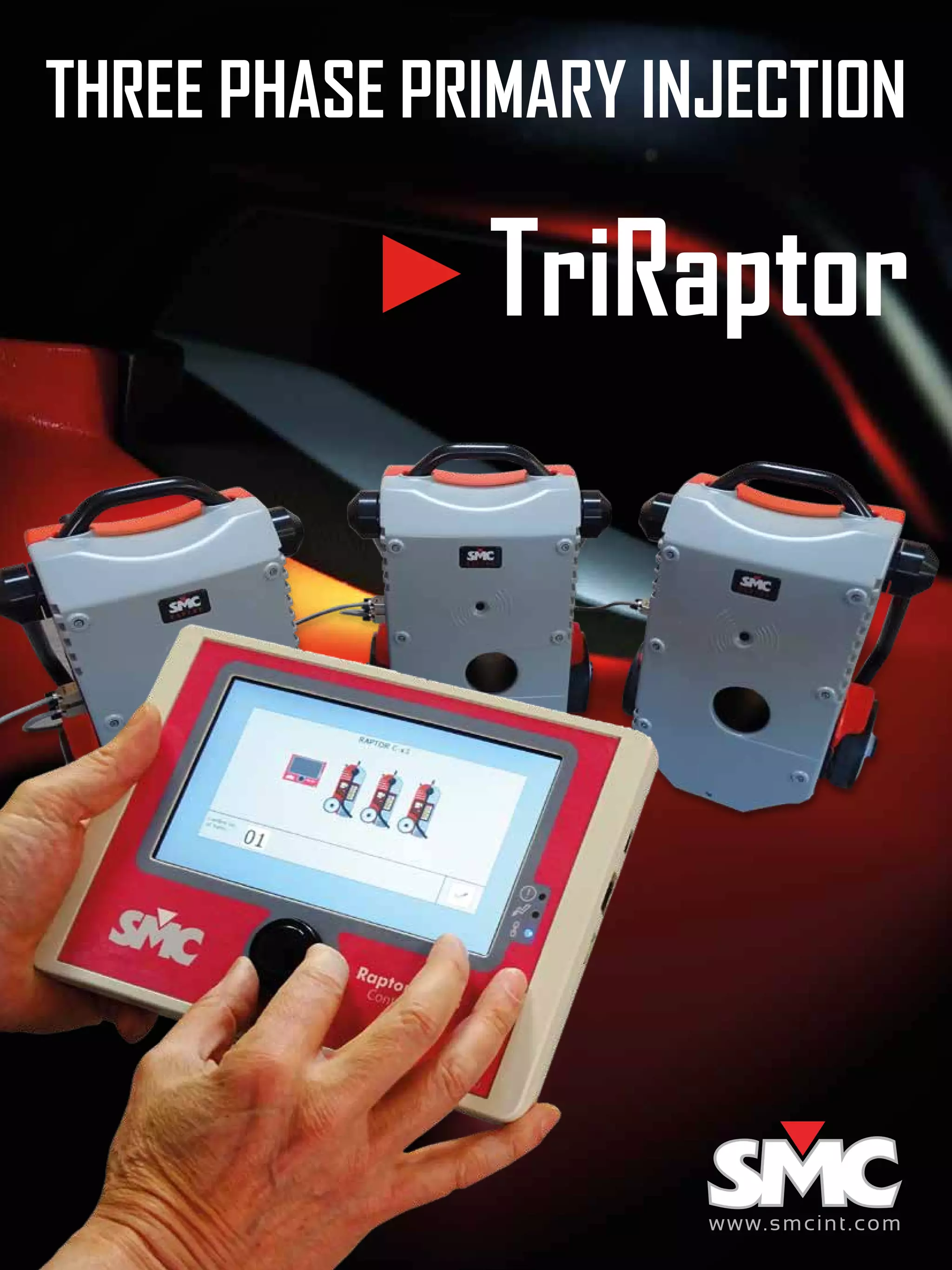
THREE PHASE PRIMARY INJECTION
TriRaptor
www.smcint.com
32
TriRaptor: Applications TriRaptor: Commissioning
Substation commissioning
Connect the TriRaptor’s three-phase output to both ends of a busbar
and let it maintain a pre-defined test current while you browse the entire
installation for inaccuracies and possible connection mistakes, quickly and
safely, using harmless voltage. Typical commissioning targets:
	 • Circuit continuity	 • Phase consistency
	 • CT ratio and polarity	 • Shorting jumpers left in place
	 • Secondary equipment connections	 • Protective relay settings
	 • Phase order	 • Grounding
	 • Differential circuits	 • Instruments
Circuit breaker testing
Single- and three-phase protective functions in low-, medium-,
and high voltage circuit breakers can be now easily tested
with the TriRaptor, thanks to its wide current range, 3 kVA
output power, and pre-selectable current values. Trip time is
automatically measured even when a secondary protective
device e.g. a relay cannot be accessed for testing.
Motor protection relays
Modern inline relays feature numerous functional options and
user-selectable settings, and use the line’s power to operate, so they
cannot be easily tested with single-phase injection. The TriRaptor
produces a stable and accurate output of up to 9 kA with 120º
between phases, and can measure operation time by monitoring the
relay’s tripping output or directly the current flow.
Example of connection
RELAY READINGS
Check measured
secondary values
INSTRUMENTATION
Verify operation
and accuracy
SECONDARY CONNECTIONS
Locate errors quickly
PHASE CONSISTENCY
Locate errors quickly
CIRCUIT INTEGRITY
Assess continuity and
proper grounding
CURRENT
TRANSFORMERS
Ratio, polarity
CIRCUIT BREAKERS
Check for adequate tripping
Using the same user-friendly philosophy as
in the single phase Raptor, the TriRaptor’s
user interface has been implemented
on a larger touch screen and furnished
with pre-defined templates that provide
ON/OFF synchronization of the three output
phases. Test current values can be preset
and dynamically adjusted individually and
time results and other measurements are
recorded and displayed for each phase.
When injecting in polarized (asymmetrical
waveform) mode, the Raptor Polarity Tester
can be used to check the entire installation
for connection errors in a matter of minutes.
TEST TEMPLATES
4
TriRaptor: Specifications
RAPTOR MS (3 units per system)
(values @240Vac,50 Hz,1 turn sec.960 mm2
,measured 25 cm on each side)
HIGH CURRENT OUTPUT
Output Current Output Voltage
No Load V (0%Imax) 0 - 1.20 Vac - Continuous
3.8 KAac (25%Imax) 0 - 0.81 Vac - Continuous
7.5 KAac (50%Imax) 0 - 0.42 Vac - 3 min
9.5 KAac (Imax) 0 - 0.22 Vac - 3 s
No Load Resolution 25 uVac
Output Frequency Same as supply’s (50/60 Hz)
Ranges 0-1 KAac/N; 0-15 KAac/N (n: number of secondary turns)
Resolution 1 Aac, 10 Aac
Accuracy ±0.2% of the value ±0.2% of the range
Phase angle ±0.25º
LOW CURRENT OUTPUT (not simultaneous with high current output)
Output Current 0 - 35 Aac (0 – 9 Aac continuous)
Voltage Output 0 - 200 Vac
Output Frequency Same as supply’s (50/60 Hz)
Isolated output Yes
Protection Fuse
AMMETER/LOW LEVEL VOLTMETER
Ammeter Ranges 0 - 0.2 / 0 - 2 / 0 - 20 Aac
Ammeter Resolution 0.1 mAac, 1 mAac, 10 mAac
Ammeter Impedance <10 mΩ
Voltmeter Ranges 0 - 30 mVac, 0 - 0, 3 Vac, 0 - 3 Vac
Voltmeter Resolution 0.01 mVac, 0.1 mVac, 1 mVac
Voltmeter Impedance >3000 KΩ
Frequency range 20 - 400 Hz
Accuracy ±0.1% of the value ±0.1% of the range
Phase angle ±0.25º
Isolated input Yes
VOLTMETER
Ranges 0 - 0.2 / 0 - 2 / 0 - 20 / 0 - 300 Vac
Resolution 0.1 mVac, 1 mVac, 10 mVac, 0.1 Vac
Impedance >120 KΩ
Frequency range 20 - 400 Hz
Accuracy ±0.1% of the value ±0.1% of the range
Phase angle ±0.25º
Isolated input Yes
BINARY INPUT
Type Dry contact / Voltage
Voltage mode Levels 1.5 V, 15 V ; Max. Voltage 250 Vac.
Time resolution 1 ms
Isolated input Yes
COMMUNICATIONS
2 x RS-485 Raptor Bus connectors from previous R-MS or 3xHH to next R-MS
GENERAL
Supply
230 V ±10%, 50/60 Hz, single phase (all the 3 units must be plugged
into the same phase and must be connected in parallel or wye)
Weight 35 Kg / 77 lb
Dimensions 550 x 440 x 230 mm / 21 ½” x 17 ½” x 9”
Working temperature 0-50º C
Storage temperature -25 to + 70 ºC
Protections MCB, overload, temperature, supply, communications, polarity
Sec. hole diameter 85 mm
Transport Wheels, folding handle, fixed handle
RAPTOR 3xHH
Mini-PC powered byWindows CE
CONTROL
Display 7” high definition color TFT
Interface Resistive touch panel + Rotary Encoder (turn & push)
LEDs Alarm, Connectivity, Power
COMMUNICATIONS
RS-485 Raptor BUS Communication with Raptor-MS
USB Connection to PC
RJ-45 Ethernet for software updates
GENERAL
Power Supply
Self-powered from Raptor-MS, or with external 5V AC/DC power
adapter with a real consumption of about 1A
Weight 1 Kg / 2 lb
Dimensions 224 x 164 x 40 mm / 8” x 6” x 1 ½”
Case
High quality injection-molded ABS. Entire backface covered with
magnet + rubber for fixation
Transport Soft nylon bag.
Connection cable 5 m / 16 ½ ft (3 no.)
Compliance
The instrument is intended for use in high-voltage substations and
industrial environments. All EuroSMC products comply to CE-marking
directives and IEC and international standards, and are designed and
manufactured in accordance with ISO-9001 quality standard.
www.smcint.com
European Office
EuroSMC S.A.
C/ Buril 69
28400 Collado Villalba -Madrid -Spain
Tel.: +34 91 849 89 80
sales@eurosmc.com
USA Office
NoramSMC Inc.
5840 South Memorial Drive - Suite 208
Tulsa - OK 74145 - USA
Tel.: +1 918 622 5725
sales@noramsmc.com
SMC Latin America Office
Cantuarias 270, Oficina 604
Miraflores, Lima 18. Peru
Tel.: +51 1 724 6146
Cell: +51 96 81 600 96
latinam@eurosmc.com
Asian Office
Unit A, 15/F, Charmhill Centre,
50 Hillwood Road,Tsim Sha Tsui,
Kowloon, Hong Kong SAR
Tel.: +852 91516 899
asia@eurosmc.com
Pleasenote:DuetothecontinuousresearchanddevelopmentbyEuroSMC,specificationsinthiscatalogmaybechangedwithoutpreviousnotice.KAECCENVersion:1

SMC TriRaptor Three-phase Primary Injection

  • 1.
    THREE PHASE PRIMARYINJECTION TriRaptor www.smcint.com
  • 2.
    32 TriRaptor: Applications TriRaptor:Commissioning Substation commissioning Connect the TriRaptor’s three-phase output to both ends of a busbar and let it maintain a pre-defined test current while you browse the entire installation for inaccuracies and possible connection mistakes, quickly and safely, using harmless voltage. Typical commissioning targets: • Circuit continuity • Phase consistency • CT ratio and polarity • Shorting jumpers left in place • Secondary equipment connections • Protective relay settings • Phase order • Grounding • Differential circuits • Instruments Circuit breaker testing Single- and three-phase protective functions in low-, medium-, and high voltage circuit breakers can be now easily tested with the TriRaptor, thanks to its wide current range, 3 kVA output power, and pre-selectable current values. Trip time is automatically measured even when a secondary protective device e.g. a relay cannot be accessed for testing. Motor protection relays Modern inline relays feature numerous functional options and user-selectable settings, and use the line’s power to operate, so they cannot be easily tested with single-phase injection. The TriRaptor produces a stable and accurate output of up to 9 kA with 120º between phases, and can measure operation time by monitoring the relay’s tripping output or directly the current flow. Example of connection RELAY READINGS Check measured secondary values INSTRUMENTATION Verify operation and accuracy SECONDARY CONNECTIONS Locate errors quickly PHASE CONSISTENCY Locate errors quickly CIRCUIT INTEGRITY Assess continuity and proper grounding CURRENT TRANSFORMERS Ratio, polarity CIRCUIT BREAKERS Check for adequate tripping Using the same user-friendly philosophy as in the single phase Raptor, the TriRaptor’s user interface has been implemented on a larger touch screen and furnished with pre-defined templates that provide ON/OFF synchronization of the three output phases. Test current values can be preset and dynamically adjusted individually and time results and other measurements are recorded and displayed for each phase. When injecting in polarized (asymmetrical waveform) mode, the Raptor Polarity Tester can be used to check the entire installation for connection errors in a matter of minutes. TEST TEMPLATES
  • 3.
    4 TriRaptor: Specifications RAPTOR MS(3 units per system) (values @240Vac,50 Hz,1 turn sec.960 mm2 ,measured 25 cm on each side) HIGH CURRENT OUTPUT Output Current Output Voltage No Load V (0%Imax) 0 - 1.20 Vac - Continuous 3.8 KAac (25%Imax) 0 - 0.81 Vac - Continuous 7.5 KAac (50%Imax) 0 - 0.42 Vac - 3 min 9.5 KAac (Imax) 0 - 0.22 Vac - 3 s No Load Resolution 25 uVac Output Frequency Same as supply’s (50/60 Hz) Ranges 0-1 KAac/N; 0-15 KAac/N (n: number of secondary turns) Resolution 1 Aac, 10 Aac Accuracy ±0.2% of the value ±0.2% of the range Phase angle ±0.25º LOW CURRENT OUTPUT (not simultaneous with high current output) Output Current 0 - 35 Aac (0 – 9 Aac continuous) Voltage Output 0 - 200 Vac Output Frequency Same as supply’s (50/60 Hz) Isolated output Yes Protection Fuse AMMETER/LOW LEVEL VOLTMETER Ammeter Ranges 0 - 0.2 / 0 - 2 / 0 - 20 Aac Ammeter Resolution 0.1 mAac, 1 mAac, 10 mAac Ammeter Impedance <10 mΩ Voltmeter Ranges 0 - 30 mVac, 0 - 0, 3 Vac, 0 - 3 Vac Voltmeter Resolution 0.01 mVac, 0.1 mVac, 1 mVac Voltmeter Impedance >3000 KΩ Frequency range 20 - 400 Hz Accuracy ±0.1% of the value ±0.1% of the range Phase angle ±0.25º Isolated input Yes VOLTMETER Ranges 0 - 0.2 / 0 - 2 / 0 - 20 / 0 - 300 Vac Resolution 0.1 mVac, 1 mVac, 10 mVac, 0.1 Vac Impedance >120 KΩ Frequency range 20 - 400 Hz Accuracy ±0.1% of the value ±0.1% of the range Phase angle ±0.25º Isolated input Yes BINARY INPUT Type Dry contact / Voltage Voltage mode Levels 1.5 V, 15 V ; Max. Voltage 250 Vac. Time resolution 1 ms Isolated input Yes COMMUNICATIONS 2 x RS-485 Raptor Bus connectors from previous R-MS or 3xHH to next R-MS GENERAL Supply 230 V ±10%, 50/60 Hz, single phase (all the 3 units must be plugged into the same phase and must be connected in parallel or wye) Weight 35 Kg / 77 lb Dimensions 550 x 440 x 230 mm / 21 ½” x 17 ½” x 9” Working temperature 0-50º C Storage temperature -25 to + 70 ºC Protections MCB, overload, temperature, supply, communications, polarity Sec. hole diameter 85 mm Transport Wheels, folding handle, fixed handle RAPTOR 3xHH Mini-PC powered byWindows CE CONTROL Display 7” high definition color TFT Interface Resistive touch panel + Rotary Encoder (turn & push) LEDs Alarm, Connectivity, Power COMMUNICATIONS RS-485 Raptor BUS Communication with Raptor-MS USB Connection to PC RJ-45 Ethernet for software updates GENERAL Power Supply Self-powered from Raptor-MS, or with external 5V AC/DC power adapter with a real consumption of about 1A Weight 1 Kg / 2 lb Dimensions 224 x 164 x 40 mm / 8” x 6” x 1 ½” Case High quality injection-molded ABS. Entire backface covered with magnet + rubber for fixation Transport Soft nylon bag. Connection cable 5 m / 16 ½ ft (3 no.) Compliance The instrument is intended for use in high-voltage substations and industrial environments. All EuroSMC products comply to CE-marking directives and IEC and international standards, and are designed and manufactured in accordance with ISO-9001 quality standard. www.smcint.com European Office EuroSMC S.A. C/ Buril 69 28400 Collado Villalba -Madrid -Spain Tel.: +34 91 849 89 80 sales@eurosmc.com USA Office NoramSMC Inc. 5840 South Memorial Drive - Suite 208 Tulsa - OK 74145 - USA Tel.: +1 918 622 5725 sales@noramsmc.com SMC Latin America Office Cantuarias 270, Oficina 604 Miraflores, Lima 18. Peru Tel.: +51 1 724 6146 Cell: +51 96 81 600 96 latinam@eurosmc.com Asian Office Unit A, 15/F, Charmhill Centre, 50 Hillwood Road,Tsim Sha Tsui, Kowloon, Hong Kong SAR Tel.: +852 91516 899 asia@eurosmc.com Pleasenote:DuetothecontinuousresearchanddevelopmentbyEuroSMC,specificationsinthiscatalogmaybechangedwithoutpreviousnotice.KAECCENVersion:1