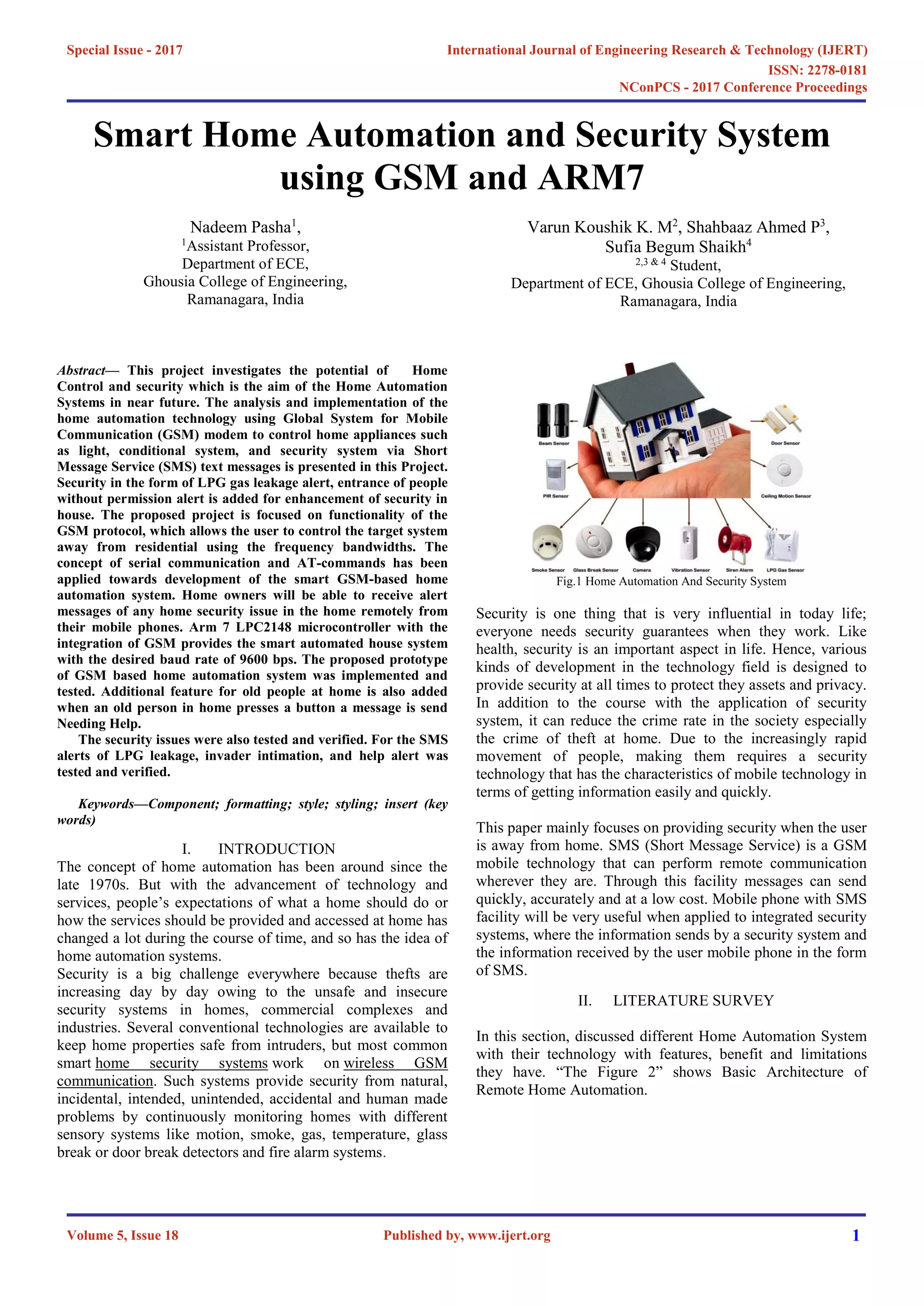
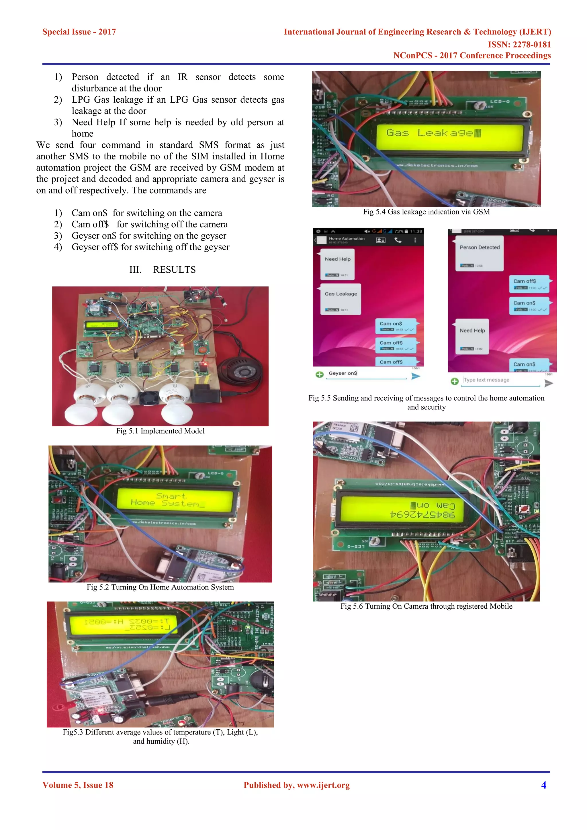
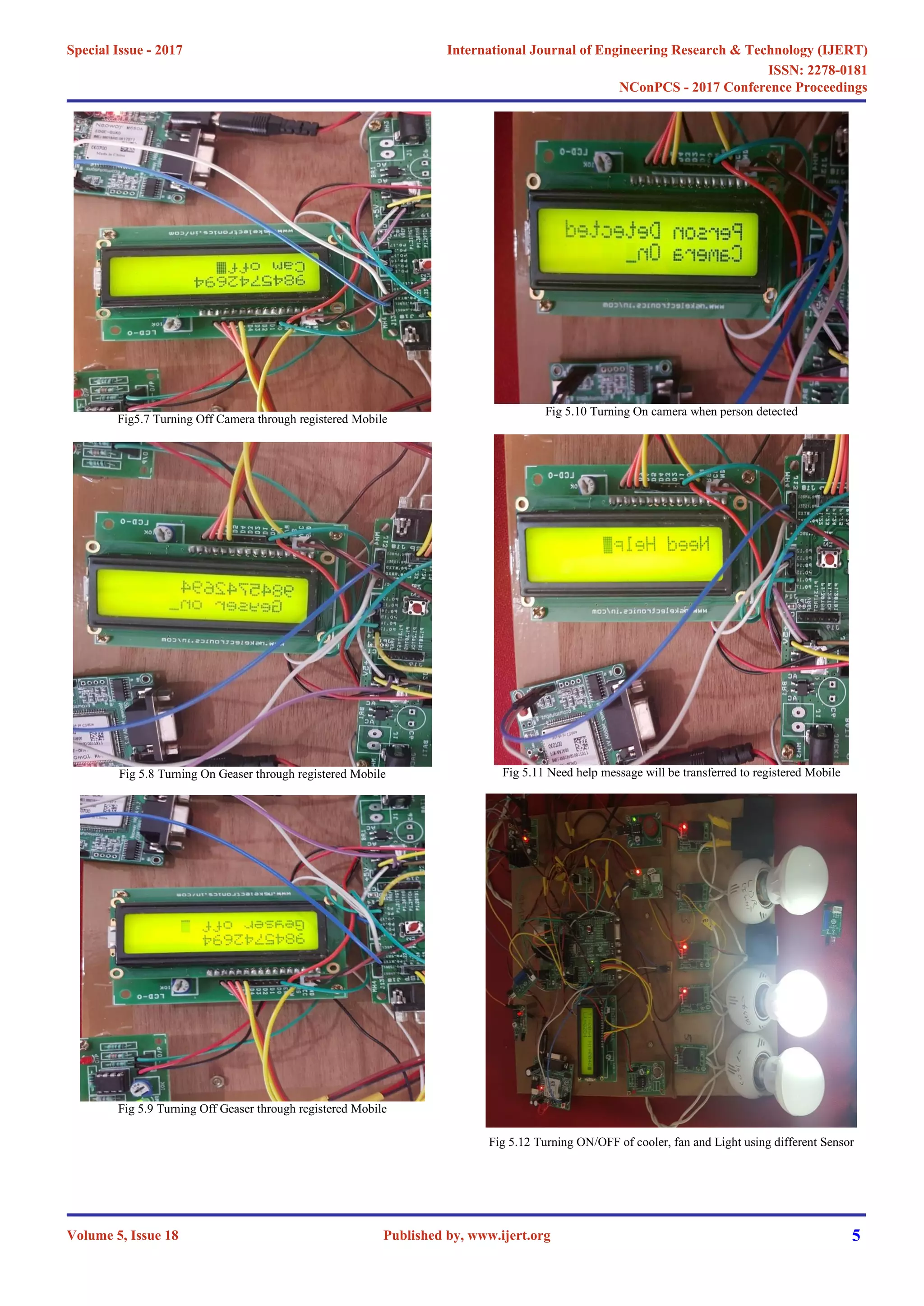
This document describes a smart home automation and security system using GSM and an ARM7 microcontroller. The system allows users to remotely control and monitor home appliances and security sensors via text messages. It includes sensors to detect temperature, humidity, light levels, infrared motion, and LPG gas leaks. Appliances like fans, lights, and a cooler can be automatically controlled based on sensor readings. Security features include CCTV activation, alarms for gas leaks or intrusions, and an emergency help button for elderly residents. The system provides energy savings and peace of mind by allowing remote home monitoring and control through a mobile phone.
![Figure 2: Basic Block Diagram of Home Automation
The Home automation system that uses Wi-Fi technology [1].
System consists of three main components; web server, which
presents system core that controls, and monitors users’ home
and hardware interface module(Arduino PCB (ready-made),
Wi-Fi shield PCB, 3 input alarms PCB, and 3 output actuators
PCB.), which provides appropriate interface to sensors and
actuator of home automation system. The System is better
from the scalability and flexibility point of view than the
commercially available home automation systems. The User
may use the same technology to login to the server web based
application. .If server is connected to the internet, so remote
users can access server web based application through the
internet using compatible web browser.
The application has been developed based on the android
system [2]. An interface card has been developed to assure
communication between the remote user, server, raspberry pi
card and the home Appliances. The application has been
installed on an android Smartphone, a web server, and a
raspberry pi card to control the shutter of windows. Android
application on a Smartphone issue command to raspberry pi
card. An interface card has been realized to update signals
between the actuator sensors and the raspberry pi card.
Cloud-based home appliance monitoring and controlling
System. Design and implement a home gateway to collect
metadata from home appliances and send to the cloud-based
data server to store on HDFS (Hadoop Distributed File
System), process them using Map Reduce and use to provide a
monitoring function to Remote user [3].
It has been implemented with Raspberry Pi through reading
the subject of E-mail and the algorithm. Raspberry Pi proves
to be a powerful, economic and efficient platform for
implementing the smart home automation [4].Raspberry pi
based home automation is better than other home automation
methods is several ways. For example, in home automation
through DTMF (dual tone multi-frequency) [11], the call
tariffis a huge disadvantage, which is not the case in their
proposed method. Also, in Web server based home
automation, the design of web server and the memory space
required is ejected by this method, because it simply uses the
already existing web server service provided by G-mail. LEDs
were used to indicate the switching action. System is
interactive, efficient and flexible.
Shih-Pang Tseng et al. [5] proposed Smart House Monitor &
Manager (SHMM), based on the ZigBee, all sensors and
actuators are connected by a ZigBee wireless network. They
designed a simple smart socket, which can remote control via
ZigBee. PC host is used as a data collector and the motion
sensing, all sensing data are transferred to the VM in the
cloud. The user can use the PC or Android phone to monitor
or control through the Internet to power-saving of the house.
Arduino microcontroller to receive user commands to execute
through an Ethernet shield. Our house network used together
both wireless ZigBee and wired X10 technologies [6]. This
system followed smart task scheduling with a heuristic for the
Resource-constrained-scheduling problem (RCPSP). The
mobile device can be either wired to the central controller
through USB cable or communicates with it wirelessly, within
the scope of the home. Arduino contains the web server
application that communicates through the HTTP protocol
with Web-based Android application. The system is highly
flexible and scalable and expandable.
The home network which monitors the appliances and sensors
and transmits data to the cloud-based data server which
manages the information and provides services for users by
transmitting data and receiving user commands from mobile
application [7]. The proposed system has good modularity and
configurability characteristics with very low power
consumption in cost efficient way.
Application developed using the Android platform controlled
and monitored from a remote location using the smart home
app and an Arduino Ethernet based micro web-server [8]. The
sensors and actuators/relays are directly interfaced to the main
controller. Proposed design offers are the control of energy
management systems such as lightings, heating, air
conditioning, security, fire detection and intrusion detection
with siren and email notifications.
Embedded system Raspberry Pi to serve as a
communication gateway between mobile devices and Konnex-
Bus (KNX) home automation systems [9]. Store the
information of all actors and sensors within a Smart Home,
instead of using separate profiles. Ensures energy-
consumption could be reduced, compared to a standard
desktop computer.
III METHODOLOGY
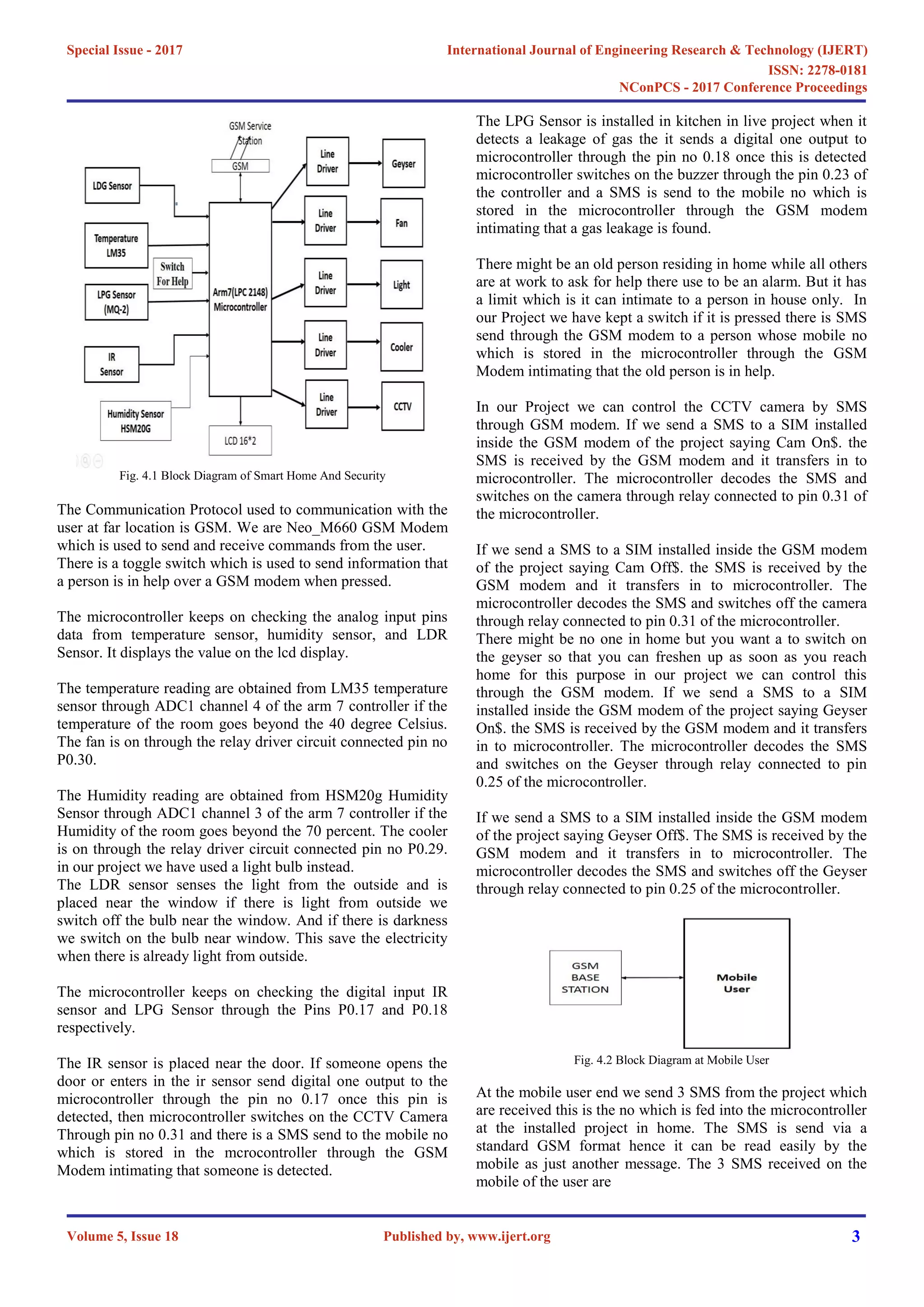
The microcontroller amr7 is the hearth of the Project. It
controls working of whole project. Its constantly senses
information from the sensor and controls different home
appliances through activators.
This project has 5 sensors
1) LPG sensor
2) Temperature Sensor
3) humidity sensor
4) IR sensor
5) LDR Sensor
This sensor has 5 relays to control different appliances. The
appliances which are there in this projects are
1) Fan
2) Light
3) Cooler (Light used demo purpose)
4) Geyser (Light used demo purpose)
5) CCTV Camera
The project uses 16*2 LCD to display temperature, humidity
and Darkness.
International Journal of Engineering Research & Technology (IJERT)
ISSN: 2278-0181
Published by, www.ijert.org
NConPCS - 2017 Conference Proceedings
Volume 5, Issue 18
Special Issue - 2017
2](https://image.slidesharecdn.com/smart-home-automation-and-security-system-using-gsm-and-arm7-ijertconv5is180081-220330092147/75/smart-home-automation-and-security-system-using-gsm-and-arm7-IJERTCONV5IS18008-1-pdf-2-2048.jpg)
![CONCLUSIONS
We have combined home security and automation in single
project and added a help button for an old age person in our
project. This is will provide optimum energy usage and
provide security to system if a person enters without
permission or gas is leaked a message is sent through GSM
modem. Energy saving is done through controlling home
appliances depending on the preferred conditions
automatically.
In future the along GSM modem we can include GPRS
modem or Wi-Fi module to connect to internet and optimize
our project in terms of IOT. Akk the sensor could be
connected to IOT cloud server and the video captured can also
be sent to the IOT cloud server over an internet protocol.
REFERENCES
[1] Ahmed ElShafee, Karim AlaaHamed,” Design and Implementation of a
WiFi Based Home Automation System”, International Journal of
Computer, Electrical, Automation, Control and Information Engineering
Vol: 6, No: 8, 2012.
[2] HayetLamine and HafedhAbid , ”Remote control of a domestic
equipment from an Android application based on Raspberry pi card”,
IEEE transaction 15th international conference on Sciences and
Techniques of Automatic control & computer engineering - STA'2014,
Hammamet, Tunisia, December 21-23, 2014.
[3] YunCui, MyoungjinKim, YiGu, Jong-jinJung, and HankuLee, “Home
Appliance Management System for Monitoring Digitized Devices Using
Cloud Computing Technology in Ubiquitous Sensor Network
Environment”,Hindawi Publishing Corporation International Journal of
Distributed Sensor Networks Volume 2014, Article ID 174097.
[4] Jain Sarthak,VaibhavAnant and Goyal Lovely ,“Raspberry Pi based
Interactive Home Automation System through E-mail.”,IEEE
transaction,2014 International Conference on Reliability, Optimization
and Information Technology ICROIT 2014, India, Feb 6-8 2014.
[5] Shih-Pang Tseng, Bo-Rong Li, Jun-Long Pan, and Chia-JuLin,”An
Application of Internet of Things with Motion Sensing on Smart
House“, 978-1-4799-6284-6/14 c ⃝ 2014 IEEE.
[6] Kim Baraka, Marc Ghobril, Sami Malek, RouwaidaKanj, Ayman Kayssi
“Low cost Arduino/Android-based Energy-Efficient Home Automation
System with Smart Task Scheduling” , 2013 Fifth International
Conference on Computational Intelligence, Communication Systems and
Networks.
[7] Kim Baraka, Marc Ghobril, Sami Malek, RouwaidaKanj, Ayman Kayssi
,”Smart Power Management System For Home Appliances And
Wellness Based On Wireless Sensors Network And Mobile
Technology”, ,2015 XVIII AISEM Annual Conference, 978-1-4799-
8591-3/15©2015 IEEE
[8] Shiu Kumar,” UBIQUITOUS SMART HOME SYSTEM USING
ANDROID APPLICATION “, International Journal of Computer
Networks & Communications (IJCNC) Vol.6, No.1, January 2014.
[9] Jan Gebhardt, Michael Massoth, Stefan Weber and TorstenWiens ,
“Ubiquitous Smart Home Controlling Raspberry Embedded System”,
UBICOMM: The Eighth International Conference on Mobile Ubiquitous
Computing, Systems, Services and Technologies, 2014.
[10] Andrea Zanella, Nicola Bui, Angelo Castellani, Lorenzo Vangelista, and
Michele Zorzi, “Internet of Things for Smart Cities”, IEEE INTERNET
OF THINGS JOURNAL, VOL. 1, NO. 1, FEBRUARY 2014.
International Journal of Engineering Research & Technology (IJERT)
ISSN: 2278-0181
Published by, www.ijert.org
NConPCS - 2017 Conference Proceedings
Volume 5, Issue 18
Special Issue - 2017
6](https://image.slidesharecdn.com/smart-home-automation-and-security-system-using-gsm-and-arm7-ijertconv5is180081-220330092147/75/smart-home-automation-and-security-system-using-gsm-and-arm7-IJERTCONV5IS18008-1-pdf-6-2048.jpg)