Downloaded 227 times

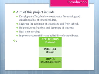


The document outlines a project for an IoT-based school bus monitoring system aimed at enhancing the safety and tracking of school children during commutes. The proposed solution utilizes a low-cost ESP8266 microcontroller with real-time GPS tracking and RFID identification for students, providing features like emergency services contact, attendance marking, and fleet management. Despite certain limitations, such as RFID range and reliance on Wi-Fi, the system demonstrates cost-effectiveness, being developed at around $20 compared to existing systems costing $150-$200.


