Downloaded 38 times
![3
Model Outline Engine Chassis Body Body Electrical
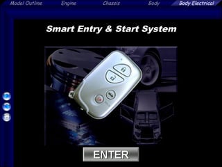
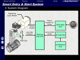
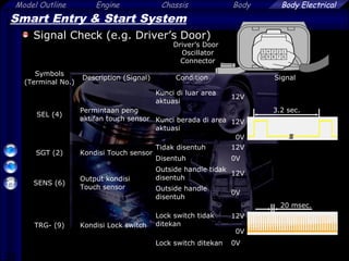
Smart Entry & Start System (G A/T)
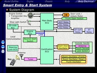
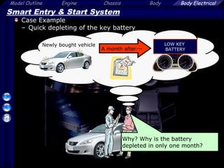
Overall
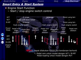
– Memungkinkan mengoperasikan Manual lock/unlock, engine start,
membuka pintu bagasi hanya dengan membawa kunci ( Remote )
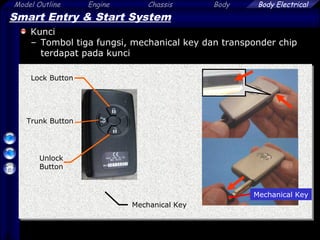
[Kunci]
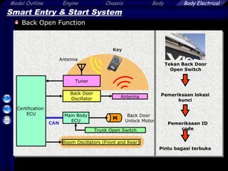
[Back Door Opening (hanya membuka) Function]
[Door Lock / Unlock Function] [Engine Start Function]](https://image.slidesharecdn.com/smartentryformaster-141005065114-conversion-gate02/85/Smart-entry-for-master-3-320.jpg)
![23
Model Outline Engine Chassis Body Body Electrical
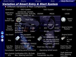
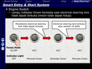
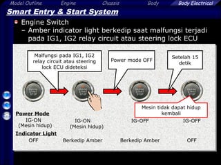
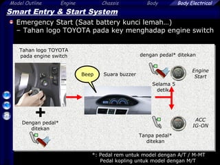
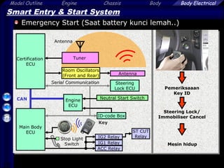
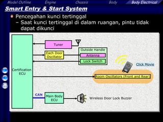
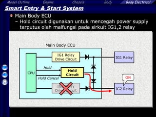
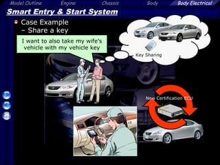
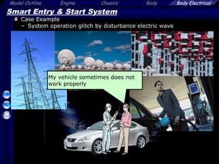
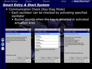
Smart Entry & Start System
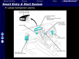
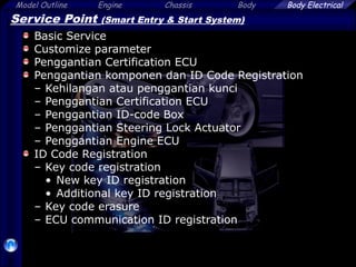
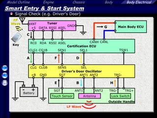
Smart Entry & Start System Cancel Function
– Fungsi ini dapat meng-cancel fungsi – fungsi berikut :
• Entry Start function, Door lock/unlock function, luggage opening
function, prevention of key confinement, warning function dan
memory call function
[System Cancel Function]
Cancellation Procedure
1
Unlock sekali dengan tombol
UNLOCK*
2 Buka pintu pengemudi
3
Unlock dua kali dengan tombol
UNLOCK *
4
Buka dan tutup pintu pengemudi 2
kali (terakhir, terbuka)
5
Unlock dua kali dengan tombol
UNLOCK *
6
Buka dan tutup pintu pengemudi
sekali (terakhir, terbuka)
7 Tutup pintu pengemudi
Interval
Dalam 5 sec.
Dalam 5 sec.
Dalam 30 sec.
Dalam 30 sec.
Dalam 30 sec.
Dalam 5 sec.
Prasyarat: IG-OFF, Pintu pengemudi ditutup dan diunlock
*: Mengoperasikan tombol kunci](https://image.slidesharecdn.com/smartentryformaster-141005065114-conversion-gate02/85/Smart-entry-for-master-23-320.jpg)
![24
Model Outline Engine Chassis Body Body Electrical
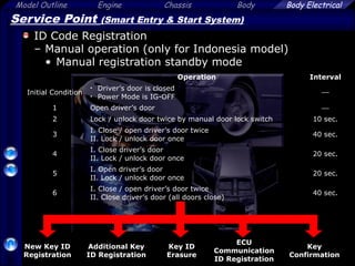
Smart Entry & Start System
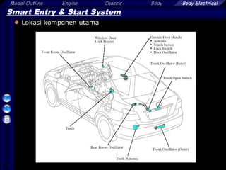
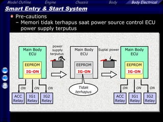
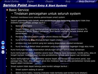
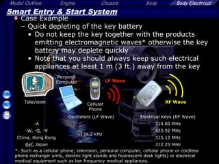
Fungsi yang lain
– Smart Entry & Start
Fungsi sistem yang lain
Parked for
a long time
[Battery Saving Function]
Activate
IG-ON
[Fungsi peringatan]
Deactivate
Wireless Door
Lock Buzzer
Beep
Warning Light
Perubahan Interval (Setiap 250 ms menjadi
750 ms)
• Tidak ada respon lebih dari 5 hari
Penonaktifan
• Tidak ada respon lebih dari 14 hari
• Berada dalam pendeteksian area lebih dari 10
menit tanpa pengoperasian
Pengaktifan kembali
Operasikan door lock/unlock tanpa fungsi smart
Passenger](https://image.slidesharecdn.com/smartentryformaster-141005065114-conversion-gate02/85/Smart-entry-for-master-24-320.jpg)
![26
Model Outline Engine Chassis Body Body Electrical
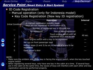
Smart Entry & Start System
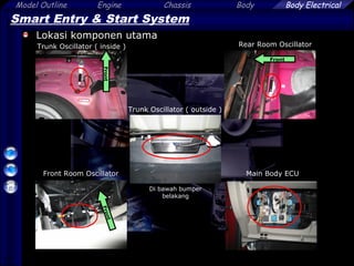
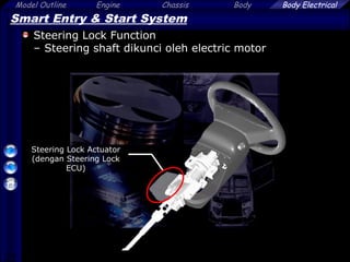
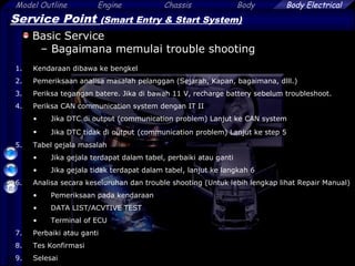
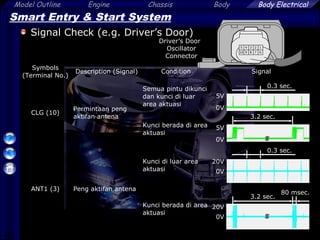
Steering Lock Actuator
– Steering lock system terdiri dari sebagai berikut :
[Steering Lock Actuator]
Steering
Column Tube
Lock Bar
Hall ICs
Gears
Steering
Lock ECU
Steering
Lock Motor
Lift
Magnet](https://image.slidesharecdn.com/smartentryformaster-141005065114-conversion-gate02/85/Smart-entry-for-master-26-320.jpg)
![Model Outline Engine Chassis Body
42
Body Electrical
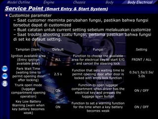
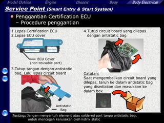
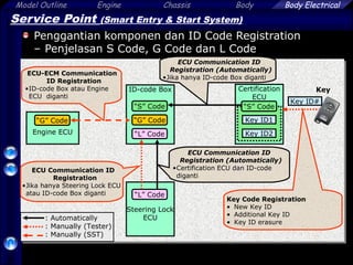
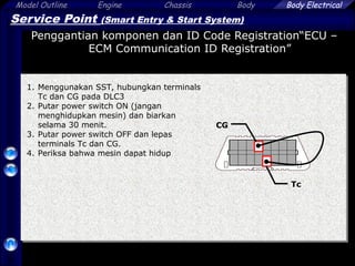
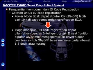
Service Point (Smart Entry & Start System)
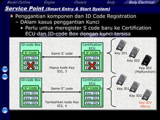
Penggantian komponen dan ID Code Registration
– Dalam kasus semua Kunci hilang atau penggantian
Kunci
NOTE:
Jika semua kunci tidak diregister selama registrasi kunci yang lain, kunci tersebut tidak
dapat diregistrasi kemudian saat penggantian Certification ECU
*: Perlu penggantian, walaupun Certification ECU dan ID-code Box dalam kondisi normal
Jumlah Kunci
Condition before registration
Sedikitnya 1
Kunci
tersedia
1. Menggunakan Kunci tersisa, hapus kode kunci yang hilang [Key Code
Erasure]
2. Register kunci tambahan jika diperlukan
[Key Code Registration] (Additional key ID registration)
Semua Kunci
hilang
1. Ganti ID-code box dan Certification ECU*
2. Register semua Kunci [Key Code Registration] (New key ID
registration)
3. Register ID-code Box – Engine ECU communication ID
[ECU – ECM Communication ID Registration]](https://image.slidesharecdn.com/smartentryformaster-141005065114-conversion-gate02/85/Smart-entry-for-master-42-320.jpg)
![Model Outline Engine Chassis Body
47
Body Electrical
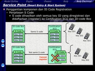
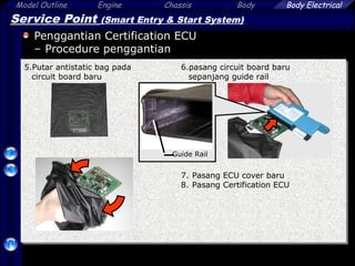
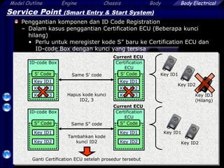
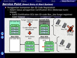
Service Point (Smart Entry & Start System)
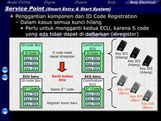
Penggantian komponen dan ID Code Registration
– Dalam kasus penggantian Certification ECU
Jumlah kunci
Condition before registration
Key ID codes can be
registered / erased
Key ID codes cannot be either
registered / erased
Semua kunci
terpasang
1. Ganti certification ECU
2. Register semua kunci [Key Code Registration] (New key ID
registration)
Beberapa
kunci hilang
1. Hapus kode kunci
[Key Code Erasure]
2. Register kunci tersisa
[Key Code Registration]
(Additional key ID registration)
3. Ganti certification ECU
4. Register semua kunci[Key Code
Registration]
(New key ID registration)
1. Ganti certification ECU dan
ID-code box*
2. Register semua kunci [Key Code
Registration]
(New key ID registration)
3. Register ID-code Box – engine ECU
communication ID
[ECU – ECM Communication ID
Registration]
Catatan:
Jika beberapa kunci tidak diregister selama meregistrasi kunci yang lain, kunci tersebut
tidak dapat diregistrasi kemudian
*: Perlu penggantian, meskipun ID-code box dalam kondisi normal](https://image.slidesharecdn.com/smartentryformaster-141005065114-conversion-gate02/85/Smart-entry-for-master-47-320.jpg)
![Model Outline Engine Chassis Body
53
Body Electrical
Service Point (Smart Entry & Start System)
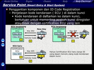
Penggantian komponen dan ID Code Registration
– Dalam kasus penggantian ID-code box
Jumlah kunci
Kondisi sebelum registrasi
Setidaknya
tersedia 1
kunci
1. Ganti ID-code box
2. Register recognition kode di dalam ECU
[Key code registration]
3. Register ID-code Box – Engine ECU communication ID
[ECU – ECM Communication ID Registration]](https://image.slidesharecdn.com/smartentryformaster-141005065114-conversion-gate02/85/Smart-entry-for-master-53-320.jpg)
![Model Outline Engine Chassis Body
54
Body Electrical
Service Point (Smart Entry & Start System)
Penggantian komponen dan ID Code Registration
– Dalam kasus penggantian Steering Lock Actuator
Jumlah kunci
Kondisi sebelum registrasi
Setidaknya
tersedia 1
kunci
1. Ganti Steering Lock Actuator
2. Register recognition kode di dalam ECUs
[ECU Communication ID Registration]
Catatan:
Dalam kondisi berikut mesin tidak dapat hidup untuk pertama kali (dikarenakan Steering
Lock ECU tidak dapat secara tepat mendeteksi posisi steering lock bar)
[Steering lock ECU baru belum menyimpan posisi steering lock bar]
• Setelah mengganti Steering Lock Actuator
• Setelah mengisi/mengganti battery yang kosong
Buka dan tutup pintu pengemudi untuk menghidupkan mesin](https://image.slidesharecdn.com/smartentryformaster-141005065114-conversion-gate02/85/Smart-entry-for-master-54-320.jpg)
![Model Outline Engine Chassis Body
55
Body Electrical
Service Point (Smart Entry & Start System)
Penggantian komponen dan ID Code Registration
– Dalam kasus penggantian engine ECU
Jumlah kunci
Kondisi sebelum registrasi
Setidaknya
tersedia 1
kunci
1. Ganti Engine ECU
2. Register ID-code Box – Engine ECU communication ID
[ECU – ECM Communication ID Registration]
Catatan:
Jangan mengoperasikan switch power mode ON/OFF lebih dari 20 kali sebelum
menyelesaikan “ECU – ECM Communication ID Registration” jika tidak ganti Engine ECU](https://image.slidesharecdn.com/smartentryformaster-141005065114-conversion-gate02/85/Smart-entry-for-master-55-320.jpg)
![Model Outline Engine Chassis Body
61
Body Electrical
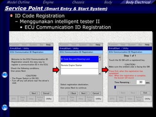
Service Point (Smart Entry & Start System)
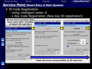
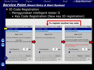
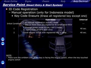
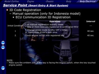
ID Code Registration
– Menggunakan intelligent tester II
• Key Code Registration (New key ID registration)
[5]
[2]](https://image.slidesharecdn.com/smartentryformaster-141005065114-conversion-gate02/85/Smart-entry-for-master-61-320.jpg)
![Model Outline Engine Chassis Body
62
Body Electrical
[5]
[2]
Service Point (Smart Entry & Start System)
ID Code Registration
– Menggunakan intelligent tester II
• Key Code Registration (Additional key ID registration)](https://image.slidesharecdn.com/smartentryformaster-141005065114-conversion-gate02/85/Smart-entry-for-master-62-320.jpg)
![Model Outline Engine Chassis Body
64
Body Electrical
Service Point (Smart Entry & Start System)
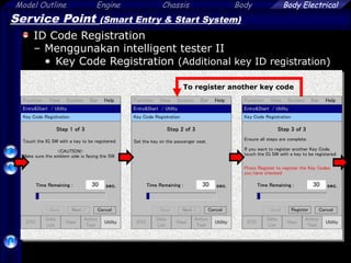
ID Code Registration
– Menggunakan intelligent tester II
• Key Code Registration (Additional key ID registration)
[4]
[3]](https://image.slidesharecdn.com/smartentryformaster-141005065114-conversion-gate02/85/Smart-entry-for-master-64-320.jpg)
![Model Outline Engine Chassis Body
65
Body Electrical
[3]
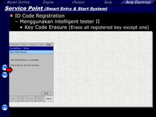
Service Point (Smart Entry & Start System)
ID Code Registration
– Menggunakan intelligent tester II
• Key Code Erasure (Erase all registered key except one)](https://image.slidesharecdn.com/smartentryformaster-141005065114-conversion-gate02/85/Smart-entry-for-master-65-320.jpg)
![Model Outline Engine Chassis Body
74
Body Electrical
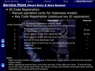
Service Point (Smart Entry & Start System)
ID Code Registration
– Manual operation (only for Indonesia model)
• Key confirmation
Operation Interval
Initial Condition
• In manual registration standby mode
• One or more keys are registered to certification ECU
1
I. Change power mode to ON / OFF 3 times
II. Open/close driver’s door once
40 sec.
[Number of registered key]
ex.) When 3 keys are registering
Wireless Door
Lock Buzzer
OFF
ON
1 2 3](https://image.slidesharecdn.com/smartentryformaster-141005065114-conversion-gate02/85/Smart-entry-for-master-74-320.jpg)

1. The document describes the components and operation of a smart entry and start system used in Toyota vehicles. It details the key fob, antenna locations, control modules and circuits involved in remote locking, unlocking, engine starting and other functions. 2. The system uses transponder technology and radio frequency signals to detect the presence of the key fob and authorize various functions when the fob is within range. It allows drivers to operate doors, trunk and start the engine without inserting a key. 3. Troubleshooting procedures are outlined, including checking for faults in communication networks and control modules. The importance of fully-charged key fob batteries and avoiding sources of radio interference are also emphasized.