Downloaded 114 times


![function sixthsense
v=videoinput('winvideo');
preview(v)
snap=getsnapshot(v);
i1=ycbcr2rgb(snap);
[a b c]=size(i1);
x=0;
y=0;
z=0;
for m=1:a
for n=1:b
if((i1(m,n,1)<=150)&&(i1(m,n,1)>=90)&&(i1(m,n,2)
>=230)&&(i1(m,n,2)<=255)&&(i1(m,n,3)>=60)&&
(i1(m,n,3)<=170))
x=x+1;
end
end
end](https://image.slidesharecdn.com/sixthsensingrobot-130629040448-phpapp01/85/Sixth-sensing-robot-20-320.jpg)
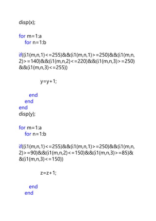
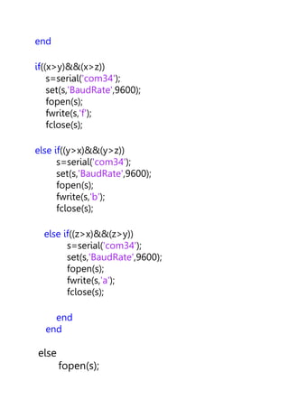
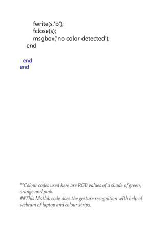

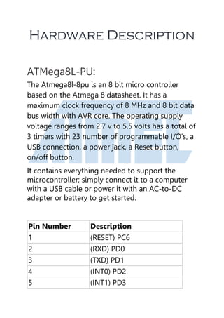
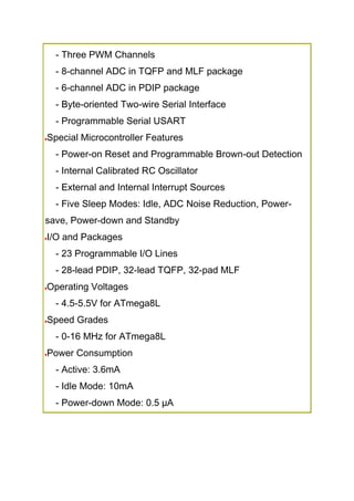
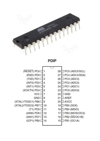
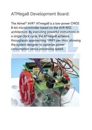
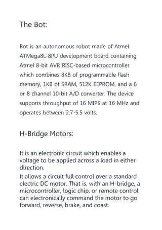
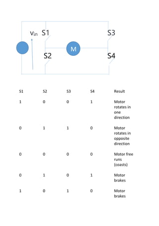
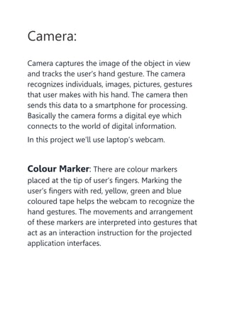
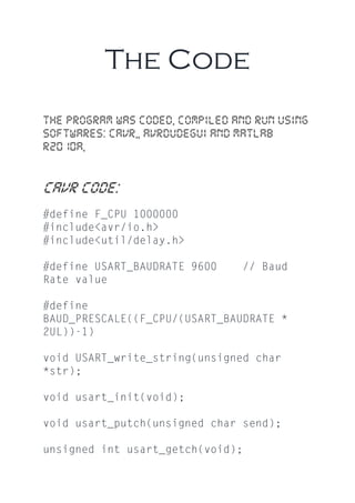
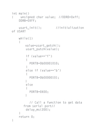
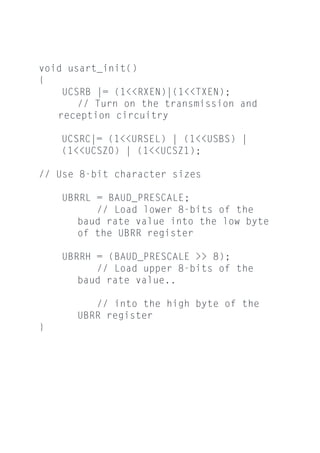
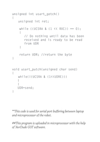
The document describes a project to create a sixth sense robot using an Atmel ATMega8 microcontroller development board. The robot uses computer vision techniques to track colored markers on a user's fingers to interpret gestures and send commands to control motors on the robot. Specifically, it captures images with a webcam, processes them to detect different colored markers, and sends signals to an H-bridge motor controller to move the robot forward, backward, or turn based on the detected gesture. The code uses color thresholding algorithms to identify pixels matching the colors of each marker and determine the gesture.


