SEPARATING DUST
•
0 likes•62 views

A mill, as well as most of the production plants, is a set of machines connected to each other and crossed by a continuous (or not) product flow rate; one of its main characteristics is that product flow between the machines can also occur by means of pneumatic transport systems.

Recommended
Recommended
More Related Content
Similar to SEPARATING DUST
Similar to SEPARATING DUST (20)
More from Milling and Grain magazine
More from Milling and Grain magazine (20)
Recently uploaded
Recently uploaded (20)
SEPARATING DUST
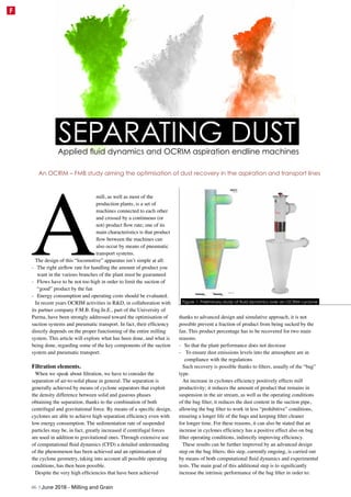
- 1. A mill, as well as most of the production plants, is a set of machines connected to each other and crossed by a continuous (or not) product flow rate; one of its main characteristics is that product flow between the machines can also occur by means of pneumatic transport systems. The design of this “locomotive” apparatus isn’t simple at all: - The right airflow rate for handling the amount of product you want in the various branches of the plant must be guaranteed - Flows have to be not too high in order to limit the suction of “good” product by the fan - Energy consumption and operating costs should be evaluated. In recent years OCRIM activities in R&D, in collaboration with its partner company F.M.B. Eng.In.E., part of the University of Parma, have been strongly addressed toward the optimisation of suction systems and pneumatic transport. In fact, their efficiency directly depends on the proper functioning of the entire milling system. This article will explore what has been done, and what is being done, regarding some of the key components of the suction system and pneumatic transport. Filtration elements. When we speak about filtration, we have to consider the separation of air-to-solid phase in general. The separation is generally achieved by means of cyclone separators that exploit the density difference between solid and gaseous phases obtaining the separation, thanks to the combination of both centrifugal and gravitational force. By means of a specific design, cyclones are able to achieve high separation efficiency even with low energy consumption. The sedimentation rate of suspended particles may be, in fact, greatly increased if centrifugal forces are used in addition to gravitational ones. Through extensive use of computational fluid dynamics (CFD) a detailed understanding of the phenomenon has been achieved and an optimisation of the cyclone geometry, taking into account all possible operating conditions, has then been possible. Despite the very high efficiencies that have been achieved thanks to advanced design and simulative approach, it is not possible prevent a fraction of product from being sucked by the fan. This product percentage has to be recovered for two main reasons: - So that the plant performance does not decrease - To ensure dust emissions levels into the atmosphere are in compliance with the regulations Such recovery is possible thanks to filters, usually of the “bag” type. An increase in cyclones efficiency positively effects mill productivity; it reduces the amount of product that remains in suspension in the air stream, as well as the operating conditions of the bag filter, it reduces the dust content in the suction pipe, allowing the bag filter to work in less “prohibitive” conditions, ensuring a longer life of the bags and keeping filter cleaner for longer time. For these reasons, it can also be stated that an increase in cyclones efficiency has a positive effect also on bag filter operating conditions, indirectly improving efficiency. These results can be further improved by an advanced design step on the bag filters; this step, currently ongoing, is carried out by means of both computational fluid dynamics and experimental tests. The main goal of this additional step is to significantly increase the intrinsic performance of the bag filter in order to: SEPARATING DUST An OCRIM – FMB study aiming the optimisation of dust recovery in the aspiration and transport lines Applied fluid dynamics and OCRIM aspiration endline machines Figure 1: Preliminary study of fluid dynamics over an OCRIM cyclone 46 | June 2016 - Milling and Grain F
- 2. - Further increase bag useful life - Reduce the filter size even maintaining the same filtering surface - Contain pressure losses and, consequently, the energy consumption of the entire plant. To achieve these objectives the research will be focused on three different aspects: 1. Optimisation of filtration material 2. Investigation on the maximisation of the filtering surface; 3. Optimisation of filter design parameters. Research, as well as that conducted for cyclones, proceeds through a close synergy between experimental and simulative activities. This is possible thanks to close cooperation with FMB Eng.In.E, a branch of the University of Parma. FMB Eng.In.E. . FMB is, for OCRIM, an integrated research platform that combines in-depth theoretical knowledge in the field of simulation, modeling and virtualisation of industrial processes, with the advantages associated with the academic world, which are, for example, the availability of high-level know-how, laboratories and advanced equipment. An important investment has been made in order to install at the Department of Industrial Engineering of the University of Parma a pilot plant able to experiment and test different components of a suction system. The plant consists of a series of pipes, a bag filter and a fan, and offers the possibility to connect all the components that have to be tested (pneumatic conveying sections, cyclones, aspirated machines, etc.). This system is very important in order to collect all the data necessary to interpret and validate the results of fluid dynamic simulations. Validation is an essential step in the development process as it allows us to improve the reliability of the simulation tool that can then be used, subsequently, to test different design configurations without performing, every time, an experimental test. The combined use of fluid dynamics simulation and experimentation allows us to obtain robust and reliable results with lower cost for experimentation, design and prototyping compared to a traditional experimental approach. 7-Cs.nlAARSEN5039 What does the future hold for feed mill technology? The future is more efficiency, while increasing feed quality. The future is higher production and lower energy consumption. The future is fully automated lines producing lower costs per ton. The future is smart engineering concepts using state-of-the-art technology. The future is here today, with smart feed mills from Van Aarsen. Feed mills of the future are here today www.aarsen.com 2015-11-18, Grain & Feed Milling Adv.indd 1 18-11-15 12:37 Figure 2: OCRIM Test bed at the University of Parma for the study of fluid dynamics Milling and Grain - June 2016 | 47 F
- 3. Optimisation of filtration material Put simply, the purpose of the filter material is to hold dust and let flow air, opposing the least possible resistance to the flowing of the same (low pressure losses). Research is therefore directed towards materials with the same cut- off dimension (minimum size of particles retained) but with an higher air permeability than material currently used. Laboratory tests and, in parallel, simulations allowed the identification of some materials able to ensure the same filtering capability but with a significant reductions in both energy consumption and filtering surface required. These advantages can be translated into an improvement in energy efficiency of the plant and in a reduction of the number of bags and, consequently, of the filter size. Investigation on the maximisation of the filtering surface In addition to research on filtration material, an investigation on the geometry of the filter element, in order to maximise the useful surface and then reduce the number of necessary bags, is being conducted. Optimisation of filter design parameters Different solutions and configurations, with the aim of limiting the abrasive effects and particles impact on filter elements, can be evaluated by means of simulation and experimental tests. By changing the geometry, it is possible to distribute the flow more uniformly inside the filter, in order to avoid the presence of excessively stressed elements. The optimal geometry is that which maximises two separation effects inside the machine: the cyclonic effect, which is able to remove the fraction of larger dust, and the filtration effect, which is able to retain the finer particles that “escape” from the cyclonic effect. The cyclonic effect inside the filter also has a protective action against the sleeves for two reasons: - It removes that fraction of heavier powders that have a higher abrasive effect - It allows the air / powder mixture to dissipate much of its energy before its “impact” with bags, thus ensuring a longer life of the filter elements. Thanks to fluid dynamics simulation it is possible to “virtually evaluate” different filter configurations, in terms of both the number and arrangement of the bags in order to identify the configuration that allows to minimise the impact velocity of the air/powder mixture against filter elements. Fluid dynamics simulation in fact, unlike a classical experimental approach, allows us to obtain a complete picture of what happens inside the filter, this means that, moment by moment, the flow distribution inside the filter, and consequently the values of pressure and air velocity at all points of the fluid domain can be known. This is a big advantage with respect to an experimental approach, which only provides data at those points in which measuring tools are positioned. Simulation therefore, allows us to obtain a global evaluation of the performance of each configuration, it allows us to test more configurations with respect to a traditional approach, and thus allows us to find, more accurately and more quickly, the optimal configuration of the system. Thanks to the detailed study of the air flows achievable by means of fluid dynamics simulation, for example, it was possible to define the optimum height of the flat bottom, in the case of a filter with sweeper, in order to minimise its impacts on the cyclonic effect ensuring, also in this case, a longer life of the filter elements. CFD Modeling of different filtering materials Figure 4: Preliminary simulation of fluid dynamics over sections inside the filter 48 | June 2016 - Milling and Grain F