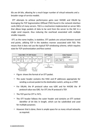
Sabarigirivason k
lOM
oAR cP
SD|30016045
Unit -1 SDN: INTRODUCTION
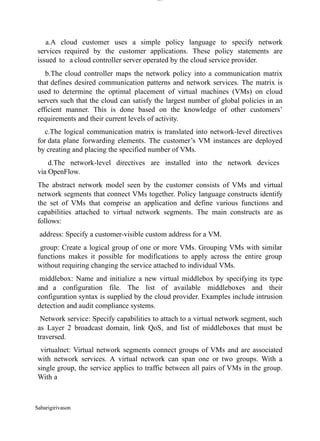
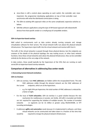
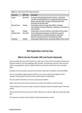
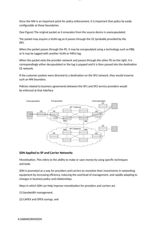
Evolving Network Requirements
Software-defined networking is an evolving network architecture beheading the traditional
network architecture focusing its disadvantages in a limited perspective. A couple of decades
before, programming and networking were viewed as different domains which today with the
lights of SDN bridging themselves together. This is to overcome the existing challenges faced by
the networking domain and an attempt to propose cost-efficient effective and feasible solutions.
Changes to the existing network architecture are inevitable considering the volume of connected
devices and the data being held together. SDN introduces a decoupled architecture and brings
customization within the network making it easy to configure, manage, and troubleshoot.
Software-defined networking, or SDN, is a strategy that splits the control plane from the
forwarding plane and pushes management and configuration to centralized consoles.
SDN is now over 10 years old. When the history of SDN began, many people thought gleaming
software-defined networks would replace tightly coupled, vertically integrated network products.
The massive data centers of Amazon, Facebook and Google all moved to SDN, but why isn't
SDN everywhere?
Well, it is, even if it's not always called SDN.
The principles of SDN are alive and well, thanks, in part, to cloud computing. All of today's
major cloud providers use SDN. As more workloads move to cloud environments, more
organisations will use SDN. Let's look at the evolution of SDN to see how it got to this point.
The role of vendors in the evolution of SDN
In the corporate data center, practically everything is virtualized -- from workloads to servers to
networking. VMware, the king of the virtualized data center, bought Nicira and rebranded its
SDN- style networking as VMware NSX. Hundreds of thousands of virtual machines in data
centers around the world run on NSX, which means they run on SDN.
Cisco -- the company that initially scoffed at SDN, because it threatened the status quo --
eventually hopped on the bandwagon and introduced an SDN variant, Cisco
Application Centric Infrastructure, to the market, trying to embrace the future without letting go of
the past.
4.
lOM
oAR cP
SD| 30016045
Othernetworking companies began to turn to SDN, as well. Juniper Networks embraced SDN in
its Contrail products, and Arista Networks integrated SDN principles into its Extensible
Operating System in an attempt to bring a new software-defined cloud networking to the market.
Smaller vendors, like Dell Technologies and Hewlett Packard Enterprise, used the SDN strategy to
open up their platforms, split tightly coupled hardware and software apart, and inject customer
choice into the process. While not necessarily SDN, this open networking strategy is an important
part of the evolution of SDN's overall viability.
Problems in Traditional Network Devices
● They are vendor specific
● Hardware & Software is bundled together
● Very costly
● New features can only be added at the will of the vendor.
Sabarigirivason k
5.
Sabarigirivason k
lOM
oAR cP
SD|30016045
● Client can only request the features, vendor will decide whether to add those features or
not & the time frame in which these features will become available is at the sole
discretion of the vendor.
● Devices are function specific. You can not make your router behave like load balancer or
make your switch behave like a firewall or vice versa.
● If your network consists of hundred of these devices, each device has to be configured
individually. There is no centralized management.
● Innovations are very rare. Last 3 decades have not seen many innovations in networking.
Whereas Compute and storage industry has seen drastic changes such as compute
virtualization & storage virtualization. Networking has not been able to keep pace with
other ingredients of Cloud Computing.
Advantages of SDN
● The network is programmable and hence can easily be modified via the controller rather
than individual switches.
● Switch hardware becomes cheaper since each switch only needs a data plane.
● Hardware is abstracted, hence applications can be written on top of the controller
independent of the switch vendor.
● Provides better security since the controller can monitor traffic and deploy security
policies. For example, if the controller detects suspicious activity in network traffic, it
can reroute
or drop the packets.
Disadvantages of SDN
● The central dependency of the network means a single point of failure, i.e. if the
controller gets corrupted, the entire network will be affected.
● The use of SDN on a large scale is not properly defined and explored.
Why SDN is Important
● Better Network Connectivity: SDN provides very better network connectivity for sales,
services, and internal communications. SDN also helps in faster data sharing.
● Better Deployment of Applications: Deployment of new applications, services, and many
business models can be speed up using Software Defined Networking.
6.
Sabarigirivason k
lOM
oAR cP
SD|30016045
● Better Security: Software-defined network provides better visibility throughout the
network. Operators can create separate zones for devices that require different levels of
security. SDN networks give more freedom to operators.
● Better Control with High Speed: Software-defined networking provides better speed than
other networking types by applying an open standard software-based controller.
In short, it can be said that- SDN acts as a “Bigger Umbrella or a HUB” where the rest of other
networking technologies come and sit under that umbrella and get merged with another platform
to bring out the best of the best outcome by decreasing the traffic rate and by increasing the
efficiency of data flow.
Components of Software Defining Networking (SDN)
The three main components that make the SDN are:
1. SDN Applications: SDN Applications relay requests or networks through SDN
Controller using API.
2. SDN controller: SDN Controller collects network information from hardware and
sends this information to applications.
3. SDN networking devices: SDN Network devices help in forwarding and data
processing tasks.
7.
lOM
oAR cP
SD| 30016045
TheSDN Approach
In traditional networks, the control and data plane are embedded together as a single unit. The
control plane is responsible for maintaining the routing table of a switch which determines the
best path to send the network packets and the data plane is responsible for forwarding the packets
based on the instructions given by the control plane. Whereas in SDN, the control plane and data
plane are separate entities, where the control plane acts as a central controller for many data
planes.
Sabarigirivason k
8.
lOM
oAR cP
SD| 30016045
Thereare many approaches that lead to the development of today’s Software Defined
Networks(SDN). They are:
● Force
● 4D approach
● Ethane
FORCES(Forwarding and control element separation):
The idea of separation of data plane(forwarding element) and control plane was first proposed by
FORCES. It is said that hardware-based forwarding entities are controlled by a software-based
control plane.
FORCES can be implemented in two ways:
1. The forwarding element and control plane are located within the same network
device
2. The control element is taken off the device and placed in a separate system.
Sabarigirivason k
9.
lOM
oAR cP
SD| 30016045
4Dapproach:
The 4D approach has four planes that control
● Decision
● Dissemination
● Discovery
● Data
It follows three principles:
Network-level objectives: The objectives should be stated in terms of the whole network instead
of individual devices. So that there won’t be any need to depend on proprietary devices.
Network-wide view: Decisions should be made based on the understanding of the whole
network’s traffic, topology, and events. Actions should be taken based on considering a network-
wide view.
Direct control: The control plane elements should directly be able to control the data plane
elements. It should have the ability to program the forwarding table on individual devices.
Sabarigirivason k
10.
lOM
oAR cP
SD| 30016045
Ethane:
Ethanespecifies network-level access of users which is defined by network
administrators. Ethane is the exact forerunner of Software Defined Networks(SDN)
Sabarigirivason k
11.
lOM
oAR cP
SD| 30016045
Principlesof Ethane
● High-level policies should inspect the network
● Routing should follow High-level policies.
● There should be a connection between packets and their origin in the network.
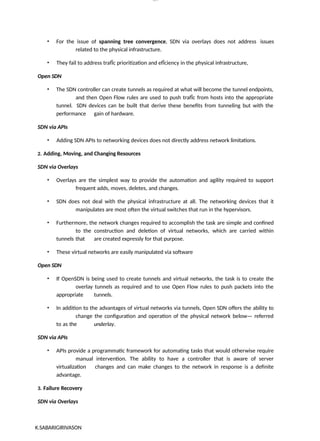
SDN Layers
The layers communicate via a set of interfaces called the north-bound APIs(between the
application and control layer) and southbound APIs(between the control and infrastructure layer).
Different Models of SDN
There are several models, which are used in SDN:
1. Open SDN
2. SDN via APIs
3. SDN via Hypervisor-based Overlay Network
4. Hybrid SDN
1. Open SDN: Open SDN is implemented using the OpenFlow switch. It is a straightforward
implementation of SDN. In Open SDN, the controller communicates with the switches using
south- bound API with the help of OpenFlow protocol.
Sabarigirivason k
12.
lOM
oAR cP
SD| 30016045
2.SDNvia APIs: In SDN via API, the functions in remote devices like switches are invoked
using conventional methods like SNMP or CLI or through newer methods like Rest API.
Here, the devices are provided with control points enabling the controller to manipulate the
remote devices using APIs.
3.SDN via Hypervisor-based Overlay Network: In SDN via the hypervisor, the
configuration of physical devices is unchanged. Instead, Hypervisor based overlay networks are
created over the physical network. Only the devices at the edge of the physical network are
connected to the virtualized networks, thereby concealing the information of other devices in the
physical network.
Sabarigirivason k
13.
lOM
oAR cP
SD| 30016045
4.Hybrid SDN: Hybrid Networking is a combination of Traditional Networking with software-
defined networking in one network to support different types of functions on a network.
Difference between SDN and Traditional Networking
Software Defined Networking Traditional Networking
Software Defined Network is a virtual
networking approach.
A traditional network is the old conventional
networking approach.
Sabarigirivason k
14.
Sabarigirivason k
lOM
oAR cP
SD|30016045
Software Defined Network is centralized
control.
Traditional Network is distributed control.
This network is programmable. This network is non programmable.
Software Defined Network is the open
interface.
A traditional network is a closed interface.
In Software Defined Network data plane
and control, the plane is decoupled by
software.
In a traditional network data plane and
control plane are mounted on the same
plane.
1.4 & 1.5 SDN Data Plane ,Control plane and Application Plane
SDN Data Plane
While the Control Plane supervises and directs, the Data Plane is responsible for the actual
movement of data from one system to another. It is the workhorse that delivers data to end users
from systems and vice versa.
Some examples of data planes include:
● Ethernet networks
● Wi-Fi networks
15.
Sabarigirivason k
lOM
oAR cP
SD|30016045
● Cellular networks
● Satellite communications
Data planes can also include virtualized networks, like those created using virtual private networks
(VPNs) or software-defined networks (SDNs). Additionally, data planes can include dedicated
networks, like the Internet of Things (IoT) or industrial control systems.
Data planes allow organizations to quickly and securely transfer data between systems. For
example, a data plane can enable the transfer of data between a cloud-based application and a
local system. This functionality can be beneficial for organizations that need to access data from
multiple systems or that need to quickly transfer large amounts of data.
By using dedicated networks, organizations can keep data secure through encryption, dedicated
networks, and access monitoring to prevent unauthorized access of data.
SDN Control Plane
The Control Plane is a crucial component of a network, tasked with making decisions on how
data should be managed, routed, and processed. It acts as a supervisor of data,
coordinating communication between different components and collecting data from the Data
Plane.
Control Planes utilize various protocols, such as:
● Routing protocols (like BGP, OSPF, and IS-IS)
● Network management protocols (SNMP)
● Application layer protocols (HTTP and FTP)
These protocols often employ software-defined networking (SDN) to create virtual networks and
manage their traffic. Virtual networks, facilitated by SDN, are instrumental in managing data traffic
at an enterprise level. They enable organizations to:
● Segment traffic
● Prioritize important data flows
● Isolate traffic from different parts of the network
Data Plane vs. Control Plane: What Are the Key Differences?
The main differences between control and data planes are their purpose and how they
communicate
between different systems. The control plane decides how data is managed, routed, and processed,
while the data plane is responsible for the actual moving of data. For example, the control plane
decides how packets should be routed, and the data plane carries out those instructions by
forwarding the packets.
16.
Sabarigirivason k
lOM
oAR cP
SD|30016045
Along with doing different jobs, control planes and data planes exist in different areas. While the
control plane runs in the cloud, the data plane runs in the data processing area.
They also use different functions to do their jobs. Control planes use protocols to communicate
between different systems, mostly common routing protocols like BGP, OSPF, and IS-IS or
network management protocols like SNMP. These protocols enable the control plane to make
decisions on how data should be managed, routed, and processed.
Data planes use dedicated networks to communicate between different systems. Examples of
dedicated networks used in data planes include Ethernet and Wi-Fi networks, cellular networks,
satellite communications, virtualized networks, and dedicated networks used in industrial control
systems or IoT. These networks enable the data plane to deliver data to end users from systems
and vice versa.
While both the Control Plane and Data Plane are integral to network management, they perform
distinct roles. The table below outlines some of the key differences between the two:
Control Plane Data Plane
Determines how data should be managed,
routed, and processed
Responsible for moving packets from source
to destination
Builds and maintains the IP routing table Forwards actual IP packets based on the
Control Plane’s logic
Packets are processed by the router to update
the routing table
Forwards packets based on the built logic of
the Control Plane
1.5.3 Software-Defined Networking (SDN) Application
17.
lOM
oAR cP
SD| 30016045
1.5.2.1SDN application environment
Internal SDN Applications
External SDN Applications
Software-defined networking (SDN) application is a software program which is designed to
perform a task in a software-defined networking environment. It is that approach to computer
networking that not only allows network administrators to change programmatically, control,
initialize, and manage network behaviour dynamically through open interfaces but also provides
the concept of lower-level functionality. SDN applications also help in enlarging and substituting
upon functions that are accomplished in the hardware devices of a regular network through
firmware.
Sabarigirivason k
Applications that are hosting the rest of the OpenDaylight controller software and are deployed
internally, run inside the container. These applications must be written in the native language which
is Java for ODL. Internal SDN applications must also adhere to the execution and design
constraints of the controller. It must also execute in the same Java Machine as the controller
which means that these types of the application must run locally with the controller. It can also
access the MD-SAL
applications and Java APIs of the controller running inside the controller’s OSGi container.
Applications that are hosting the rest of the Open Daylight controller software, and are deployed
externally, run outside the container. Any language can be used for writing External SDN
applications that are scripting languages such as Bash. These applications can be run remotely
18.
lOM
oAR cP
SD| 30016045
TopApplication and Service that can benefit from SDN are:
Security services
Network Monitoring and Intelligence
which means on a different host than the controller. These applications will also use the application
providing Restful access to their services and REST API provided by the controller.
The modern virtualization ecosystem supports specific virtual service that is running within the
network layer. It means an incorporating function like NFV into SDN platforms. This type of
network security creates a genuinely proactive environment that is capable of risk reduction and
responds to the incidents very quickly. Whenever a violation occurs, every second is quite critical
to stop the attack. It is also essential to identify the attack and also to ensure that other network
components are safe from the attack. As the organization in the modern era becomes even more
digitized, and as the network layer becomes even more critical, we will see even more attacks
and more advanced sophisticated advanced persistent threats. You will be able to create a more
proactive environment that is capable of responding to the changes if you integrate potent
services into the SDN layer.
Sabarigirivason k
Modern SDN technologies help in abstracting one of the most critical layers within the data
centre that is the network. Network architectures are very much complicated and have to handle a
lot more data than ever before. This means it’s critical to know what is following through your
environment. Do you have remission issues on a port? What will happen if you are running
19.
lOM
oAR cP
SD| 30016045
BandwidthManagement
heterogeneous network architecture? Or, are you passing a lot of traffic and are heavily
virtualized through the network architecture? All of these challenges or issues are diminished if
you have a solid network monitoring and intelligence layer. However, you also gain benefit and
true insight if you integrate these technologies into your SDN architecture. Even optimization,
alerting, hypervisor integration, port configurations, and traffic flow can be incorporated into
network monitoring and intelligence technologies. Also, these types of agile systems will also
help you to monitor network traffic between your cloud ecosystem and your data centre.
With the help of SDN applications, operators can use bandwidth management to ensure the end
users to receive online video watching and optimal browsing experiences. This SDN
application can also monitor the bandwidth requirements then provision user flows to match the
latency and
bandwidth requirements of the layer 7 application. This type of application-aware approach to
bandwidth management will also ensure a better user experience with zero buffering through
better video playback. At this stage in the game, there is little doubt that SDN is becoming a
reality in operator networks.
However, it is the SDN applications that will really bring powerful improvements to the
operator’s business and networks, beyond the immediate impact of simpler management of the
network. And so the network infrastructure providers need to start mapping out this future to
calculate all the potential that can be provided by SDN.
Sabarigirivason k
20.
Sabarigirivason k
lOM
oAR cP
SD|30016045
Content Availability
Regulation and Compliance-Bound Applications
High –Performance Applications
By acting and thinking ahead on SDN applications now, network infrastructure operators and
providers will be able to rapidly evolve to provide flexible, customized networks that can entirely
enhance their own bottom lines and can also enhance the end user experience.
There will be content servers used for media delivery or caching, on a service-provider edge
network. These are installed by the content delivery network or operator service providers.
Content that is to be served to the users is distributed and preoccupied across multiple content
servers and also across various geographies in some cases.
SDN apps will be able to provision flows in the network based on the availability and types of
the content which is built to handle content availability. SDN applications can also check the
availability of the content in the content servers before routing requests to servers. A content-
routing application will provide intelligence on its availability along with enabling discovery of
content in the content servers.
This intelligence can be further used to route requests to the correct servers wherever the
content is residing. Therefore, SDN application will direct requests from those websites which
are non- cache-able and that generate active content to a server that provides active content
rather than a caching server which significantly reduces network discontinuation.
Major cloud vendors are now providing the capability to work and store with compliance and
regulation-bound workloads. Now organizations have the option to extend architectures which
have initially been very limited because of regulation into the cloud and distributed
environments. How can you segment the traffic? How can you ensure that regulation and
compliance workloads are persistently monitored and secured? Here SDN can be a great help for
you.
Network points, network traffic travelling between switches, and even hypervisors can be
controlled in SDN architecture. You should also remember that this layer abstracts virtual
hardware and functions controls. This powerful layer can then span various virtualization points,
locations, and even cloud locations.
We are all seeing a rise in new types of application technologies. The delivery of rich apps like
graphics design software, engineering, CAD, and GIS is allowed by virtualization. Traditionally,
21.
lOM
oAR cP
SD| 30016045
DistributedApplication Control and Cloud Integration
these workloads are required bare-metal architectures with their own connections. However, with
the help of virtualization, VDI can help in creating powerful desktop experiences and applications
are streamed. We can also see the integration of SDN into application control at the network
layer. All of these functions like segmenting heavy traffic, securing confidential data, creating
powerful QoS policies, and even creating threshold alerts around bottlenecks within SDN will
help to support rich and high-performance applications which are being delivered through
virtualization.
The capability to extend across the entire data centre is one of the most significant benefits of
SDN. This type of agility integrates distributed cloud, locations and the organization as a whole.
SDN also allows for critical network traffic to pass between various locations irrespective of the
type of underlying network architecture. You also permit easier movement of data between cloud
locations and data centre by abstracting critical network controls. You can utilise powerful APIs
to not only integrate with a cloud provider, but you can also control specific network services as
well because SDN is a form of network virtualization. While keeping your business agile, this
allows you to manage your workloads granularly.
SDN applications are being used by organizations for a lot of the functions; however, these were
few of the main features to consider. You should understand how SDN applications can
positively impact your business and your data centre. SDN fundamentally simplifies the entire
networking layer and provides you granular control over your distributed data centre
ecosystem, services, and applications.
Sabarigirivason k
22.
Sabarigirivason k
lOM
oAR cP
SD|30016045
UNIT - 2 SDN DATA PLANE AND CONTROL PLANE
Data Plane functions and protocols
SDN Data Plane
The SDN data plane, referred to as the resource layer in ITU-T Y.3300 and also often
referred to as the infrastructure layer, is where network forwarding devices perform the transport
and processing of data according to decisions made by the SDN control plane. The important
characteristic of the network devices in an SDN network is that these devices perform a simple
forwarding function, without embedded software to make autonomous decisions.
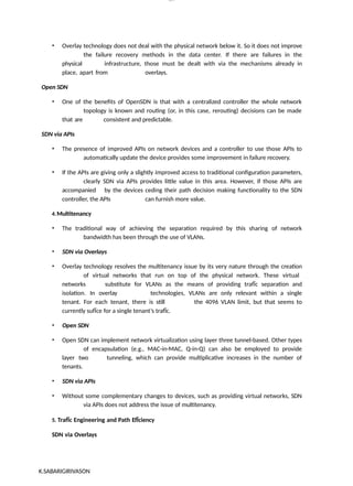
Data Plane Functions
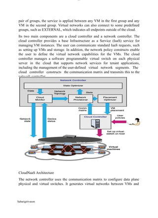
Figure 4.2 illustrates the functions performed by the data plane network devices (also
called data plane network elements or switches). The principal functions of the network device
are the following:
Also, SDN helps you to design a business capable of adjusting to changes in the industry and
market shifts. This also allows your organization to be truly productive and agile.
23.
lOM
oAR cP
SD| 30016045
FIGURE4.2 Data Plane Network Device
Control support function: Interacts with the SDN control layer to support programmability
via resource-control interfaces. The switch communicates with the controller and the controller
manages the switch via the OpenFlow switch protocol.
Data forwarding function: Accepts incoming data flows from other network devices and
end systems and forwards them along the data forwarding paths that have been computed and
established according to the rules defined by the SDN applications.
These forwarding rules used by the network device are embodied in forwarding tables that
indicate for given categories of packets what the next hop in the route should be. In addition to
simple forwarding of a packet, the network device can alter the packet header before forwarding,
or discard the packet. As shown, arriving packets may be placed in an input queue, awaiting
processing by the network device, and forwarded packets are generally placed in an output
queue, awaiting transmission.
The network device in Figure 4.2 is shown with three I/O ports: one providing control
communication with an SDN controller, and two for the input and output of data packets. This is
a simple example. The network device may have multiple ports to communicate with multiple
SDN controllers, and may have more than two I/O ports for packet flows into and out of the
device.
Sabarigirivason k
24.
lOM
oAR cP
SD| 30016045
DataPlane Protocols
Figure 4.2 suggests the protocols supported by the network device. Data packet flows consist of
streams of IP packets. It may be necessary for the forwarding table to define entries based on
fields in upper-level protocol headers, such as TCP, UDP, or some other transport or application
protocol. The network device examines the IP header and possibly other headers in each packet
and makes a forwarding decision.
The other important flow of traffic is via the southbound application programming interface
(API), consisting of OpenFlow protocol data units (PDUs) or some similar southbound API
protocol traffic.
OpenFlow Protocol
The OpenFlow protocol describes message exchanges that take place between an OpenFlow
controller and an OpenFlow switch. Typically, the protocol is implemented on top of TLS,
providing a secure OpenFlow channel.
The OpenFlow protocol enables the controller to perform add, update, and delete actions to
the
Sabarigirivason k
25.
lOM
oAR cP
SD| 30016045
flowentries in the flow tables. It supports three types of messages (see Table 4.2
):
Sabarigirivason k
26.
lOM
oAR cP
SD| 30016045
Controllerto switch: These messages are initiated by the controller and, in some cases, require
a response from the switch. This class of messages enables the controller to manage the logical
state of the switch, including its configuration and details of flow and group table entries. Also
included in this class is the Packet-out message. This message is sent by the controller to a
switch when that switch sends a packet to the controller and the controller decides not to drop the
packet but to direct it to a switch output port.
Asynchronous: These types of messages are sent without solicitation from the controller. This
class includes various status messages to the controller. Also included is the Packet-in
message, which may be used by the switch to send a packet to the controller when there is no
flow table match.
Symmetric: These messages are sent without solicitation from either the controller or the
switch. They are simple yet helpful. Hello messages are typically sent back and forth between
the controller and switch when the connection is first established. Echo request and reply
messages can be used by either the switch or controller to measure the latency or bandwidth of a
controller- switch connection or just verify that the device is up and running. The Experimenter
message is used to stage features to be built in to future versions of OpenFlow.
In general terms, the OpenFlow protocol provides the SDN controller with three types
of information to be used in managing the network:
Event-based messages: Sent by the switch to the controller when a link or port
change occurs.
Flow statistics: Generated by the switch based on traffic flow. This information enables the
controller to monitor traffic, reconfigure the network as needed, and adjust flow parameters to
meet QoS requirements.
Encapsulated packets: Sent by the switch to the controller either because there is an explicit
action to send this packet in a flow table entry or because the switch needs information for
establishing a new flow.
The OpenFlow protocol enables the controller to manage the logical structure of a switch,
without regard to the details of how the switch implements the OpenFlow logical architecture.
Flow table
In Software-Defined Networking (SDN), the "Flow Table" plays a crucial role in the data plane
of network devices, particularly in switches. The Flow Table is where rules for packet forwarding
Sabarigirivason k
27.
Sabarigirivason k
lOM
oAR cP
SD|30016045
are stored and processed. Let's delve into the specifics:
1.Functionality: The Flow Table is a fundamental component of SDN switches. It's akin to a
database where rules, known as flow entries, are stored. Each flow entry consists of match
fields and corresponding actions.
2.Match Fields: These fields define the characteristics of packets that the switch will examine
to determine whether they match a particular flow entry. Common match fields include source
and destination addresses, ports, VLAN tags, and packet header information (e.g., IP protocol,
TCP/UDP ports).
3.Actions: Once a packet matches a flow entry, the switch executes specific actions
associated with that entry. Actions can include forwarding the packet out a particular port,
dropping the packet, modifying packet headers, or sending the packet to the controller for
further processing.
4.Priority and Wildcard Entries: Flow entries in the table have priorities assigned to them.
When a packet matches multiple flow entries, the entry with the highest priority is selected.
Additionally, wildcard entries can match multiple packets based on common criteria, simplifying
rule management.
5.Flow Table Lookup: When a packet arrives at the switch, it is compared against the flow
entries in the table using the match fields. This process is known as a flow table lookup. If a
match is found, the corresponding actions are executed. If no match is found (a table miss), the
packet is often forwarded to the controller for further handling.
6.Flow Table Management: The SDN controller is responsible for managing the flow table
entries. It can dynamically add, modify, or remove entries based on network conditions, policies,
or events. This dynamic control allows for flexible and programmable packet forwarding
behavior.
7.Flow Table Capacity: The capacity of the flow table varies depending on the capabilities of
the switch hardware and the SDN controller's software. Larger capacity allows for more complex
forwarding behavior and support for a greater number of concurrent flows.
8. Flow Table Aging and Eviction: Flow entries may have a limited lifetime, after which they
28.
Sabarigirivason k
lOM
oAR cP
SD|30016045
are removed from the table. This process, known as aging, helps manage resource usage and
ensures that the flow table remains up-to-date. Entries may also be evicted to make room for
new entries when the table reaches its capacity.
9.Performance Considerations: Efficient flow table lookup is crucial for maintaining
network performance. Switches employ various techniques, such as caching and hardware
acceleration, to optimize lookup speed and reduce latency.
10.Security and Policy Enforcement: The flow table is a central point for enforcing
network security policies. By carefully configuring flow entries, administrators can control
traffic flows, implement access control policies, and mitigate security threats.
In summary, the Flow Table is a critical component of SDN switches, facilitating flexible and
programmable packet forwarding based on predefined rules. Its management and optimization are
key considerations for achieving efficient and secure network operation in SDN environments.
Flow Table Structure
29.
lOM
oAR cP
SD| 30016045
Matchfields: Used to select packets that match the values in the fields.
Priority: Relative priority of table entries. This is a 16-bit field with 0 corresponding to the
lowest priority. In principle, there could be 216 = 64k priority levels.
Sabarigirivason k
30.
lOM
oAR cP
SD| 30016045
Counters:Updated for matching packets. The OpenFlow specification defines a variety of
counters. Table 4.1 lists the counters that must be supported by an OpenFlow switch.
Instructions: Instructions to be performed if a match occurs.
Timeouts: Maximum amount of idle time before a flow is expired by the switch. Each
flow
entry has an idle_timeout and a hard_timeout associated with it. A nonzero hard_timeout field
causes the flow entry to be removed after the given number of seconds, regardless of how many
packets it has matched. A nonzero idle_timeout field causes the flow entry to be removed when
it has matched no packets in the given number of seconds.
Cookie: 64-bit opaque data value chosen by the controller. May be used by the controller to
filter flow statistics, flow modification and flow deletion; not used when processing packets.
Flags: Flags alter the way flow entries are managed; for example, the flag
OFPFF_SEND_FLOW_REM triggers flow removed messages for that flow entry.
Match Fields Component
The match fields component of a table entry consists of the following required fields (see
part b of Figure 4.5):
Ingress port: The identifier of the port on this switch on which the packet arrived. This may
be a physical port or a switch-defined virtual port. Required in ingress tables.
Egress port: The identifier of the egress port from action set. Required in egress tables.
Ethernet source and destination addresses: Each entry can be an exact address, a bitmasked
value for which only some of the address bits are checked, or a wildcard value (match any
value).
Ethernet type field: Indicates type of the Ethernet packet payload.
IP: Version 4 or 6.
IPv4 or IPv6 source address, and destination address: Each entry can be an exact address, a
bitmasked value, a subnet mask value, or a wildcard value.
TCP source and destination ports: Exact match or wildcard value.
UDP source and destination ports: Exact match or wildcard value.
The preceding match fields must be supported by any OpenFlow-compliant switch.
The following fields may be optionally supported.
Physical port: Used to designate underlying physical port when packet is received on a logical
port.
Metadata: Additional information that can be passed from one table to another during the
processing of a packet. Its use is discussed subsequently.
VLAN ID and VLAN user priority: Fields in the IEEE 802.1Q virtual LAN header. SDN
support for VLANs is discussed in Chapter 8, “NFV Functionality.”
IPv4 or IPv6 DS and ECN: Differentiated Services and Explicit Congestion
Notification
Sabarigirivason k
31.
lOM
oAR cP
SD| 30016045
fields.
SCTPsource and destination ports: Exact match or wildcard value for Stream Transmission
Control Protocol.
ICMP type and code fields: Exact match or wildcard value.
ARP opcode: Exact match in Ethernet Type field.
Source and target IPv4 addresses in ARP payload: Can be an exact address, a bitmasked
value, a subnet mask value, or a wildcard value.
IPv6 flow label: Exact match or wildcard.
ICMPv6 type and code fields: Exact match or wildcard value.
IPv6 neighbor discovery target address: In an IPv6 Neighbor Discovery message.
IPv6 neighbor discovery source and target addresses: Link-layer address options in an IPv6
Neighbor Discovery message.
MPLS label value, traffic class, and BoS: Fields in the top label of an MPLS label stack.
Provider bridge traffic ISID: Service instance identifier.
Tunnel ID: Metadata associated with a logical port.
TCP flags: Flag bits in the TCP header. May be used to detect start and end of TCP
connections.
IPv6 extension: Extension header.
Thus, OpenFlow can be used with network traffic involving a variety of protocols and
network services. Note that at the MAC/link layer, only Ethernet is supported. Therefore,
OpenFlow as currently defined cannot control Layer 2 traffic over wireless networks.
Each of the fields in the match fields component either has a specific value or a wildcard
value, which matches any value in the corresponding packet header field. A flow table may
include a table-miss flow entry, which wildcards all match fields (every field is a match
regardless of
value) and has the lowest priority.
We can now offer a more precise definition of the term flow. From the point of view of an
individual switch, a flow is a sequence of packets that matches a specific entry in a flow table.
The definition is packet oriented, in the sense that it is a function of the values of header fields
of
the packets that constitute the flow, and not a function of the path they follow through the
network. A combination of flow entries on multiple switches defines a flow that is bound to a
specific path.
Flow Table Pipeline
A switch includes one or more flow tables. If there is more than one flow table, they are
organized as a pipeline, with the tables labeled with increasing numbers starting with zero. The
Sabarigirivason k
32.
lOM
oAR cP
SD| 30016045
useof multiple tables in a pipeline, rather than a single flow table, provides the SDN
controller with considerable flexibility.
The OpenFlow specification defines two stages of processing:
Ingress processing: Ingress processing always happens, beginning with Table 0, and uses
the
identity of the input port. Table 0 may be the only table, in which case the ingress processing is
simplified to the processing performed on that single table, and there is no egress processing.
Egress processing: Egress processing is the processing that happens after the determination of
the output port. It happens in the context of the output port. This stage is optional. If it occurs, it
may involve one or more tables. The separation of the two stages is indicated by the numerical
identifier of the first egress table. All tables with a number lower than the first egress table must
be used as ingress tables, and no table with a number higher than or equal to the first egress
table can be used as an ingress table.
Pipeline processing always starts with ingress processing at the first flow table; the packet
must be first matched against flow entries of flow Table 0. Other ingress flow tables may be
used depending on the outcome of the match in the first table. If the outcome of ingress
processing is to forward the packet to an output port, the OpenFlow switch may perform egress
processing in the context of that output port.
When a packet is presented to a table for matching, the input consists of the packet, the identity
of the ingress port, the associated metadata value, and the associated action set. For Table 0, the
metadata value is blank and the action set is null. At each table, processing proceeds as
follows (see Figure 4.6):
Sabarigirivason k
33.
lOM
oAR cP
SD| 30016045
FIGURE4.6 Simplified Flowchart Detailing Packet Flow Through an OpenFlow Switch
1. If there is a match on one or more entries, other than the table-miss entry, the match is defined
to be with the highest-priority matching entry. As mentioned in the preceding discussion, the
Sabarigirivason k
34.
Sabarigirivason k
lOM
oAR cP
SD|30016045
priority is a component of a table entry and is set via OpenFlow; the priority is determined by the
user or application invoking OpenFlow. The following steps may then be performed:
a. Update any counters associated with this entry.
b.Execute any instructions associated with this entry. This may include updating the action
set, updating the metadata value, and performing actions.
c.The packet is then forwarded to a flow table further down the pipeline, to the group table,
to the meter table, or directed to an output port.
2. If there is a match only on a table-miss entry, the table entry may contain instructions, as
with
any other entry. In practice, the table-miss entry specifies one of three actions:
a.Send packet to controller. This will enable the controller to define a new flow for this
and similar packets, or decide to drop the packet.
b. Direct packet to another flow table farther down the pipeline.
c. Drop the packet.
3. If there is no match on any entry and there is no table-miss entry, the packet is dropped.
For the final table in the pipeline, forwarding to another flow table is not an option. If and when
a packet is finally directed to an output port, the accumulated action set is executed and then the
packet is queued for output. Figure 4.7 illustrates the overall ingress pipeline process.
35.
lOM
oAR cP
SD| 30016045
FIGURE4.7 Packet Flow Through an OpenFlow Switch: Ingress Processing
If egress processing is associated with a particular output port, then after a packet is directed to an
output port at the completion of the ingress processing, the packet is directed to the first flow
table of the egress pipeline. Egress pipeline processing proceeds in the same fashion as for
ingress processing, except that there is no group table processing at the end of the egress pipeline.
Egress processing is shown in Figure 4.8.
Sabarigirivason k
36.
lOM
oAR cP
SD| 30016045
FIGURE4.8 Packet Flow Through OpenFlow Switch: Egress Processing
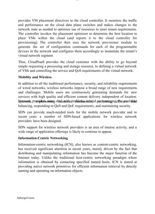
Control Plane Functions
Figure 5.2 illustrates the functions performed by SDN controllers. The figure illustrates the
essential functions that any controller should provide, as suggested in a paper by Kreutz [
KREU15], which include the following:
Sabarigirivason k
37.
lOM
oAR cP
SD| 30016045
FIGURE5.2 SDN Control Plane Functions and Interfaces
Shortest path forwarding: Uses routing information collected from switches to establish
preferred routes.
Notification manager: Receives, processes, and forwards to an application events, such as
alarm notifications, security alarms, and state changes.
Security mechanisms: Provides isolation and security enforcement between applications and
services.
Topology manager: Builds and maintains switch interconnection topology information.
Statistics manager: Collects data on traffic through the switches.
Device manager: Configures switch parameters and attributes and manages flow tables.
The functionality provided by the SDN controller can be viewed as a network operating
system (NOS). As with a conventional OS, an NOS provides essential services, common
application programming interfaces (APIs), and an abstraction of lower-layer elements to
developers. The functions of an SDN NOS, such as those in the preceding list, enable developers
to define network policies and manage networks without concern for the details of the network
device characteristics, which may be heterogeneous and dynamic. The northbound interface,
discussed subsequently, provides a uniform means for application developers and network
managers to access SDN service and perform network management tasks. Further, well-defined
northbound interfaces enable developers to create software that is independent not only of data
plane details but to a great extent usable with a variety of SDN controller servers.
A number of different initiatives, both commercial and open source, have resulted in
SDN controller implementations. The following list describes a few prominent ones:
OpenDaylight: An open source platform for network programmability to enable
SDN, written
Sabarigirivason k
38.
lOM
oAR cP
SD| 30016045
inJava. OpenDaylight was founded by Cisco and IBM, and its membership is heavily weighted
toward network vendors. OpenDaylight can be implemented as a single centralized controller, but
enables controllers to be distributed where one or multiple instances may run on one or more
clustered servers in the network.
Open Network Operating System (ONOS): An open source SDN NOS, initially released in
2014. It is a nonprofit effort funded and developed by a number of carriers, such as AT&T and
NTT, and other service providers. Significantly, ONOS is supported by the Open Networking
Foundation, making it likely that ONOS will be a major factor in SDN deployment. ONOS is
designed to be used as a distributed controller and provides abstractions for partitioning and
distributing network state onto multiple distributed controllers.
POX: An open source OpenFlow controller that has been implemented by a number of SDN
developers and engineers. POX has a well written API and documentation. It also provides a
web-based graphical user interface (GUI) and is written in Python, which typically shortens its
experimental and developmental cycles compared to some other implementation languages, such
as C++.
Beacon: An open source package developed at Stanford. Written in Java and highly
integrated
into the Eclipse integrated development environment (IDE). Beacon was the first controller that
made it possible for beginner programmers to work with and create a working SDN environment.
Floodlight: An open source package developed by Big Switch Networks. Although its
beginning was based on Beacon, it was built using Apache Ant, which is a very popular
software build tool that makes the development of Floodlight easier and more flexible. Floodlight
has an active community and has a large number of features that can be added to create a system
that best meets the requirements of a specific organization. Both a web-based and Java-based
GUI are available and most of its functionality is exposed through a REST API.
Ryu: An open source component-based SDN framework developed by NTT Labs. It is open
sourced and fully developed in python.
Onix: Another distributed controller, jointly developed by VMWare, Google, and NTT. Onix is
a commercially available SDN controller.
Southbound Interface
The southbound interface provides the logical connection between the SDN controller and the
data plane switches (see Figure 5.3). Some controller products and configurations support only a
single southbound protocol. A more flexible approach is the use of a southbound abstraction
layer that provides a common interface for the control plane functions while supporting multiple
southbound APIs.
Sabarigirivason k
39.
lOM
oAR cP
SD| 30016045
FIGURE5.3 SDN Controller Interfaces
The most commonly implemented southbound API is OpenFlow, covered in some detail in
Chapter 4, “SDN Data Plane and OpenFlow.” Other southbound interfaces include the
following:
Open vSwitch Database Management Protocol (OVSDB): Open vSwitch (OVS) an open
source software project which implements virtual switching that is interoperable with almost all
popular hypervisors. OVS uses OpenFlow for message forwarding in the control plane for both
virtual and physical ports. OVSDB is the protocol used to manage and configure OVS
instances.
Forwarding and Control Element Separation (ForCES): An IETF effort that standardizes
the interface between the control plane and the data plane for IP routers.
Protocol Oblivious Forwarding (POF): This is advertised as an enhancement to OpenFlow
that simplifies the logic in the data plane to a very generic forwarding element that need not
Sabarigirivason k
40.
Sabarigirivason k
lOM
oAR cP
SD|30016045
understand the protocol data unit (PDU) format in terms of fields at various protocol levels.
Rather, matching is done by means of (offset, length) blocks within a packet. Intelligence about
packet format resides at the control plane level.
Northbound Interface
The northbound interface enables applications to access control plane functions and services
without needing to know the details of the underlying network switches. The northbound
interface is more typically viewed as a software API rather than a protocol.
Unlike the southbound and eastbound/westbound interfaces, where a number of heterogeneous
interfaces have been defined, there is no widely accepted standard for the northbound interface.
The result has been that a number of unique APIs have been developed for various controllers,
complicating the effort to develop SDN applications. To address this issue the Open Networking
Foundation formed the Northbound Interface Working Group (NBI-WG) in 2013, with the
objective of defining and standardizing a number of broadly useful northbound APIs. As of this
writing, the working group has not issued any standards.
A useful insight of the NBI-WG is that even in an individual SDN controller instance, APIs are
needed at different “latitudes.” That is, some APIs may be “further north” than others, and access
to one, several, or all of these different APIs could be a requirement for a given application.
Figure 5.4, from the NBI-WG charter document (October 2013), illustrates the concept of
multiple API latitudes. For example, an application may need one or more APIs that
directly
expose the functionality of the controller, to manage a network domain, and use APIs that invoke
analytic or reporting services residing on the controller.
41.
lOM
oAR cP
SD| 30016045
FIGURE5.4 Latitude of Northbound Interfaces
Figure 5.5 shows a simplified example of an architecture with multiple levels of northbound
APIs, the levels of which are described in the list that follows.
Sabarigirivason k
42.
lOM
oAR cP
SD| 30016045
FIGURE5.5 SDN Controller APIs
Base controller function APIs: These APIs expose the basic functions of the controller and
are used by developers to create network services.
Network service APIs: These APIs expose network services to the north.
Northbound interface application APIs: These APIs expose application-related services that
are built on top of network services.
Sabarigirivason k
43.
lOM
oARcPSD|300 160 4
5
lOMo
ARcPS
D|300160 4
5
UNIT III : SDN APPLICATIONS
SDN Application Plane Architecture – Network Services Abstraction Layer –
Traffic Engineering – Measurement and Monitoring – Security – Data Center
Networking.
SDN Application Plane Architecture
The application plane contains applications and services that define, monitor, and
control network resources and behavior. These applications interact with the SDN
control plane via application-control interfaces, for the SDN control layer to
automatically customize the behavior and the properties of network resources. The
programming of an SDN application makes use of the abstracted view of network
resources provided by the SDN control layer by means of information and data
models exposed via the application-control interface.
SDN Application Plane Functions and Interfaces
Northbound Interface
“SDN Control Plane,” the northbound interface enables applications to access
control plane functions and services without needing to know the details of the
underlying network switches. Typically, the northbound interface provides an
abstract view of network resources controlled by the software in the SDN control
plane.
Sabarigirivason
44.
Sabarigirivason
lOM
oARcPSD|300 160 4
5
Fora local interface, the SDN applications are running on the same server as the
control plane software (controller network operating system). Alternatively, the
applications could be run on remote systems and the northbound interface is a
protocol or application programming interface (API) that connects the applications
to the controller network operating system (NOS) running on central server. Both
architectures are likely to be implemented.
Network Services Abstraction Layer
RFC 7426 defines a network services abstraction layer between the control and
application planes and describes it as a layer that provides service abstractions that
can be used by applications and services.
This layer could provide an abstract view of network resources that hides the
details of the underlying data plane devices.
This layer could provide a generalized view of control plane functionality, so that
applications could be written that would operate across a range of controller
network operating systems.
This functionality is similar to that of a hypervisor or virtual machine monitor
that decouples applications from the underlying OS and underlying hardware.
This layer could provide a network virtualization capability that allows different
views of the underlying data plane infrastructure.
Network Applications
There are many network applications that could be implemented for an
SDN. Different published surveys of SDN have come up with different lists
and even different general categories of SDN-based network applications.
User Interface
The user interface enables a user to configure parameters in SDN applications
and to interact with applications that support user interaction.
Network Services Abstraction Layer
An abstraction layer is a mechanism that translates a high-level request into
the low-level commands required to perform the request. An API is one
such mechanism. It shields the implementation details of a lower level of
abstraction from software at a higher level. A network abstraction represents the
basic
45.
lOM
oARcPSD|300 160 4
5
propertiesor characteristics of network entities (such as switches, links, ports, and
flows) is such a way that network programs can focus on the desired functionality
without having to program the detailed actions.
Abstractions in SDN
SDN Architecture and Abstractions
Forwarding Abstraction
The forwarding abstraction allows a control program to specify data plane
forwarding behavior while hiding details of the underlying switching hardware.
This abstraction supports the data plane forwarding function. By abstracting away
from the forwarding hardware, it provides flexibility and vender neutrality.
Distribution Abstraction
This abstraction arises in the context of distributed controllers. A cooperating set
of distributed controllers maintains a state description of the network and
routes through the networks. The distributed state of the entire network may
involve partitioned data sets, with controller instances exchanging routing
information, or a replicated data set, so that the controllers must cooperate to
maintain a consistent view of the global network.
Sabarigirivason
46.
Sabarigirivason
lOM
oARcPSD|300 160 4
5
Thisabstraction aims at hiding complex distributed mechanisms (used today in
many networks) and separating state management from protocol design and
implementation. It allows providing a single coherent global view of the network
through an annotated network graph accessible for control via an API. An
implementation of such an abstraction is an NOS, such as OpenDaylight or Ryu.
Specification Abstraction
The distribution abstraction provides a global view of the network as if there is a
single central controller, even if multiple cooperating controllers are used. The
specification abstraction then provides an abstract view of the global network. This
view provides just enough detail for the application to specify goals, such as
routing or security policy, without providing the information needed to implement
the goals.
Forwarding interface: An abstract forwarding model that shields higher layers
from forwarding hardware.
Distribution interface: A global network view that shields higher layers from
state dissemination/collection.
Specification interface: An abstract network view that shields application
program from details of physical network.
The physical network is a collection of interconnected SDN data plane
switches. The abstract view is a single virtual switch. The physical network may
consist of a single SDN domain. Ports on edge switches that connect to other
domains and to hosts are mapped into ports on the virtual switch. At the
application level, a module can be executed to learn the media access control
(MAC) address of hosts. When a previously unknown host sends a packet, the
application module can associate that address with the input port and direct this
host to this port. Similarly, if a packet arrives at one of the virtual switch ports
with an unknown destination address, the module floods that packet to all
output ports. The abstraction layer translates these actions on the entire
physical network, performing the internal forwarding with the domain.
47.
lOM
oARcPSD|300 160 4
5
Virtualizationof a Switching Fabric for MAC Learning
Frenetic
An example of a network services abstraction layer is the programming language
Frenetic. Frenetic enables networks operators to program the network as a whole
instead of manually configuring individual network elements. Frenetic was
designed to solve challenges with the use of OpenFlow-based models by working
with an abstraction at the network level as opposed to OpenFlow, which directly
goes down to the network element level.
Frenetic includes an embedded query language that provides effective abstractions
for reading network state. This language is similar to SQL and includes segments
for selecting, filtering, splitting, merging and aggregating the streams of packets.
Another special feature of this language is that it enables the queries to be
composed with forwarding policies. A compiler produces the control messages
needed to query and tabulate the counters on switches.
Frenetic consists of two levels of abstraction. The upper level, which is the
Frenetic source-level API, provides a set of operators for manipulating streams of
network traffic. The query language provides means for reading the state of the
network, merging different queries, and expressing high-level predicates for
classifying, filtering, transforming, and aggregating the packet streams traversing
the network. The lower level of abstraction is provided by a run-time system that
Sabarigirivason
48.
lOM
oARcPSD|300 160 4
5
operatesin the SDN controller. It translates high-level policies and queries into
low-level flow rules and then issues the needed OpenFlow commands to install
these rules on the switches.
Frenetic Architecture
The program combines forwarding functionality with monitoring web traffic
functionality. Consider the following Python program, which executes at the run-
time level, to control OpenFlow switches:
def switch_join(s):
pat1 = {inport:1}
pat2web = {inport:2, srcport:80}
pat2 = {inport:2}
install(s, pat1, DEFAULT,
[fwd(2)])
install(s, pat2web, HIGH, [fwd(1)])
install(s, pat2, DEFAULT, [fwd(1)])
query_stats(s, pat2web)
def stats_in(s, xid, pat, pkts,
bytes): print bytes
sleep(30)
query_stats(s, pat)
When a switch joins
the network, the
program installs
three forwarding
rules in the
switch for three types of traffic: traffic arriving on port 1, web traffic arriving on
port 2, and other traffic arriving on port 2. The second rule has HIGH priority and
so takes precedence over the third rule, which has default priority. The call to
query_stats generates a request for the counters associated with the pat2web rule.
Sabarigirivason
49.
Sabarigirivason
lOM
oARcPSD|300 160 4
5
Whenthe controller receives the reply, it invokes the stats_in handler. This
function prints the statistics polled on the previous iteration of the loop, waits 30
seconds, and then issues a request to the switch for statistics matching the same
rule.
With Frenetic, these two functions can be expressed separately, as follows:
def repeater():
rules=[Rule(inport:1, [fwd(2)])
Rule(inport:2, [fwd(1)])]
register(rules)
def web monitor():
q = (Select(bytes) *
Where(inport=2 & srcport=80) *
Every(30))
q >> Print()
def main():
repeate
r()
monitor()
With this code, it would be easy to change the monitor program or swap it out
for another monitor program without touching the repeater code, and similarly for
the changes to the repeater program.
Traffic Engineering
Traffic engineering is a method for dynamically analyzing, regulating,
and predicting the behavior of data flowing in networks with the aim of
performance optimization to meet service level agreements (SLAs). Traffic
engineering involves establishing routing and forwarding policies based on
QoS requirements. With SDN, the task of traffic engineering should be
considerably simplified compared with a non-SDN network. SDN offers a
uniform global view of heterogeneous equipment and powerful tools for
configuring and managing network switches.
• On-demand virtual private networks
• Load balancing
• Energy-aware routing
• Quality of service (QoS) for broadband access networks
• Scheduling/optimization
• Traffic engineering with minimal overhead
50.
lOM
oARcPSD|300 160 4
5
•Dynamic QoS routing for multimedia apps
• Fast recovery through fast-failover groups
• QoS policy management framework
• QoS enforcement
• QoS over heterogeneous networks
• Multiple packet schedulers
• Queue management for QoS enforcement
• Divide and spread forwarding tables
PolicyCop
• Dynamic traffic steering
• Flexible Flow level control
• Dynamic traffic classes
• Custom flow aggregation levels
Key features of PolicyCop are that it monitors the network to detect policy
violations (based on a QoS SLA) and reconfigures the network to reinforce the
violated policy.PolicyCop consists of eleven software modules and two databases,
installed in both the application plane and the control plane. PolicyCop uses the
control plane of SDNs to monitor the compliance with QoS policies and can
automatically adjust the control plane rules and flow tables in the data plane based
on the dynamic network traffic statistics.
PolicyCop Architecture
Sabarigirivason
51.
Sabarigirivason
lOM
oARcPSD|300 160 4
5
Inthe control plane, PolicyCop relies on four modules and a database for storing
control rules, described as follows:
Admission Control: Accepts or rejects requests from the resource provisioning
module for reserving network resources, such as queues, flow-table entries, and
capacity.
Routing: Determines path availability based on the control rules in the rule
database.
Device Tracker: Tracks the up/down status of network switches and their ports.
Statistics Collection: Uses a mix of passive and active monitoring techniques to
measure different network metrics.
Rule Database: The application plane translates high-level network-wide policies
to control rules and stores them in the rule database.
A RESTful northbound interface connects these control plane modules to
the application plane modules, which are organized into two components: a
policy validator that monitors the network to detect policy violations, and a
policy enforcer that adapts control plane rules based on network conditions and
high-level policies. Both modules rely on a policy database, which contains QoS
policy rules entered by a network manager. The modules are as follows:
Traffic Monitor: Collects the active policies from policy database, and
determines appropriate monitoring interval, network segments, and metrics to be
monitored.
Policy Checker: Checks for policy violations, using input from the policy
database and the Traffic Monitor.
Event Handler: Examines violation events and, depending on event type, either
automatically invokes the policy enforcer or sends an action request to the
network manager.
Topology Manager: Maintains a global view of the network, based on input from
the device tracker.
Resource Manager: Keeps track of currently allocated resources using admission
control and statistics collection.
52.
lOM
oARcPSD|300 160 4
5
PolicyAdaptation: Consists of a set of actions, one for each type of policy
violation.
TABLE Functionality of Some Example Policy Adaptation Actions (PAAs)
Resource Provisioning: This module either allocates more resources or releases
existing ones or both based on the violation event.
PolicyCop Workflow
Sabarigirivason
53.
Sabarigirivason
lOM
oARcPSD|300 160 4
5
Measurementand Monitoring
The area of measurement and monitoring applications can roughly be divided into
two categories: applications that provide new functionality for other networking
services, and applications that add value to OpenFlow-based SDNs.
An example of the first category is in the area of broadband home connections. If
the connection is to an SDN-based network, new functions can be added to the
measurement of home network traffic and demand, allowing the system to react to
changing conditions. The second category typically involves using different kinds
of sampling and estimation techniques to reduce the burden of the control plane in
the collection of data plane statistics.
Security
Applications in this area have one of two goals:
Address security concerns related to the use of SDN: SDN involves a three-layer
architecture (application, control, data) and new approaches to distributed control
and encapsulating data. All of this introduces the potential for new vectors for
attack. Threats can occur at any of the three layers or in the communication
between layers. SDN applications are needed to provide for the secure use of SDN
itself.
Use the functionality of SDN to improve network security: Although SDN
presents new security challenges for network designers and managers, it also
provides a platform for implementing consistent, centrally managed security
policies and mechanisms for the network. SDN allows the development of SDN
security controllers and SDN security applications that can provision and
orchestrate security services and mechanisms.
OpenDaylight DDoS Application
In 2014, Radware, a provider of application delivery and application
security solutions for virtual and cloud data centers, announced its
contribution to the OpenDaylight Project with Defense4All, an open SDN
security application integrated into OpenDaylight. Defense4All offers carriers
and cloud providers distributed denial of service (DDoS) detection and
mitigation as a native network service. Using the OpenDaylight SDN
Controller that programs SDN-enabled networks to become part of the
DoS/DDoS protection service itself, Defense4All
54.
lOM
oARcPSD|300 160 4
5
enablesoperators to provision a DoS/DDoS protection service per virtual network
segment or per customer.
Defense4All uses a common technique for defending against DDoS attacks, which
consists of the following elements:
Collection of traffic statistics and learning of statistics behavior of protected
objects during peacetime. The normal traffic baselines of the protected objects are
built from these collected statistics.
Detection of DDoS attack patterns as traffic anomalies deviating from normal
baselines.
Diversion of suspicious traffic from its normal path to attack mitigation systems
(AMSs) for traffic scrubbing, selective source blockage, and so on. Clean traffic
exiting out of scrubbing centers is re-injected back into the packet’s original
destination.
The underlying SDN network consists of a number of data plane switches
that support traffic among client and server devices. Defense4All operates
as an application that interacts with the controller over an OpenDaylight
controller (ODC) northbound API. Defense4All supports a user interface
for network managers that can either be a command line interface or a RESTful
API. Finally, Defense4All has an API to communicate with one or more AMSs.
OpenDaylight DDoS Application
Sabarigirivason
55.
Sabarigirivason
lOM
oARcPSD|300 160 4
5
Administratorscan configure Defense4All to protect certain networks and servers,
known as protected networks (PNs) and protected objects (POs). The application
instructs the controller to install traffic counting flows for each protocol of each
configured PO in every network location through which traffic of the subject PO
flows.
Defense4All then monitors traffic of all configured POs, summarizing readings,
rates, and averages from all relevant network locations. If it detects a deviation
from normal learned traffic behavior in a protocol (such as TCP, UDP, ICMP, or
the rest of the traffic) of a particular PO, Defense4All declares an attack against
that protocol in the subject PO. Specifically, Defese4All continuously calculates
traffic averages for real time traffic it measured using OpenFlow; when real time
traffic deviates by 80% from average then an attack is assumed.
To mitigate a detected attack, Defense4All performs the following procedure:
1.It validates that the AMS device is alive and selects a live connection to
it. Currently, Defense4All is configured to work with Radware’s AMS, known
as DefensePro.
2.It configures the AMS with a security policy and normal rates of the
attacked traffic. This provides the AMS with the information needed to enforce a
mitigation policy until traffic returns to normal rates.
3.It starts monitoring and logging syslogs arriving from the AMS for the
subject traffic. As long as Defense4All continues receiving syslog attack
notifications from the AMS regarding this attack, Defense4All continues to divert
traffic to the AMS, even if the flow counters for this PO do not indicate any more
attacks.
4.It maps the selected physical AMS connection to the relevant PO link.
This typically involves changing link definitions on a virtual network, using
OpenFlow.
5.It installs higher-priority flow table entries so that the attack traffic flow
is redirected to the AMS and re-injects traffic from the AMS back to the
normal traffic flow route. When Defense4All decides that the attack is over
(no attack indication from either flow table counters or from the AMS), it reverts
the previous actions: It stops monitoring for syslogs about the subject traffic, it
removes the traffic diversion flow table entries, and it removes the security
configuration from the AMS. Defense4All then returns to peacetime monitoring.
Sabarigirivason
lOM
oARcPSD|300 160 4
5
Web(REST) Server: Interface to network manager.
Framework Main: Mechanism to start, stop, or reset the framework.
Framework REST Service: Responds to user requests received through the web
(REST) server.
Framework Management Point: Coordinates and invokes control and
configuration commands.
Defense4All Application: Described subsequently.
Common Classes and Utilities: A library of convenient classes and utilities from
which any framework or SDN application module can benefit.
Repository Services: One of the key elements in the framework philosophy is
decoupling the compute state from the compute logic. All durable states are stored
in a set of repositories that can be then replicated, cached, and distributed, with no
awareness of the compute logic (framework or application).
Logging and Flight Recorder Services: The logging service uses logs error,
warning, trace, or informational messages. These logs are mainly for Defense4All
developers. The Flight Recorder records events and metrics during run time from
Java applications.
Health Tracker: Holds aggregated run-time indicators of the operational health of
Defense4All and acts in response to severe functional or performance
deteriorations.
Cluster Manager: Responsible for managing coordination with other Defense4All
entities operating in a cluster mode.
The Defense4All Application module consists of the following
elements. DF App Root: The root module of the application.
DF Rest Service: Responds to Defense4All application REST requests.
DF Management Point: The point to drive control and configuration commands.
DFMgmtPoint in turn invokes methods against other relevant modules in the right
order.
58.
Sabarigirivason
lOM
oARcPSD|300 160 4
5
ODLReps: A pluggable module set for different versions of the ODC. Comprises
two functions in two submodules: stats collection for and traffic diversion of
relevant traffic.
SDN Stats Collector: Responsible for setting “counters” for every PN at specified
network locations (physical or logical). A counter is a set of OpenFlow flow entries
in ODC-enabled network switches and routers. The module periodically collects
statistics from those counters and feeds them to the SDNBasedDetectionMgr. The
module uses the SDNStatsCollectionRep to both set the counters and read latest
statistics from those counters. A stat report consists of read time, counter
specification, PN label, and a list of trafficData information, where each trafficData
element contains the latest bytes and packet values for flow entries configured for
<protocol,port,direction> in the counter location. The protocol can be
{tcp,udp,icmp,other ip}, the port is any Layer 4 port, and the direction can
be
{inbound, outbound}.
SDN Based Detection Manager: A container for pluggable SDN-based detectors.
It feeds stat reports received from the SDNStatsCollector to plugged-in SDN based
detectors. It also feeds all SDN based detectors notifications from the
AttackDecisionPoint about ended attacks (so as to allow reset of detection
mechanisms). Each detector learns for each PN its normal traffic behavior over
time, and notifies AttackDecisionPoint when it detects traffic anomalies.
Attack Decision Point: Responsible for maintaining attack lifecycle, from
declaring a new attack, to terminating diversion when an attack is considered over.
Mitigation Manager: A container for pluggable mitigation drivers. It maintains the
lifecycle of each mitigation being executed by an AMS. Each mitigation driver is
responsible for driving attack mitigations using AMSs in their sphere of
management.
AMS Based Detector: This module is responsible for monitoring/querying attack
mitigation by AMSs.
AMS Rep: Controls the interface to AMSs.
Finally, it is worth noting that Radware has developed a commercial version
of Defese4All, named DefenseFlow. DefenseFlow implements more
sophisticated algorithms for attack detection based on fuzzy logic. The main
benefit is that DefenseFlow has a greater ability to distinguish attack traffic
from abnormal but legitimate high volume of traffic.
59.
Sabarigirivason
lOM
oARcPSD|300 160 4
5
DataCenter Networking
So far we’ve discussed three areas of SDN applications: traffic engineering,
measurement and monitoring, and security. The provided examples of these
applications suggest the broad range of use cases for them, in many different kinds
of networks. The remaining three applications areas (data center networking,
mobility and wireless, and information-centric networking) have use cases in
specific types of networks.
Cloud computing, big data, large enterprise networks, and even in many cases,
smaller enterprise networks, depend strongly on highly scalable and efficient data
centers. [KREU15] lists the following as key requirements for data centers: high
and flexible cross-section bandwidth and low latency, QoS based on the
application requirements, high levels of resilience, intelligent resource utilization
to reduce energy consumption and improve overall efficiency, and agility in
provisioning network resources (for example, by means of network virtualization
and orchestration with computing and storage).
With traditional network architectures, many of these requirements are difficult to
satisfy because of the complexity and inflexibility of the network. SDN offers the
promise of substantial improvement in the ability to rapidly modify data center
network configurations, to flexibly respond to user needs, and to ensure efficient
operation of the network.
The remainder of this subsection, examines two example data center SDN
applications.
Big Data over SDN
The approach leverages the capabilities of SDN to provide application-aware
networking. It also exploits characteristics of structured big data applications as
well as recent trends in dynamically reconfigurable optical circuits. With respect
to structured big data applications, many of these applications process data
according to well-defined computation patterns, and also have a centralized
management structure that makes it possible to leverage application-level
information to optimize the network. That is, knowing the anticipated
computation patterns of the big data application, it is possible to intelligently
deploy the data across the big
60.
lOM
oARcPSD|300 160 4
5
dataservers and, more significantly, react to changing application patterns by
using SDN to reconfigure flows in the network.
Compared to electronic switches, optical switches have the advantages of greater
data rates with reduced cabling complexity and energy consumption. A number of
projects have demonstrated how to collect network-level traffic data and
intelligently allocate optical circuits between endpoints (for example, top-of-rack
switches) to improve application performance. However, circuit utilization and
application performance can be inadequate unless there is a true application-level
view of traffic demands and dependencies. Combining an understanding of the big
data computation patterns with the dynamic capabilities of SDN, efficient data
center networking configurations can be used to support the increasing big data
demands.
A simple hybrid electrical and optical data center network, in which OpenFlow-
enabled top-of-rack (ToR) switches are connected to two aggregation switches: an
Ethernet switch and an optical circuit switch (OCS). All the switches are
controlled by a SDN controller that manages physical connectivity among ToR
switches over optical circuits by configuring the optical switch. It can also
manage the forwarding at ToR switches using OpenFlow rules.
Integrated Network Control for Big Data Applications
The SDN controller is also connected to the Hadoop scheduler, which forms
queues of jobs to be scheduled and the HBase primary controller of a relational
database holding data for the big data applications. In addition, the SDN controller
connects to a Mesos cluster manager. Mesos is an open source software package
Sabarigirivason
61.
lOM
oARcPSD|300 160 4
5
thatprovides scheduling and resource allocation services across distributed
applications.
The SDN controller makes available network topology and traffic information to
the Mesos cluster manager. In turn, the SDN controller accepts traffic demand
request from Mesos managers.
Cloud Networking over SDN
Cloud Network as a Service (CloudNaaS) is a cloud networking system that
exploits OpenFlow SDN capabilities to provide a greater degree of control over
cloud network functions by the cloud customer [BENS11]. CloudNaaS enables
users to deploy applications that include a number of network functions, such as
virtual network isolation, custom addressing, service differentiation, and flexible
interposition of various middleboxes. CloudNaaS primitives are directly
implemented within the cloud infrastructure itself using high-speed programmable
network elements, making CloudNaaS highly efficient.
Various Steps in the CloudNaaS Framework
Sabarigirivason
62.
Sabarigirivason
lOM
oARcPSD|300 160 4
5
a.Acloud customer uses a simple policy language to specify network
services required by the customer applications. These policy statements are
issued to a cloud controller server operated by the cloud service provider.
b.The cloud controller maps the network policy into a communication matrix
that defines desired communication patterns and network services. The matrix is
used to determine the optimal placement of virtual machines (VMs) on cloud
servers such that the cloud can satisfy the largest number of global policies in an
efficient manner. This is done based on the knowledge of other customers’
requirements and their current levels of activity.
c.The logical communication matrix is translated into network-level directives
for data plane forwarding elements. The customer’s VM instances are deployed
by creating and placing the specified number of VMs.
d.The network-level directives are installed into the network devices
via OpenFlow.
The abstract network model seen by the customer consists of VMs and virtual
network segments that connect VMs together. Policy language constructs identify
the set of VMs that comprise an application and define various functions and
capabilities attached to virtual network segments. The main constructs are as
follows:
address: Specify a customer-visible custom address for a VM.
group: Create a logical group of one or more VMs. Grouping VMs with similar
functions makes it possible for modifications to apply across the entire group
without requiring changing the service attached to individual VMs.
middlebox: Name and initialize a new virtual middlebox by specifying its type
and a configuration file. The list of available middleboxes and their
configuration syntax is supplied by the cloud provider. Examples include intrusion
detection and audit compliance systems.
Network service: Specify capabilities to attach to a virtual network segment, such
as Layer 2 broadcast domain, link QoS, and list of middleboxes that must be
traversed.
virtualnet: Virtual network segments connect groups of VMs and are associated
with network services. A virtual network can span one or two groups. With a
single group, the service applies to traffic between all pairs of VMs in the group.
With a
63.
lOM
oARcPSD|300 160 4
5
pairof groups, the service is applied between any VM in the first group and any
VM in the second group. Virtual networks can also connect to some predefined
groups, such as EXTERNAL, which indicates all endpoints outside of the cloud.
Its two main components are a cloud controller and a network controller. The
cloud controller provides a base Infrastructure as a Service (IaaS) service for
managing VM instances. The user can communicate standard IaaS requests, such
as setting up VMs and storage. In addition, the network policy constructs enable
the user to define the virtual network capabilities for the VMs. The cloud
controller manages a software programmable virtual switch on each physical
server in the cloud that supports network services for tenant applications,
including the management of the user-defined virtual network segments. The
cloud controller constructs the communication matrix and transmits this to the
network controller.
CloudNaaS Architecture
The network controller uses the communication matrix to configure data plane
physical and virtual switches. It generates virtual networks between VMs and
Sabarigirivason
64.
Sabarigirivason
lOM
oARcPSD|300 160 4
5
providesVM placement directives to the cloud controller. It monitors the traffic
and performance on the cloud data plane switches and makes changes to the
network state as needed to optimize use of resources to meet tenant requirements.
The controller invokes the placement optimizer to determine the best location to
place VMs within the cloud (and reports it to the cloud controller for
provisioning). The controller then uses the network provisioner module to
generate the set of configuration commands for each of the programmable
devices in the network and configures them accordingly to instantiate the tenant’s
virtual network segment.
Thus, CloudNaaS provides the cloud customer with the ability to go beyond
simple requesting a processing and storage resource, to defining a virtual network
of VMs and controlling the service and QoS requirements of the virtual network.
Mobility and Wireless
In addition to all the traditional performance, security, and reliability requirements
of wired networks, wireless networks impose a broad range of new requirements
and challenges. Mobile users are continuously generating demands for new
services with high quality and efficient content delivery independent of location.
Network providers must deal with problems related to managing the available
spectrum, implementing handover mechanisms, performing efficient load
balancing, responding to QoS and QoE requirements, and maintaining security.
SDN can provide much-needed tools for the mobile network provider and in
recent years a number of SDN-based applications for wireless network
providers have been designed.
SDN support for wireless network providers is an area of intense activity, and a
wide range of application offerings is likely to continue to appear.
Information-Centric Networking
Information-centric networking (ICN), also known as content-centric networking,
has received significant attention in recent years, mainly driven by the fact that
distributing and manipulating information has become the major function of the
Internet today. Unlike the traditional host-centric networking paradigm where
information is obtained by contacting specified named hosts, ICN is aimed at
providing native network primitives for efficient information retrieval by directly
naming and operating on information objects.
65.
Sabarigirivason
lOM
oARcPSD|300 160 4
5
WithICN, a distinction exists between location and identity, thus decoupling
information for its sources. The essence of this approach is that information
sources can place, and information users can find, information anywhere in the
network, because the information is named, addressed, and matched independently
of its location. In ICN, instead of specifying a source-destination host pair for
communication, a piece of information itself is named. In ICN, after a request is
sent, the network is responsible for locating the best source that can provide the
desired information. Routing of information requests thus seeks to find the best
source for the information, based on a location-independent name.
Deploying ICN on traditional networks is challenging, because existing routing
equipment would need to be updated or replace with ICN-enabled routing devices.
Further, ICN shifts the delivery model from host to user to content to user. This
creates a need for a clear separation between the task of information demand and
supply, and the task of forwarding. SDN has the potential to provide the necessary
technology for deploying ICN because it provides for programmability of the
forwarding elements and a separation of control and data planes.
A number of projects have proposed using SDN capabilities to implement ICNs.
There is no consensus approach to achieving this coupling of SDN and ICN.
Suggested approaches include substantial enhancements/modifications to the
OpenFlow protocol, developing a mapping of names into IP addresses using a
hash function, using the IP option header as a name field, and using an abstraction
layer between an OpenFlow (OF) switch and an ICN router, so that the layer, OF
switch, and ICN router function as a single programmable ICN router.
The approach is built on an open protocol specification and a software reference
implementation of ICN known as CCNx.
CCNx
CCNx is being developed by the Palo Alto Research Center (PARC) as an open
source project, and a number of implementations have been experimentally
deployed.
CCNx
Communication in CCN is via two packet types: Interest packets and Content
packets. A consumer requests content by sending an Interest packet. Any CCN
node that receives the Interest and has named data that satisfies the Interest
responds with a Content packet (also known as a Content). Content satisfies an
66.
Sabarigirivason
lOM
oARcPSD|300 160 4
5
Interestif the name in the Interest packet matches the name in the Content Object
packet. If a CCN node receives an Interest, and does not already have a copy of the
requested Content, it may forward the Interest toward a source for the content. The
CCN node has forwarding tables that determine which direction to send the
Interest. A provider receiving an Interest for which it has matching named content
replies with a Content packet. Any intermediate node can optionally choose to
cache the Content Object, and it can respond with a cached copy of the Content
Object the next time it receives an Interest packet with the same name.
The basic operation of a CCN node is similar to an IP node. CCN nodes receive
and send packets over faces. A face is a connection point to an application, or
another CCN node, or some other kind of channel. A face may have attributes that
indicate expected latency and bandwidth, broadcast or multicast capability, or
other useful features. A CCN node has three main data structures:
Content Store: Holds a table of previously seen (and optionally cached) Content
packets.
Forwarding Information Base (FIB): Used to forward Interest packets toward
potential data sources.
Pending Interest Table (PIT): Used to keep track of Interests forwarded upstream
by that CCN node toward the content source so that Content packets later received
can be sent back to their requestors.
The details of how content sources become known and how routes are set
up through the CCN network are beyond our scope. Briefly, content
providers advertise names of content and routes are established through the CCN
network by cooperation among the CCN nodes.
ICN relies substantially on in-network caching—that is, to cache content on
the path from content providers to requesters. This on-path caching achieves
good overall performance but is not optimal as content may be replicated on
routers, thus reducing the total volume of content that can be cached. To
overcome this limitation, off-path caching can be used, which allocates content
to well-defined off-path caches within the network and deflects the traffic off
the optimal path toward these caches that are spread across the network. Off-path
caching improves the global hit ratio by efficiently utilizing the network-wide
available caching capacity and permits to reduce egress links’ bandwidth usage.
Use of an Abstraction Layer
67.
lOM
oARcPSD|300 160 4
5
Thecentral design issue with using an SDN switch (in particular an OF switch) to
function as an ICN router is that the OF switch forwards on the basis of fields in
the IP packet, especially the destination IP address, and an ICN router forwards on
the basis of a content name. In essence, the proposed approach hashes the name
inside the fields with an OF switch can process.
To link a CCNx node software module with an OF switch, an abstraction layer,
called the wrapper, is used. The wrapper pairs a switch interface to a CCNx face,
decodes and hashes content names in CCN messages into fields that an OF switch
can process (for example, IP addresses, port numbers). The large naming space
offered by these fields limits the probability of having collisions between two
different content names. The forwarding tables in the OF switch are set to forward
based on the contents of the hashed fields. The switch does not “know” that the
contents of these fields are no longer legitimate IP addresses, TCP port numbers,
and so forth. It forwards as always, based on the values found in the relevant fields
of incoming IP packets.
Sabarigirivason
68.
Sabarigirivason
lOM
oARcPSD|300 160 4
5
ICNWrapper Approach
The abstraction layer solves the problem of how to provide CCN functionality
using current OF switches. For efficient operation, two additional challenges need
to be addressed: how to measure the popularity of content accurately and without a
large overhead, and how to build and optimize routing tables to perform
deflection. To address these issues, the architecture calls for three new modules
in the SDN controller:
Measurement: Content popularity can be inferred directly from OF flow statistics.
The measurement module periodically queries and processes statistics from ingress
OF switches to return the list of most popular content.
Optimization: Uses the list of most popular contents as an input for the
optimization algorithm. The objective is to minimize the sum of the delays over
deflected contents under the following constraints: (1) each popular content is
cached at exactly one node, (2) caching contents at a node does not exceed node’s
capacity, and (3) caching should not cause link congestion.
Deflection: Uses the optimization results to build a mapping, for every content,
between the content name (by means of addresses and ports computed from the
content name hash) and an outgoing interface toward the node where the content is
cached (for example, ip.destination = hash(content name), action = forward to
interface 1).
Finally, mappings are installed on switches’ flow tables using the OF protocol
such that subsequent Interest packets can be forwarded to appropriate caches.
The OpenFlow switch forwards every packet it receives from other ports to
the wrapper, and the wrapper forwards it to the CCNx module. The OpenFlow
switch needs to help the wrapper identify the switch source port of the packet. To
achieve this, the OF switch is configured to set the ToS value of all packets it
receives to the corresponding incoming port value and then forward all of
them to the wrapper’s port.
69.
lOM
oARcPSD|300 160 4
5
PacketFlow Between CCNx and OpenFlow Switch
The wrapper maps a face of CCNx to an interface (that is, port) of OpenFlow
switches using ToS value. Face W is a special face between wrapper and the
CCNx module. W receives every Content packet from the wrapper and is used
to send every Interest packet from CCNx to the wrapper.
For an Interest packet, the wrapper extracts the face value from the ToS field and
forwards the packet to the corresponding CCNx face. If the CCNx node holds a
copy of the requested content, it composes a Content packet and returns it back to
the incoming face. Otherwise, it forwards this Interest to face W and updates its
PIT accordingly. Upon Content packet arrival from the OF switch, the wrapper
forwards it directly to face W.
The operation of the wrapper on packets received from the CCNx module. For
content packets, it sets the ToS field accordingly, specifying the output port. Then,
for any packet, it decodes the packet to extract the content name related to the
packet. The name is hashed and the source IP address of the packet is set to
correspond to the hashed value. Finally, the wrapper forwards the packets to OF
switches. Content packets are returned to their corresponding incoming face.
Interest packets have the ToS value set to zero so they are forwarded to next hop
by the OF switch.
Sabarigirivason
K.SABARIGIRIVASON
lOM
oARcP
SD|300 160 4
5
18ECE320T- Software Defined Networks
UNIT 4
What is a Data Center?
A facility composed of networked computers, storage systems and computing infrastructure that
organizations use to assemble, process, store and disseminate large amounts of data.
How do data centers work?
A data center facility, which enables an organization to collect its resources and infrastructure for
data processing, storage and communications, includes the following:
● systems for storing, sharing, accessing and processing data across the organization;
● physical infrastructure for supporting data processing and data communications; and
● utilities such as cooling, electricity, network security access and uninterruptible power
supplies (UPSes).
Why are data centers important?
Data centers enable organizations to concentrate on the following:
● IT and data processing personnel;
● computing and network connectivity infrastructure;
● protect proprietary systems and data;
● centralize IT and data processing employees, contractors and vendors;
● apply information security controls to proprietary systems and data;
● realize economies of scale by consolidating sensitive systems in one place.
What are the core components of data centers?
Facility. This includes the physical location with security access controls and sufÏcient square footage
to house the data center's infrastructure and equipment.
Enterprise data storage. A modern data center houses an organization's data systems in a well-
protected physical and storage infrastructure along with servers, storage subsystems, networking
switches, routers, firewalls, cabling and physical racks.
Support infrastructure. This equipment provides the highest available sustainability related to
uptime. Components of the support infrastructure include power distribution and
supplemental
72.
K.SABARIGIRIVASON
lOM
oARcP
SD|300 160 4
5
powersubsystems;electrical switching;UPSes;backup generators;ventilation and data center cooling
systems, such as in-row cooling configurations and computer room air conditioners; and adequate
provisioning for network carrier, or telecom, connectivity.
Operational staff. These employees are required to maintain and monitor IT and infrastructure
equipment around the clock.
What are the types of data centers?
Enterprise data centers. These proprietary data centers are built and owned by organizations for
their internal end users. They support the IT operations and critical applications of a single
organization and can be located both on-site and off-site.
Managed services data centers. Managed by third parties, these data centers provide all aspects
of data storage and computing services. Companies lease, instead of buy, the infrastructure and
services.
Cloud-based data centers. These off-site distributed data centers are managed by third-party or
public cloud providers, such as Amazon Web Services, Microsoft Azure or Google Cloud. Based on
an infrastructure-as-a-service model, the leased infrastructure enables customers to provision a
virtual data center within minutes.
Colocation data centers. These rental spaces inside colocation facilities are owned by third parties.
The renting organization provides the hardware, and the data center provides and manages the
infrastructure, including physical space, bandwidth, cooling and security systems. Colocation is
appealing to organizations that want to avoid the large capital expenditures associated with building
and maintaining their own data centers.
Edge data centers. These are smaller facilities that solve the latency problem by being geographically
closer to the edge of the network and data sources.
Hyperscale data centers. Synonymous with large-scale providers, such as Amazon, Meta and Google,
these hyperscale computing infrastructures maximize hardware density, while minimizing the cost of
cooling and administrative overhead.
SDN in the Data Center
Data centers hold thousands, even tens of thousands, of physical servers. These data centers can be
segregated into the following three categories:
•Private single-tenant. Individual organizations that maintain their own data centers belong in
this category. The data center is for the private use of the organization, and there is only the one
organization or tenant using the data center.
•Private multitenant. Organizations that provide specialized data center services on behalf of
other client organizations belong in this category. IBM and EDS (now HP) are examples of
companies that host such data centers. These centers are built and maintained by the organization
providing the service, and multiple clients store data there, suggesting the term multitenant. These
data centers are private because they offer their services contractually to specific clients
73.
K.SABARIGIRIVASON
lOM
oARcP
SD|300 160 4
5
Publicmultitenant. Organizations that provide generalized data center services to any individual or
organization belong in this category. Examples of companies that provide these services include
Google and Amazon. These data centers offer their services to the public. Anybody, whether
individuals or organizations, who wants to use these services may access them via the web.
Cloud Data centres: Data centers accessible through the Internet. These types of data centers are
often referred to as residing in the cloud.
Public cloud: A service provider makes services available to the general public over the Internet.
Examples of public cloud offerings include Microsoft Azure Services Platform and Amazon Elastic
Compute Cloud.
Private cloud: A set of server and network resources is assigned to one tenant exclusively
and protected behind a firewall specific to that tenant. The physical resources of the cloud are
owned and maintained by the cloud provider, which may be a distinct entity from the tenant. The
physical infrastructure may be managed using a product such as VMware’s vCloud. Amazon Web
Services is an example of the way a private cloud may also be hosted by a third party (i.e., Amazon).
Hybrid Cloud: Part of the cloud runs on resources dedicated to a single tenant, but other parts
reside on resources that are shared with other tenants. The shared resources may be
acquired and released dynamically as demand grows and declines. Example is Verizon’s cloud
bursting
Data Center Demands
1.Overcoming Current Network Limitations
The dynamic nature and large number of VMs in the data center have placed demands on
the capacity of network components. In particular, these areas include
● MAC address table size explosion
● number of VLANs,
● spanning tree.
a. MAC Address Explosion:
In switches and routers, the device uses MAC address table to quickly determine the port or
interface out of which the device should forward the packet. For speed, this table is implemented in
hardware. As such, it has a physical limit to its size. Networks had manageable limits on the
maximum number of MAC addresses that would need to be in the MAC address table at any given
time. Layer two switches are designed to handle the case of a MAC table miss by flooding the
frame out all ports except the one on which it arrived, as shown in Figure. From the response from
the destination, the switch is able to learn the port on which that MAC address is located and
populates its MAC table accordingly. This scheme works well unless the MAC table is full, in which
case it cannot learn the address.
74.
lOM
oARcP
SD|300 160 4
5
b.Number of VLANs
When the IEEE 802.1 working group created the 802.1Q extension to the definition of local area
networks, they did not anticipate that there would be a need for more than 12 bits to hold potential
VLAN IDs. The IEEE 802.1Q tag for VLANs is shown in Figure . The tag depicted in Figure supports 212
(4096) VLANs.When data centers continued to expand, however, especially with multi-tenancy and
server virtualization,the number of VLANs required could easily exceed 4096.An upshot of the limit
of 4096 VLANs has been an increase in the use of MPLS since it does not have limitation on number
of MPLS tags. It is likely,, that MPLS will see more use in data centers
c. Spanning Tree
Bridges were built as transparent devices capable of forwarding packets from one segment to
another without explicit configuration of forwarding tables by an operator. The bridges learned
forwarding tables by observing the trafÏc being forwarded through them. They create a spanning
tree, which enforces a loop-free hierarchical structure on the network in situations where physical
loops do exist. This spanning tree was then calculated using the Spanning Tree Protocol (STP), The
process of determining this spanning tree is called convergence.The fluidity of data center
virtualization has increased the frequency of changes and disruptions, thus requiring reconvergence
to occur more often, adding to the inefÏciency of STP in the data center.Data centers need more
cross-sectional bandwidth i.e using the most efÏcient path between any two nodes without
imposing an artificial hierarchy in the trafÏc patterns.
K.SABARIGIRIVASON
75.
K.SABARIGIRIVASON
lOM
oARcP
SD|300 160 4
5
2.Adding,Moving, and Deleting Resources
Networks need to adapt in order to keep pace with the virtualization
capabilities of servers and storage. Speed and automation are of critical
importance when it comes to handling the rapid changes demanded by
virtualized servers and storage.These changes need to have the ability to be
automated so that changes that must happen immediately can take place
without human intervention.With SDN one can use the foreknowledge that a
new service is about to be initiated and proactively allocate the network
capacity it will require.
3.Failure Recovery
The size and scale of data centers today make recovery from failure a complex
task, and the ramifications of poor recovery decisions are only magnified as
scale grows. Determinism, predictability, and optimal re-configuration are
among the most important recovery-related considerations.
It is desirable that the network move to a known state, given a particular
failure. Distributed protocols make this difÏcult to do. A complete view of the
network as is provided by SDN is required to make the recovery process yield
the best result.
4. Multitenancy
Data center consolidation has resulted in more and more clients occupying the
same set of servers, storage, and network. The challenge is to keep those
individual clients separated and insulated from each other and to utilize
network bandwidth efÏciently.
In a large multitenant environment, it is necessary to keep separate the
resources belonging to each client. For servers this could mean not mixing
clients’ virtual machines on the same physical server.For networks it could
mean segregation of trafÏc using a technology that ensures that packets from
two distinct tenants remain insulated from one another. This is needed not
only for the obvious security reasons but also for QoS and other service
guarantees.
76.
K.SABARIGIRIVASON
lOM
oARcP
SD|300 160 4
5
5.TrafÏc Engineering and Path EfÏciency
It is imperative to optimally utilize the capacity of the network.To understand
trafÏc loads and take the appropriate action, the trafÏc data must be
monitored and measured.
One of the reasons for the increasing attention on trafÏc engineering and path
efÏciency in the data center has been the rise of East-West trafÏc relative to
North-South trafÏc.
Example: Bringing up newsfeed on Facebook page: Here East-West trafÏc is as
large as the North-South trafÏc.
TrafÏc types as follows:
East-West trafÏc is composed of packets sent by one host in a data center to
another host in that same data center.
North-South trafÏc is trafÏc entering (leaving) the data center from (to) the
outside world.
Tunneling Technologies for the Data Center Network
Tunneling protocols are based on the notion of encapsulating an entire layer two - MAC frame inside
an IP packet. This is known as MAC-in-IP tunneling.The hosts involved in communicating with each
other are unaware that there is anything other than a traditional physical network between them.
The hosts construct and send packets in exactly the same manner as they would had there been no
network virtualization involved. In this way, network virtualization resembles server virtualization,
where hosts are unaware that they are actually running in a virtual machine environment.
Hypervisor-based tunneling technologies are employed to achieve this virtualization of the network
MAC-in-IP tunneling concept
Encapsulation used in Tunnelling makes virtualized networks possible.
When a packet enters the edge of the virtual network at the source (virtual tunnel endpoint (VTEP)),
the networking device (usually the hypervisor) will take the packet in its entirety and encapsulate it
within another frame.
The hypervisor then takes this encapsulated packet and, based on information programmed by the
controller, sends it to the destination’s VTEP. This VTEP decapsulates the packet and forwards it to
the destination host.
As the encapsulated packet is sent across the physical infrastructure, it is being sent from the
source’s VTEP to the destination’s VTEP. Consequently, the IP addresses are those of the source and
destination VTEP.
77.
lOM
oARcP
SD|300 160 4
5
Thistunneling mechanism is referred to as MAC-in-IP tunneling
Proprietary : Cisco offers VXLAN , Microsoft uses NVGRE , and Nicira’s is called
STT
Tunneling methods
● Virtual eXtensible Local Area Network (VXLAN)
● Network Virtualization using Generic Routing Encapsulation (NVGRE)
● Stateless Transport Tunneling (STT)
Virtual eXtensible Local Area Network
Developed primarily by VMware and Cisco
Main characteristics :
VXLAN utilizes MAC-in-IP tunneling. Each virtual network or overlay is called a VXLAN segment.
VXLAN segments are identified by a 24-bit segment ID, allowing for up to 224 (approximately 16
million) segments. VXLAN tunnels are stateless. VXLAN segment endpoints are the switches that
perform the encapsulation and are called virtual tunnel endpoints (VTEPs). VXLAN packets are
unicast between the two VTEPs and use UDP-over-IP packet formats. It is UDP based. The UDP
port number for VXLAN is 4789.
• Figure illustrates the format of a VXLAN packet.
• The outer header contains the MAC and IP addresses appropriate for sending a
unicast packet to the destination switch, acting as a virtual tunnel endpoint.
• The VXLAN header follows the outer header and contains a VXLAN network identifier of
24 bits in length, sufÏcient for about 16 million networks.
K.SABARIGIRIVASON
78.
lOM
oARcP
SD|300 160 4
5
•Advantage of VXLAN: Assists load balancing within the network
Network Virtualization using Generic Routing Encapsulation(NVGRE)
Developed primarily by Microsoft with contributions from HP, Dell, Intel
Main characteristics of NVGRE are:
NVGRE utilizes MAC-in-IP tunneling.Each virtual network or overlay is called a virtual layer
two network. NVGRE virtual networks are identified by a 24-bit virtual subnet identifier,
allowing for up to 224 (16 million) networks.NVGRE tunnels, like GRE tunnels, are
stateless.NVGRE packets are unicast between the two NVGRE end points, each running on a
switch.NVGRE utilizes the header format specified by the GRE standard.
• Figure shows the format of an NVGRE packet.
• The outer header contains the MAC and IP addresses appropriate for
sending a unicast packet to the destination switch, acting as a virtual tunnel
endpoint, just like VXLAN.
• Recall that for VXLAN the IP protocol value was UDP. For NVGRE the IP
protocol value is 0x2F, which means GRE.
• GRE is a separate and independent IP protocol in the same class as TCP
or UDP. Consequently, as you can see in the diagram, there are no source and
destination TCP or UDP ports.
• The NVGRE header follows the outer header and contains a NVGRE subnet
identifier of 24 bits in length, sufÏcient for about 16 million networks.
Stateless Transport Tunneling
Stateless Transport Tunneling (STT) - major sponsor was originally Nicira.
Some of the main characteristics of STT are:
STT utilizes MAC-in-IP tunneling. The general idea of a virtual network exists in
STT but is enclosed in a more general identifier called a context ID. STT context
K.SABARIGIRIVASON
79.
lOM
oARcP
SD|300 160 4
5
IDsare 64 bits, allowing for a much larger number of virtual networks and a
broader range of service models.
STT attempts to achieve performance gains over NVGRE and VXLAN by
leveraging the TCP Segmentation OfÒoad (TSO) found in the network interface
cards (NICs) of many servers. TSO is a mechanism implemented on server NICs
that allows large packets of data to be sent from the server to the NIC in a
single send request, thus reducing the overhead associated with multiple
smaller requests.
STT, as the name implies, is stateless. STT packets are unicast between tunnel
end points, utilizing TCP in the stateless manner associated with TSO. This
means that it does not use the typical TCP windowing scheme, which requires
state for TCP synchronization and flow control.
• Figure shows the format of an STT packet.
• The outer header contains the MAC and IP addresses appropriate for
sending a unicast packet to the destination switch, acting as a VTEP.
• For VXLAN, the IP protocol value was UDP, and for NVGRE the IP
protocol value was GRE. For STT, the IP protocol is TCP.
• The TCP port for STT is 7471.
• The STT header follows the outer header and contains an STT context
identifier of 64 bits in length, which can be subdivided and used
for multiple purposes;
• However that is done, there is ample space for as many virtual networks
as required.
K.SABARIGIRIVASON
80.
K.SABARIGIRIVASON
lOM
oARcP
SD|300 160 4
5
PathTechnologies in the Data Center
With the size and demands of data centers, it is imperative that all physical network links forming
the data center’s network infrastructure be utilized to their full capacity.Layer three networks
require intelligent routing of packets as they traverse the physical network.Path-related technologies
provide some of the intelligence required to make the most efÏcient use of the network and its
interconnecting links
1. General Multipath Routing Issues:
There will be multiple routers connected in some manners to provide redundant links for failover.
Multipath routing makes use of multiple routes in order to balance trafÏc across a number of
potential paths.
Issues that must be considered in any multipath scheme are:
● The potential for out-of-order delivery (OOOD) of packets that take different paths and must
be reordered by the recipient,
● The potential for maximum packet size differences on links within the different paths,
causing issues for certain protocols such as TCP and its path MTU discovery.
2. Multiple Spanning Tree Protocol
The Multiple Spanning Tree Protocol (MSTP) was introduced to achieve better network link
utilization with spanning tree technology when there are multiple VLANs present.
Each VLAN would operate under its own spanning tree. The improved use of the links was to have
one VLAN’s spanning tree use unused links from another VLAN, when reasonable to do so. MSTP
was originally introduced as IEEE 802.1s.
But in MSTP, it was necessary to have a large number of VLANs in order to achieve a well-distributed
utilization level across the network links.
3. Shortest Path Bridging
IEEE 802.1aq is the Shortest Path Bridging (SPB) standard, and its goal is to enable the use of
multiple paths within a layer two network. Thus, SPB allows all links in the layer two domain to be
active.
SPB is a link state protocol, which means that devices have awareness of the topology around them
and are able to make forwarding decisions by calculating the best path to the destination.
It uses the Intermediate System to Intermediate System (IS-IS) routing protocol to discover and
advertise network topology and to determine the paths to all other bridges in its domain.
81.
K.SABARIGIRIVASON
lOM
oARcP
SD|300 160 4
5
SPBaccomplishes its goals using encapsulation at the edge of the network. This encapsulation can
be either MAC-in-MAC (IEEE 802.1ah) or Q-in-Q (IEEE 802.1ad).
4.Equal-Cost Multipath
In large networks optimal path computation, is very important.In the data center, there is a general
routing strategy called equal-cost multipath (ECMP) that is applicable. Multipath routing is a feature
that is explicitly allowed in both OSPF and IS-IS. OSPF and IS-IS are modern link-state protocols used
for calculating optimal routes.The notion is that when more than one equal-cost path exists to a
destination, these multiple paths can be computed by a shortest-path algorithm and exposed to the
packet-forwarding logic. At that point some load-balancing scheme must be used to choose between
the multiple available paths. Because several routing protocols can derive the multiple paths and
there are many ways in which to load-balance across the multiple paths, ECMP is more of a routing
strategy than a specific technology.
5. SDN and Shortest-Path Complexity
The advantages of SDN in path computation:
● It has a more stable, global view of the network,
● It can take more factors into consideration, including current bandwidth loads
● The computation can be performed on the higher-capacity memory and processor of a
server.
Inspite of these advantages, Shortest-path remains a fundamentally difÏcult problem that grows
harder very fast as the number of switches and links scales. The well-known Dijkstra’s algorithm for
shortest-path remains in wide use (it is used in both OSPF and IS-IS), and SDN is unlikely to alter that.
SDN Use Cases in the Data Center
There are various type of SDN
1. The original SDN, which we call Open SDN;
2. SDN via APIs;
3. SDN via hypervisor-based overlays
SDN via Existing APIs
• Command Line Interface (CLI) and Simple Network Management Protocol (SNMP):
Traditional methods to set configuration parameters on devices
• Fig shows a controller communicating with devices via a proprietary API.
• New method: RESTful API. REST (Representational State Transfer) has become the
dominant method of making API calls across networks.
82.
lOM
oARcP
SD|300 160 4
5
•REST uses HyperText Transfer Protocol (HTTP), the protocol commonly used to pass web
trafÏc.
• RESTful APIs are simple and extensible and have the advantage of using a standard TCP port
and thus require no special firewall configuration to permit the API calls to pass
through firewalls
Advantage of SDN via APIs
● Since this uses legacy management interfaces, it therefore works with legacy switches. Thus,
this solution does not require upgrading to OpenFlow-enabled switches.
● It allows for some improvement in agility and automation. These APIs also make it easier to
write software such as orchestration tools that can respond quickly and automatically to
changes in the network (e.g., the movement of a virtual machine in a data center).
● It allows for some amount of centralized control of the devices in the network. Therefore, it
is possible to build an SDN solution using the provided APIs on the distributed network
devices.
● Potential for increased openness: Although the individual interfaces may be proprietary to
individual vendors, when they are exposed to the applications, they are made open for
exploitation by applications. The degree of openness will vary from one NEM to another.
Disadvantages of SDN via APIs
● The network programmer needs to interact directly with each switch. It does not provide an
abstract, network-wide view to the programmer.
K.SABARIGIRIVASON
83.
K.SABARIGIRIVASON
lOM
oARcP
SD|300 160 4
5
●since there is still a control plane operating on each switch, the controller and, more
important, the programmer developing applications on top of that controller must
synchronize with what the distributed control plane is doing.
● The SDN via existing APIs approach relies on the same complicated, expensive switches as
before.
● SDN-like software applications using this type of API-based approach will onlyworkwith
devices from that specific vendor or a small group of compatible vendors.
SDN via hypervisor-based overlays
Well suited to environments such as data centers already running compute and storage
virtualization software for their servers. The virtual network trafÏc runs above the physical network
infrastructure. The hypervisors inject trafÏc into the virtual network and receive trafÏc from it.
The trafÏc of the virtual networks is passed through those physical devices, but the endpoints are
unaware of the details of the physical topology, the way routing occurs, or other basic network
functions. Since these virtual networks exist above the physical infrastructure, they can be controlled
entirely by the devices at the very edge of the network.
In data centers, these would typically be the hypervisors of the VMs that are running on each
server.DN via hypervisor-based overlay networks
Comparison of alternatives in addressing Daa center needs
1.Overcoming Current Network Limitations
SDN via Overlays
• SDN via overlays, host MAC addresses are hidden within the encapsulated frame. The only
MAC addresses visible through the physical network are the MAC addresses of
the tunnel endpoints, which are at the hypervisors.
– e.g. For eight VMs per hypervisor, the total number of MAC addresses is reduced by
a factor of eight.
• For the issue of VLAN exhaustion, SDN via overlays is a good solution because the new
mechanism for multitenancy is tunnels, not VLANs. All trafÏc is tunneled and VLANs
are not required for supporting the isolation of multiple tenants. The number of tunneled
networks or segments can be 16 million or greater using VXLAN,NVGRE, or STT
tunneling technologies.
• It addresses agility and automation needs because it is implemented in software, and these
virtual networks can be constructed and taken down in a fraction of the time that
would be required to change the physical network infrastructure.
84.
K.SABARIGIRIVASON
lOM
oARcP
SD|300 160 4
5
•For the issue of spanning tree convergence, SDN via overlays does not address issues
related to the physical infrastructure.
• They fail to address trafÏc prioritization and efÏciency in the physical infrastructure,
Open SDN
• The SDN controller can create tunnels as required at what will become the tunnel endpoints,
and then Open Flow rules are used to push trafÏc from hosts into the appropriate
tunnel. SDN devices can be built that derive these benefits from tunneling but with the
performance gain of hardware.
SDN via APIs
• Adding SDN APIs to networking devices does not directly address network limitations.
2. Adding, Moving, and Changing Resources
SDN via Overlays
• Overlays are the simplest way to provide the automation and agility required to support
frequent adds, moves, deletes, and changes.
• SDN does not deal with the physical infrastructure at all. The networking devices that it
manipulates are most often the virtual switches that run in the hypervisors.
• Furthermore, the network changes required to accomplish the task are simple and confined
to the construction and deletion of virtual networks, which are carried within
tunnels that are created expressly for that purpose.
• These virtual networks are easily manipulated via software
Open SDN
• If OpenSDN is being used to create tunnels and virtual networks, the task is to create the
overlay tunnels as required and to use Open Flow rules to push packets into the
appropriate tunnels.
• In addition to the advantages of virtual networks via tunnels, Open SDN offers the ability to
change the configuration and operation of the physical network below— referred
to as the underlay.
SDN via APIs
• APIs provide a programmatic framework for automating tasks that would otherwise require
manual intervention. The ability to have a controller that is aware of server
virtualization changes and can make changes to the network in response is a definite
advantage.
3. Failure Recovery
SDN via Overlays
85.
K.SABARIGIRIVASON
lOM
oARcP
SD|300 160 4
5
•Overlay technology does not deal with the physical network below it. So it does not improve
the failure recovery methods in the data center. If there are failures in the
physical infrastructure, those must be dealt with via the mechanisms already in
place, apart from overlays.
Open SDN
• One of the benefits of OpenSDN is that with a centralized controller the whole network
topology is known and routing (or, in this case, rerouting) decisions can be made
that are consistent and predictable.
SDN via APIs
• The presence of improved APIs on network devices and a controller to use those APIs to
automatically update the device provides some improvement in failure recovery.
• If the APIs are giving only a slightly improved access to traditional configuration parameters,
clearly SDN via APIs provides little value in this area. However, if those APIs are
accompanied by the devices ceding their path decision making functionality to the SDN
controller, the APIs can furnish more value.
4.Multitenancy
• The traditional way of achieving the separation required by this sharing of network
bandwidth has been through the use of VLANs.
• SDN via Overlays
• Overlay technology resolves the multitenancy issue by its very nature through the creation
of virtual networks that run on top of the physical network. These virtual
networks substitute for VLANs as the means of providing trafÏc separation and
isolation. In overlay technologies, VLANs are only relevant within a single
tenant. For each tenant, there is still the 4096 VLAN limit, but that seems to
currently sufÏce for a single tenant’s trafÏc.
• Open SDN
• Open SDN can implement network virtualization using layer three tunnel-based. Other types
of encapsulation (e.g., MAC-in-MAC, Q-in-Q) can also be employed to provide
layer two tunneling, which can provide multiplicative increases in the number of
tenants.
• SDN via APIs
• Without some complementary changes to devices, such as providing virtual networks, SDN
via APIs does not address the issue of multitenancy.
5. TrafÏc Engineering and Path EfÏciency
SDN via Overlays
86.
lOM
oARcP
SD|300 160 4
5
Ina similar manner to the issue of failure recovery, SDN via overlays does not have much to
contribute in this area due to the fact that it does not attempt to affect the physical network
infrastructure.
TrafÏc loads as they pass from link to link across the network are not a part of the discussion
concerning trafÏc that is tunneled across the top of the physical devices and interfaces. Thus,
SDN via overlays is dependent on existing underlying network technology to address these types
of issues.
Open SDN
Open SDN has major advantages here in the areas of centralized control and having complete
control of the network devices. Open SDN has centralized control with a view of the full network
and can make decisions predictably and optimally. It also controls the individual forwarding
tables in the devices and, as such, maintains direct control over routing and forwarding decisions
SDN via APIs
It is worth noting that policy-based routing (PBR) has the ability to direct packets across paths at
a fairly granular level. In theory one could combine current trafÏc-monitoring tools with PBR and
use current SNMP or CLI APIs to accomplish the sort of trafÏc engineering we discuss here. RSVP
and MPLS-TE are examples of trafÏc engineering protocols that may be configured via API calls
to the device’s control plane.
Real-World Data Center Implementations
K.SABARIGIRIVASON
87.
lOM
oARcP
SD|300 160 4
5
SDNApplication and Use Case
SDN in Service Provider (SP) and Carrier Networks
Service provider (SP) and carrier networks are wide area in nature and are sometimes referred to as
backhaul networks, since they aggregate edge networks, carrying huge amounts of data and voice
trafÏc across geographies, often on behalf of telecommunications and Internet service providers
(ISPs).
Examples of service providers and carriers are Verizon, AT&T, Sprint, Vodafone, and China Mobile.
SPs are responsible for taking network trafÏc from one source, passing it throughout the SP’s
network, and forwarding it out the remote network edge to the destination.
Thus, the packets themselves must cross at least two boundaries.
When more than one SP must be traversed, the number of boundaries crossed increases.
TrafÏc coming into the service provider’s network is typically marked with specific tags for VLAN and
priority.
The boundaries that trafÏc must cross are often referred to as customer edge (CE) and provider edge
(PE).
The network to-network interface (NNI) is the boundary between two SPs.
K.SABARIGIRIVASON
88.
lOM
oARcP
SD|300 160 4
5
Sincethe NNI is an important point for policy enforcement, it is important that policy be easily
configurable at these boundaries.
(See Figure) The original packet as it emanates from the source device is unencapsulated.
The packet may acquire a VLAN tag as it passes through the CE (probably provided by the
ISP).
When the packet passes through the PE, it may be encapsulated using a technology such as PBB,
or it may be tagged with another VLAN or MPLS tag.
When the packet exits the provider network and passes through the other PE on the right, it is
correspondingly either decapsulated or the tag is popped and it is then passed into the destination
CE network.
If the customer packets were directed to a destination on the SP2 network, they would traverse
such an NNI boundary.
Policies related to business agreements between the SP1 and SP2 service providers would
be enforced at that interface
SDN Applied to SP and Carrier Networks
Monetization. This refers to the ability to make or save money by using specific techniques
and tools.
SDN is promoted as a way for providers and carriers to monetize their investments in networking
equipment by increasing efÏciency, reducing the overhead of management, and rapidly adapting to
changes in business policy and relationships.
Ways in which SDN can help improve monetization for providers and carriers are
(1) bandwidth management,
(2) CAPEX and OPEX savings, and
K.SABARIGIRIVASON
89.
K.SABARIGIRIVASON
lOM
oARcP
SD|300 160 4
5
(3)policy enforcement at the PE and NNI boundaries.
SDN exhibits great agility and the ability to maximize the use of existing links using trafÏc
engineering and centralized, network-wide awareness of state, allows changes to be made easily and
with improved ability to do so with minimal service interruption.
This facilitates the profitable use of bandwidth as well as the ability to adapt the network
to changing requirements related to customer needs and service-level agreements (SLAs).
Ways in which SDN can Reduce costs
❖ First, there are CAPEX savings. The cost of white-box SDN devices is appreciably lower
than the cost of comparable non-SDN equipment.
• This may be due to bill-of-materials (BOM) reduction as well as the simple fact that
the white-box vendors are accustomed to a lower-margin business model.
• The BOM reductions derive from savings such as reduced memory and CPU costs due to
the removal from the device of so much CPU- and memory-intensive control software.
❖ Second, there are reduced OPEX costs, which come in the form of reduced administrative
loads related to the management and configuration of the devices.
SDN in Campus Networks
❖ Campus networks are a collection of LANs in a concentrated geographical area.
❖ Usually the networking equipment and communications links belong to the owner of the
campus.
❖ This may be a university, a private enterprise, or a government ofÏce, among other
entities.
❖ Campus end users can connect through wireless access points (APs) or through wired
links.
❖ They can connect using desktop computers, laptop computers, shared computers, or mobile
devices such as tablets and smartphones.
❖ The devices with which they connect to the network may be owned by their organization
or by individuals.
❖ Furthermore, those individually owned devices may be running some form of
access software from the IT department, or the devices may be completely
independent.
Networking Requirements pertaining to Campus Networks
90.
K.SABARIGIRIVASON
lOM
oARcP
SD|300 160 4
5
(1)Differentiated levels of access
Various types of users in the campus will require different levels of access.
● Day guests should have access to a limited set of services, such as the Internet.
● More permanent guests may obtain access to more services.
● Employees should receive access based on the category into which they fall, such
as executives or IT staff.
These differentiated levels of access can be in the form of access control as well as their
quality of service, such as trafÏc prioritization and bandwidth limits.
(2) Bring your own device (BYOD),
(3) access control and security,
(4) service discovery,
(5) end-user firewalls.
Dangers of campus networks - Possibility of infected devices introducing unwanted threats to
the network and is magnified by the presence of BYOD devices on the network. These may take
the form of malicious applications such as port scanners, which probe the network looking for
vulnerable devices. End-user firewalls are needed to protect against such threats.
SDN on Campus: Device and User Security
Technological trends such as BYOD, access control, and security can also be addressed by SDN
technology. For example, one of the requirements for registering users’ BYOD systems and
guests involves the use of a captive portal.
This is the mechanism by which a user’s browser request gets redirected to another destination
website. This other website can be for the purpose of device registration or guest access. Captive
portals are traditionally implemented by encoding the redirection logic into the switch firmware
or by in-line appliances. Configuring which users need to be authenticated via the captive portal
would entail configuring all these devices where a user could enter the network.
SDN solution for a captive portal: SDN-based captive portal-based application
❖ The user connects to the network and attempts to establish network connectivity.
❖ No access rules are in place for this user, so the SDN controller is notified.
❖ The SDN controller programs flows in the edge device, which will cause the user’s
HTTP trafÏc to be redirected to a captive portal.
91.
lOM
oARcP
SD|300 160 4
5
❖The user is redirected to the captive portal and engages in the appropriate exchange to gain
access to the network.
❖ Once the captive portal exchange is complete, the SDN controller is notified to set up
the user’s access rules appropriately.
❖ The user and/or BYOD device now has the appropriate level of access
The network edge device is initially programmed to route ARP, DNS, and DHCP requests to the
appropriate server. In the figure, the end user connects to the network and makes a DHCP request
to obtain an IP address. When the DHCP reply is returned to the user, a copy is sent to the SDN
controller. Using the end-user MAC address as a lookup key, the controller consults the database of
users.
If the user device is currently registered, it is allowed into the network. If it is not, then OpenFlow
rules are programmed to forward that user’s HTTP trafÏc to the controller. When the
unauthenticated user’s HTTP trafÏc is received at the controller, that web session is redirected to the
captive portal web server. After completing the user authentication or device registration, the
controller updates the user’s flow(s) so that the packets will be allowed into the network.
SDN in Mobile Networks
Mobile networking vendors, such as AT&T, Verizon, and Sprint, compete for customers to attach to
their networks.
When mobile customers use traditional WiFi hotspots to connect to the Internet, those mobile
vendors effectively lose control of their customers. This is because the users’ trafÏc enters the
Internet directly from the hotspot. Since this completely circumvents the mobile vendor’s network,
K.SABARIGIRIVASON
92.
K.SABARIGIRIVASON
lOM
oARcP
SD|300 160 4
5
thevendor is not even aware of the volume of trafÏc that the user sends and receives and certainly
cannot enforce any policy on that connection.
When customer trafÏc circumvents the mobile provider’s network, the provider loses a revenue-
generating opportunity. Thus, the mobile provider is interested in a solution that allows its
customers to access its networks via public WiFi hotspots without the provider losing control of and
visibility to its customers’ trafÏc. The owner of such hotspots may want for multiple vendors to share
the WiFi resource offered by the hotspot.
Mobile vendors interested in gaining access to users who are attaching to the Internet via WiFi
hotspots require a mechanism to control their users’ trafÏc. Control in this context may simply mean
being able to measure how much trafÏc that user generates. It may mean the application of some
policy regarding QoS. It may mean diverting the user trafÏc before it enters the public Internet and
redirecting that trafÏc through its own network.
SDN Applied to Mobile Networks
SDN technology can play a role in such a scheme in the following ways:
•Captive portals - It requires allowing users to register for access based on their mobile
credentials. Once valid credentials are processed, the user is granted appropriate levels of access.
•Tunneling back to the mobile network - establishment of tunnels from the user’s location back
to the mobile vendor’s network. By programming SDN flows appropriately, that user’s trafÏc would
be forwarded into a tunnel and diverted to the mobile vendor’s network.
•Application of policy - Usage charges could be applied by the mobile provider. In addition to
charging for this trafÏc, other users pecific policies could be enforced. Such policies could be applied
at WiFi hotspots where the user attaches to the network. SDN-enabled access points can receive
policy, either from the controller of the mobile vendor or from a controller on the premises.
SDN and Open Flow in Mobile networks
In Figure, the customers on the left want to access the Internet, and each set has a different
carrier through which they gain network access.
Connecting through an OpenFlow-enabled wireless hotspot, they are directed through a broker
that acts as an OpenFlow controller.
Based on their carrier, they are directed to the Internet in various ways, depending on the level of
service and the mechanism set up by the carrier.
In the example, AT&T users gain access directly to the Internet, whereas Verizon and Virgin Mobile
users access the Internet through being directed by OpenFlow through a tunnel to the carrier’s
network.
Both tunnels start in the OpenFlow-enabled AP. One tunnel ends in an OpenFlow-enabled router
belonging to Verizon, the other in an OpenFlow-enabled router belonging to Virgin Mobile.
93.
lOM
oARcP
SD|300 160 4
5
Thesetwo routers then redirect their respective customers’ trafÏc back into the public Internet. In so
doing, the customers gain the Internet access they desire, and two of the mobile providers achieve
the WiFi ofÒoad they need while maintaining visibility and control over their users’ trafÏc.
To facilitate such a system, there is presumably a business relationship between the providers and
the hotspot owner whereby the hotspot owner is compensated for allowing the three providers’
users to access the hotspot.
There would likely be a higher fee charged Verizon and Virgin Mobile for the service that allows
them to retain control of their customers’ trafÏc
Reactive SDN Applications
The communication between the switch and the controller will scale with the number of new flows
injected into the network. The switches may often have relatively few flow entries in their flow
tables, since the flow timers are set to match the expected duration of each flow in order to keep
the flow table size small. This results in the switch frequently receiving packets that match no rules.
Those packets are encapsulated in PACKET_IN messages and forwarded to the controller and thence
to an application. The application inspects the packet and determines its disposition. The outcome is
usually to program a new flow entry in the switch(es) so that the next time this type of packet
arrives, it can be handled locally by the switch itself. The application will often program multiple
switches at the same time so that each switch along the path of the flow will have a consistent set of
flow entries for that flow.The original packet will often be returned to the switch so that the switch
can handle it via the newly installed flow entry. The kind of applications that naturally lend
themselves to the reactive model are those that need to see and respond to new flows being
created.
K.SABARIGIRIVASON
94.
K.SABARIGIRIVASON
lOM
oARcP
SD|300 160 4
5
Examplesof such applications include per-user firewalling and security applications that need to
identify and process new flows.Reactive programming may be more vulnerable to service disruption
if connectivity to the controller is lost.
Reactive Applications – Listener Approach
With the Java APIs one can register a listener and then receive callbacks from the controller when
packets arrive.
These callbacks come with passed arguments including the packet and associated metadata, such as
which switch forwarded the packet and the port on which the packet arrived.
Consequently, reactive applications tend to be written in the native language of the controller,
which, is Java, C or Ruby.
Reactive applications have the ability to register listeners, which are able to receive notifications
from the controller when certain events occur.
Reactive Applications – Listeners
Some important listeners available in the popular Floodlight and Beacon controller packages are
Switch Listener. Switch listeners receive notifications whenever a switch is added or removed or has
a change in port status.
Device Listener. Device listeners are notified whenever a device (an end-user node) has been added,
removed, or moved (attached to another switch) or has changed its IP address or VLAN membership.
Message Listener. Message listeners get notifications whenever a packet has been received by the
controller. The application then has a chance to examine it and take appropriate action.
These listeners allow the SDN application to react to events that occur in the network and to take
action based on those events.
Reactive Applications – Actions
When a reactive SDN application is informed of an event, such as a packet that has been
forwarded to the controller, a change of port state, or the entrance of a new switch or
device into the network, the application has a chance to take some type of action.
The most frequent event coming into the application would normally be a packet arriving at
the controller from a switch, resulting in an action.
Such actions include:
❖ Packet-specific actions. The controller can tell the switch to drop the packet, to flood the
packet, to send the packet out a specific port, or to forward the packet through the
NORMAL non-OpenFlow packet-processing pipeline.
95.
lOM
oARcP
SD|300 160 4
5
❖Flow-specific actions. The controller can program new flow entries on the switch, intended
to allow the switch to handle certain future packets locally without requiring intervention by
the controller.
❖
❖ Controller has a listener interface that allows the application to provide listeners for switch,
device, and message (incoming packet) events.
❖ Typically, a reactive application will have a module to handle packets incoming to the
controller that have been forwarded through the message listener.
❖ This packet processing can then act on the packet.
❖ Typical actions include returning the request to the switch, telling it what to do with the
packet (e.g., forward out a specific port, forward NORMAL or drop the packet).
❖ Other actions taken by the application can involve setting flows on the switch in response to
the received packet, which will inform the switch what to do the next time it sees a packet
of this nature.
❖ For reactive applications, the last flow entry will normally be programmed to match any
packet and to direct the switch to forward that otherwise unmatched packet to the
controller.
K.SABARIGIRIVASON
96.
K.SABARIGIRIVASON
lOM
oARcP
SD|300 160 4
5
❖This methodology is precisely what makes the application reactive.
❖ When a packet not matching any existing rule is encountered, it is forwarded to the
controller so that the controller can react to it via some appropriate action.
❖ A packet may also be forwarded to the controller in the event that it matches a flow entry
and the associated action stipulates that the packet be passed to the controller.
❖ In the reactive model, the flow tables tend to continually evolve based on the packets being
processed by the switch and by flows aging out.
Proactive SDN Applications
Less communication emanating from the switch to the controller.
The proactive SDN application sets up the switches in the network with the flow entries that are
appropriate to deal with incoming trafÏc before it arrives at the switch.
Events that trigger changes to the flow table configurations of switches may come from mechanisms
that are outside the scope of the switch-to-controller secure channel.
For example, some external trafÏc-monitoring module will generate an event which is received by
the SDN application, which will then adjust the flows on the switches appropriately.
Applications that naturally lend themselves to the proactive model usually need to manage
or control the topology of the network.
Examples of such applications include new alternatives to spanning tree and multipath forwarding.
Loss of the controller will have less impact in the proactive model if the failure mode specifies that
operation should continue.
With the proactive model, there is no additional latency for flow setup, because they
are prepopulated.
A drawback of the proactive model is that most flows will be wildcard-style, implying aggregated
flows and thus less fine granularity of control
97.
lOM
oARcP
SD|300 160 4
5
•In such an application no listeners are receiving from the controller events about switches,
devices, and messages.
• Such listeners are not a natural fit with a one-way RESTful API, wherein the application
makes periodic calls to the API and the API has no means of initiating communication
back to the application.
• As shown in Figure, proactive applications rely on stimulus from external network events.
• Such stimuli may originate from a number of sources, such as trafÏc or switch monitors using
SNMP or SNORT, or external applications like a server virtualization service, which
notifies the application of the movement of a virtual machine from one physical
server to another.
• The RESTful APIs are still able to retrieve data about the network, such as domains, subnets,
switches, and hosts.
• RESTful APIs generally also provide an interface, often referred to as a flow pusher, which
allows the application to set flows on switches.
• Thus the proactive application has the same ability to program flows as the reactive
application but will tend to use wildcard matches more frequently.
• The last flow entry will typically be to DROP unmatched packets.
• This is because proactive applications attempt to anticipate all trafÏc and program flow
entries accordingly.
• As a consequence, packets that do not match the configured set of rules are discarded.
K.SABARIGIRIVASON
98.
K.SABARIGIRIVASON
lOM
oARcP
SD|300 160 4
5
•The match criteria for flow entries can be programmed such that most arriving packet types
are expected and match some entry before this final DROP entry.
• If this were not the case, the purely proactive model could become an expensive exercise in
dropping packets!

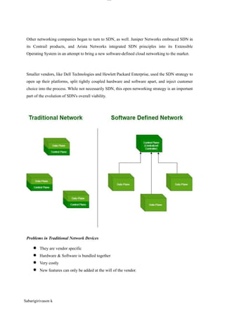
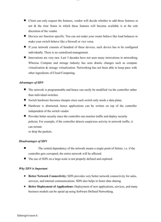
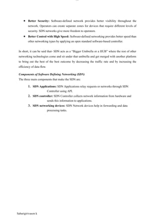
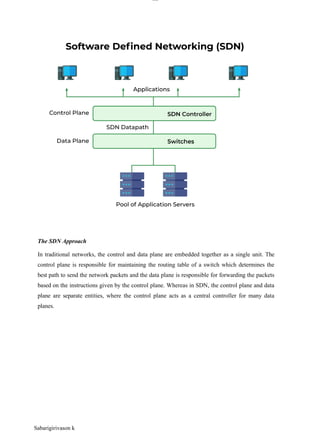
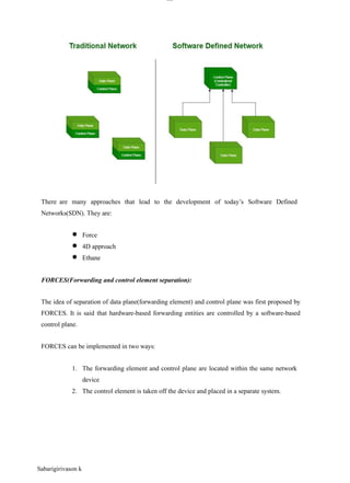
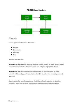
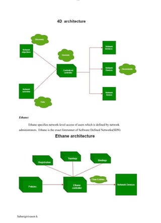
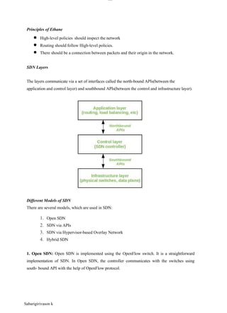
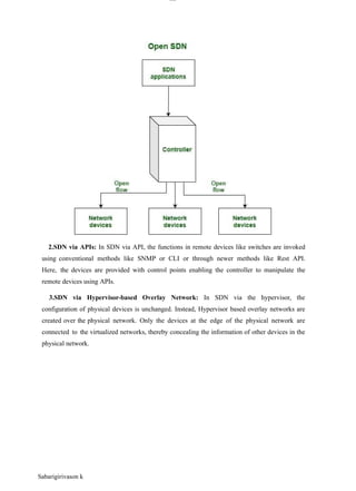
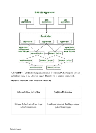
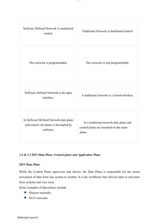
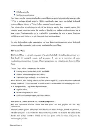
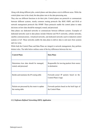
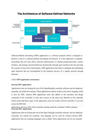
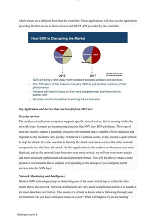
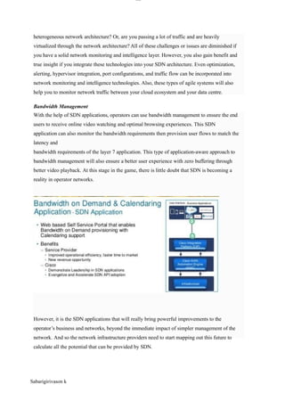
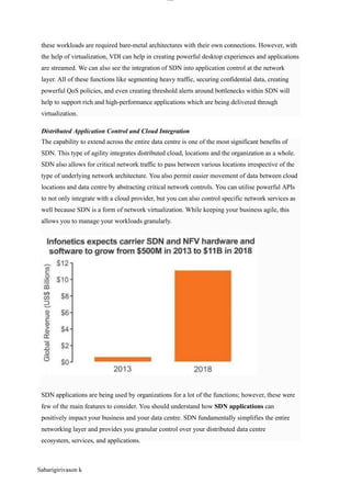
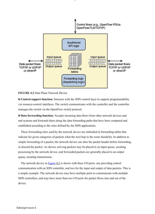
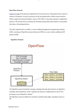
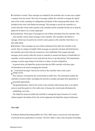
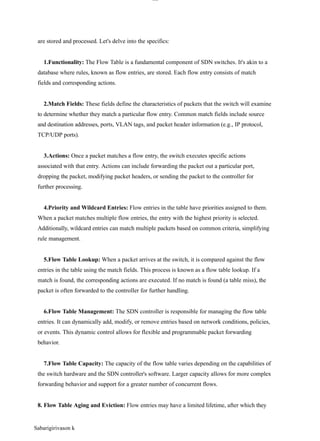
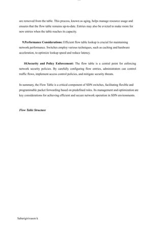
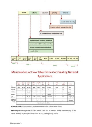


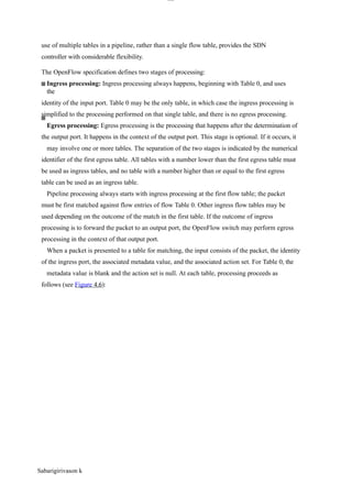
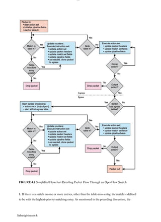
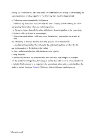
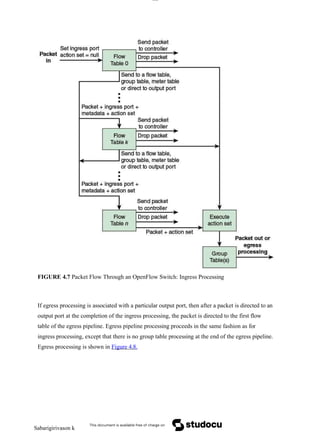
![lOM
oAR cP
SD| 30016045
FIGURE 4.8 Packet Flow Through OpenFlow Switch: Egress Processing
Control Plane Functions
Figure 5.2 illustrates the functions performed by SDN controllers. The figure illustrates the
essential functions that any controller should provide, as suggested in a paper by Kreutz [
KREU15], which include the following:
Sabarigirivason k](https://image.slidesharecdn.com/sdnnotes2-250303094042-b5d96d0e/85/SDN-NOTES-2-pptx-for-engineering-students-36-320.jpg)
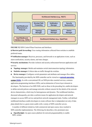
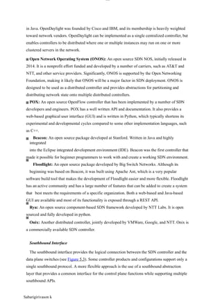
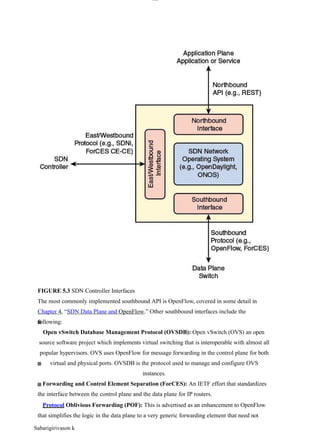
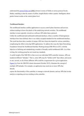
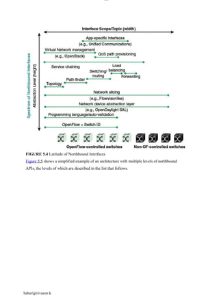
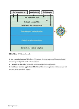
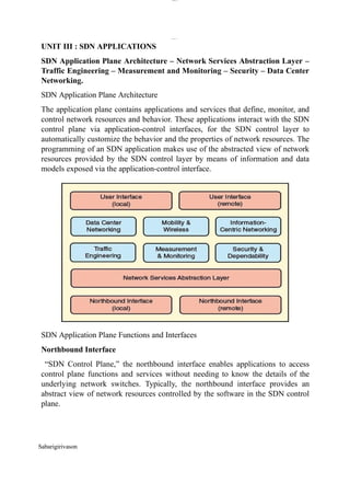
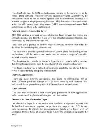
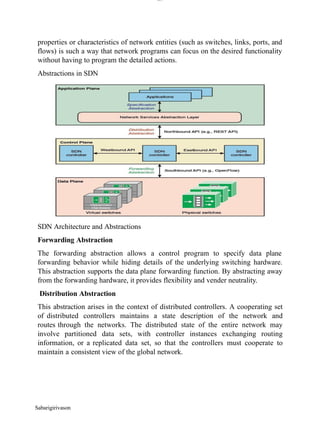
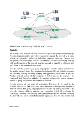
![lOM
oARcPSD|300 160 4
5
operates in the SDN controller. It translates high-level policies and queries into
low-level flow rules and then issues the needed OpenFlow commands to install
these rules on the switches.
Frenetic Architecture
The program combines forwarding functionality with monitoring web traffic
functionality. Consider the following Python program, which executes at the run-
time level, to control OpenFlow switches:
def switch_join(s):
pat1 = {inport:1}
pat2web = {inport:2, srcport:80}
pat2 = {inport:2}
install(s, pat1, DEFAULT,
[fwd(2)])
install(s, pat2web, HIGH, [fwd(1)])
install(s, pat2, DEFAULT, [fwd(1)])
query_stats(s, pat2web)
def stats_in(s, xid, pat, pkts,
bytes): print bytes
sleep(30)
query_stats(s, pat)
When a switch joins
the network, the
program installs
three forwarding
rules in the
switch for three types of traffic: traffic arriving on port 1, web traffic arriving on
port 2, and other traffic arriving on port 2. The second rule has HIGH priority and
so takes precedence over the third rule, which has default priority. The call to
query_stats generates a request for the counters associated with the pat2web rule.
Sabarigirivason](https://image.slidesharecdn.com/sdnnotes2-250303094042-b5d96d0e/85/SDN-NOTES-2-pptx-for-engineering-students-48-320.jpg)
![Sabarigirivason
lOM
oARcPSD|300 160 4
5
When the controller receives the reply, it invokes the stats_in handler. This
function prints the statistics polled on the previous iteration of the loop, waits 30
seconds, and then issues a request to the switch for statistics matching the same
rule.
With Frenetic, these two functions can be expressed separately, as follows:
def repeater():
rules=[Rule(inport:1, [fwd(2)])
Rule(inport:2, [fwd(1)])]
register(rules)
def web monitor():
q = (Select(bytes) *
Where(inport=2 & srcport=80) *
Every(30))
q >> Print()
def main():
repeate
r()
monitor()
With this code, it would be easy to change the monitor program or swap it out
for another monitor program without touching the repeater code, and similarly for
the changes to the repeater program.
Traffic Engineering
Traffic engineering is a method for dynamically analyzing, regulating,
and predicting the behavior of data flowing in networks with the aim of
performance optimization to meet service level agreements (SLAs). Traffic
engineering involves establishing routing and forwarding policies based on
QoS requirements. With SDN, the task of traffic engineering should be
considerably simplified compared with a non-SDN network. SDN offers a
uniform global view of heterogeneous equipment and powerful tools for
configuring and managing network switches.
• On-demand virtual private networks
• Load balancing
• Energy-aware routing
• Quality of service (QoS) for broadband access networks
• Scheduling/optimization
• Traffic engineering with minimal overhead](https://image.slidesharecdn.com/sdnnotes2-250303094042-b5d96d0e/85/SDN-NOTES-2-pptx-for-engineering-students-49-320.jpg)
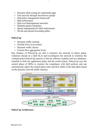
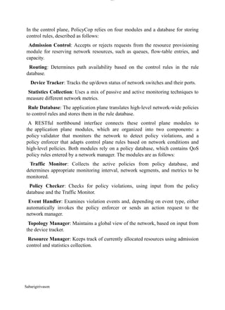
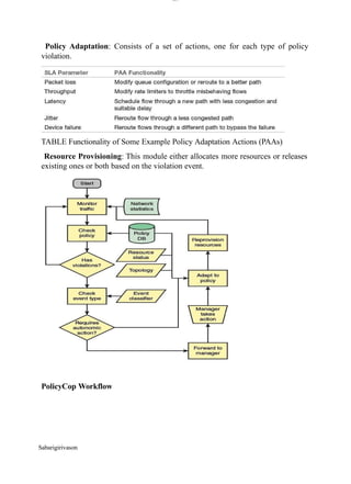
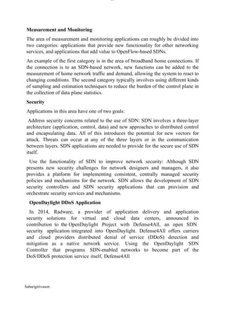
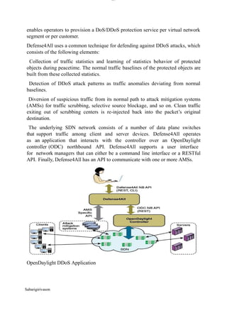
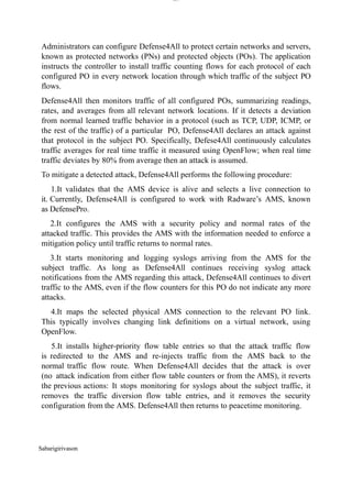
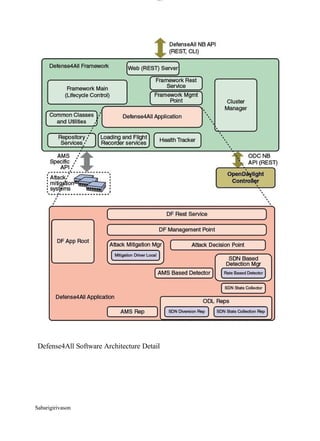
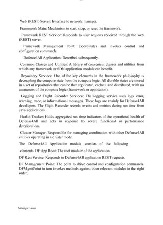
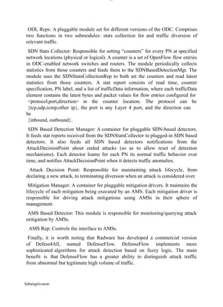
![Sabarigirivason
lOM
oARcPSD|300 160 4
5
Data Center Networking
So far we’ve discussed three areas of SDN applications: traffic engineering,
measurement and monitoring, and security. The provided examples of these
applications suggest the broad range of use cases for them, in many different kinds
of networks. The remaining three applications areas (data center networking,
mobility and wireless, and information-centric networking) have use cases in
specific types of networks.
Cloud computing, big data, large enterprise networks, and even in many cases,
smaller enterprise networks, depend strongly on highly scalable and efficient data
centers. [KREU15] lists the following as key requirements for data centers: high
and flexible cross-section bandwidth and low latency, QoS based on the
application requirements, high levels of resilience, intelligent resource utilization
to reduce energy consumption and improve overall efficiency, and agility in
provisioning network resources (for example, by means of network virtualization
and orchestration with computing and storage).
With traditional network architectures, many of these requirements are difficult to
satisfy because of the complexity and inflexibility of the network. SDN offers the
promise of substantial improvement in the ability to rapidly modify data center
network configurations, to flexibly respond to user needs, and to ensure efficient
operation of the network.
The remainder of this subsection, examines two example data center SDN
applications.
Big Data over SDN
The approach leverages the capabilities of SDN to provide application-aware
networking. It also exploits characteristics of structured big data applications as
well as recent trends in dynamically reconfigurable optical circuits. With respect
to structured big data applications, many of these applications process data
according to well-defined computation patterns, and also have a centralized
management structure that makes it possible to leverage application-level
information to optimize the network. That is, knowing the anticipated
computation patterns of the big data application, it is possible to intelligently
deploy the data across the big](https://image.slidesharecdn.com/sdnnotes2-250303094042-b5d96d0e/85/SDN-NOTES-2-pptx-for-engineering-students-59-320.jpg)
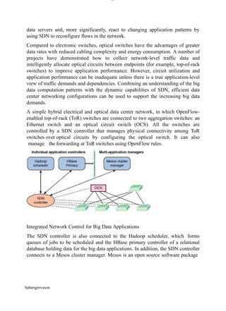
![lOM
oARcPSD|300 160 4
5
that provides scheduling and resource allocation services across distributed
applications.
The SDN controller makes available network topology and traffic information to
the Mesos cluster manager. In turn, the SDN controller accepts traffic demand
request from Mesos managers.
Cloud Networking over SDN
Cloud Network as a Service (CloudNaaS) is a cloud networking system that
exploits OpenFlow SDN capabilities to provide a greater degree of control over
cloud network functions by the cloud customer [BENS11]. CloudNaaS enables
users to deploy applications that include a number of network functions, such as
virtual network isolation, custom addressing, service differentiation, and flexible
interposition of various middleboxes. CloudNaaS primitives are directly
implemented within the cloud infrastructure itself using high-speed programmable
network elements, making CloudNaaS highly efficient.
Various Steps in the CloudNaaS Framework
Sabarigirivason](https://image.slidesharecdn.com/sdnnotes2-250303094042-b5d96d0e/85/SDN-NOTES-2-pptx-for-engineering-students-61-320.jpg)