Download to read offline
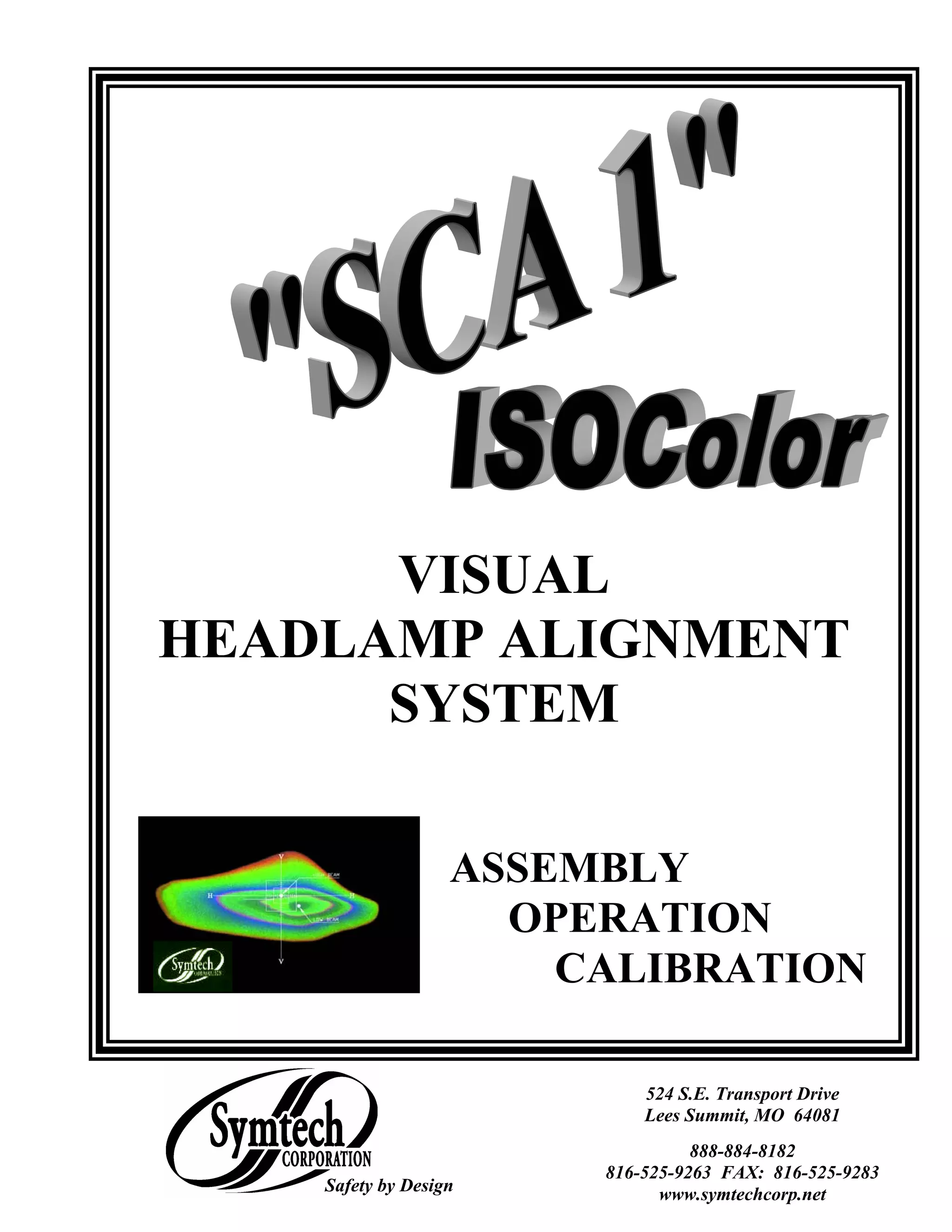


The document provides assembly and operating instructions for the SCA 1 ISOColor Visual Headlamp Alignment System. It includes: 1. An introduction describing the system's components and benefits of the ISOColor technology. 2. Steps for assembling the base and wheels, mast and glide plate, optical alignment head, and sighting unit. 3. Guidelines for preparing the alignment bay and vehicle, and using the system to align a vehicle's headlamps.


