Download to read offline
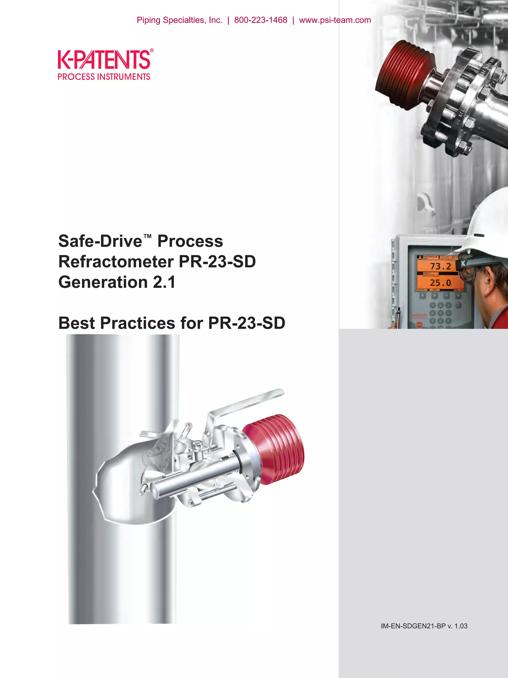
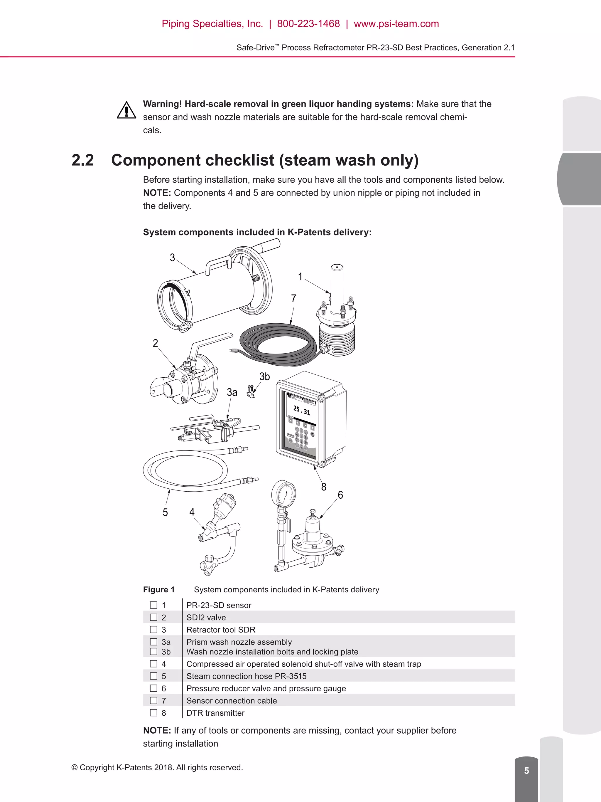
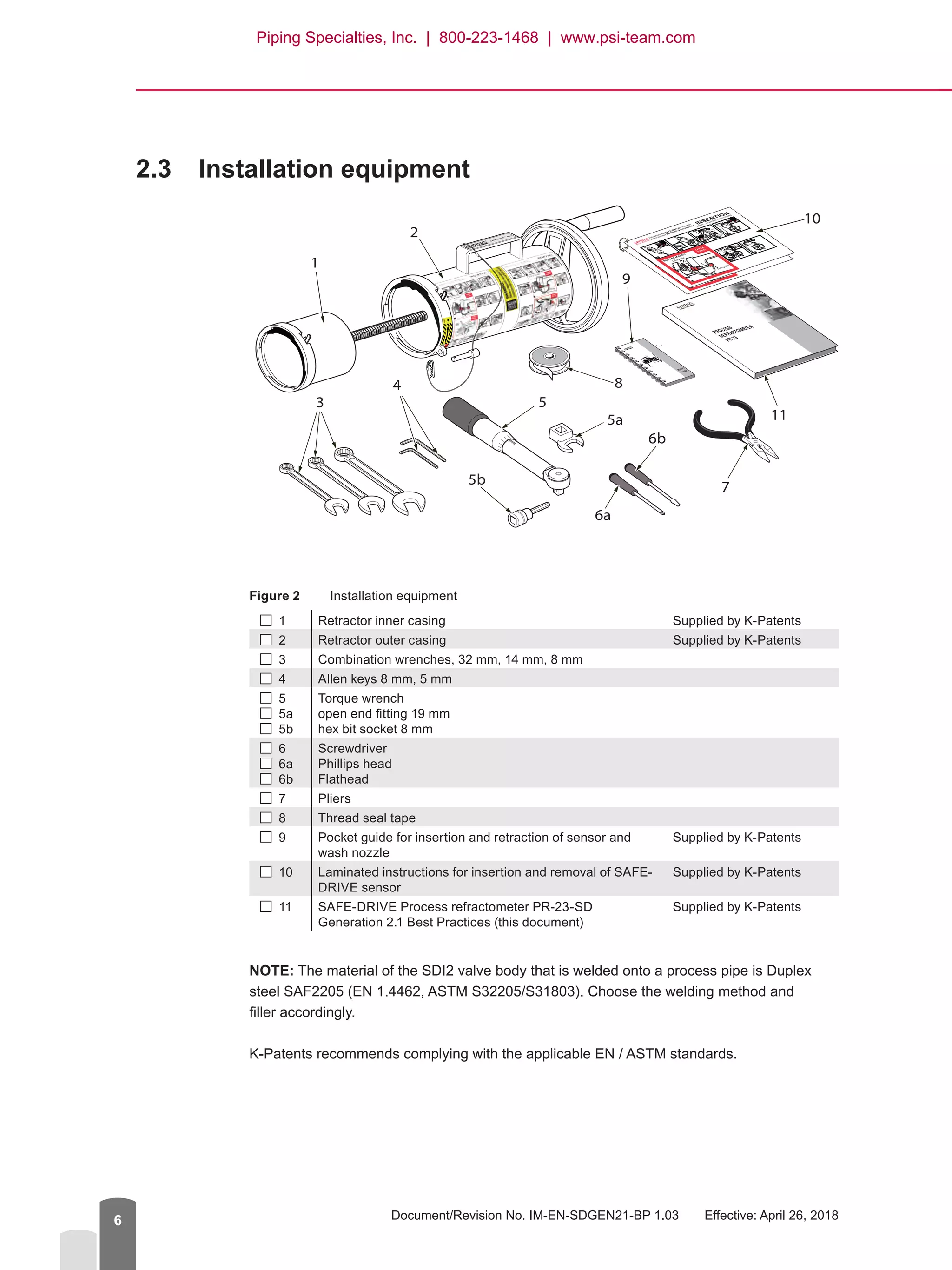
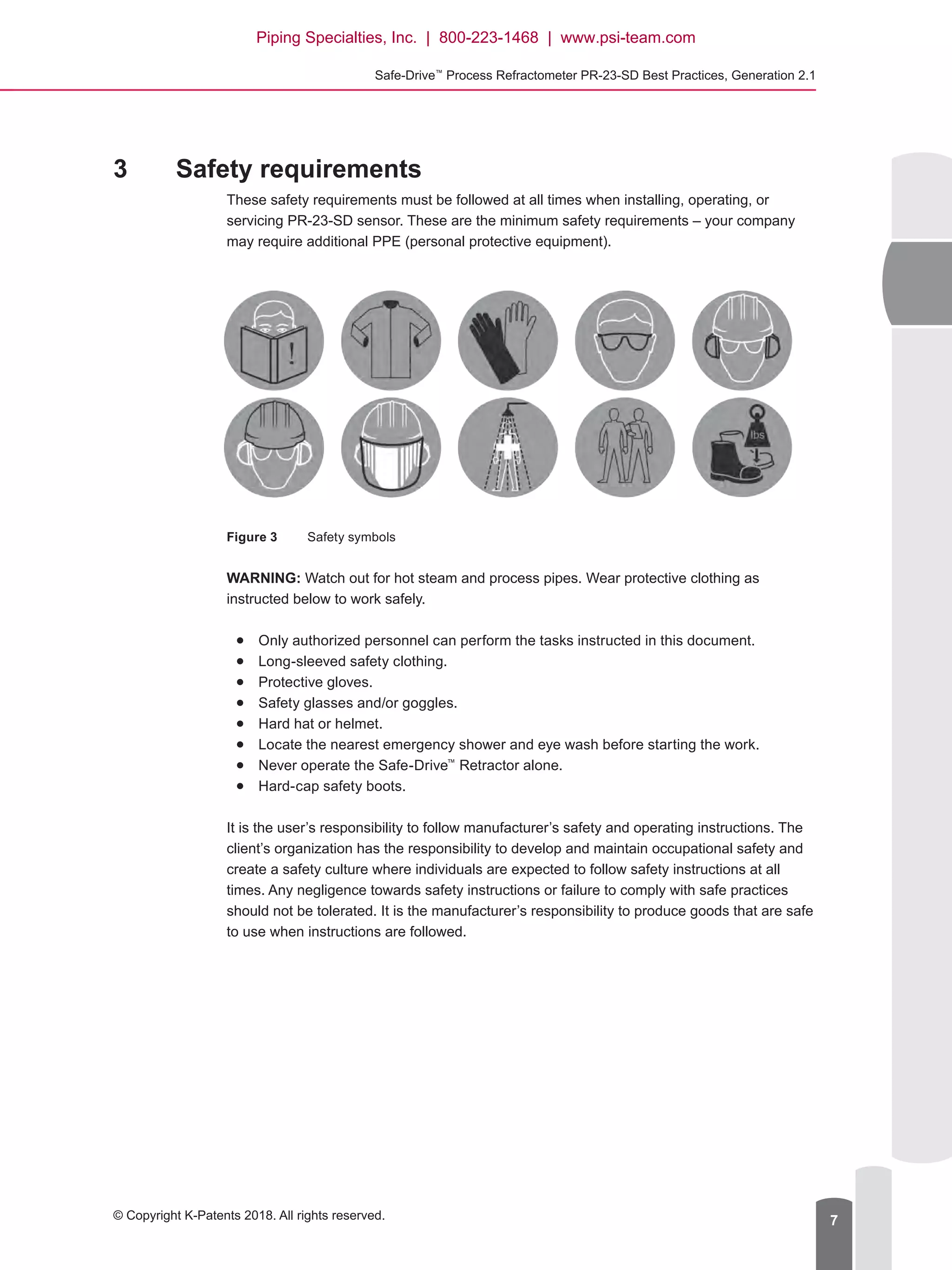
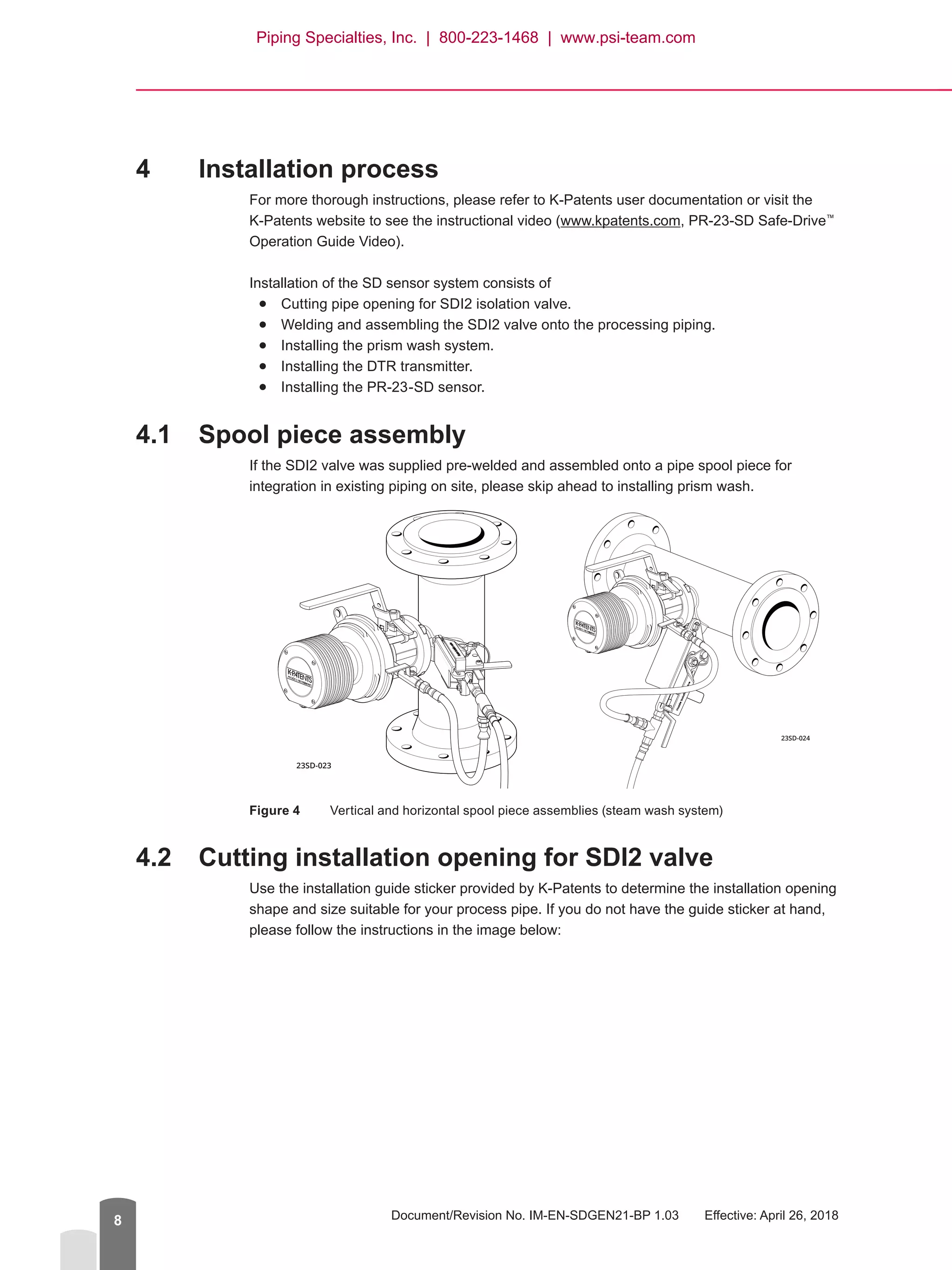
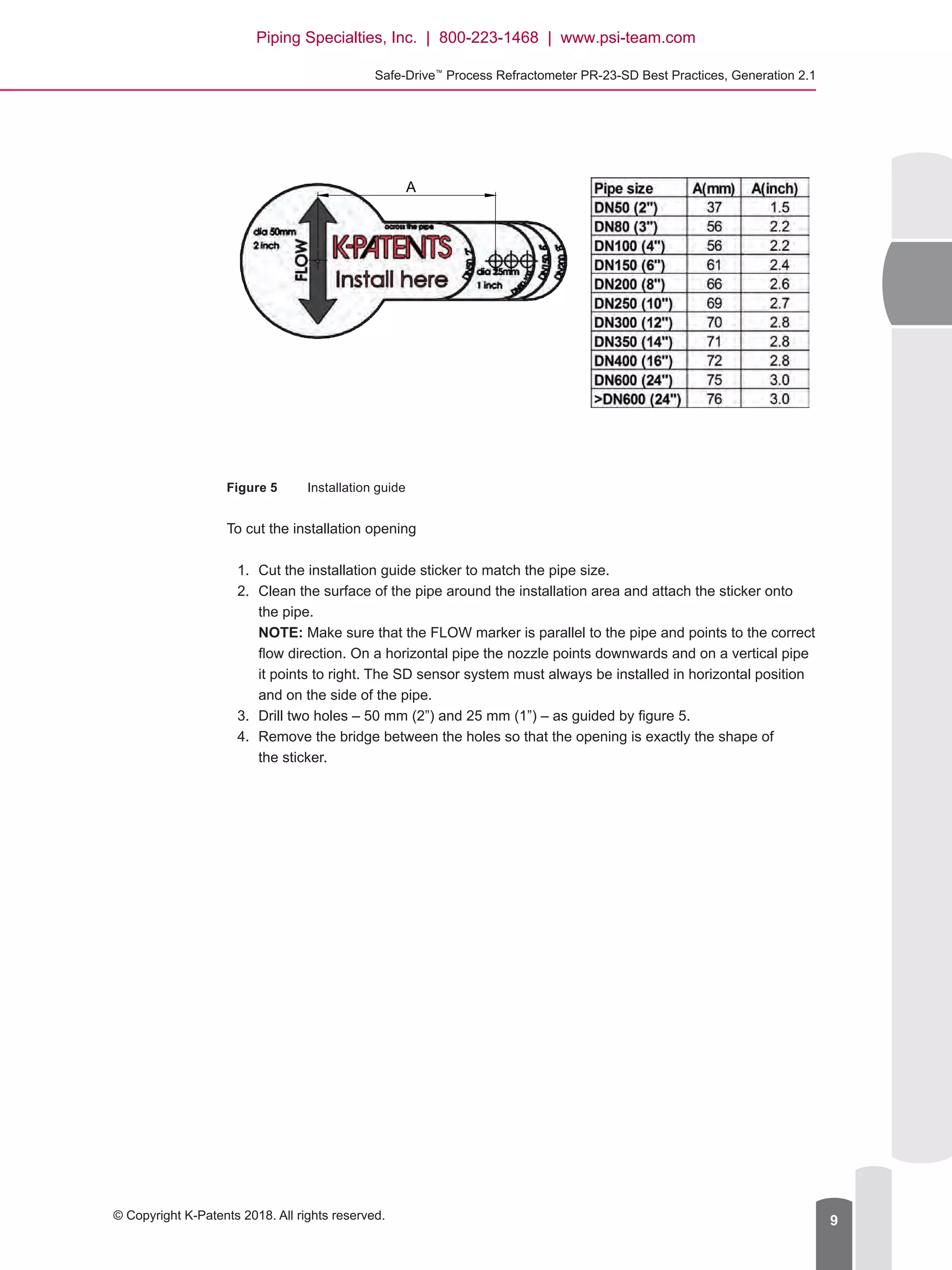
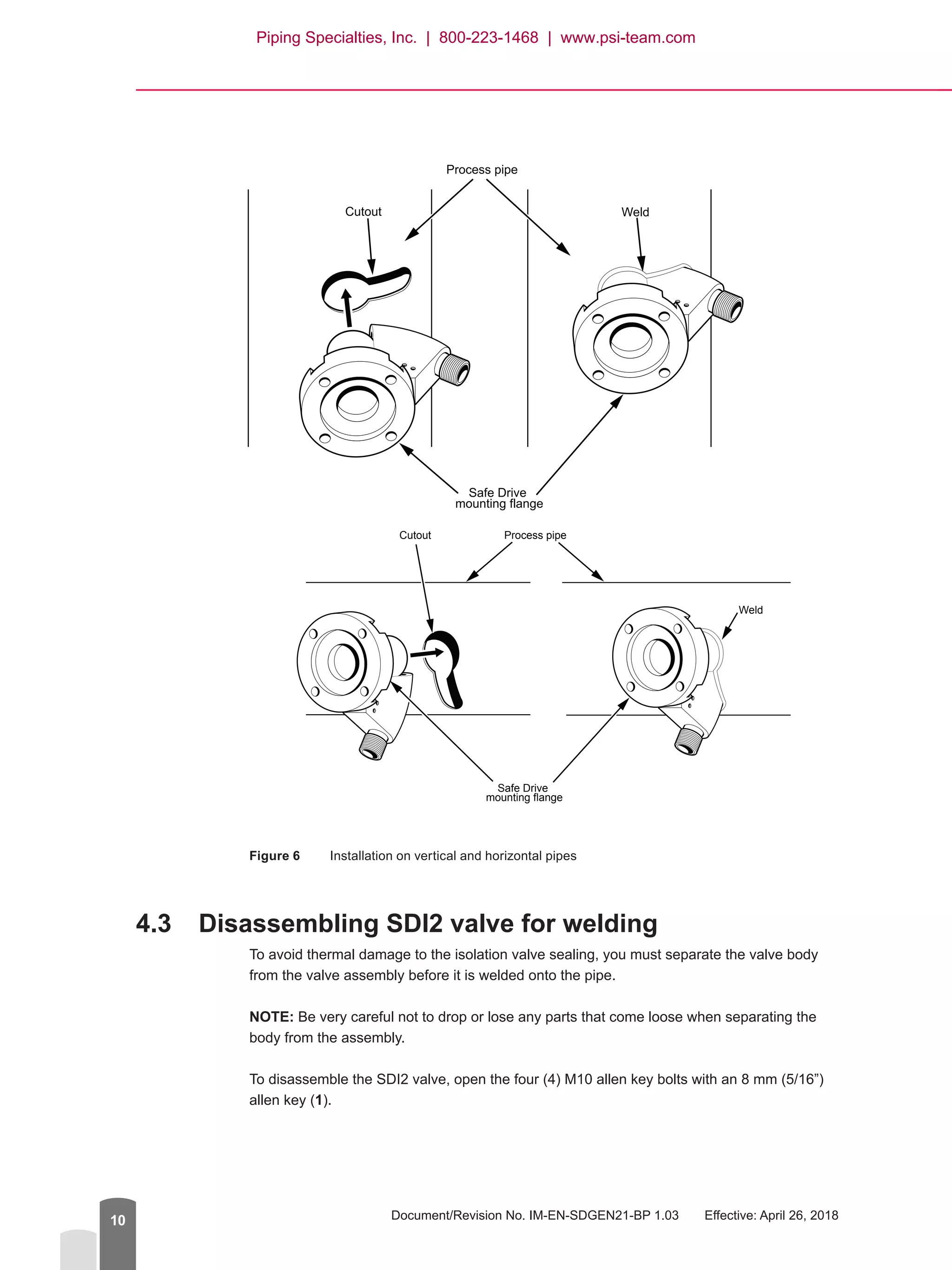
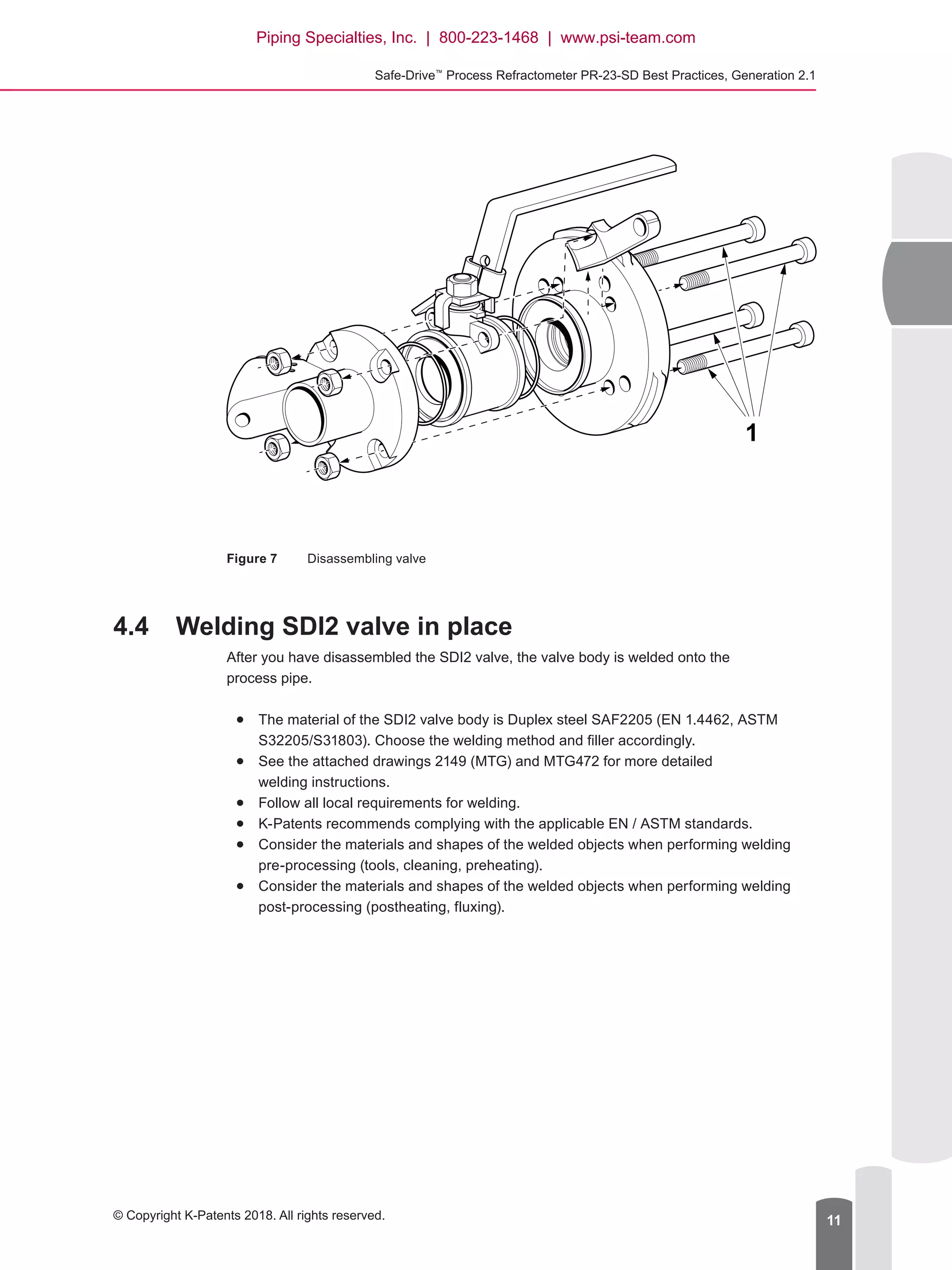
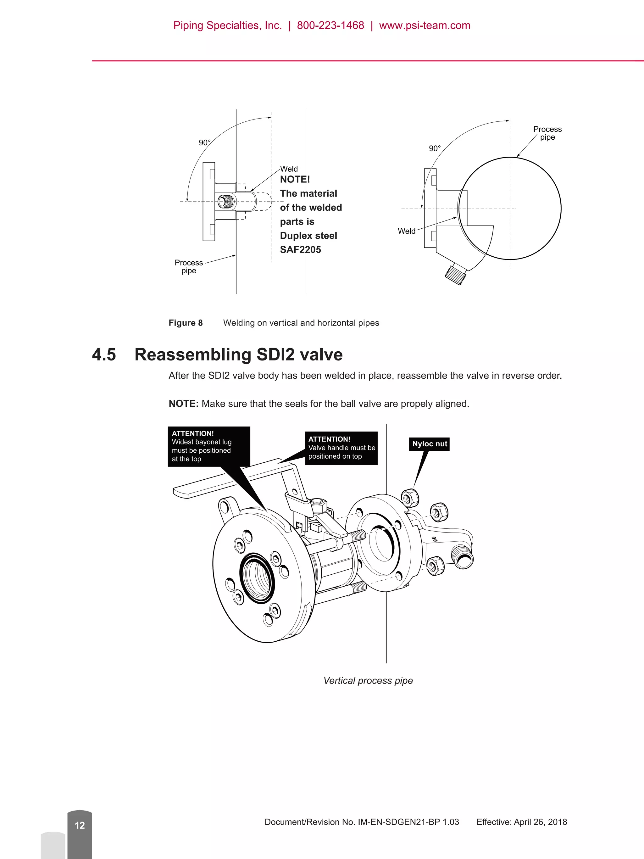
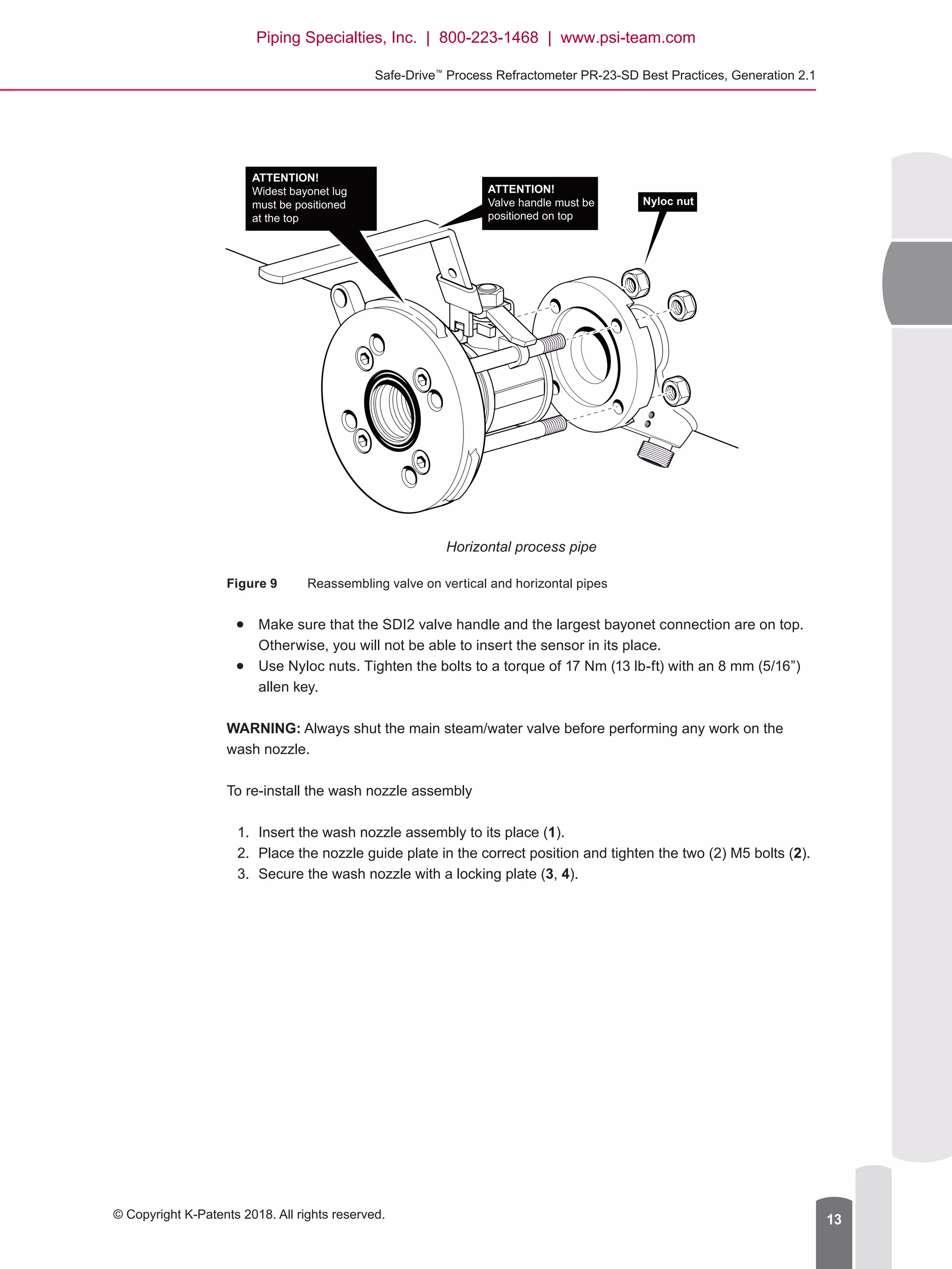
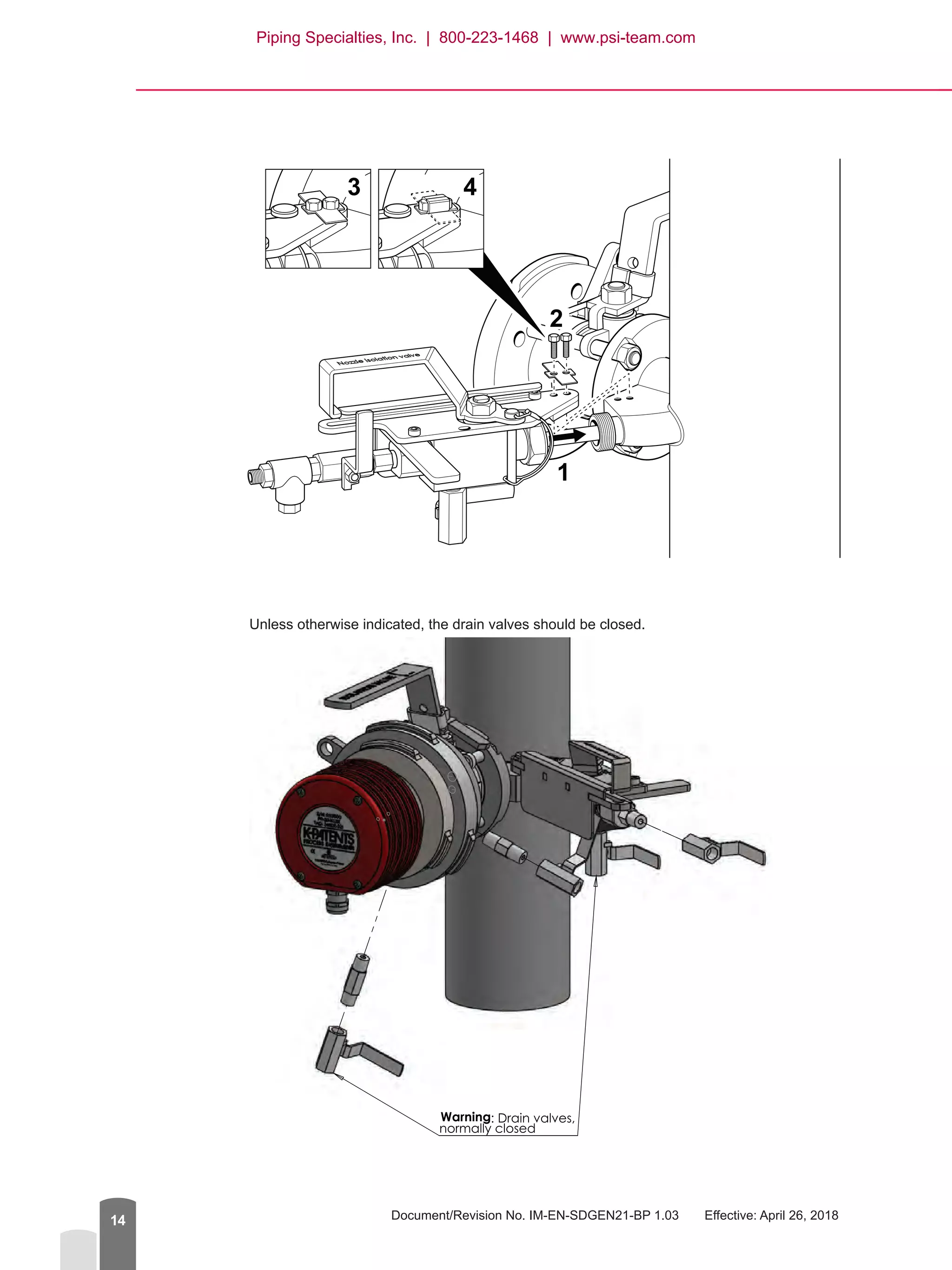
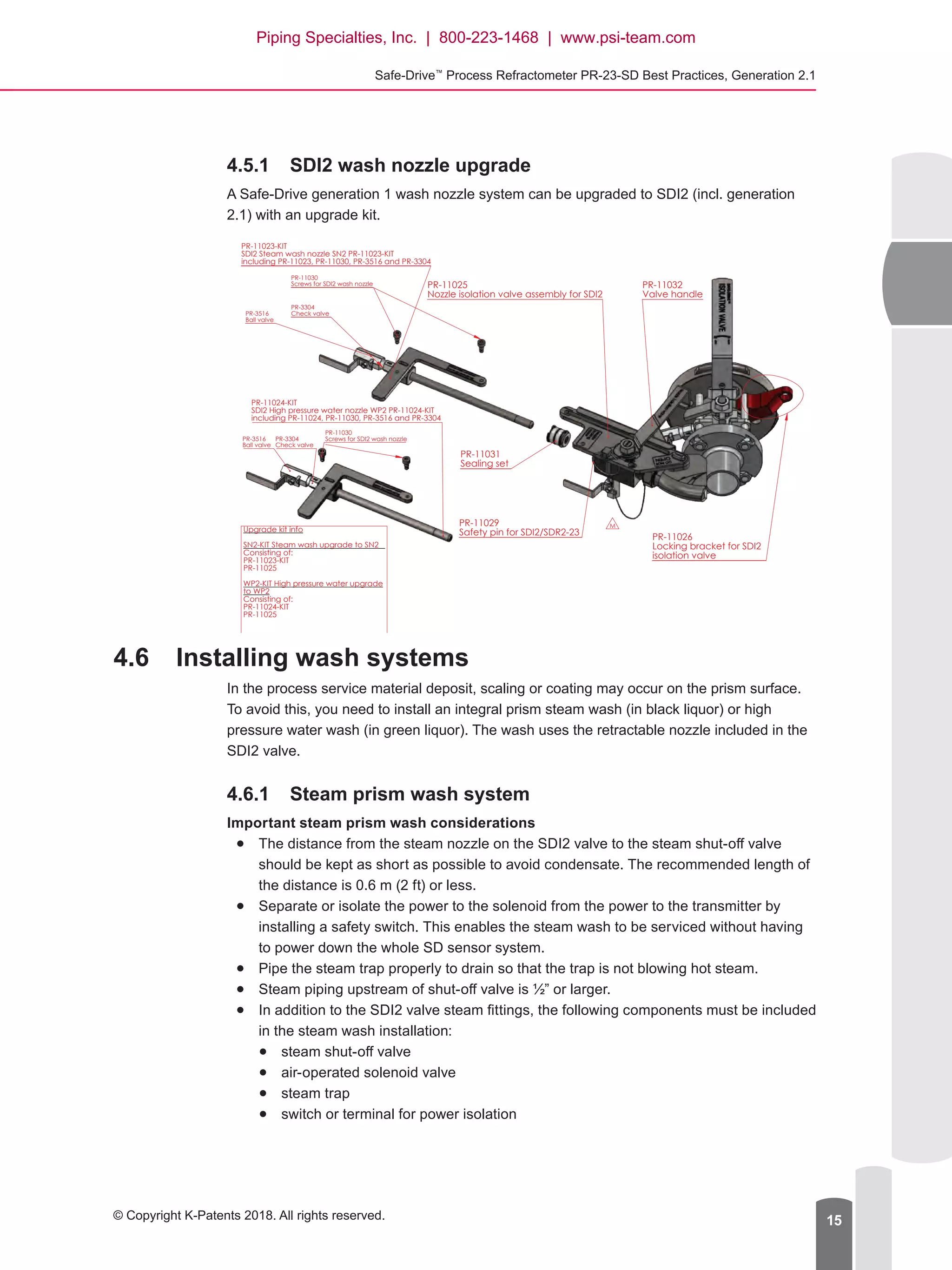
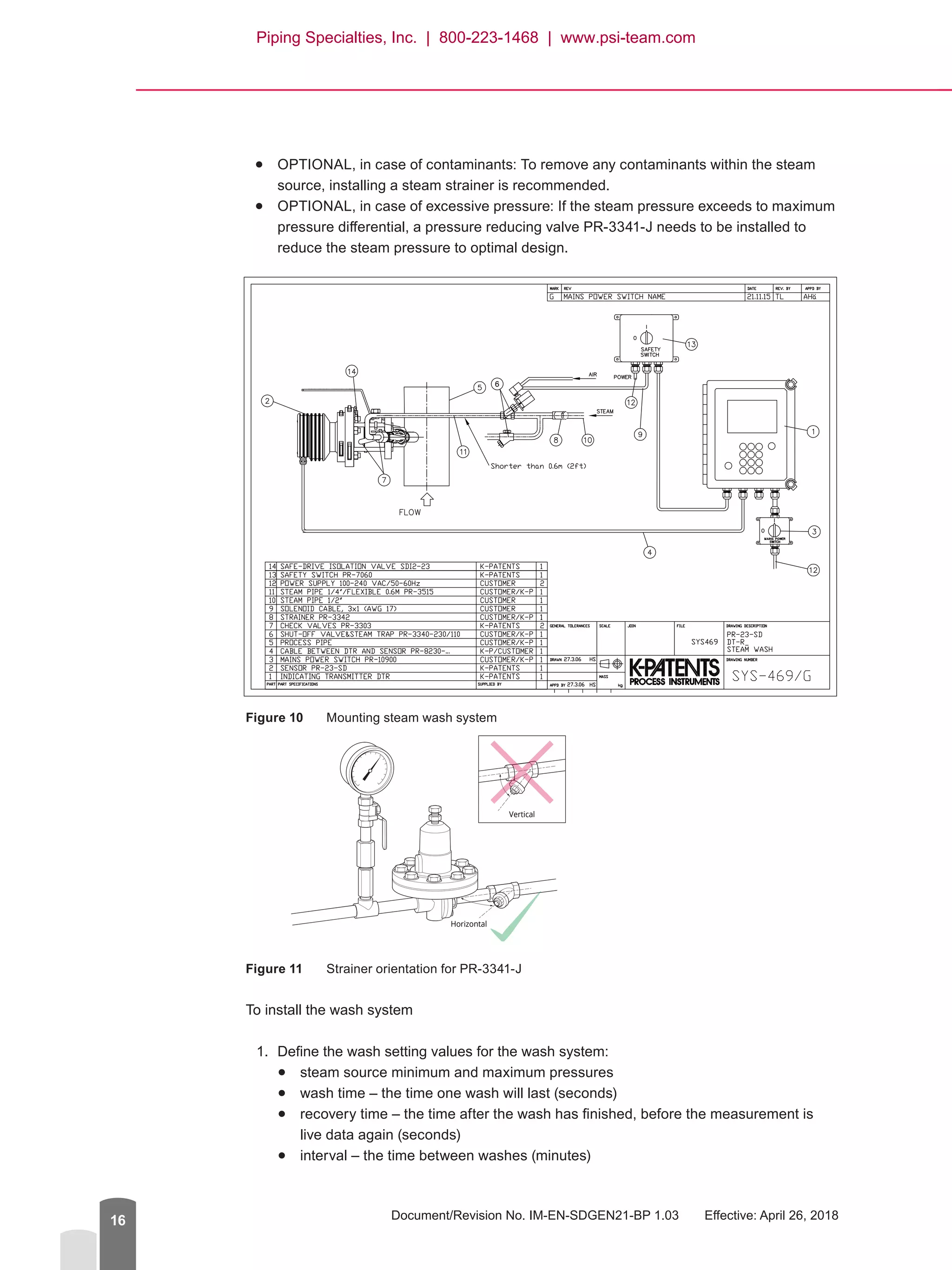
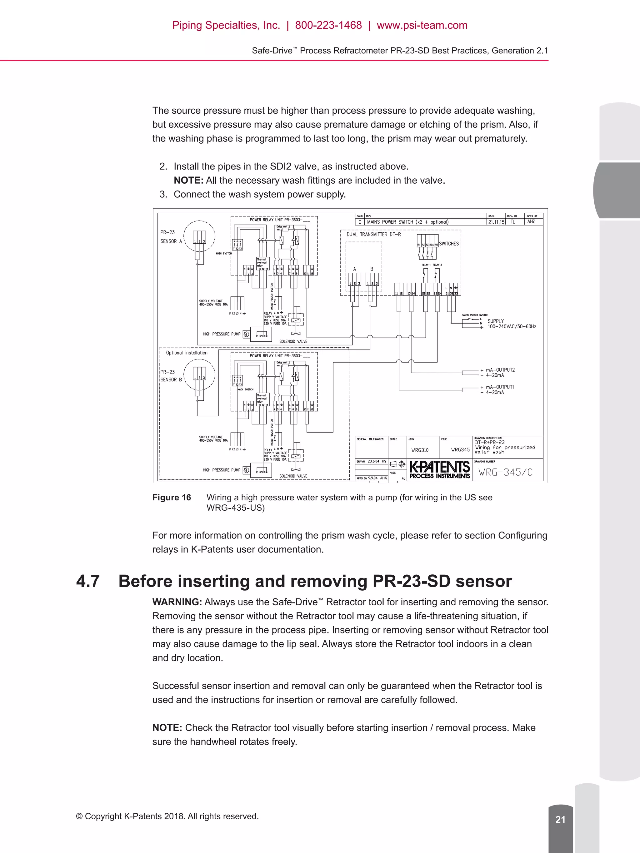
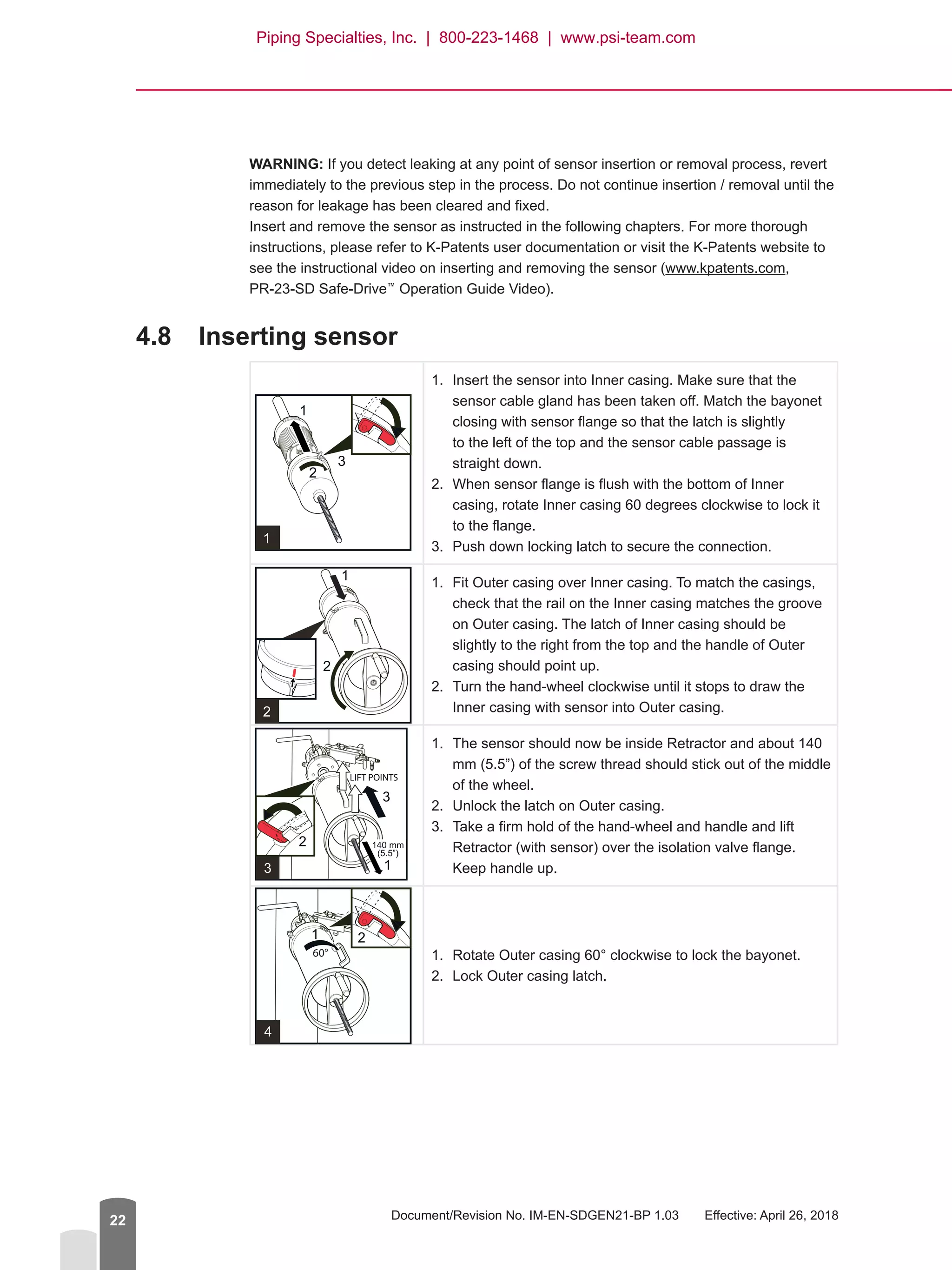
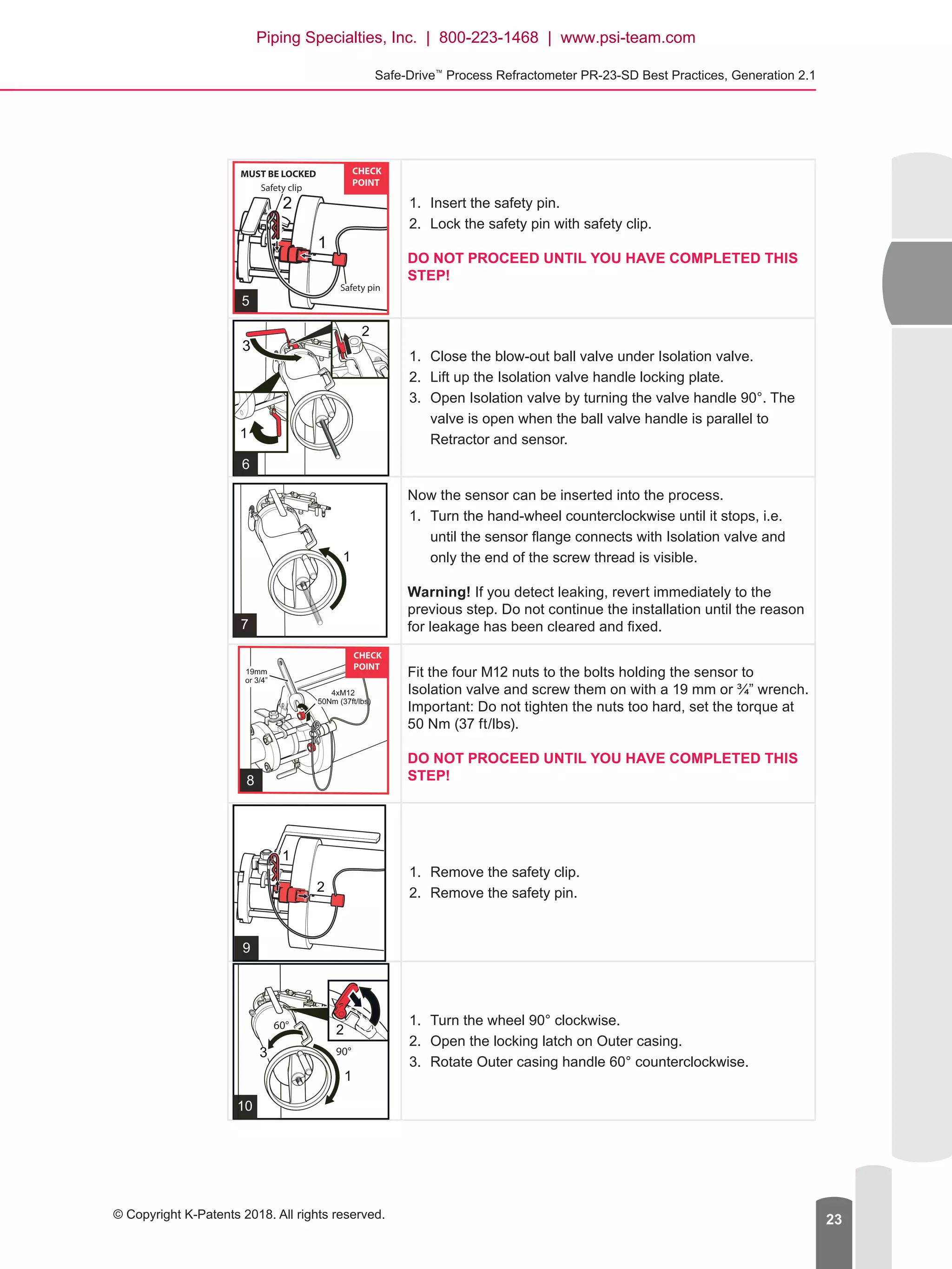
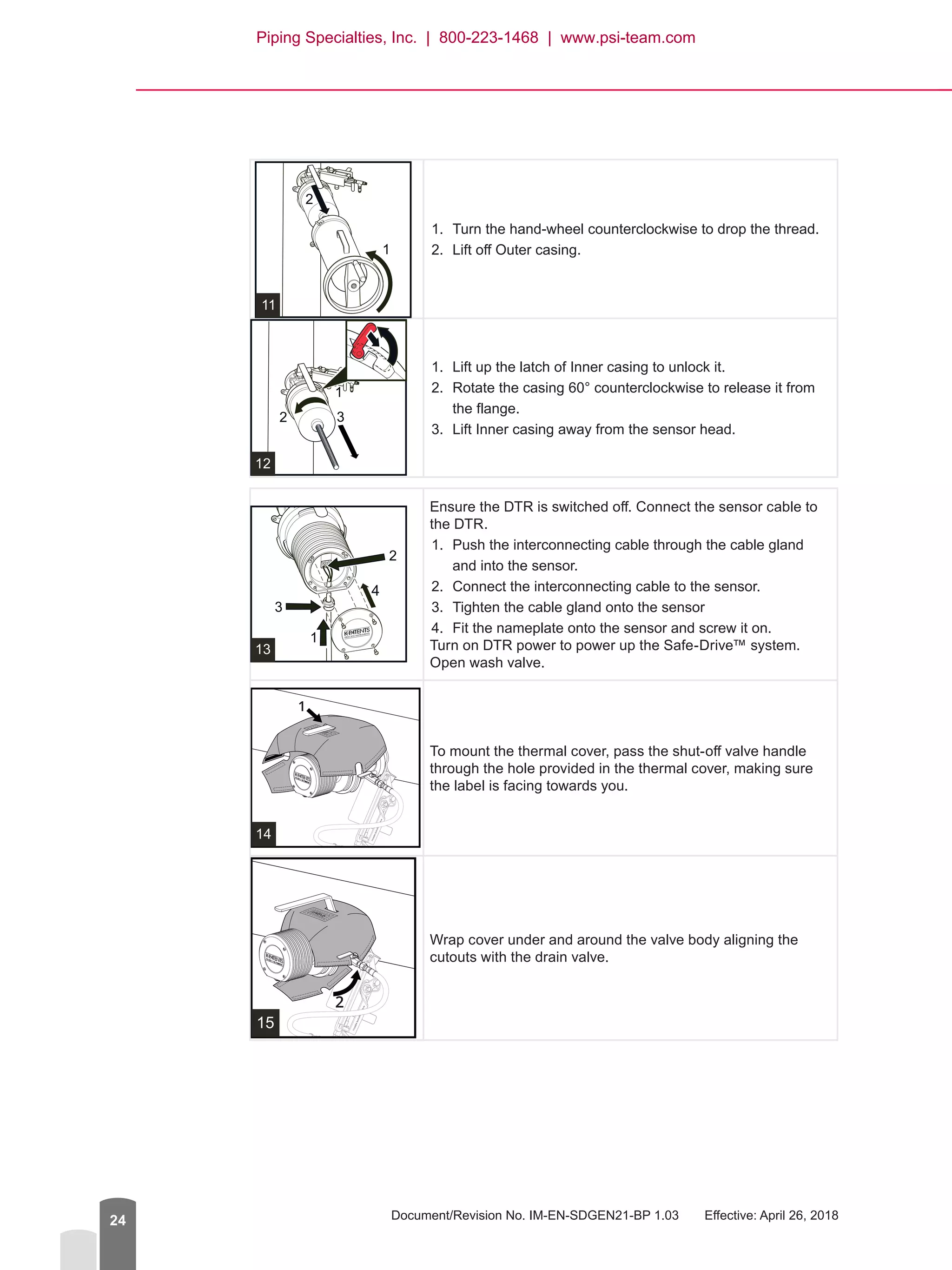
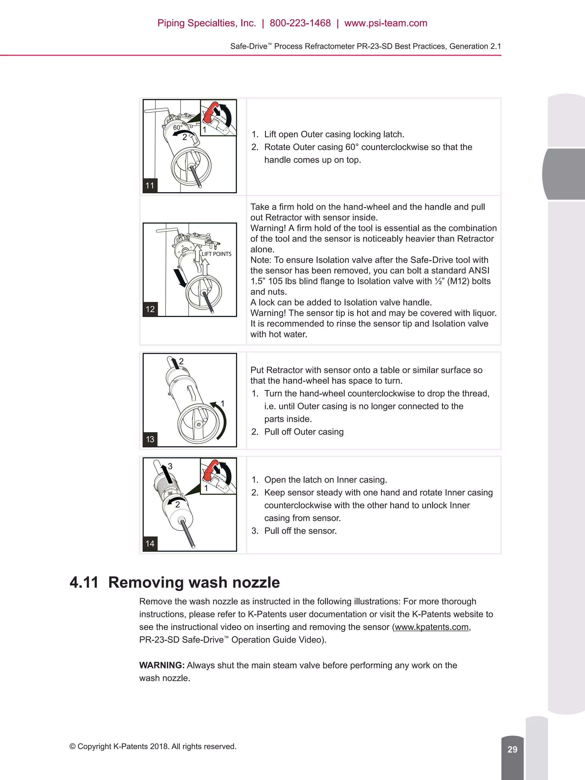
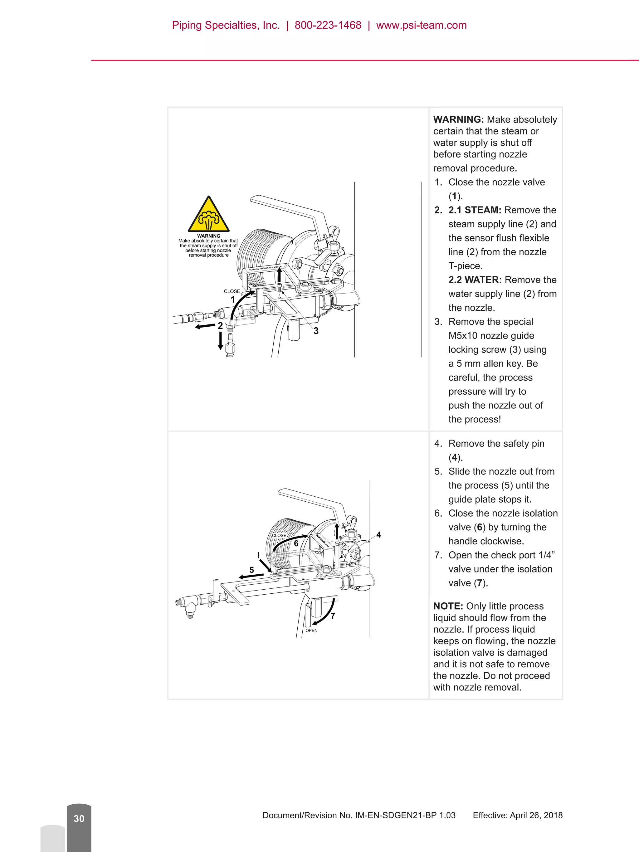
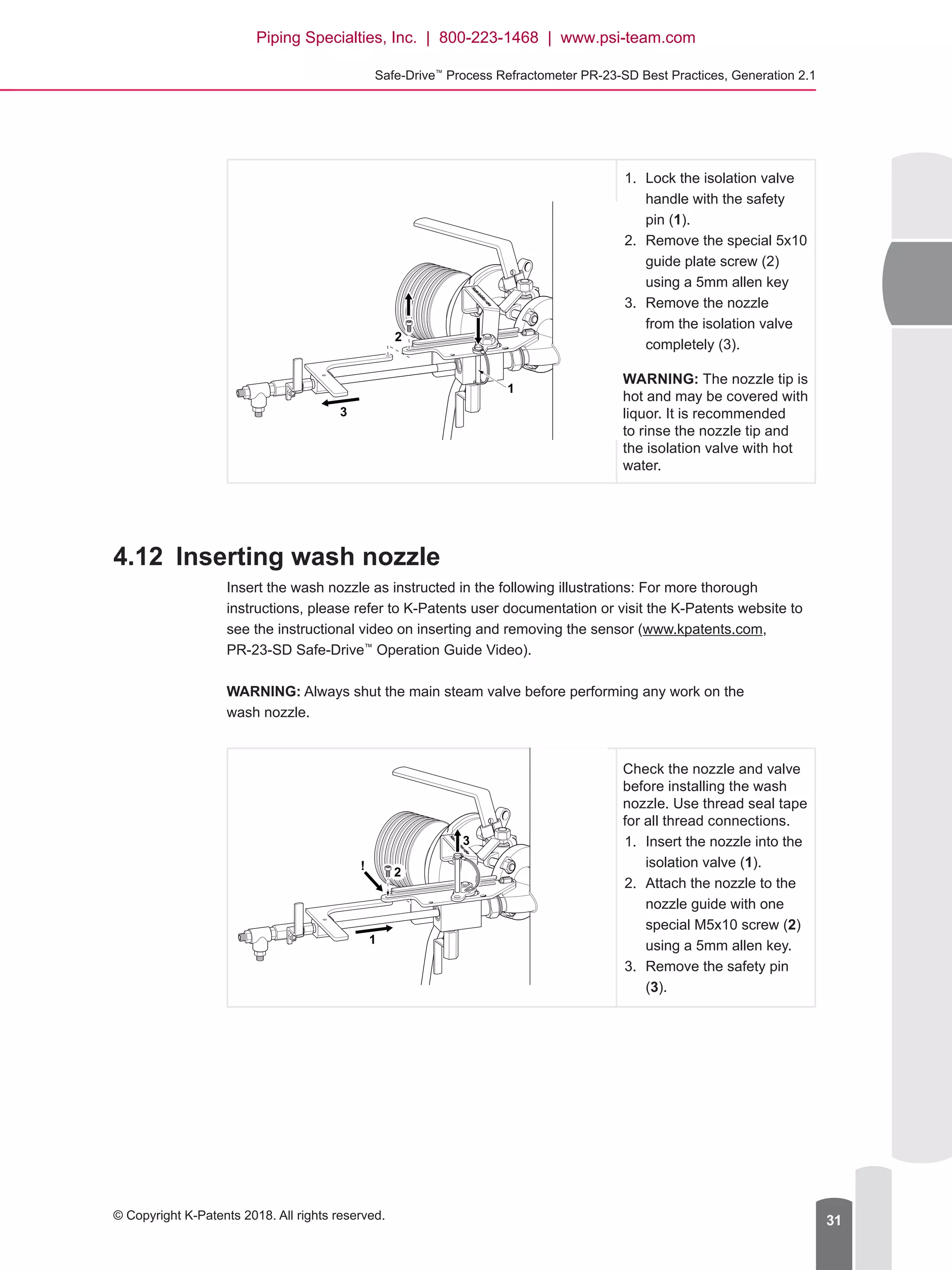
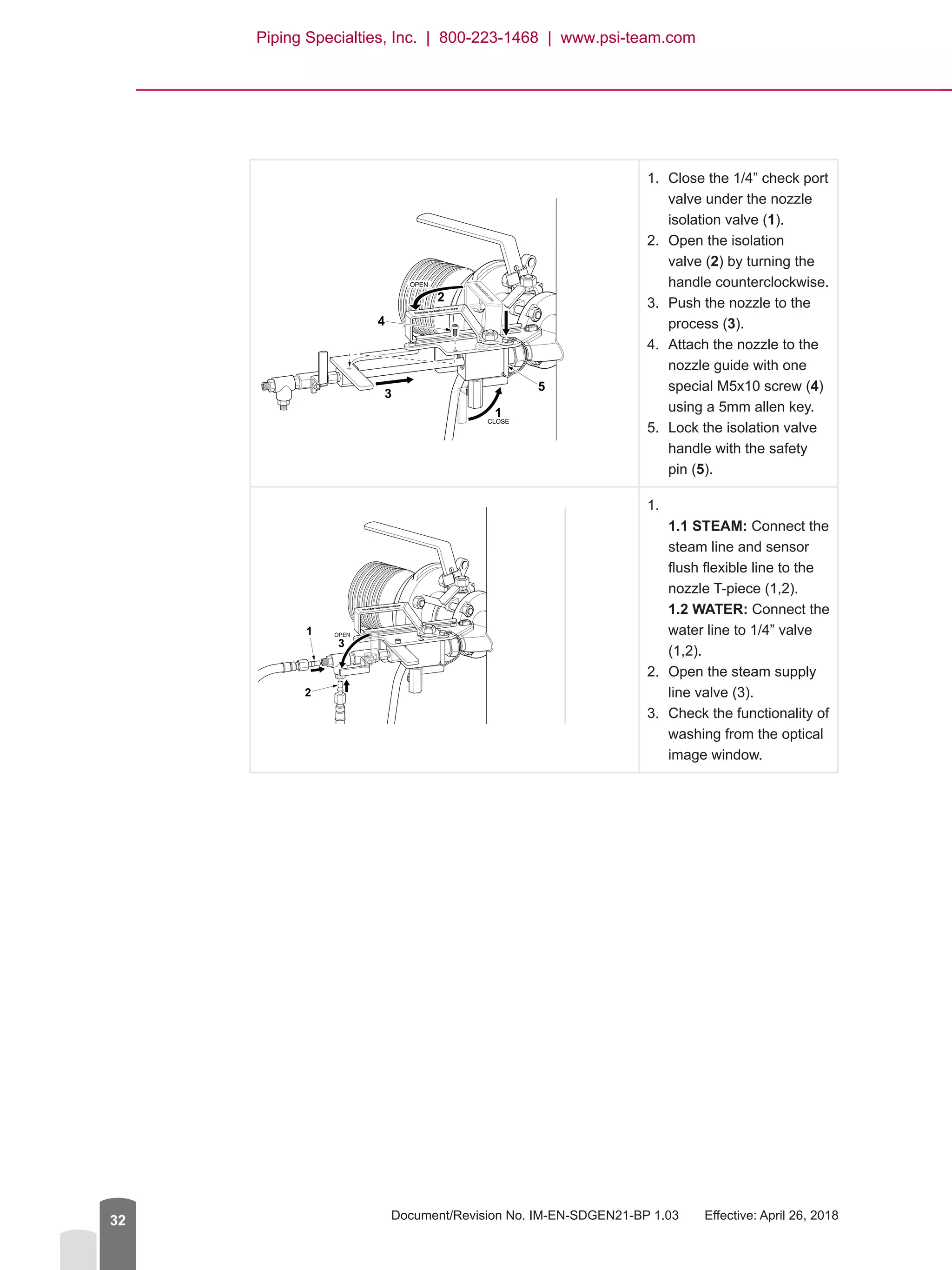
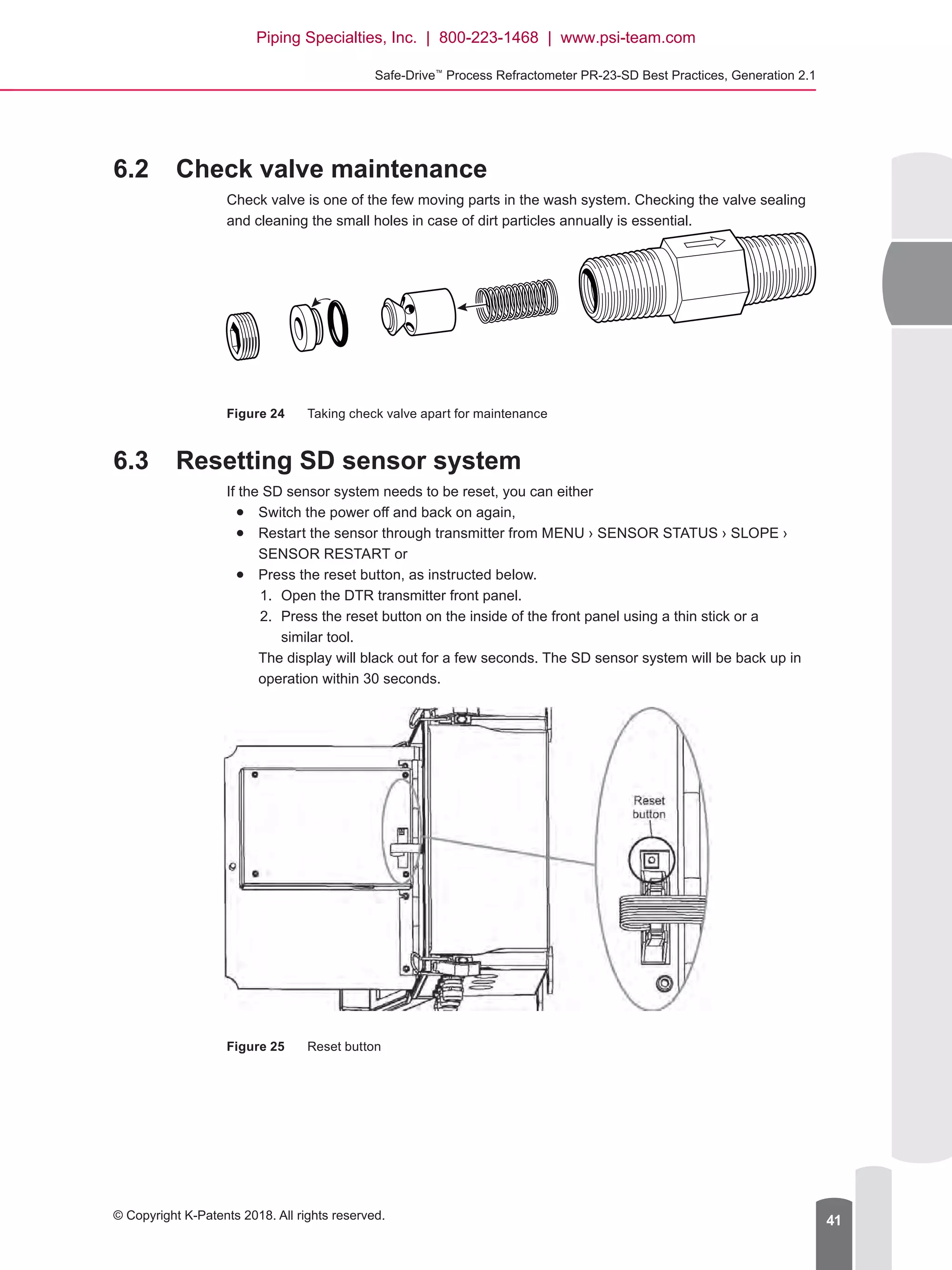
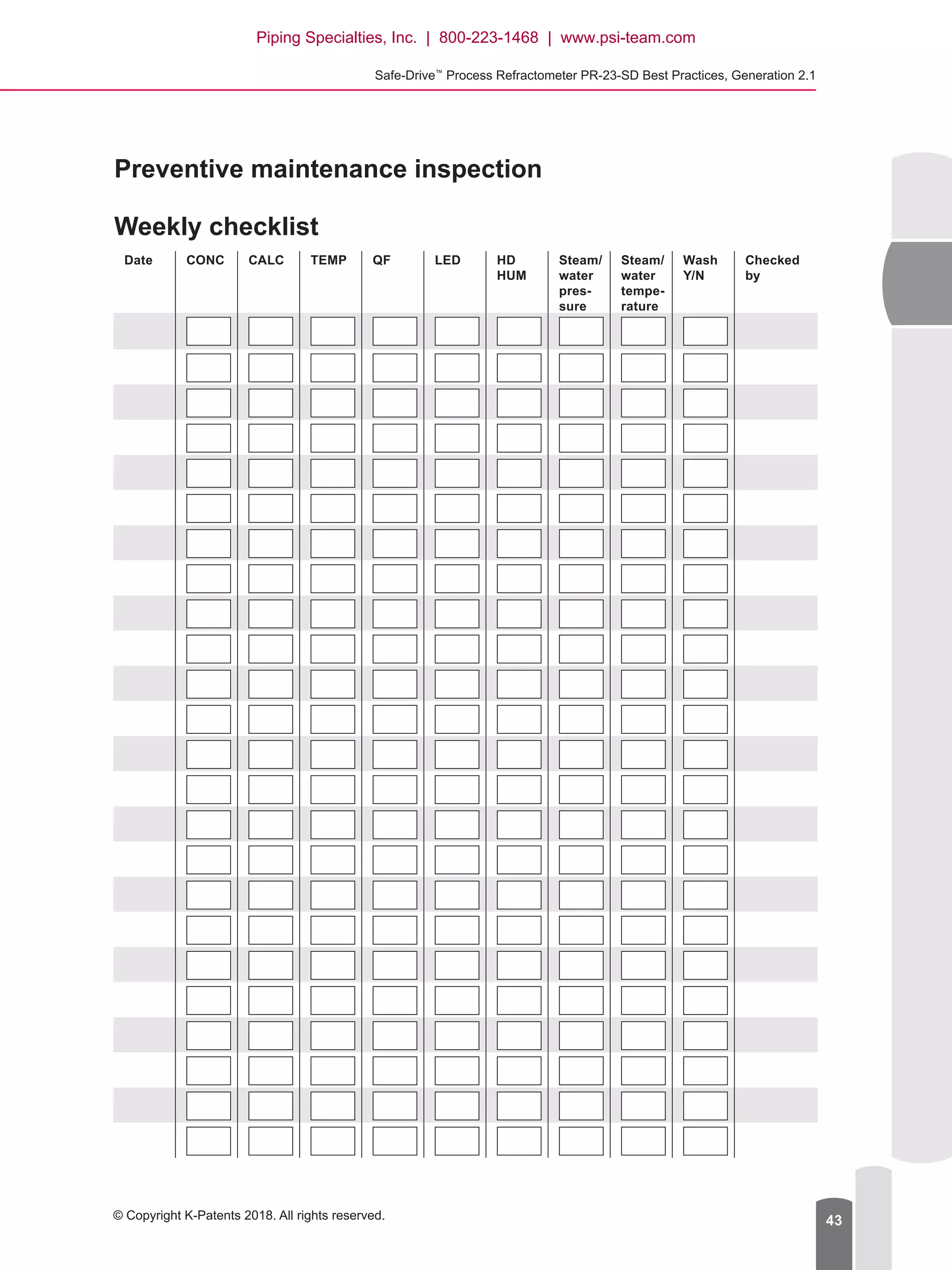


This document provides best practices for installing, operating, and maintaining the Safe-DriveTM Process Refractometer PR-23-SD. It outlines important safety requirements and gives step-by-step instructions for installing the sensor system, including cutting an opening for the isolation valve, welding the valve in place, installing the prism wash system, and inserting the PR-23-SD sensor. The document also covers commissioning, operation, and preventative maintenance of the sensor system.


