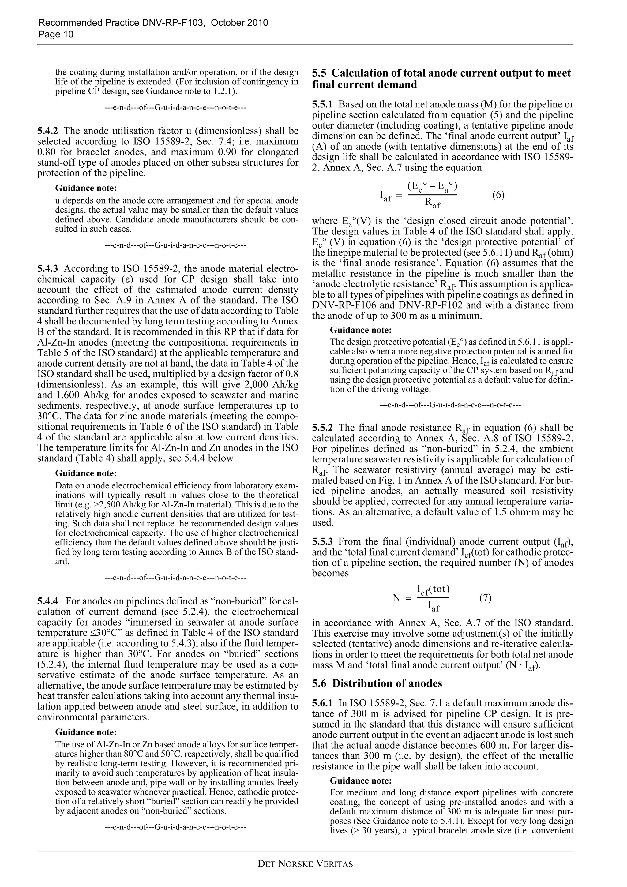
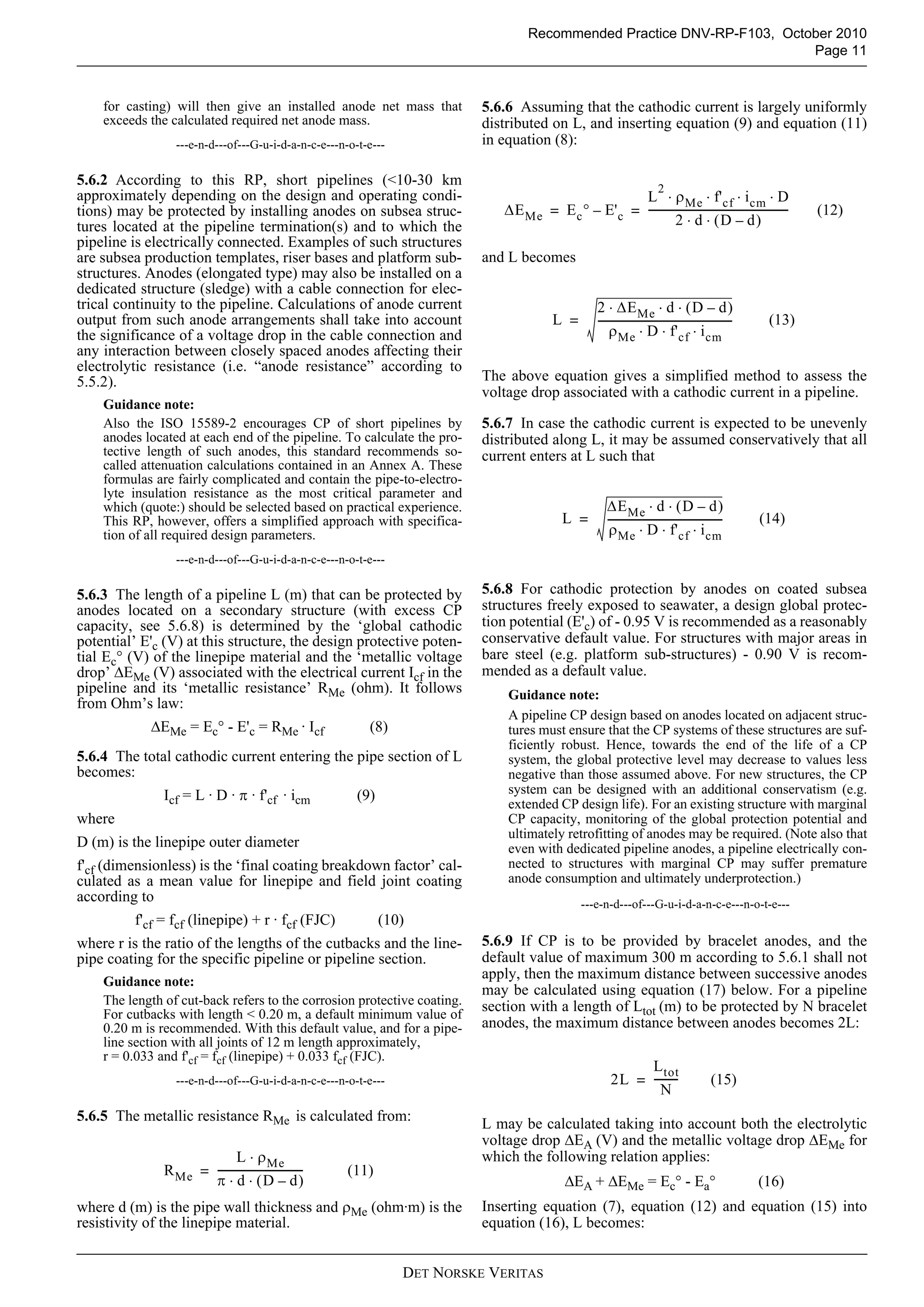
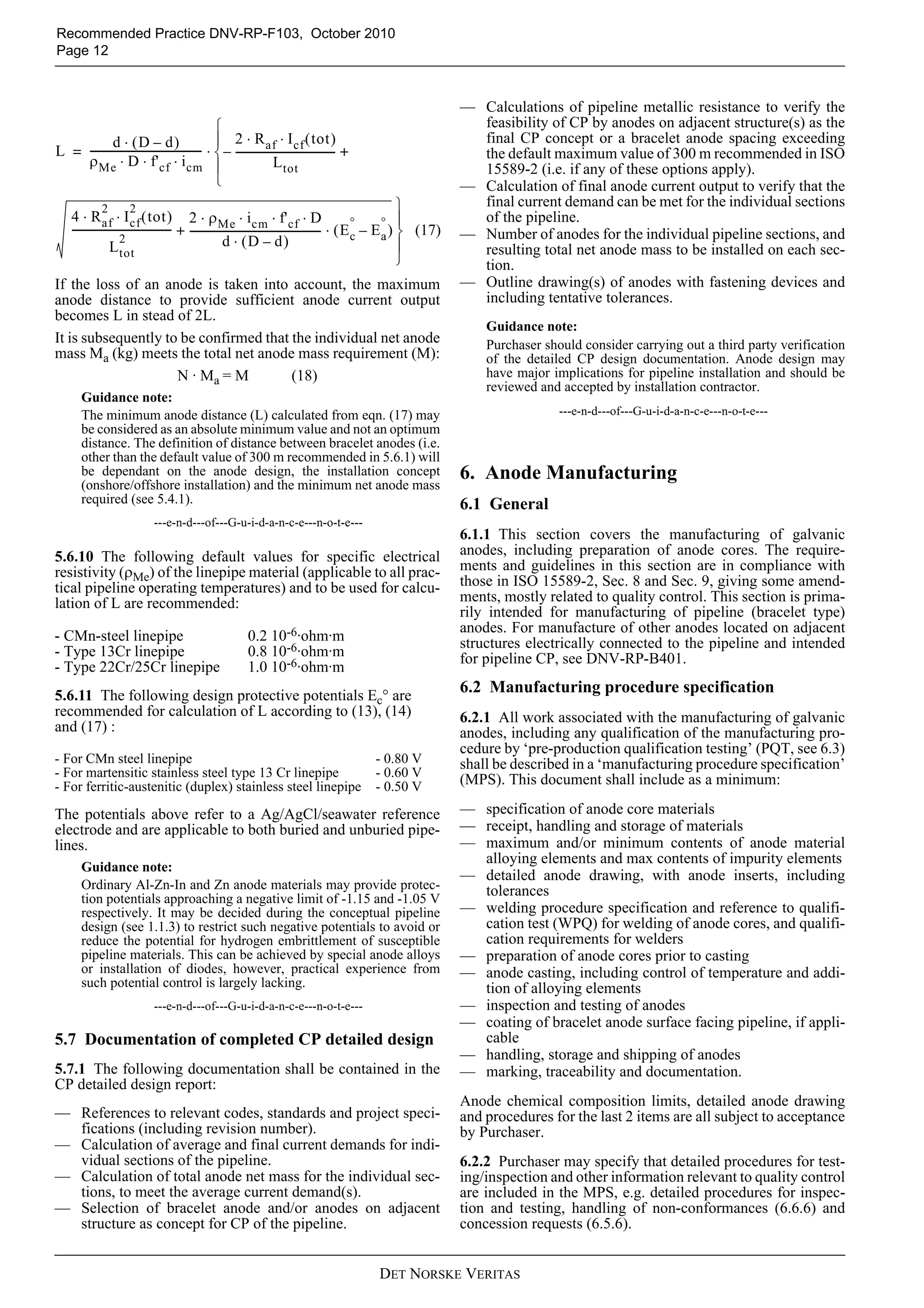
This document provides guidance on the cathodic protection of submarine pipelines by galvanic anodes. It covers topics such as calculating cathodic protection current demand, sizing anodes to meet the demand, anode manufacturing requirements, anode installation procedures, and documentation. The guidance is general but allows for customization to project specifics or regulatory requirements. The objective is to ensure cathodic protection systems are adequately designed and installed to protect submarine pipelines from corrosion.
This document provides the October 2007 version of DNV-OS-F101, which establishes standards and requirements for submarine pipeline systems. It has been amended since the original October 2007 publication. The document outlines objectives, scope, references, definitions, and provides standards for design loads, functional loads, environmental loads, accidental loads, and material selection for submarine pipeline systems. It aims to safeguard life, property, and the environment.
This document provides guidelines for designing submarine pipelines against global buckling due to high temperatures and pressures. It covers three buckling scenarios: 1) Exposed pipelines on even seabed that may buckle laterally, 2) Exposed pipelines on uneven seabed that may buckle vertically and laterally, and 3) Buried pipelines that may buckle vertically. Design procedures are given to either restrain pipelines to prevent buckling, or allow controlled buckling. Criteria ensure integrity against failure modes like local buckling or fracture. The guidelines are based on extensive analyses but special cases require critical evaluation.
This document provides guidance on non-intrusive inspection (NII) of pressure vessels and pipelines as an alternative to internal visual inspection (IVI). It discusses determining when NII is appropriate based on an integrity review considering the equipment profile, risk assessments, structural assessments, and operational experience. The document outlines the decision process for selecting and planning NII methods, evaluating results, and documentation requirements. The objective is to provide a consistent approach to justify and implement NII to reduce costs and hazards compared to IVI while still obtaining necessary information to ensure safe operation.
This document provides recommendations for assessing fatigue damage in risers. It outlines procedures for fatigue analysis using S-N curves and global fatigue analysis. Methods are presented for assessing vortex-induced vibration fatigue damage and combining fatigue damage from different sources. The document recommends design fatigue factors and procedures for reassessing and extending fatigue life based on inspections.
This document provides guidance on designing structures to withstand accidental loads from ship collisions, dropped objects, fires, and explosions. It discusses design philosophies, analysis considerations, and recommended force-deformation relationships for assessing the strength of structural components under different accidental load scenarios. Key aspects covered include dissipation of impact energy, strength of connections, ductility limits of materials, and modeling approaches for stiffened panels subjected to explosions. The document aims to help designers evaluate the ability of structures to resist accidental loads without catastrophic failure.
This document provides a recommended practice for risk-based inspection of offshore topsides static mechanical equipment. It outlines a risk-based approach to integrity management and maintenance planning, with the goal of prioritizing inspections based on probability and consequence of failure. The document describes methods for quantifying probability of failure through modeling of degradation mechanisms like corrosion, and for estimating risk based on probability and consequence of failure. It provides detail on degradation mechanisms for various materials and examples of modeling steps. The recommended working process involves gathering input data, screening assessments, detailed assessments, planning inspections, and evaluation.
This document provides guidance on structural design of self-elevating units. It covers environmental conditions including waves, current, wind, and water depth that should be considered in design. Wave conditions are characterized through significant wave height, peak period, and directional spreading. Current profiles vary with depth and are typically highest near the sea surface. Wind speed increases with height above the sea surface. Water depth and bottom conditions like soil properties also impact structural design.
This document provides standards for the certification of offshore containers. It outlines approval and certification procedures, requirements for materials, design, production, marking, lifting sets, periodic inspection and repairs. The main changes from the previous version include revisions to requirements for stainless steel, top protrusions, driving ramps, welding standards, and lifting set certification. Existing offshore containers certified under previous versions generally comply, though some may need to address stricter requirements for top protrusions. Containers certified under this standard will comply with international regulations and other relevant standards.
This document presents a framework for assessing the reliability of subsea production systems in Arctic environments. It aims to demonstrate that such systems can operate safely and profitably in the Arctic. The framework applies reliability modeling techniques to build an accurate model of a hypothetical subsea production system. It then uses the model to determine appropriate maintenance strategies as the system ages. A case study applies the framework to analyze the reliability of key components like valves, manifolds, and flowlines. The results indicate the framework can identify hazards and inform maintenance scheduling to improve safety while operating in the Arctic. The document concludes the framework provides an objective methodology for balancing safety, availability and maintenance of subsea infrastructure in the challenging Arctic conditions.
This document provides guidance on water treatment processes and systems. It discusses various preliminary treatment processes like screens and sand traps that are used to remove debris from source water. The main water treatment processes covered include aeration, coagulation, flocculation, sedimentation, filtration, disinfection, and other specialized processes. The document also provides design criteria for water treatment systems and guidance on measurement and control, chemicals used, and management of treatment plant wastes.
This document outlines standards for certification of lifting appliances by Det Norske Veritas (DNV). It addresses objectives, principles, application, definitions, services, certification procedures, and types of services provided. DNV undertakes classification, certification and other verification services related to quality, safety and environmental protection of various industries including lifting appliances. The document establishes requirements that form the basis for issuing certificates and declarations of conformity by DNV.
This document provides standards for general civil construction projects for Watercare. It outlines requirements for various civil construction activities including: site works, earthworks, pipe laying, concrete works, painting, demolition, masonry, plumbing, carpentry, metal roofing, polymer chambers, and testing. The document underwent minor revisions in version 1.1 including updates to referenced standards, requirements for tracer wire installation and HDD works, clarification of tolerances for pipe laying, and expanded tables for pressure testing.
The document is a final report from Group 72 for a speedboat to tugboat design challenge. It includes sections on constraints and specifications, concept generation, design choice, construction, testing and redesign. The group's design choice was to make the speedboat interchangeable with a tugboat configuration by adding a larger propeller with 4 blades of decreased pitch to increase thrust for tugging. Their goals were to improve battery life, stability, maneuverability, and tugging ability while staying within budget. They developed concepts like adding a second propeller, modifying the propeller blade angle, and protecting components from overheating or water damage. Their final design incorporated a 4-bladed propeller to increase thrust for tugboat functionality without significant
This discussion paper on Energy Well Integrity focuses on typical onshore unconventional oil or gas wells, which are generally similar to wells used for conventional oil or coal bed methane production. The major topics covered in this paper are well design, construction, use and abandonment. Issues of cementing practices and gas migration pathways are given special emphasis because they are key aspects in establishing and understanding well integrity.
This document provides rules for piping systems classification by Det Norske Veritas (DNV). It contains 7 sections that cover general requirements, materials, design principles, ship piping systems, machinery piping systems, pipes and related components, and manufacture/testing. The contents page lists the topics covered in each section. This document establishes standards for piping system classification by DNV for ships and offshore structures.
This specification provides requirements for shotcrete construction, including both wet-mix and dry-mix shotcrete. It establishes standards for materials, proportioning, testing, and application of shotcrete. The specification covers cement, aggregates, reinforcement, admixtures, mixing, surface preparation, application, finishing, curing, and tolerances for shotcrete work.
This document provides guidelines for cathodic protection (CP) design using galvanic anodes, and specifications for the manufacture and installation of such anodes for permanently installed offshore structures. It covers conceptual and detailed CP design procedures, calculation methods, parameters for galvanic anode material selection and sizing. Guidelines are also provided for qualification testing of anode materials and documentation of CP design, anode manufacture and installation.
This document presents the Certified Tester Foundation Level Syllabus. It covers the fundamentals of software testing including testing throughout the software life cycle, static testing techniques, test design techniques, test management, tool support for testing, and references. The syllabus is intended for anyone involved in software testing to prepare for the Foundation Level certification exam. It defines the learning objectives, exam format, and provides history and background information on the certification in the appendices.
The document is a chapter from the Department of Energy Fundamentals Handbook on Mechanical Science. It provides an overview of diesel engine fundamentals, including:
- A brief history of diesel engines and an introduction to their operating principles.
- Explanations of the basic components and cycles of 2-cycle and 4-cycle diesel engines.
- Descriptions of engine governors, fuel injectors, and protective features commonly used in diesel engines.
The chapter aims to give readers a foundational understanding of diesel engine operation to facilitate the safe and reliable operation of mechanical systems in DOE nuclear facilities.
This document provides an overview and summary of key information from the Offshore Standard DNV-OS-D301 Fire Protection document:
- It establishes technical provisions for passive and active fire protection systems on offshore facilities, including requirements for fire resistance of structures, ventilation ducts, penetrations, and protection of accommodation spaces.
- It outlines requirements for active fire protection in specific areas like production/processing areas, drilling areas, accommodation spaces, and machinery spaces. It also addresses storage of gas cylinders.
- Fire fighting systems are covered, including water pumps, mains, deluge systems, sprinklers, hydrants, monitors, and other portable equipment.
- Fire and gas detection systems must be
This document provides guidance on sequencing batch reactor (SBR) design and operation. It was developed by the New England Interstate Water Pollution Control Commission based on a literature review and visits to five SBR facilities. The document aims to highlight design and operational enhancements that can improve wastewater treatment performance. It is intended to assist municipalities, engineers, regulators and operators working with SBR systems.
This document discusses various photographic techniques to create different visual effects and provides examples of how each effect was achieved through specific photo compositions. It describes taking photos of a Barcelona shirt against a black and white background to draw attention to color; arranging backpacks in a line to lead the viewer's eye; capturing someone from a low angle to make them seem larger; shooting a watch in low light for contrast; blurring computers except one for a perspective effect; taking close-up photos; and combining a peach photo within other images to extend its context.
The document summarizes the history and future of network neutrality. It discusses how the debate over network neutrality began in the late 1990s and has continued to grow in importance. It also explores how network neutrality has been addressed through legislation and regulation in both the US and Europe. Finally, it explains that economics and human rights will continue to play a role in shaping the future of network neutrality policy.
Durham dads and male carers into museumsRob McIver
This document summarizes a 6-week course for dads and male caregivers that took place in Durham, England. The course involved visits to three local museums - Preston Hall, Shildon Locomotion, and Hartlepool Maritime Museum. During the visits, the groups read stories and did educational activities to take home. They also wrote weekly summaries about their experiences. The course was a partnership between local museums, family learning programs, and nurseries. It was later adapted for groups in Peterlee and Shildon that involved additional community partners like a soccer club and museum. A separate women-only course was also requested.
Think Together Talk Together – Lorna Chappell and Linda Bankier
Case study of a Berwick Children’s Centre Family Learning Course, focusing on developing family communication skills through museum objects.
This document outlines the shots, audio, actions, locations and transitions for 23 scenes in a film. It describes scenes such as a character looking in a mirror, sitting alone at a table in the kitchen, running in a park, and locking a door. The scenes reference emotions like desperation, frustration and determination and include dialogue, ambient sounds, music and transitions between shots.
On Your Soap Box -
Overview of a Renaissance NE funded project at Woodhorn Museum to develop an archive based session for secondary schools in South Northumberland. The session focuses on mining communities and includes investigation of archive material, Q&A sessions with ex-miners, and debate exploring pro and anti viewpoints of the 1984 miners' strike.
Public policy and online social networks: The trillion dollar zombie questionChris Marsden
26th Human Behaviour and the Evolution of Society conference
Workshop on Internet and Evolution of Society
Prof. Chris Marsden
University of Sussex School of Law
The document discusses recent education reforms in England, including the establishment of academies, free schools, and teaching schools. It also covers the Wolf Review of vocational education, the English Baccalaureate performance measure, and the ongoing review of the National Curriculum. The key dates for the National Curriculum review are the availability of new programs of study in core subjects from September 2012 and for all subjects from September 2013, becoming statutory in September 2014.
#IFCLA2014 keynote 'Open internet and Open access to law'Chris Marsden
Net neutrality has evolved in the past 4 months from a regulatory edict that was overcome by the US Appeal Court 14 January 14 decision in Verizon v. FCC 740 F.3d 623 (2014), to a strong European law passed at First Reading by the outgoing Parliament on 3 April 2014. Chris Marsden is author of the first legal research treatise on the subject Net Neutrality: Towards a Co-Regulatory Solution (January 2010, 2nd edition due 2016) and advisor to several governments and international organisations on net neutrality. He will explain what is in the new European law, contrast it with the FCC regulatory proceedings and case law, and identify a solution to the legislative and regulatory logjams on both sides of the Atlantic. The solution needs to both satisfy consumer advocates that access to the open Internet will constantly increase in quality, as well as satisfying service provider demands for adequate incentives to invest in high-speed lanes, known as ‘Specialised Services’. He will also speak about open access to the law. There is a strong connection between open access to the Internet and to the law. Without an adequate Internet connection in the office, at home and on the move, it does not matter how good a legal app is. Marsden will analyse the increasing tendency towards providing wider access to legislation, case law and commentary by governments, publishers and law firms. There are several European projects funded by the European Commission DG Justice such as www.openlaws.eu and EUCases, as well as national projects such as #goodlaw and legislation.gov.uk, that are making use of the Internet to provide a much richer experience in ‘mashing up’ existing databases for lawyers to tailor to their (and their clients’) needs. His analysis of open access to law is based on his forthcoming article in Computers & Law, and forms part of a two-year ongoing multinational research project.
Setting the scene - Adam Goldwater:
An update on what is happening in the formal learning sector and how the Renaissance Learning Team have been adapting their projects to meet the needs of Schools and Museums.
The document discusses search engine optimization (SEO) and provides definitions, explanations of key concepts, and recommendations. It defines SEO as improving traffic from organic search results by optimizing websites. The document outlines the SEO process, importance of keyword research, on-page optimization techniques, link building strategies, and analytics. It provides a checklist of elements websites should include for SEO and elements to avoid.
This talk was presented at Barcamp Blackpool 3 and introduced a basic teaching methodology before attendees then learnt and taught simple strategy games.
Visual thinking strategies in the early yearsRob McIver
Claire Greensit – Visual Thinking Strategy for Early Years
Case study of a VTS session with children from a Montessori Nursery at South Shields Museum & Art Gallery.
1) Propositional logic uses propositions that can be resolved as true or false and operators like NOT, AND, and OR to combine propositions.
2) Truth tables express all combinations of inputs to determine if a proposition is a tautology (always true) or contradiction (always false).
3) Equivalent propositions have the same truth values and De Morgan's laws can be used to transform expressions.
4) Some logical operators are "lazy" and short-circuit evaluation to improve efficiency by reducing unnecessary computations.
The document describes an art exhibition by four children named Alex, Harry, Olivia, and Macy. It shows photos they have taken of natural objects like balls, flowers, and spiders. It also shows photos of things they have made, such as handprints in playdough and rag rugs depicting nursery rhymes. The exhibition aims to showcase the children's journey in photography so far.
On bottom stability design of submarine pipelinesMintu Choudhury
This document provides guidance on the on-bottom stability design of submarine pipelines subjected to wave and current loading. It outlines three design methods: 1) a dynamic lateral stability analysis using time-domain simulation, 2) a generalized lateral stability method based on allowable displacement from a design wave spectrum, and 3) an absolute lateral static stability method ensuring stability for a single extreme wave oscillation. Safety factors are used to establish a target failure probability for lateral displacement as a serviceability limit state. Load combinations are defined for characteristic and temporary conditions based on return periods. Guidance is given on weight and resistance calculations, and a displacement design criterion of 10 pipe diameters is recommended.
This document provides an overview and recommendations for structural analysis of piping systems intended for offshore applications. It describes best practices for performing stress analysis, flexibility analysis, and fatigue analysis of topside and subsea piping to safeguard life, property, and the environment. The document references international codes and standards for piping design, and provides guidance on load considerations, calculations, documentation, and verification activities. Its aim is to describe a best practice approach for analyzing piping systems to ensure structural integrity and safety.
This document provides recommended practices for cathodic protection design. It has been amended since the original 2005 publication. The amendments include revisions to coating categories, design current densities, and additional requirements for anode manufacture and installation. It provides guidance on calculating cathodic protection requirements and the parameters to consider in design, such as design life, coatings, resistivity, and current demand. The document aims to give proven techniques and engineering practices for effective cathodic protection.
This document provides a recommended practice for designing cathodic protection systems using galvanic anodes for permanently installed offshore structures. It covers conceptual and detailed cathodic protection design, including specifications for manufacturing and installing galvanic anodes. The document is intended to facilitate cathodic protection design using aluminum or zinc-based galvanic anodes. While general, it provides guidance on incorporating project-specific requirements. It also excludes impressed current cathodic protection systems and cathodic protection of submarine pipelines from its scope.
The document provides recommendations for recertifying well control equipment used on the Norwegian Continental Shelf. It describes developing acceptance criteria based on original design specifications and standards. A recertification process for used equipment includes reviewing documentation, inspecting components, non-destructive testing, repair if needed, reassembly, testing, recoating, and issuing a recertification compliance certificate. Critical areas receive special focus during inspection and repair to ensure safety and integrity are maintained.
This document provides standards for general civil construction projects for Watercare. It outlines requirements for various civil construction activities including: site works, earthworks, pipe laying, concrete works, painting, demolition, masonry, plumbing, carpentry, metal roofing, polymer chambers, and testing. The document underwent minor revisions in version 1.1 including updates to referenced standards, requirements for tracer wire installation and HDD works, and clarification of tolerances for pipe laying. It is meant to be used in conjunction with Watercare's other cross-referenced standards and drawings.
This document provides guidance on the selection and use of subsea leak detection systems. It summarizes current industry experience with subsea leak detection technologies and methods. The document covers relevant regulations, field experience to date, available technologies and their characteristics. It also provides guidance on designing, installing, operating, calibrating and improving subsea leak detection systems to reliably detect hydrocarbon discharges to the environment.
This document provides the main changes between the October 2013 and August 2012 versions of DNV-OS-F101 Submarine Pipeline Systems. Some of the main changes include relaxing weld repair requirements and increasing installation speed by removing excessive conservatism related to fracture assessment of girth welds in Appendix A. Other changes include clarifying language around positive tolerances, minimum wall thickness requirements, and pressure test accuracy. The acknowledgement section recognizes commenting companies that improved the quality and content of the standard through their feedback.
As 4822 2008 external field joint coatings for steel pipelinestoddfly
This document provides standards for external field joint coatings applied to steel pipelines. It specifies requirements for selecting coatings, applicator obligations, surface preparation, application, inspection, testing, repair and safety. The standards cover petrolatum or polymeric tape coatings, heat-shrinkable coatings, fusion-bonded epoxy powder coatings, and liquid applied coatings. Appendices provide additional guidelines for purchasing, demonstrating compliance, and testing methods.
Material science, vol 1 of 2 us doe (1993) wwDiep Phan Hoang
This document provides an overview of the structure of metals, including:
- Atomic bonding and how it leads to ordered crystal structures in metals
- Common crystal lattice structures such as body-centered cubic and face-centered cubic
- Grain structure and boundaries in polycrystalline metals
- Polymorphism and how metals can exist in different crystalline phases
- Alloys and how adding alloying elements changes metal properties
- Common imperfections in metal structures such as vacancies, dislocations, and inclusions
This document provides guidelines for assessing erosive wear in oil and gas piping systems and injection systems. It gives limits for fluid parameters and materials that will not result in erosive wear, and provides a procedure for calculating erosive wear for fluids containing sand particles. The guidelines cover typical pipe components like straight pipes, bends, tees, and reducers. It also discusses dimensioning of pipes, erosion monitoring and mitigation. A software program is available to help with the erosive wear calculations.
This document provides an overview and summary of DNV-OS-A101, an offshore standard covering safety principles and arrangements for offshore units and installations. The standard addresses design principles and accidental loads, area arrangement, hazardous area classification, emergency shutdown systems, escape and communication, and special provisions for different types of offshore units. It defines objectives to provide an internationally acceptable safety standard and guidelines for designers, suppliers, owners and regulators. The standard is applicable to all mobile offshore units and fixed offshore installations but does not cover helicopter decks. It is intended for general worldwide application while also complying with any governmental legislation for a specific unit or location.
This document provides guidance on non-intrusive inspection (NII) of pressure vessels and related equipment as an alternative to internal visual inspection (IVI). It discusses determining when NII is appropriate based on an integrity review considering the equipment profile, risk assessments, structural assessment, and operational experience. The document outlines a decision process to screen for NII suitability and provides high-level guidance. It aims to help inspection planners by bringing together existing guidance and standards to plan, justify, implement, and evaluate NII in a consistent manner.
This technical specification provides guidelines for the design, installation, testing and maintenance of main earthing systems in substations. It covers the function and features of earthing systems, safety criteria to protect against electric shock, design considerations such as soil resistivity and fault currents, installation of conductors and electrodes, testing of the system, and maintenance. The document aims to help engineers properly earth metalwork at substations to ensure safety and reliability of supply.
Eurovent rec01 12 - sources of error in aerodynamic system, version 2011.03 1...Januário Esteves
This document discusses sources of error in calculating aerodynamic system resistance and acoustic performance. It notes that system resistance is often not truly proportional to flow rate squared due to Reynolds number effects in transitional flow regimes. Boundary layers can cause loss coefficients of duct fittings to vary significantly from assumed values. Upstream flow conditions like swirl or distorted velocity profiles also impact downstream losses. Differences between planned and actual installations can further undermine resistance calculations.
This document provides an overview of the bridge design process used by Main Roads Western Australia. It describes the six main stages of design: pre-design activities, preliminary design, final design, drawing preparation, contract documentation preparation, and providing design advice during construction. For each stage, it provides brief details on the key tasks and outputs. It emphasizes that the design process is sequential but stages often overlap. The document establishes the Structures Engineering Design Manual as the guide for how bridge design should be carried out to meet Main Roads' requirements.
The Variable Area flowmeter is an instrument for metering the flowrate of liquids and gases in a pipeline. It includes a vertically oriented conical tube, whose diameter is larg- er at the top than at the bottom, through which the fluid flows upward and in which a vertically moving float is positioned.
Guidelines for NDT of GRP pipe systems and tanksOsama Lari
This document provides guidelines for non-destructive testing and examination of glass-reinforced plastic pipe systems and tanks used in the Norwegian oil and gas industry. It summarizes defect types that should be inspected for, recommended non-destructive testing methods, and acceptance criteria. The guidelines are intended to standardize inspection practices and provide clarity on defect acceptance, which will help reduce costs associated with overconservative or nonconservative responses to defects found during inspection. The document provides information on inspection objectives, strategies and responsibilities at different stages of the product lifecycle from manufacture to operation.
The document provides an overview of engineering prints and drawings, including:
- The typical components of drawings such as the title block, grid system, and revision block.
- The main categories of drawings like piping and instrumentation diagrams, electrical schematics, and fabrication drawings.
- Views and perspectives commonly used in drawings such as orthographic, isometric, and exploded views.
This document is the Australian/New Zealand Standard for cellulose-cement flat sheets. It specifies requirements and test methods for fiber cement flat sheets intended for external or internal use. The standard classifies sheets as either Type A for external use or Type B for internal or protected external use. It defines acceptance criteria for dimensional tolerances, bending strength, water permeability, frost resistance, and other mechanical and physical properties. Test methods are provided for verifying that sheets meet the requirements.
3. Recommended Practice DNV-RP-F103, October 2010
Changes – Page 3
CHANGES
• General • Main changes
As of October 2010 all DNV service documents are primarily Since the previous edition (October 2003), this document has
published electronically. been amended, most recently in April 2008. All changes have
been incorporated and a new date (October 2010) has been
In order to ensure a practical transition from the “print” scheme given as explained under “General”.
to the “electronic” scheme, all documents having incorporated
amendments and corrections more recent than the date of the
latest printed issue, have been given the date October 2010.
An overview of DNV service documents, their update status
and historical “amendments and corrections” may be found
through http://www.dnv.com/resources/rules_standards/.
DET NORSKE VERITAS
4. Recommended Practice DNV-RP-F103, October 2010
Page 4 – Contents
CONTENTS
1. GENERAL .............................................................. 5 meet final current demand................................... 10
1.1 Introduction ............................................................. 5 5.6 Distribution of anodes .......................................... 10
1.2 Scope ........................................................................ 5 5.7 Documentation of completed CP
1.3 Objectives and use................................................... 6 detailed design ....................................................... 12
1.4 Structure of document ............................................ 6 6. ANODE MANUFACTURING ........................... 12
1.5 Relation to DNV-OS-F101 and other DNV 6.1 General................................................................... 12
documents on pipeline corrosion control .............. 6
6.2 Manufacturing procedure specification ............. 12
2. REFERENCES....................................................... 7 6.3 Pre-production qualification testing (PQT) ....... 13
2.1 DNV (Det Norske Veritas)...................................... 7 6.4 Quality control of production .............................. 13
2.2 EN (European Standards) ...................................... 7 6.5 Materials and casting ........................................... 13
2.3 ISO (International Organisation for 6.6 Inspection and testing of anodes.......................... 13
Standardization)...................................................... 7
6.7 Documentation and marking ............................... 14
3. TERMINOLOGY AND DEFINITIONS ............. 7 6.8 Handling, storage and shipping of anodes.......... 14
4. ABBREVIATIONS AND SYMBOLS .................. 7 7. ANODE INSTALLATION ................................ 14
4.1 Abbreviations .......................................................... 7 7.1 Design of anode attachment ................................. 14
4.2 Symbols for CP design parameters ....................... 7 7.2 Installation procedure specification.................... 14
5. CATHODIC PROTECTION DETAILED 7.3 Pre-production qualification testing (PQT) ....... 15
DESIGN .................................................................. 8 7.4 Quality control during production...................... 15
5.1 General ..................................................................... 8
7.5 Receipt and handling of anodes and materials for
5.2 Calculation of mean current demand for installation ............................................................. 15
cathodic protection.................................................. 8
7.6 Anode installation ................................................. 15
5.3 Calculation of Final Current Demand for
Cathodic Protection ................................................ 9 7.7 Inspection and testing of anode installation ....... 15
5.4 Calculation of total anode net mass to 7.8 Documentation ...................................................... 15
meet mean current demand .................................. 9 8. ANNEX 1 RECOMMENDATIONS FOR
5.5 Calculation of total anode current output to COATING BREAKDOWN FACTORS ............ 16
DET NORSKE VERITAS
5. Recommended Practice DNV-RP-F103, October 2010
Page 5
1. General the requirements and recommendations are general, the docu-
ment contains advice on how amendments can be made to
1.1 Introduction include project specific requirements. The document can also
easily be amended to include requirements/guidelines by a reg-
1.1.1 Submarine pipelines are designed with an external coat- ulating authority, or to reflect the pipeline operator’s general
ing as the primary system for corrosion control. Still, a philosophy on pipeline corrosion control.
cathodic protection (CP) system is normally provided as a
back-up to account for any deficiency in the coating system. Guidance note:
Such deficiencies may include holidays during coating manu- It is recommended that any additional conservatism is introduced
facturing, damage to the coating during transportation and by use of a “design factor” rather than modification of one or
installation of coated linepipe, and mechanical damage or more of the many design parameters used for CP calculations.
other coating degradation during operation of the pipeline. In For example, it may be specified that the design life shall be
based on the maximum estimated lifetime of the pipeline multi-
defining the required capacity of the CP system, the design of plied with some constant larger than 1 (one).
the pipeline coating system is the primary factor.
Guidance note: ---e-n-d---of---G-u-i-d-a-n-c-e---n-o-t-e---
Pipeline coatings may have other objectives in addition to corro-
sion control, including mechanical protection, thermal insulation 1.2.2 The document covers the detailed design of CP for sub-
and/or anti-buoyancy. In its widest sense, the term “pipeline marine pipeline systems (see 1.3.1) using galvanic anodes,
coating” includes “linepipe coating” (or “factory coating”) either Al - or Zn -based, and the manufacturing and installation
applied on individual pipe joints in a factory, “field joint coating” of such anodes. For CP of subsea manifold templates, riser
(FJC) and “coating field repairs” (CFR). In addition to the design
of the coating system, the quality control of its application is bases and other subsea structures where components of a pipe-
essential for its performance and thus also for CP design. line system are electrically connected to major surfaces of
structural C-steel, use of DNV-RP-B401 is recommended for
---e-n-d---of---G-u-i-d-a-n-c-e---n-o-t-e--- CP design (see 1.5.3). For conceptual CP design, Sec.5 is
applicable to preliminary calculations of the anode net mass
1.1.2 Cathodic protection of pipelines can be achieved using and anode distribution. This RP is based on the sections in ISO
galvanic (or “sacrificial”) anodes, or impressed current from 15589-2 that are applicable (see 1.3.1). For compliance with
rectifiers. For submarine pipelines, galvanic anode systems are the general philosophy in DNV-OS-F101, primarily with
most commonly applied. Such systems have traditionally been respect to procedures for quality control, or for the purpose of
designed as self-contained systems with all anodes installed clarification and guidance, some amendments are given. This
directly on the pipeline itself (bracelet type anodes). However, RP further contains some formula for calculation of CP protec-
the CP design in this document (as in ISO 15589-2) allows for tive range from adjacent structures and minimum distance
CP by anodes installed on adjacent structures electrically con- between pipeline anodes that are not included in the ISO stand-
nected to the pipeline such as platform sub-structures, subsea ard. Default values for galvanic anode performance and design
templates and riser bases. current densities that do not require any special qualification or
For pipelines in CRA's susceptible to hydrogen induced stress field testing are also recommended.
cracking (HISC) by CP, this concept has the main advantage
that the installation of anodes on the pipeline itself can be fully 1.2.3 By referring to specific pipeline coating systems for
avoided for shorter lines. linepipe, field joints and field repairs in DNV-RP-F102 and
DNV-RP-F106, and implementing the detailed requirements
Guidance note: for the quality control of their manufacturing as defined in
Apparently all failures of CRA pipelines due to HISC have been these documents, specific design parameters for calculation of
related to the welding of anodes to the pipeline causing stress current demands for CP are recommended in this RP. This is
concentrations, susceptible microstructure and defect coating. to enable a CP design without any arbitrary allowance for
The concept of installing anodes on adjacent structures also has
the advantage that the complete anode surfaces are exposed to deficiencies associated with the design and quality control of
seawater, increasing the anode electrochemical performance and such coatings, reducing the need for excessive conservatism in
the anode current output compared to those for anodes partly or the design. In this RP, and contrary to ISO 15589-2, the current
fully covered by seabed sediments. Moreover, the potential for demands for cathodic protection are calculated for specific
damage to the pipeline coating during installation is reduced. combinations of linepipe and field joint coating.
---e-n-d---of---G-u-i-d-a-n-c-e---n-o-t-e--- Guidance note:
In case certain deviations from the requirements to coating
1.1.3 The design of pipeline CP systems is mostly carried out design and/or quality control of manufacturing in DNV-RP-F106
in two steps; conceptual and detailed CP design. The ‘concep- and DNV-RP-F102 are identified, the CP design parameters
tual CP design’ will typically include selection of anode mate- associated with pipeline coatings in this document (i.e. “coating
rial, tentative net mass and dimensions of anodes, and concept breakdown factors”) may still be applicable. However, the user
for fastening of anodes. The conceptual design shall further of this document should then carefully assess the significance of
take into account potential detrimental effects of cathodic pro- any such deviations.
tection such as the pipeline materials’ intrinsic susceptibility to ---e-n-d---of---G-u-i-d-a-n-c-e---n-o-t-e---
hydrogen embrittlement by CP and the magnitude of local
stresses induced during installation, commissioning and oper-
ation of the pipeline that may lead to damage by HISC. For this 1.2.4 Full conceptual design of CP (see 1.1.3 and 1.2.2),
conceptual CP design, reference is made to the applicable sec- detailed design of impressed current CP systems, testing of
tions of DNV-OS-F101 and ISO 15589-2 (see 1.3.1). During galvanic anode material for the purpose of either qualification
the ‘detailed CP design’ (i.e. as covered in this document), the or quality control, and the operation of pipeline CP systems are
final net anode mass and dimensions of anodes, and their dis- not addressed in this document. For these items, reference is
tribution on the pipeline are defined. made to the general guidelines in DNV-OS-F101 and the more
detailed recommendations in ISO 15589-1, -2.
1.2 Scope
1.2.5 Although considerations related to safety and environ-
1.2.1 This Recommended Practice (RP) has been prepared to mental hazards associated with galvanic anode manufacturing
facilitate the execution of detailed CP design and the specifica- and installation are of great importance, such are never-the-
tion of galvanic anode manufacturing and installation. While less beyond the scope of this document.
DET NORSKE VERITAS
6. Recommended Practice DNV-RP-F103, October 2010
Page 6
1.3 Objectives and use dummy pipe sample (6.6.3)
— any specific requirements to Contractor’s management of
1.3.1 This RP complies with the requirements, recommenda- non-conformities and concession requests (6.6.7)
tions and guidelines in the applicable sections of ISO 15589-2. — retaining of anode material specimens (6.6.1)
It is applicable to ‘submarine pipeline systems’ as defined in — requirements to marking of anodes (6.7)
DNV-OS-F101, except risers above LAT for which cathodic — any specific requirements to handling, storage and ship-
protection is not efficient. For landfall sections protected by ping of anodes (6.8)
impressed current CP, reference is made to ISO 15589-1. — project specific requirements to final documentation,
1.3.2 The document has two major objectives. It may be used including schedule for supply (6.7).
as a guideline to pipeline operator’s or their contractor’s 1.3.7 For anode installation:
execution of detailed CP design, and to the specification of gal-
vanic anode manufacturing and installation. It may also be — anode installation design requirements, including anode
used as an attachment to an inquiry or purchase order specifi- drawing (tentative from CP conceptual or detailed design
cation for such work. If Purchaser has chosen to refer to this report, subsequently to be replaced by anode manufac-
RP in a purchase document, then Contractor should consider turer’s drawing)
all requirements in this document as mandatory (see Sec. 3), — design premises affecting anode installation, e.g. linepipe
unless superseded by amendments and deviations in the spe- dimensions, type of linepipe coating, pipeline installation
cific contract. concept
1.3.3 CP design, anode manufacture and anode installation are — location of anodes in relation to pipe ends and field joints
typically carried out by three different parties (all referred to as (7.6.3)
Contractor in this RP). The party issuing a contract (Purchaser) — any special requirements to qualification of anode installa-
may be either the installation contractor or Owner. For defini- tion (PQT), including e.g. verification of anode integrity
tion of contacting parties and associated terms, see Sec.3. during pipeline installation, application of in-fill and
repair of linepipe coating, as relevant (7.3)
1.3.4 Besides any reference to this document in a ‘purchase — any special requirements to quality control, e.g. use of IPS
document’ (see definition in Sec. 3), the information given in (7.2.1) and ‘daily log’ (7.4.2)
1.3.5 to 1.3.7 (intended as a check-list) shall be enclosed, as — any specific requirements to handling and storage of
applicable to the detailed CP design, anode manufacturing and anodes and materials for anode installation (7.5.3)
anode installation, respectively. — project specific requirements to final documentation,
including schedule for supply (7.8.3).
1.3.5 For cathodic protection detailed design:
1.4 Structure of document
— conceptual design report, if completed (5.1)
— relevant data from pipeline design basis, including e.g. 1.4.1 Requirements and recommendations for detailed
information on pipe material and dimensions, installation cathodic protection design, anode manufacturing and anode
conditions, internal fluid temperature, marine environ- installation are contained in Sec. 5, 6 and 7, respectively.
mental conditions, degree of burial or rock-dumping, line-
pipe and field joint coating design, design life (5.1) 1.5 Relation to DNV-OS-F101 and other DNV docu-
— requirements to documentation and verification, including ments on pipeline corrosion control
schedule for supply of documentation (5.7).
1.5.1 DNV-OS-F101 “Submarine Pipeline Systems”, Sec. 8,
1.3.6 For anode manufacturing: gives general guidelines to the conceptual and detailed design
of CP systems and contains some requirements and recom-
— anode material type (i.e. Al- or Zn-base) and any detailed mendations associated with anode manufacturing and installa-
requirements to chemical composition of anode material tion, in addition to pipeline coatings. Inspection of CP systems
(6.5.1) in operation is addressed in Sec. 10 of the same document.
— outline anode drawing (including anode cores) with tenta-
tive tolerances (5.7.1) 1.5.2 DNV-RP-F106 “Factory Applied Coatings for External
— project specific requirements to pre-production qualifica- Corrosion Control” and DNV-RP-F102 “Pipeline Field Joint
tion testing (PQT), including schedule for notification and Coating and Field Repair of Linepipe External Coatings” pro-
supply of documentation, number of anodes to be cast and vide detailed requirements to the manufacturing of pipeline
tested destructively for each casting mould (6.3) coatings.
— any special requirements to ‘manufacturing procedure
specification’ (MPS) (6.2.1) or ‘inspection and testing 1.5.3 DNV-RP-B401 “Cathodic Protection Design” (2005)
plan’ (ITP) (6.4.2) covers CP of other offshore structures than pipelines. How-
— requirements for frequency of destructive testing during ever, it is applicable for certain components of a pipeline sys-
production, and for verification of bracelet anode tab posi- tem like those installed on manifold templates and riser bases
tions by measurements and/or anode fit-up test on a (see 1.3.1).
DET NORSKE VERITAS
7. Recommended Practice DNV-RP-F103, October 2010
Page 7
2. References 4. Abbreviations and Symbols
2.1 DNV (Det Norske Veritas) 4.1 Abbreviations
CDS Coating Data Sheet
DNV-OS-F101 Submarine Pipeline Systems CFR Coating Field Repair
DNV-RP-B401 Cathodic Protection Design CP Cathodic Protection
DNV-RP-F106 Factory Applied External Pipeline Coatings for CR Concession Request
Corrosion Control CRA Corrosion Resistant Alloy
DNV-RP-F102 Pipeline Field Joint Coating and Field Repair of FJC Field Joint Coating
Linepipe External Coating
HISC Hydrogen Induced Stress Cracking
2.2 EN (European Standards) HV Vicker Hardness
IPS Installation Procedure Specification (see 7.2)
EN 10204 Metallic Products – Types of Inspection Docu- ITP Inspection and Testing Plan (see 6.4.2)
ments LAT Lowest Astronomical Tide
2.3 ISO (International Organisation for Standardi- LE Liquid Epoxy
zation) MIP Manufacturing and Inspection Plan (see 6.4.2)
MPS Manufacturing Procedure Specification (see 6.2)
ISO 8501-1 Preparation of Steel Substrate Before Application PE Polyethylene
of Paint and Related Products – Visual Assessment PP Polypropylene
of Surface Cleanliness. PVC Polyvinylchloride
– Part 1: Rust Grades and Preparation Grades of
Uncoated Steel Substrates and of Steel Substrates PQT Pre-Production Qualification Testing (see 6.3)
After Overall Removal of Previous Coatings. RP Recommended Practice
ISO 8503-2 Preparation of Steel Substrates Before Application SMYS Specified Minimum Yield Stress
of Paints and Related Products – Surface Rough- WPQ Welding Procedure Qualification
ness Characteristics of Blast-Cleaned Substrates. WPS Welding Procedure Specification
– Part 2: Method for the Grading of Surface Profile
of Abrasive Blast-Cleaned Steel 4.2 Symbols for CP design parameters
– Comparator Procedure
ISO 10474 Steel and Steel Products – Inspection Documents References within brackets refer to paragraphs in this docu-
ISO 10005 Quality Management – Guidelines for Quality
ment where the design parameters are defined.
Plans Ac (m²) surface area (5.2.1)
ISO 13847 Petroleum and Natural Gas Industries- Pipeline a constant (5.2.7)
Transportation Systems – Welding of Pipelines b constant (5.2.7)
ISO 15589-1 Petroleum and Natural Gas Industries- Cathodic D (m) linepipe outer diameter (5.6.4)
Protection of Pipeline Transportation Systems d (m) linepipe wall thickness (5.6.5)
– Part 1: Onshore Pipelines (see 1.3.1)
ISO 15589-2 Petroleum and Natural Gas Industries- Cathodic
Ea° (V) design closed circuit anode potential (5.5.1)
Protection of Pipeline Transportation Systems Ec°(V) design protective potential (5.5.1)
– Part 2: Offshore Pipelines (see 1.3.1) E'c (V) global protection potential (5.6.3)
ΔEA (V) electrolytic voltage drop (5.6.9)
ΔEMe (V) metallic voltage drop (5.6.3)
3. Terminology and Definitions ε (A·h/kg) anode electrochemical capacity (5.4.1)
fcm mean coating breakdown factor (5.2.5)
Owner party legally responsible for design, construction fcf final coating breakdown factor (5.3.2)
and operation of the pipeline
Purchaser party (Owner or main contractor) issuing inquiry or
f'cf mean final coating breakdown factor (5.6.4)
contract for engineering, manufacturing or installa- Iaf (A) final anode current output (5.5.1)
tion work, or nominated representative Ic (A) current demand (5.2.1)
Contractor party to whom the work has been contracted Icm (A) mean current demand (5.2.1)
shall indicates a mandatory requirement Icm (tot) (A) total mean current demand (5.2.9)
should indicates a preferred course of action Icf (A) final current demand (5.3.1)
may indicates a permissible course of action Icf (tot) (A) total final current demand (5.3.1)
agreed refers to a written arrangement between Purchaser icm (A/m²) design mean current density (5.2.3)
agreement and Contractor (e.g. as stated in a contract) L (m) length of pipeline to be protected from one
report and refers to an action by Contractor in writing anode (5.6.3)
notify
Ltot (m) length of pipeline section (5.6.9)
accepted refers to a confirmation by Purchaser in writing
acceptance M (kg) total net anode mass (5.4.1)
certificate refers to the confirmation of specified properties Ma (kg) individual net anode mass (5.6.9)
certified issued by Contractor or supplier of coating N number of anodes (5.5.3)
materials according to EN 10204:3.1.B, ISO RMe (ohm) metallic resistance (5.6.3)
10474:5.1-B or equivalent.
Raf (ohm) anode final resistance (5.5.1)
purchase refers to an inquiry /tender , or a purchase/contract
document(s) specification, as relevant r ratio: length of cutbacks (2 off) to linepipe
coating per pipe joint (5.6.4)
manufacture refers to work associated with anode manufactur-
manufacturing ing and installation, including qualification of a ρMe (ohm·m) resistivity of linepipe material (5.6.5)
MPS (i.e. PQT) and WPS tf (years) design life (5.2.6)
u anode utilisation factor (5.4.2)
DET NORSKE VERITAS
8. Recommended Practice DNV-RP-F103, October 2010
Page 8
5. Cathodic Protection Detailed Design bare metal surface exposed to the environment; i.e. seawater or
marine sediments (see Guidance Note to 5.2.4). “mean” refers
5.1 General to an average value for the design life.
5.1.1 The detailed design of a pipeline CP system is normally 5.2.4 Table 5.1 gives recommended mean design current
preceded by a conceptual design activity (see 1.1.3), during densities for buried and non-buried pipelines (or sections of a
which the type of CP system and type of galvanic anode pipeline) as a function of the fluid temperature but independent
material to be used (i.e. unless an impressed current CP system of depth. “Buried” refers to pipeline sections to be subjected to
was selected) have been defined. A concept for anode attach- trenching and backfilling. Pipelines (or pipeline sections) to be
ment will normally also be selected, considering requirements installed in very soft soil for which complete self-burial can be
for the integrity of anodes during pipeline installation and pro- demonstrated (e.g. by calculations) may also be considered as
vision of electrical connection of anode material to the pipeline. “buried”, however, sections for which incomplete self-burial is
If no CP conceptual report has been prepared, then the premises expected shall always be considered as “non-buried” for calcu-
and basic concepts for detailed CP design shall be defined by lation of current demand. Pipeline sections without trenching
Purchaser in some other reference document (see 5.1.3). This but covered by rock / gravel dumping may further be consid-
information shall be included in an inquiry (ref. 1.3.5) ered as “buried”. The design current densities in Table 5-1 are
applicable for pipelines with linepipe coating and FJC / CFR
5.1.2 The pipeline conceptual design will normally define the as defined in DNV-RP-F106 and DNV-RP-F102, respectively.
generic type of pipeline coatings to be utilised for linepipe and For any pipeline components or parts of pipelines designed
pipeline components, and for coating of field joints. Based on without such coatings, default values of 0.100 A/m2 and
this, it is common practice to carry out a preliminary calcula- 0.050 A/m2 are recommended for non-buried and buried
tion of current demands for cathodic protection and the associ- items, independent of surface temperature and depth. It is then
ated total net mass of anode material required, resulting in a presumed that any such areas constitute a minor surface area
preliminary sizing and distribution of individual anodes (see (maximum 2%) compared with the overall surface area (pipe
1.1.3). section) to be protected. For any larger surfaces, DNV-RP-
B401 is recommended for calculations of CP current demands.
5.1.3 In addition to the conceptual CP design report (if com- The design current densities in this paragraph are applicable to
pleted), the project design basis should contain all project spe- CRA as well as CMn-steel linepipe and ordinary C-steel.
cific input parameters for the execution of detailed CP design.
Purchaser should ensure that the valid revision of the design Table 5-1 Recommended design mean current densities
basis is available to Contractor during the design work. (in A/m2) as a function of internal fluid temperature
5.1.4 The design calculations in this section are in accordance Exposure Internal Fluid Temperature (°C)
with ANNEX A of ISO 15589-2, giving some amendments for Condition ≤ 50 >50 - 80 >80 - 120 >120
the purpose of clarification or to facilitate selection of CP Non-Buried*) 0.050 0.060 0.070 0.100
design parameters. (The above standard is sometimes referred Buried*) 0.020 0.025 0.030 0.040
to as “the ISO standard” or “the standard” in the text of this
RP). *) see definition in 5.2.4
5.1.5 All electrochemical potentials associated with CP in this Guidance note:
section refer to the Ag / AgCl / seawater reference electrode. The design current densities in Table 5-1 are applicable inde-
(The potential of this reference electrode is virtually equivalent pendent of geographical location and depth but should be consid-
to that of the standard calomel electrode). ered as minimum values. Based on special considerations, the
Owner/Purchaser may chose to specify higher design values than
5.2 Calculation of mean current demand for those in Table 5-1.
cathodic protection ---e-n-d---of---G-u-i-d-a-n-c-e---n-o-t-e---
5.2.1 For the detailed CP design, a pipeline should normally Guidance note:
be divided into sections based on variations in fluid and envi- The current demand associated with cathodic protection of pipe-
ronmental parameters (e.g. fluid temperature and burial condi- lines is related to “leakage” of current at pores and narrow cracks
tions) that affect the ‘current demand’ Ic for CP. or crevices in the coating, primarily in connection with field
The ‘mean current demand’, Icm (A) for a specific pipeline joints. Hence, there is no direct exposure of steel surfaces to sea-
‘surface area’ Ac is calculated from: water and the temperature at the metal / electrolyte interface is
close to that of the internal fluid temperature. The cathodic
Icm = Ac ⋅ fcm ⋅ icm (1) current is then primarily related to hydrogen evolution, even for
(fcm and icm are defined below) unburied pipeline sections, whilst reduction of dissolved oxygen
has a minor contribution to the cathodic reaction. As a conse-
5.2.2 In this RP, the surface area associated with field joint quence, seawater parameters affecting oxygen supply (e.g.
coating at girth welds shall be calculated separately and the dissolved content of oxygen and seawater flow), hydrostatic
associated current demand according to equation (1) is then pressure and seawater ambient temperature are less important.
The cathodic current is primarily determined by diffusion and
added to the current demand for the pipeline covered by line- migration processes in the pores and crevices and the electrolytic
pipe coating and for any pipeline components with other types resistivity. For pipelines operating above ambient seawater
of coating. temperature, the temperature of the internal fluid, having a major
Guidance note: effect on diffusion/migration processes and electrolytic conduc-
tivity, is the decisive factor for the current demand.
For CP calculations, a minimum cut-back length of 0.20 m
should be applied. As the surface area associated with field joints ---e-n-d---of---G-u-i-d-a-n-c-e---n-o-t-e---
is only a few percent of the total pipe area, it is not actually nec-
essary to subtract the FJC area when calculating the current
demand for surfaces with linepipe coating. 5.2.5 fcm in equation (1) is a dimensionless factor (≤1) termed
‘mean coating breakdown factor’, describing the assumed
---e-n-d---of---G-u-i-d-a-n-c-e---n-o-t-e--- capability of the coating to reduce the current demand for
cathodic protection. (See also Guidance Notes to 5.2.7, 5.3.1
5.2.3 In equation (1) above, icm is the ‘design mean current and 5.3.2). “mean” refers to an average value for the design
density’, i.e. the mean cathodic current density of an assumed life.
DET NORSKE VERITAS
9. Recommended Practice DNV-RP-F103, October 2010
Page 9
5.2.6 The mean coating breakdown factor fcm is given by the generic type of coating (e.g. fusion bonded epoxy) or purpose of
equation: coating (e.g. thermal insulation) and to (quote:) commonly
applied industry standards.
fcm = a + 0.5 ⋅ b ⋅ tf (2)
The constants recommended in Annex 1 are only applicable if the
where tf (years) is the ‘design life’. a and b are defined below. actual coating specifications are in general compliance with the
referred DNV RP's. However, for certain combinations of coat-
Guidance note: ing systems (e.g. asphalt and coal tar enamel plus FJC based on
The design life to be used for CP detailed design shall be defined tape or sleeves with infill), the CP system can readily be designed
by Purchaser and should be a conservative estimate of the maxi- so that the current demands of both standards are fulfilled
mum expected lifetime of the pipeline. Any significant period of (see also Guidance notes to 5.4.1 and 5.6.9).
time between installation and start of operation shall be included.
---e-n-d---of---G-u-i-d-a-n-c-e---n-o-t-e---
5.3 Calculation of Final Current Demand for
5.2.7 a and b in equation (2) are constants. Table A.1 and A.2 Cathodic Protection
in Annex 1 give recommendations for constants to be used for
specific combinations of linepipe coating and FJC systems as 5.3.1 The ‘total final current demand’, Icf(tot) (A) for a spe-
defined in DNV-RP-F106 and DNV-RP-F102, respectively, cific pipeline section is calculated by adding the contributions
and for the maximum operating temperatures indicated in the from coated linepipe, field joints and pipeline components cal-
tables. These constants further assume that any damage to the culated from:
linepipe coating is repaired (CFR) in accordance with DNV-
RP-F102 prior to installation, and that the compatibility of Icf = Ac ⋅ fcf ⋅ icm (3)
installation systems with the linepipe and FJC has been veri- as described in 5.2 above.
fied by testing or calculations. Furthermore, it is assumed that
Guidance note:
the pipeline is protected by weight coating, burial or rock /
gravel dumping as required to avoid damage in operation caus- The design “initial” and “final” current densities as defined in
ing significant exposure of bare metal. DNV-RP-B401 refer to the anticipated current demand (at a
fixed protection potential of - 0.80 V) for the initial polarisation
Guidance note: of a bare steel surface, and for re-polarisation of a bare steel sur-
The constant a defines the assumed initial capability of the coat- face that has become depolarised due to the mechanical removal
ing to reduce the current demand for cathodic protection, whilst of surface layers (calcareous deposits), respectively. For pipe-
the constant b defines the assumed degradation of this capability lines coated with the systems defined in DNV-RP-F106 and
over time (“coating breakdown”) although the coating may DNV-RP-F102, the requirement to such polarising capacity is
appear visually unaffected. The constants a and b defined in not considered relevant and icm is used in equation (3). This
Tables A.1 and A.2 are rough estimates based on practical expe- approach is applicable also to pipelines (or pipeline sections)
rience and engineering judgement. This is reflected by the accu- with minor areas (maximum 2%) coated with other types of coat-
racy of the numbers recommended. ing (see 5.2.8).
---e-n-d---of---G-u-i-d-a-n-c-e---n-o-t-e--- ---e-n-d---of---G-u-i-d-a-n-c-e---n-o-t-e---
5.2.8 For any pipeline components protected by “ordinary” 5.3.2 The ‘final coating breakdown factor’ fcf is given by the
marine coating systems based on e.g. liquid epoxy or poly- equation:
urethane (dry film thickness ≥ 150μm), default values of 0.10 fcf = a + b ⋅ tf (4)
and 0.03 are recommended for a and b respectively. These
default values further presume a surface cleanliness of using the a and b constants in Table A.1 and A.2 in Annex 1.
A/B Sa 2 1/2 and surface roughness grade Medium according Guidance note:
to ISO 8501-1 and ISO 8503-2, respectively. The current It is the coating breakdown factor used for CP design that in the
demand of surfaces without pipeline coatings as defined in main determines the magnitude of the calculated current demand.
DNV-RP-F106 and DNV-RP-F102 shall be calculated using Compared to this factor, the effect of variations of other design
the design current densitiy default values defined in 5.2.4. The parameters such as design current densities and those associated
use of such default values presumes that any such areas consti- with the anode performance is relatively small
tute a minor surface area (maximum 2%, see 5.2.4) compared (See also Guidance note to 5.2.9).
with the overall pipeline surface area. ---e-n-d---of---G-u-i-d-a-n-c-e---n-o-t-e---
5.2.9 Based on the design current densities and coating break-
down factors as defined above, the current demand contribu- 5.4 Calculation of total anode net mass to meet mean
tions from coated linepipe, field joints and any pipeline current demand
components with “ordinary” marine coating are calculated
individually according to equation (1) and then added to make 5.4.1 Using the calculated total mean current demand Icm
up the ‘total mean current demand’ Icm(tot) (A). (tot), the ‘total net anode mass’ M (kg) required is calculated
from:
Guidance note:
I cm ⋅ t f ⋅ 8760
ISO 15589-2 recommends constants a and b in eqn (2) for gen- M = -------------------------------- (5)
eral types of pipeline coating systems assuming that the reduc- u⋅ε
tion of current demand for CP (i.e. per surface area) is the same
for linepipe and FJC (quote: field joints having a quality equiva- where u (dimension less), is the anode ‘utilisation factor’ and
lent to factory-applied coatings). ε in (A·h/kg) is the ‘electrochemical capacity’ of the anode
This RP, however, refers to specific combinations of linepipe and material. (“8760” is the number of hours per year).
FJC coating and takes into account their relative surface area Guidance note:
(eqn. 9). The calculated FJC coating breakdown factor may then The total net anode mass calculated from eqn. (5) may be consid-
be 3-30 times higher than for the linepipe coating. For certain ered as an absolute minimum value. If a default anode distance
combinations of parent and linepipe coating, the calculated over- of 300 m is adopted (5.6.1), typical bracelet anode dimensions
all coating breakdown using the constants in Annex 1 may be sig- will normally give a significantly higher anode mass to be
nificantly lower than in the ISO standard. installed. Any excess anode mass installed can be utilised as a
This is justified by the specific requirements to coating design contingency in case the calculated current demand was underes-
and quality control of coating application in the referenced DNV- timated due to e.g. pipeline components not included in the cur-
RP-F102 and DNV-RP-F106; the ISO standard referring to the rent demand calculations, or unforeseen mechanical damage to
DET NORSKE VERITAS
10. Recommended Practice DNV-RP-F103, October 2010
Page 10
the coating during installation and/or operation, or if the design 5.5 Calculation of total anode current output to meet
life of the pipeline is extended. (For inclusion of contingency in final current demand
pipeline CP design, see Guidance note to 1.2.1).
---e-n-d---of---G-u-i-d-a-n-c-e---n-o-t-e--- 5.5.1 Based on the total net anode mass (M) for the pipeline or
pipeline section calculated from equation (5) and the pipeline
outer diameter (including coating), a tentative pipeline anode
5.4.2 The anode utilisation factor u (dimensionless) shall be dimension can be defined. The ‘final anode current output’ Iaf
selected according to ISO 15589-2, Sec. 7.4; i.e. maximum (A) of an anode (with tentative dimensions) at the end of its
0.80 for bracelet anodes, and maximum 0.90 for elongated design life shall be calculated in accordance with ISO 15589-
stand-off type of anodes placed on other subsea structures for 2, Annex A, Sec. A.7 using the equation
protection of the pipeline.
Guidance note: ( Ec ° – Ea ° )
I af = ---------------------------
- (6)
u depends on the anode core arrangement and for special anode R af
designs, the actual value may be smaller than the default values
defined above. Candidate anode manufacturers should be con- where Ea°(V) is the ‘design closed circuit anode potential’.
sulted in such cases. The design values in Table 4 of the ISO standard shall apply.
---e-n-d---of---G-u-i-d-a-n-c-e---n-o-t-e--- Ec° (V) in equation (6) is the ‘design protective potential’ of
the linepipe material to be protected (see 5.6.11) and Raf (ohm)
is the ‘final anode resistance’. Equation (6) assumes that the
5.4.3 According to ISO 15589-2, the anode material electro- metallic resistance in the pipeline is much smaller than the
chemical capacity (ε) used for CP design shall take into ‘anode electrolytic resistance’ Raf. This assumption is applica-
account the effect of the estimated anode current density ble to all types of pipelines with pipeline coatings as defined in
according to Sec. A.9 in Annex A of the standard. The ISO DNV-RP-F106 and DNV-RP-F102 and with a distance from
standard further requires that the use of data according to Table the anode of up to 300 m as a minimum.
4 shall be documented by long term testing according to Annex
B of the standard. It is recommended in this RP that if data for Guidance note:
Al-Zn-In anodes (meeting the compositional requirements in The design protective potential (Ec°) as defined in 5.6.11 is appli-
Table 5 of the ISO standard) at the applicable temperature and cable also when a more negative protection potential is aimed for
anode current density are not at hand, the data in Table 4 of the during operation of the pipeline. Hence, Iaf is calculated to ensure
ISO standard shall be used, multiplied by a design factor of 0.8 sufficient polarizing capacity of the CP system based on Raf and
using the design protective potential as a default value for defini-
(dimensionless). As an example, this will give 2,000 Ah/kg tion of the driving voltage.
and 1,600 Ah/kg for anodes exposed to seawater and marine
sediments, respectively, at anode surface temperatures up to ---e-n-d---of---G-u-i-d-a-n-c-e---n-o-t-e---
30°C. The data for zinc anode materials (meeting the compo-
sitional requirements in Table 6 of the ISO standard) in Table 5.5.2 The final anode resistance Raf in equation (6) shall be
4 of the standard are applicable also at low current densities. calculated according to Annex A, Sec. A.8 of ISO 15589-2.
The temperature limits for Al-Zn-In and Zn anodes in the ISO For pipelines defined as “non-buried” in 5.2.4, the ambient
standard (Table 4) shall apply, see 5.4.4 below. temperature seawater resistivity is applicable for calculation of
Guidance note: Raf. The seawater resistivity (annual average) may be esti-
Data on anode electrochemical efficiency from laboratory exam-
mated based on Fig. 1 in Annex A of the ISO standard. For bur-
inations will typically result in values close to the theoretical ied pipeline anodes, an actually measured soil resistivity
limit (e.g. >2,500 Ah/kg for Al-Zn-In material). This is due to the should be applied, corrected for any annual temperature varia-
relatively high anodic current densities that are utilized for test- tions. As an alternative, a default value of 1.5 ohm·m may be
ing. Such data shall not replace the recommended design values used.
for electrochemical capacity. The use of higher electrochemical
efficiency than the default values defined above should be justi- 5.5.3 From the final (individual) anode current output (Iaf),
fied by long term testing according to Annex B of the ISO stand- and the ‘total final current demand’ Icf(tot) for cathodic protec-
ard. tion of a pipeline section, the required number (N) of anodes
---e-n-d---of---G-u-i-d-a-n-c-e---n-o-t-e--- becomes
I cf ( tot )
5.4.4 For anodes on pipelines defined as “non-buried” for cal- N = -----------------
- (7)
I af
culation of current demand (see 5.2.4), the electrochemical
capacity for anodes “immersed in seawater at anode surface in accordance with Annex A, Sec. A.7 of the ISO standard.
temperature ≤30°C” as defined in Table 4 of the ISO standard This exercise may involve some adjustment(s) of the initially
are applicable (i.e. according to 5.4.3), also if the fluid temper- selected (tentative) anode dimensions and re-iterative calcula-
ature is higher than 30°C. For anodes on “buried” sections tions in order to meet the requirements for both total net anode
(5.2.4), the internal fluid temperature may be used as a con- mass M and ‘total final anode current output’ (N · Iaf).
servative estimate of the anode surface temperature. As an
alternative, the anode surface temperature may be estimated by 5.6 Distribution of anodes
heat transfer calculations taking into account any thermal insu-
lation applied between anode and steel surface, in addition to 5.6.1 In ISO 15589-2, Sec. 7.1 a default maximum anode dis-
environmental parameters. tance of 300 m is advised for pipeline CP design. It is pre-
sumed in the standard that this distance will ensure sufficient
Guidance note: anode current output in the event an adjacent anode is lost such
The use of Al-Zn-In or Zn based anode alloys for surface temper- that the actual anode distance becomes 600 m. For larger dis-
atures higher than 80°C and 50°C, respectively, shall be qualified tances than 300 m (i.e. by design), the effect of the metallic
by realistic long-term testing. However, it is recommended pri- resistance in the pipe wall shall be taken into account.
marily to avoid such temperatures by application of heat insula-
tion between anode and, pipe wall or by installing anodes freely Guidance note:
exposed to seawater whenever practical. Hence, cathodic protec- For medium and long distance export pipelines with concrete
tion of a relatively short “buried” section can readily be provided coating, the concept of using pre-installed anodes and with a
by adjacent anodes on “non-buried” sections. default maximum distance of 300 m is adequate for most pur-
poses (See Guidance note to 5.4.1). Except for very long design
---e-n-d---of---G-u-i-d-a-n-c-e---n-o-t-e--- lives (> 30 years), a typical bracelet anode size (i.e. convenient
DET NORSKE VERITAS
11. Recommended Practice DNV-RP-F103, October 2010
Page 11
for casting) will then give an installed anode net mass that 5.6.6 Assuming that the cathodic current is largely uniformly
exceeds the calculated required net anode mass. distributed on L, and inserting equation (9) and equation (11)
---e-n-d---of---G-u-i-d-a-n-c-e---n-o-t-e--- in equation (8):
5.6.2 According to this RP, short pipelines (<10-30 km
2
approximately depending on the design and operating condi- L ⋅ ρ Me ⋅ f' cf ⋅ i cm ⋅ D
tions) may be protected by installing anodes on subsea struc- ΔE Me = E c ° – E' c = -----------------------------------------------------
- (12)
tures located at the pipeline termination(s) and to which the 2 ⋅ d ⋅ (D – d)
pipeline is electrically connected. Examples of such structures
are subsea production templates, riser bases and platform sub- and L becomes
structures. Anodes (elongated type) may also be installed on a
dedicated structure (sledge) with a cable connection for elec-
trical continuity to the pipeline. Calculations of anode current 2 ⋅ ΔE Me ⋅ d ⋅ ( D – d )
output from such anode arrangements shall take into account L = ---------------------------------------------------
- (13)
the significance of a voltage drop in the cable connection and ρ Me ⋅ D ⋅ f' cf ⋅ i cm
any interaction between closely spaced anodes affecting their
electrolytic resistance (i.e. “anode resistance” according to
5.5.2). The above equation gives a simplified method to assess the
voltage drop associated with a cathodic current in a pipeline.
Guidance note:
Also the ISO 15589-2 encourages CP of short pipelines by 5.6.7 In case the cathodic current is expected to be unevenly
anodes located at each end of the pipeline. To calculate the pro- distributed along L, it may be assumed conservatively that all
tective length of such anodes, this standard recommends so- current enters at L such that
called attenuation calculations contained in an Annex A. These
formulas are fairly complicated and contain the pipe-to-electro-
lyte insulation resistance as the most critical parameter and
which (quote:) should be selected based on practical experience. ΔE Me ⋅ d ⋅ ( D – d )
This RP, however, offers a simplified approach with specifica- L = -------------------------------------------- (14)
tion of all required design parameters. ρ Me ⋅ D ⋅ f' cf ⋅ i cm
---e-n-d---of---G-u-i-d-a-n-c-e---n-o-t-e---
5.6.3 The length of a pipeline L (m) that can be protected by 5.6.8 For cathodic protection by anodes on coated subsea
anodes located on a secondary structure (with excess CP structures freely exposed to seawater, a design global protec-
capacity, see 5.6.8) is determined by the ‘global cathodic tion potential (E'c) of - 0.95 V is recommended as a reasonably
potential’ E'c (V) at this structure, the design protective poten- conservative default value. For structures with major areas in
tial Ec° (V) of the linepipe material and the ‘metallic voltage bare steel (e.g. platform sub-structures) - 0.90 V is recom-
drop’ ΔEMe (V) associated with the electrical current Icf in the mended as a default value.
pipeline and its ‘metallic resistance’ RMe (ohm). It follows Guidance note:
from Ohm’s law:
A pipeline CP design based on anodes located on adjacent struc-
ΔEMe = Ec° - E'c = RMe · Icf (8) tures must ensure that the CP systems of these structures are suf-
ficiently robust. Hence, towards the end of the life of a CP
5.6.4 The total cathodic current entering the pipe section of L system, the global protective level may decrease to values less
becomes: negative than those assumed above. For new structures, the CP
Icf = L · D · π · f'cf · icm (9) system can be designed with an additional conservatism (e.g.
extended CP design life). For an existing structure with marginal
where CP capacity, monitoring of the global protection potential and
ultimately retrofitting of anodes may be required. (Note also that
D (m) is the linepipe outer diameter even with dedicated pipeline anodes, a pipeline electrically con-
f'cf (dimensionless) is the ‘final coating breakdown factor’ cal- nected to structures with marginal CP may suffer premature
culated as a mean value for linepipe and field joint coating anode consumption and ultimately underprotection.)
according to ---e-n-d---of---G-u-i-d-a-n-c-e---n-o-t-e---
f'cf = fcf (linepipe) + r · fcf (FJC) (10)
where r is the ratio of the lengths of the cutbacks and the line- 5.6.9 If CP is to be provided by bracelet anodes, and the
pipe coating for the specific pipeline or pipeline section. default value of maximum 300 m according to 5.6.1 shall not
Guidance note:
apply, then the maximum distance between successive anodes
may be calculated using equation (17) below. For a pipeline
The length of cut-back refers to the corrosion protective coating. section with a length of Ltot (m) to be protected by N bracelet
For cutbacks with length < 0.20 m, a default minimum value of
0.20 m is recommended. With this default value, and for a pipe- anodes, the maximum distance between anodes becomes 2L:
line section with all joints of 12 m length approximately,
r = 0.033 and f'cf = fcf (linepipe) + 0.033 fcf (FJC).
L tot
---e-n-d---of---G-u-i-d-a-n-c-e---n-o-t-e--- 2L = --------
- (15)
N
5.6.5 The metallic resistance RMe is calculated from:
L may be calculated taking into account both the electrolytic
voltage drop ΔEA (V) and the metallic voltage drop ΔEMe for
L ⋅ ρ Me which the following relation applies:
R Me = --------------------------------
- (11)
π ⋅ d ⋅ (D – d) ΔEA + ΔEMe = Ec° - Ea° (16)
where d (m) is the pipe wall thickness and ρMe (ohm·m) is the Inserting equation (7), equation (12) and equation (15) into
resistivity of the linepipe material. equation (16), L becomes:
DET NORSKE VERITAS
12. Recommended Practice DNV-RP-F103, October 2010
Page 12
— Calculations of pipeline metallic resistance to verify the
⎧ feasibility of CP by anodes on adjacent structure(s) as the
d ⋅ (D – d) ⎪ 2 ⋅ R af ⋅ I cf ( tot ) final CP concept or a bracelet anode spacing exceeding
L = ------------------------------------------ ⋅ ⎨ – -------------------------------------- +
- the default maximum value of 300 m recommended in ISO
ρ Me ⋅ D ⋅ f' cf ⋅ i cm ⎪ L tot 15589-2 (i.e. if any of these options apply).
⎩ — Calculation of final anode current output to verify that the
2 2 ⎫ final current demand can be met for the individual sections
4 ⋅ R af ⋅ I cf ( tot ) 2 ⋅ ρ Me ⋅ i cm ⋅ f' cf ⋅ D ° ° ⎪ of the pipeline.
-------------------------------------- + -------------------------------------------------- ⋅ ( E c – E a ) ⎬ (17)
- — Number of anodes for the individual pipeline sections, and
2
L tot d ⋅ (D – d) ⎪ resulting total net anode mass to be installed on each sec-
⎭ tion.
If the loss of an anode is taken into account, the maximum — Outline drawing(s) of anodes with fastening devices and
anode distance to provide sufficient anode current output including tentative tolerances.
becomes L in stead of 2L.
Guidance note:
It is subsequently to be confirmed that the individual net anode Purchaser should consider carrying out a third party verification
mass Ma (kg) meets the total net anode mass requirement (M): of the detailed CP design documentation. Anode design may
N · Ma = M (18) have major implications for pipeline installation and should be
reviewed and accepted by installation contractor.
Guidance note:
The minimum anode distance (L) calculated from eqn. (17) may ---e-n-d---of---G-u-i-d-a-n-c-e---n-o-t-e---
be considered as an absolute minimum value and not an optimum
distance. The definition of distance between bracelet anodes (i.e.
other than the default value of 300 m recommended in 5.6.1) will
be dependant on the anode design, the installation concept 6. Anode Manufacturing
(onshore/offshore installation) and the minimum net anode mass
required (see 5.4.1). 6.1 General
---e-n-d---of---G-u-i-d-a-n-c-e---n-o-t-e---
6.1.1 This section covers the manufacturing of galvanic
5.6.10 The following default values for specific electrical anodes, including preparation of anode cores. The require-
resistivity (ρMe) of the linepipe material (applicable to all prac- ments and guidelines in this section are in compliance with
tical pipeline operating temperatures) and to be used for calcu- those in ISO 15589-2, Sec. 8 and Sec. 9, giving some amend-
lation of L are recommended: ments, mostly related to quality control. This section is prima-
rily intended for manufacturing of pipeline (bracelet type)
anodes. For manufacture of other anodes located on adjacent
- CMn-steel linepipe 0.2 10-6·ohm·m structures electrically connected to the pipeline and intended
- Type 13Cr linepipe 0.8 10-6·ohm·m for pipeline CP, see DNV-RP-B401.
- Type 22Cr/25Cr linepipe 1.0 10-6·ohm·m
5.6.11 The following design protective potentials Ec° are
6.2 Manufacturing procedure specification
recommended for calculation of L according to (13), (14) 6.2.1 All work associated with the manufacturing of galvanic
and (17) : anodes, including any qualification of the manufacturing pro-
cedure by ‘pre-production qualification testing’ (PQT, see 6.3)
- For CMn steel linepipe - 0.80 V shall be described in a ‘manufacturing procedure specification’
- For martensitic stainless steel type 13 Cr linepipe - 0.60 V
- For ferritic-austenitic (duplex) stainless steel linepipe - 0.50 V (MPS). This document shall include as a minimum:
The potentials above refer to a Ag/AgCl/seawater reference — specification of anode core materials
electrode and are applicable to both buried and unburied pipe- — receipt, handling and storage of materials
lines. — maximum and/or minimum contents of anode material
alloying elements and max contents of impurity elements
Guidance note:
— detailed anode drawing, with anode inserts, including
Ordinary Al-Zn-In and Zn anode materials may provide protec- tolerances
tion potentials approaching a negative limit of -1.15 and -1.05 V
respectively. It may be decided during the conceptual pipeline — welding procedure specification and reference to qualifi-
design (see 1.1.3) to restrict such negative potentials to avoid or cation test (WPQ) for welding of anode cores, and qualifi-
reduce the potential for hydrogen embrittlement of susceptible cation requirements for welders
pipeline materials. This can be achieved by special anode alloys — preparation of anode cores prior to casting
or installation of diodes, however, practical experience from — anode casting, including control of temperature and addi-
such potential control is largely lacking. tion of alloying elements
---e-n-d---of---G-u-i-d-a-n-c-e---n-o-t-e--- — inspection and testing of anodes
— coating of bracelet anode surface facing pipeline, if appli-
5.7 Documentation of completed CP detailed design cable
— handling, storage and shipping of anodes
5.7.1 The following documentation shall be contained in the — marking, traceability and documentation.
CP detailed design report:
Anode chemical composition limits, detailed anode drawing
— References to relevant codes, standards and project speci- and procedures for the last 2 items are all subject to acceptance
fications (including revision number). by Purchaser.
— Calculation of average and final current demands for indi-
vidual sections of the pipeline. 6.2.2 Purchaser may specify that detailed procedures for test-
— Calculation of total anode net mass for the individual sec- ing/inspection and other information relevant to quality control
tions, to meet the average current demand(s). are included in the MPS, e.g. detailed procedures for inspec-
— Selection of bracelet anode and/or anodes on adjacent tion and testing, handling of non-conformances (6.6.6) and
structure as concept for CP of the pipeline. concession requests (6.5.6).
DET NORSKE VERITAS
13. Recommended Practice DNV-RP-F103, October 2010
Page 13
6.3 Pre-production qualification testing (PQT) 6.4.3 The MPS, ITP, and ‘daily log’ shall be in English, unless
otherwise agreed.
6.3.1 The primary objective of the ‘pre-production qualifica-
tion testing’ (PQT) is to verify that the MPS is adequate to 6.4.4 Procedures and work instructions referenced in the ITP,
achieve the specified anode properties. Of particular interest and applicable acceptance criteria, shall be available to all per-
are those aspects that require destructive testing and hence can- sons concerned with the associated work and in their normal
not be frequently verified during regular production. The PQT language.
shall use the specific materials and equipment as for regular
production. 6.4.5 Purchaser shall have the right to inspect any activity
associated with the work throughout production and to carry
Guidance note: out audits of Contractor’s QA / QC system. Purchaser shall
It is recommended that the requirement for a PQT of pipeline identify any hold points for witnessing in the ITP and inform
bracelet anodes is not waived, that the PQT is performed in due Contractor accordingly.
time prior to start of the production, and that it is witnessed by a
competent person representing Purchaser. 6.5 Materials and casting
---e-n-d---of---G-u-i-d-a-n-c-e---n-o-t-e---
6.5.1 Purchaser should specify compositional limits (alloying
6.3.2 Specific requirements to the PQT, including e.g. number and impurity limits) for sacrificial anode materials.
of anodes to be cast for each mould and inspected (including Guidance note:
those for destructive examination), schedule for notification “Typical” chemical compositions for Al-Zn-In and Zn base
and reporting, shall be specified in the purchase documents. anode materials are given in ISO 15589-2, Clause 8.
---e-n-d---of---G-u-i-d-a-n-c-e---n-o-t-e---
6.3.3 An MPS and an ‘inspection and test plan’ (ITP, see
6.4.2) specific for the PQT, together with a detailed schedule
for anode casting, inspection and/or testing, and reporting shall 6.5.2 Contractor shall verify that all materials received for
be submitted to Purchaser in a timely manner (as per the pur- anode manufacturing are in accordance with the specified
chase document) prior to start-up of the qualification activities. requirements. The verification may include actual testing or
review of supplier’s certificates. Review of certificates and any
6.3.4 Data sheets and calibration certificates for instruments verification testing to be performed by Contractor shall be
essential to quality control (e.g. temperature sensors) shall be included in the ITP. Any materials checked and found non-
available for Purchaser’s review during the PQT. conforming shall be marked and quarantined.
6.3.5 Results from all inspection, testing and calibrations dur- 6.5.3 Materials, welding, surface preparation and final inspec-
ing qualification, recordings of essential operational parame- tion of anode cores and any coating of bracelet anode sides fac-
ters for casting and material certificates shall be compiled in a ing the pipeline shall comply with ISO 15589-2, Clause 8.
PQT report. Unless otherwise agreed, the report shall be
accepted by Purchaser prior to start of production. 6.5.4 Materials to be used for surface preparation and coating
6.4 Quality control of production shall be contained in their original packing until use and shall
be adequately marked, including:
6.4.1 Prior to start-up of regular production, Contractor shall
submit the following documents to Purchaser for acceptance: — manufacturer’s name and location of manufacture
— material type and product designation
— a project specific MPS updated to reflect the process — batch/lot number
parameters used during the completed and accepted PQT — date of manufacturing (and shelf life, if applicable)
— a project specific ‘inspection and testing plan’ (ITP) — manufacturing standard (if applicable)
updated to reflect the process parameters used during the — instruction for storage and handling (including health and
completed and accepted PQT safety notes).
— a ‘daily log’ format (see 6.6.9).
— a description of responsibilities of personnel involved in 6.5.5 Contractor shall ensure that any materials for coating
quality control. and surface preparation are stored and handled so as to avoid
damage by environment or other effects. Supplier’s recom-
6.4.2 The ITP shall meet the general requirements of ISO mendations for storage and use shall be readily available for
10005, Sec. 5.10. It shall be in tabular form, defining all quality Purchaser’s review.
control activities associated with receipt of materials, prepara-
tion of anode cores, casting, inspection, testing and marking of 6.5.6 All work associated with preparation of anode cores and
anodes. The activities shall be listed in consecutive order, with casting of anodes shall be carried out according to the qualified
each activity assigned a unique number and with reference to MPS, describing equipment and procedures to be used. Once
the applicable codes, standards and Contractor’s procedures or the MPS have been qualified, any changes shall be formally
work instructions that shall apply for the specific project. Fur- accepted by Purchaser through a ‘concession request’ (CR).
thermore, frequency and/or extent of inspection and testing,
acceptance criteria and actions in the case of non-conform- 6.5.7 Equipment for monitoring of process parameters critical
ances shall be defined in the plan. The ITP shall further contain to quality (e.g. temperature sensors) shall be calibrated at
a column for inspection codes, (e.g. inspection, witnessing and scheduled intervals as specified in the ITP (6.4.2).
hold points) indicating the involvement of Contractor, Pur-
chaser and any 3rd party. It is good practice to include a refer- 6.5.8 All anodes produced shall be traceable to certificates for
ence to the applicable reporting form or document, and to refer anode core materials, and to coating materials, if applicable.
to the specific equipment or tools to be used for verification.
Guidance note: 6.6 Inspection and testing of anodes
It is recommended that the ITP also reflects the relevant manu- 6.6.1 Chemical composition of produced anodes shall be ver-
facturing steps, in addition to the inspection and testing activities,
all in the consecutive order they occur during production. Such a ified at a frequency as defined in ISO 15589-2, Sec. 9.2. For
document is sometimes referred to as a ‘manufacturing and spectrometric analyses of anode chemical composition, refer-
inspection plan’ (MIP). ence standards with a chemical composition (i.e. for the spec-
ified contents of alloying and impurity elements) certified by
---e-n-d---of---G-u-i-d-a-n-c-e---n-o-t-e--- an independent party shall be used. Purchaser shall have the
DET NORSKE VERITAS
14. Recommended Practice DNV-RP-F103, October 2010
Page 14
right to require anode sample material for verification testing shall be contained in the MPS and is subject to acceptance by
in an independent laboratory, or to present samples for testing Purchaser.
by Purchaser. Purchaser may further specify that Contractor
shall retain sample material for any additional chemical analy- 6.8.2 Any special requirements for packaging or other means
ses and/or electrochemical testing. of protection of anodes for shipping shall be defined in the pur-
chase documents.
6.6.2 For verification of anode dimensions and weight, visual
examination of anode surfaces for cracks/pores, destructive
testing for internal defects and testing of electrochemical
performance, including frequency of testing and acceptance 7. Anode Installation
criteria, reference is made to ISO 15589-2, Sec. 9.3 -9.9.
7.1 Design of anode attachment
Guidance note:
As far as practical, acceptance criteria for surface defects shall be 7.1.1 The scope of this section is limited to the installation of
defined in MPS/MIP in quantitative terms. pipeline anodes (bracelet type). For pipelines (or sections of
---e-n-d---of---G-u-i-d-a-n-c-e---n-o-t-e---
pipelines) to be protected by anodes installed on adjacent
structures, the project specifications for anode installation on
such structures will apply. The requirements and guidelines in
6.6.3 Any requirements for additional destructive testing of this section are in general compliance with those in
anodes during production and fit-up tests for verification of ISO 15589-2, Sec. 10, giving some amendments, primarily
bracelet anode tab locations (e.g. fit-up test on dummy pipe related to quality control.
sample) shall be specified in purchase order. Purchaser shall
have the right to select anodes for such batch wise testing. Guidance note:
For pipeline bracelet anodes to be installed on top of the pipeline
Guidance note: coating, the design of anode installation devices should be
Anode tabs refer to parts of anode cores protruding from the addressed already during the pipeline conceptual design and
anode surface and to be used for anode fastening. completed during the detailed design. Purchaser of anodes
---e-n-d---of---G-u-i-d-a-n-c-e---n-o-t-e---
should consider the need for verification of the final anode design
by the installation contractor prior to casting of anodes.
6.6.4 Failures during testing which are obviously due to ---e-n-d---of---G-u-i-d-a-n-c-e---n-o-t-e---
defective sampling or operational errors of testing equipment
may be disregarded and testing repeated on the same anode. 7.1.2 Anode fastening by fusion welding to either linepipe or
pressure containing components in ‘corrosion resistant alloys’
6.6.5 In case of failure during fractional testing (e.g. destruc- (CRA) should preferably be avoided (even if doubler plates are
tive testing of one per 50 anodes), the preceding and following applied). Electrical contact to the pipeline is then to be provided
anodes shall be tested individually until at least 3 successive using thermite (alumino-thermic) welding, brazing or
anodes are acceptable. explosion welding. The heat input from a thermite or welding
process shall be controlled so that excessive heat input is pre-
6.6.6 In case of repeated failures to meet specified properties, vented. If welding is applied for fastening of anodes, the WPQ
production shall be discontinued and Contractor shall issue a shall ensure that the maximum hardness in the heat affected
‘non-conformance report’ and the cause of the failure shall be zone does not exceed 300 HV or 350 HV for ferritic/martensitic
determined. Non-conforming anodes (individual or lots) shall and ferritic-austenitic (duplex) linepipe materials, respectively.
be marked and quarantined.
7.1.3 Bracelet anodes shall be attached to the pipe by bolting
6.6.7 All data from inspection and testing of anodes and cali- or welding of anode core tabs (see Guidance Note to 6.6.3). For
bration of testing and monitoring equipment shall be noted in any bolting materials to be used, specified minimum yield
the ‘daily log’. For anode specific data, reference shall be made strength (SMYS) shall not exceed 720 MPa.
to the unique anode number or batch (6.7.2). The log shall be
up-dated on a daily basis and shall be available for Purchaser’s Guidance note:
review at any time during manufacturing. It is recommended that the integrity of bracelet anodes attached
by clamping on top of the linepipe coating is verified by calcula-
6.7 Documentation and marking tions or testing, simulating maximum shear stresses during
installation operations.
6.7.1 Specific requirements to marking and documentation ---e-n-d---of---G-u-i-d-a-n-c-e---n-o-t-e---
format shall be specified in purchase document. Contractor’s
marking shall be descried in the MPS and included as a spe-
cific activity in the ITP. 7.1.4 Materials to be used for cables and cable connections
shall comply with the requirements in ISO 15589-2. The
6.7.2 All results from inspection and testing during qualifica- design shall ensure that anode cables are protected, e.g. by use
tion and production shall be documented and be traceable to a of suitable infill materials, during transportation of pipe joints
unique anode number (or batch of anodes as applicable), with anodes attached and the subsequent pipeline installation.
certificates for anode core materials and coating materials, if Damage to linepipe coating due to fastening of anodes shall be
applicable. For specific requirements to a ‘daily log’, see 6.6.7. repaired (ref. DNV-RP-F102).
6.7.3 Contractor shall issue an inspection document corre- 7.2 Installation procedure specification
sponding to the requirements given in EN 10204 or ISO 10474,
inspection certificate 3.1.B. 7.2.1 All work associated with the installation of galvanic
anodes on pipelines, including any qualification of the manu-
6.7.4 Purchaser may specify special requirements to final doc- facturing procedure by a ‘pre-production qualification test’
umentation; e.g. format and schedule. (PQT) shall be described in an ‘installation procedure specifi-
cation’ (IPS). This document shall include, as a minimum:
6.8 Handling, storage and shipping of anodes
— specification of materials and equipment to be used,
6.8.1 Anodes shall be handled and stored such that damage to including certificates and material data sheets
anode material and tabs is avoided, and in accordance with any — receipt, handling and storage of anodes and materials for
special requirements in purchase documents. A procedure anode installation
DET NORSKE VERITAS