Download to read offline
![E-M-HF520-EX-V1_06 Rotronic AG
Bassersdorf, Switzerland
Document Code
HygroFlex5-EX Humidity & Temperature
Transmitter
Instruction Manual
Document Type
Page 6 of 24
Document Title
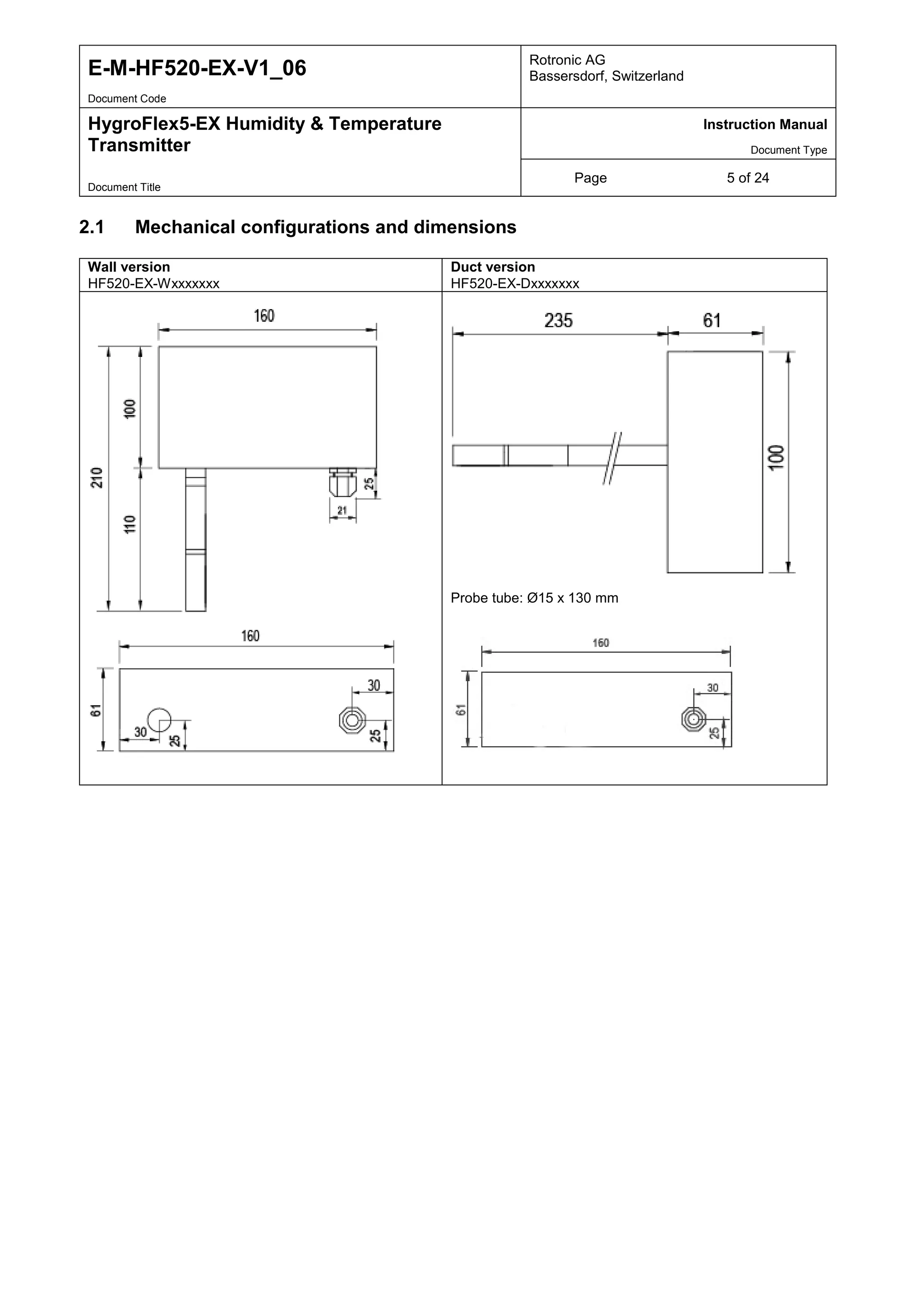
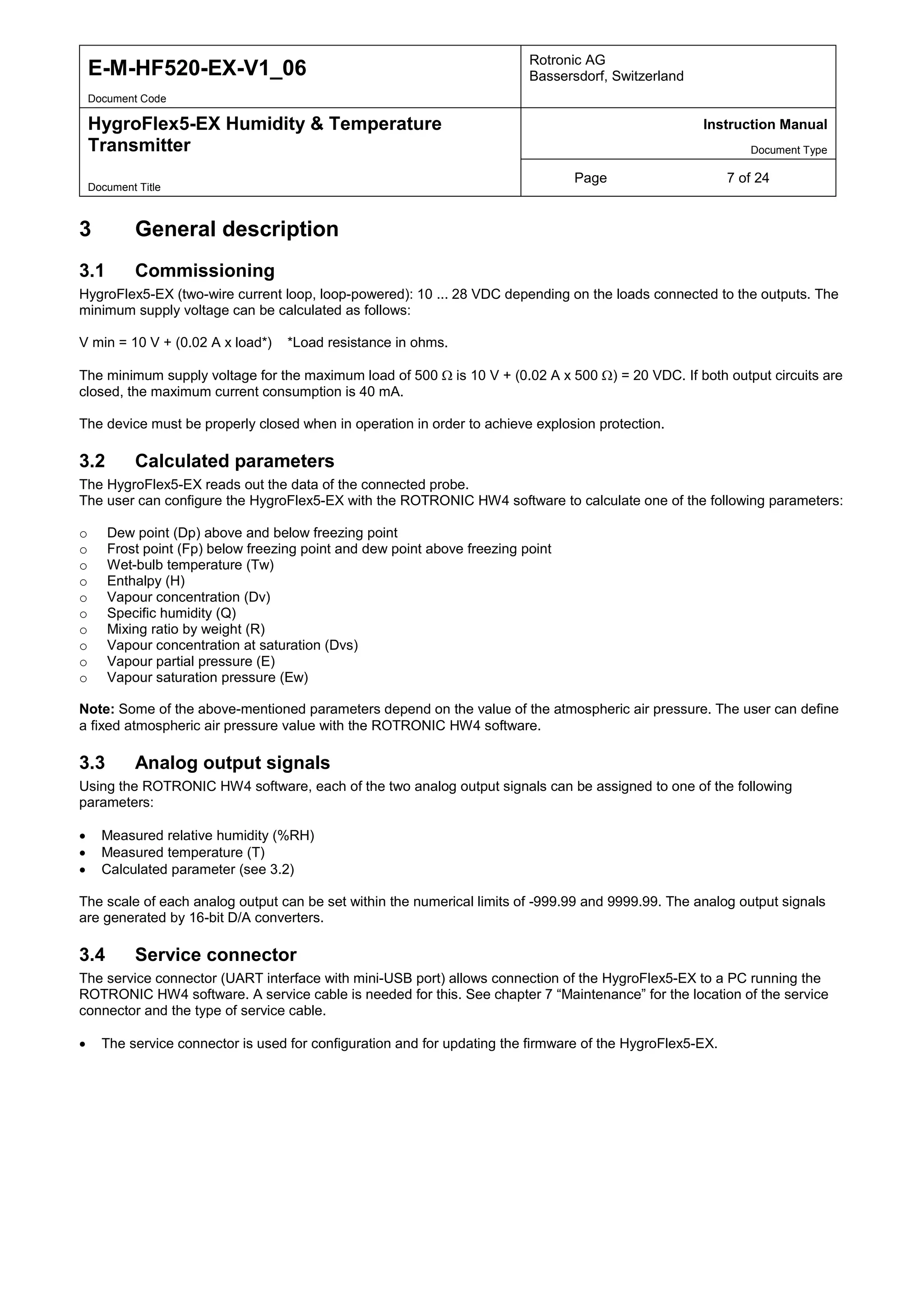
Wall version compatible with probes:
HC2-SM-EX
HC2-IM102-EX (Cable probe125 mm, cable length 2 m)
HC2-IM105-EX (Cable probe125 mm, cable length 5 m)
HC2-IM110-EX (Cable probe125 mm, cable length 10 m)
HC2-IM302-EX (Cable probe285 mm, cable length 2 m)
HC2-IM305-EX (Cable probe285 mm, cable length 5 m)
HC2-IM310-EX (Cable probe285 mm, cable length 10 m)
HC2-IE102-EX (Screw-in probe 1/2'' G thread, cable length 2 m)
HC2-IE105-EX (Screw-in probe 1/2'' G thread, cable length 5 m)
HC2-IE110-EX (Screw-in probe 1/2'' G thread, cable length 10 m)
HC2-IE302-EX (Screw-in probe 1/2'' NPT thread, cable length 2 m)
HC2-IE305-EX (Screw-in probe with 1/2'' G thread, cable length 5 m)
HC2-IE310-EX (Screw-in probe with 1/2'' G thread, cable length 10 m)
Duct version compatible with
probes:
HC2-SM-EX
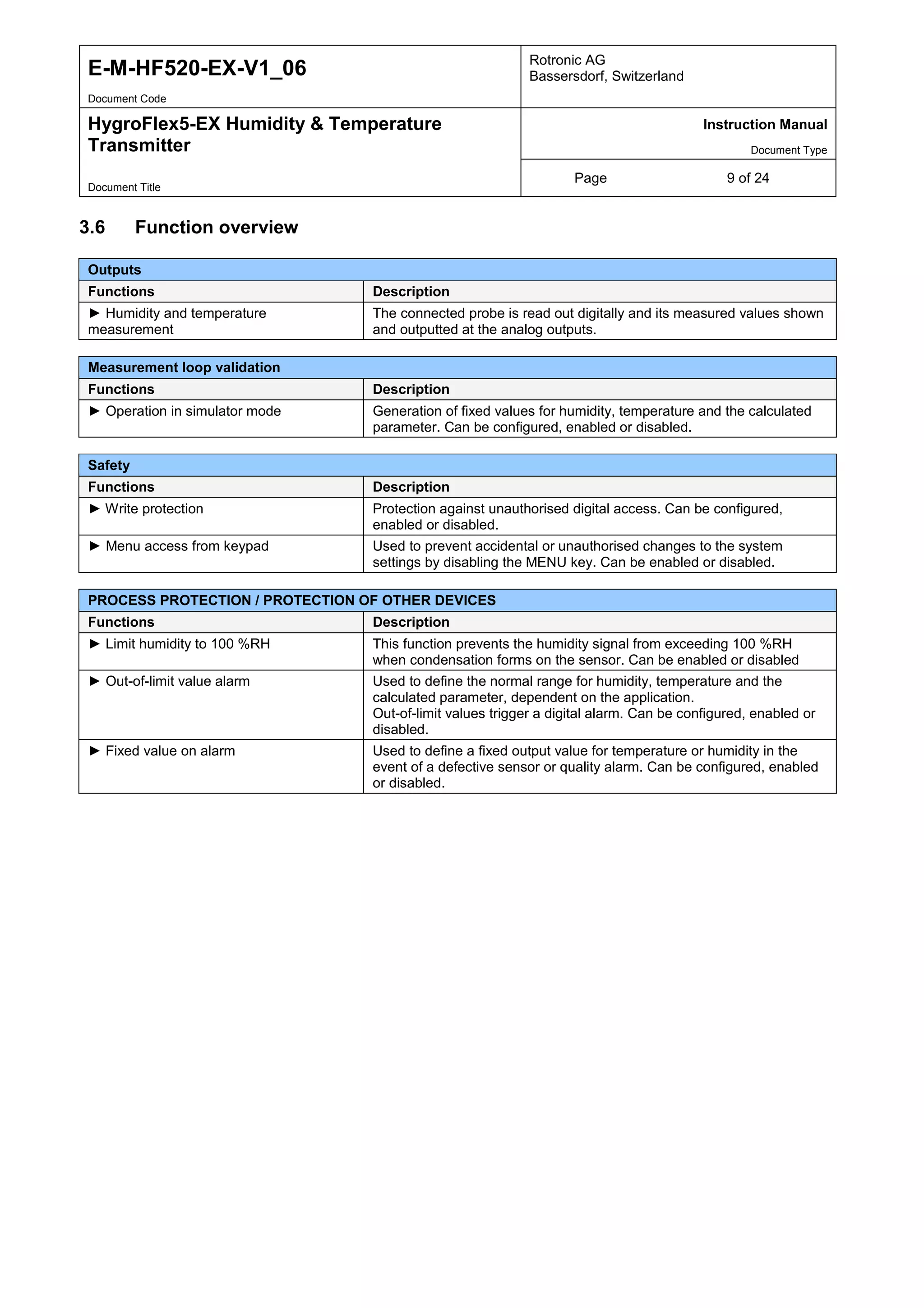
2.2 Display and keypad option
The optional LCD does not have a backlight.
The first line of the display shows the relative humidity (or a calculated value, e.g. dew point, frost point, ...) and the second
line the temperature (or a calculated value, e.g. dew point, frost point, ...).
The display can be configured to show a trend indicator at the start of every line:
▲: Increasing value
▼: Decreasing value
In the event of an alarm the display shows the symbol [ ! ] to the right of the value.](https://image.slidesharecdn.com/rotronichygroflex5-ex-hf5-exhazardousareahumiditytemperaturesensors-manual-141104035034-conversion-gate01/75/Rotronic-HygroFlex5-EX-HF5-EX-Hazardous-Area-Humidity-Temperature-Sensors-Manual-6-2048.jpg)
![E-M-HF520-EX-V1_06 Rotronic AG
Bassersdorf, Switzerland
Document Code
HygroFlex5-EX Humidity & Temperature
Transmitter
Instruction Manual
Document Type
Page 20 of 24
Document Title
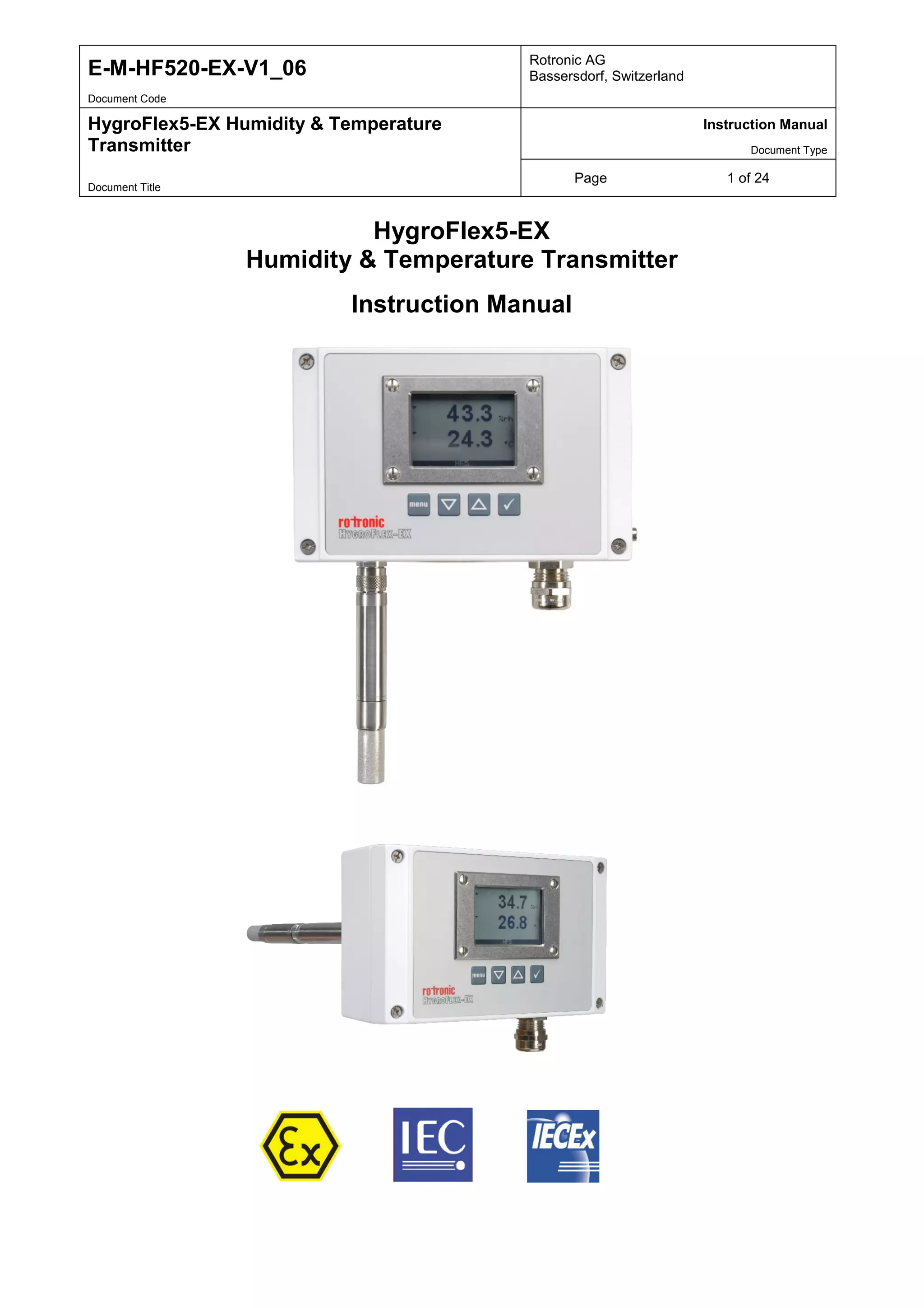
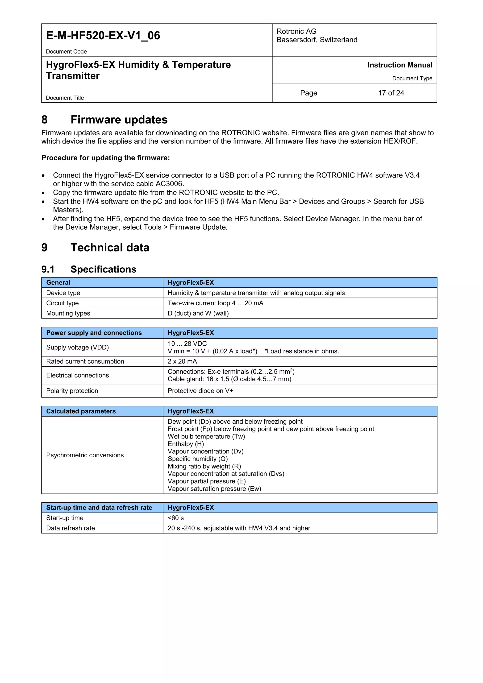
11 ATEX data
11.1 Ignition protection category, type
Measurement probe with HygroClip: For Zone 0/20
Transmitter: Complete transmitter for Zone 1/2 and 21/22
The following ATEX approval according to IEC is aimed at:
Device group II for explosive atmospheres (not mining)
Probe: II 1/2 G Ex ia IIC T5 Ga/Gb Zone 0, gas, intrinsically safe, temp. 100 °C
II 1/2 D Ex ia IIIC T80°C Da/Db Zone 20, dust, intrinsically safe, temp. 80 °C
IP66 IP protection 66
(1/2 - 1: Zone 0 and 2: Zone 1 suitable for mounting in zone separation wall)
(Ga - very high protection level (Zone 0), Gb - high protection level (Zone 1))
(Da - very high protection level (Zone 0), Db - high protection level (Zone 1))
(Ga/Gb, Da/Db suitable for mounting in zone separation wall)
Transmitter: II 2(1) G Ex eb mb [ia Ga] IIC T5 Gb Zone 1, 2, gas, (intrinsically safe), temp. 100 °C
II 2(1) D Ex tb [ia Ga] IIIC T80°C Db Zone 21, 22, dust, (intrinsically safe), temp. 80
°C
IP66 IP protection 66
(2(1) - 2: Zone 1, (1): contains electric circuits that may exist in Zone 0)
(Ex e mb [ia Ga] multiple ignition protection categories: Ex-e, Ex-mb and output Ex-ia)
Complete system: II 1/2 G Ex eb ia mb IIC T5 Ga/Gb
II 1/2 D Ex ia tb IIIC T80°C Da/Db
11.2 ATEX-relevant standards
The following European standards are relevant for the product:
CENELEC - European Committee for Electrotechnical Standardisation
EN 60 079 – 0 Part 0: Equipment – General requirements
Construction, testing, marking
EN 60079 – 7 Part 7: Equipment protection by increased safety “e”
EN 60 079 – 11 Part 11: Equipment protection by intrinsic safety “i”
EN 60 079 – 14 Part 14: Electrical installations design, selection and erection
EN 60 079 – 18 Part 18: Equipment protection by encapsulation “m”
EN 60 079 – 26 Part 26: Equipment with equipment protection level (EPL) Ga
Zone 0 requirements (EPL - Equipment protection level)
EN60079 – 31 Part 31: Equipment dust ignition protection by enclosure “t”](https://image.slidesharecdn.com/rotronichygroflex5-ex-hf5-exhazardousareahumiditytemperaturesensors-manual-141104035034-conversion-gate01/75/Rotronic-HygroFlex5-EX-HF5-EX-Hazardous-Area-Humidity-Temperature-Sensors-Manual-20-2048.jpg)
![E-M-HF520-EX-V1_06 Rotronic AG
Bassersdorf, Switzerland
Document Code
HygroFlex5-EX Humidity & Temperature
Transmitter
Instruction Manual
Document Type
Page 21 of 24
Document Title
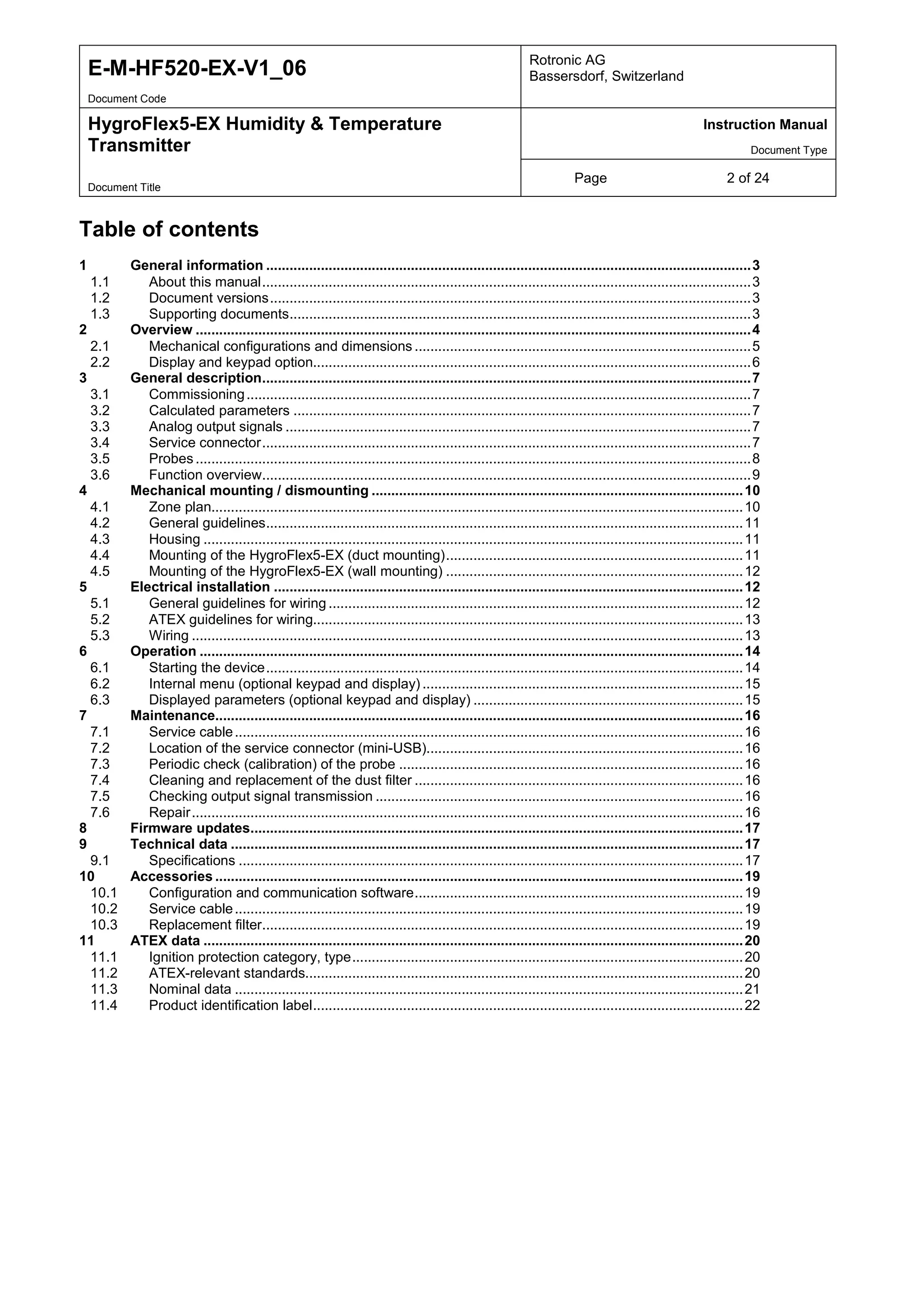
11.3 Nominal data
Power supply:
There are two separate connections available for the humidity and temperature sensors. The device connections
comprise power supply and sensor signal. The supply voltages for the two sensors may be different because
they are isolated by two internal diodes. The device can also be operated with only one loop.
Device input voltage: USupply = 20 V … 28 VDC [24 V +/- 15%]
Maximum current ISupply max. = 50 mA [Sum of both input currents]
Load impedance: RM = 100 … 500 Ω [Measurement voltages 2 V…10 V]
Ambient temperature range:
• Measurement probe: TA = [- 40 °C ... + 60 °C]
• Transmitter with LCD: TA = [- 10 °C … + 60 °C]
• Transmitter without LCD: TA = [- 40 °C … + 60 °C]
The normal ATEX standards only apply for normal temperatures [-20 °C … +40 °C] and for a pressure range of
[0.8 bar…1.1 bar]. The extended temperature range must be marked on the product identification label.
Input protection circuit:
The device is protected against polarity reversal by two diodes. In addition to this, two Z-Transil diodes protect
against static and transient overvoltages. These measures are not required by ATEX. They were, however,
implemented as easily realisable additional protective measures.](https://image.slidesharecdn.com/rotronichygroflex5-ex-hf5-exhazardousareahumiditytemperaturesensors-manual-141104035034-conversion-gate01/75/Rotronic-HygroFlex5-EX-HF5-EX-Hazardous-Area-Humidity-Temperature-Sensors-Manual-21-2048.jpg)
![E-M-HF520-EX-V1_06 Rotronic AG
Bassersdorf, Switzerland
Document Code
HygroFlex5-EX Humidity & Temperature
Transmitter
Instruction Manual
Document Type
Page 22 of 24
Document Title
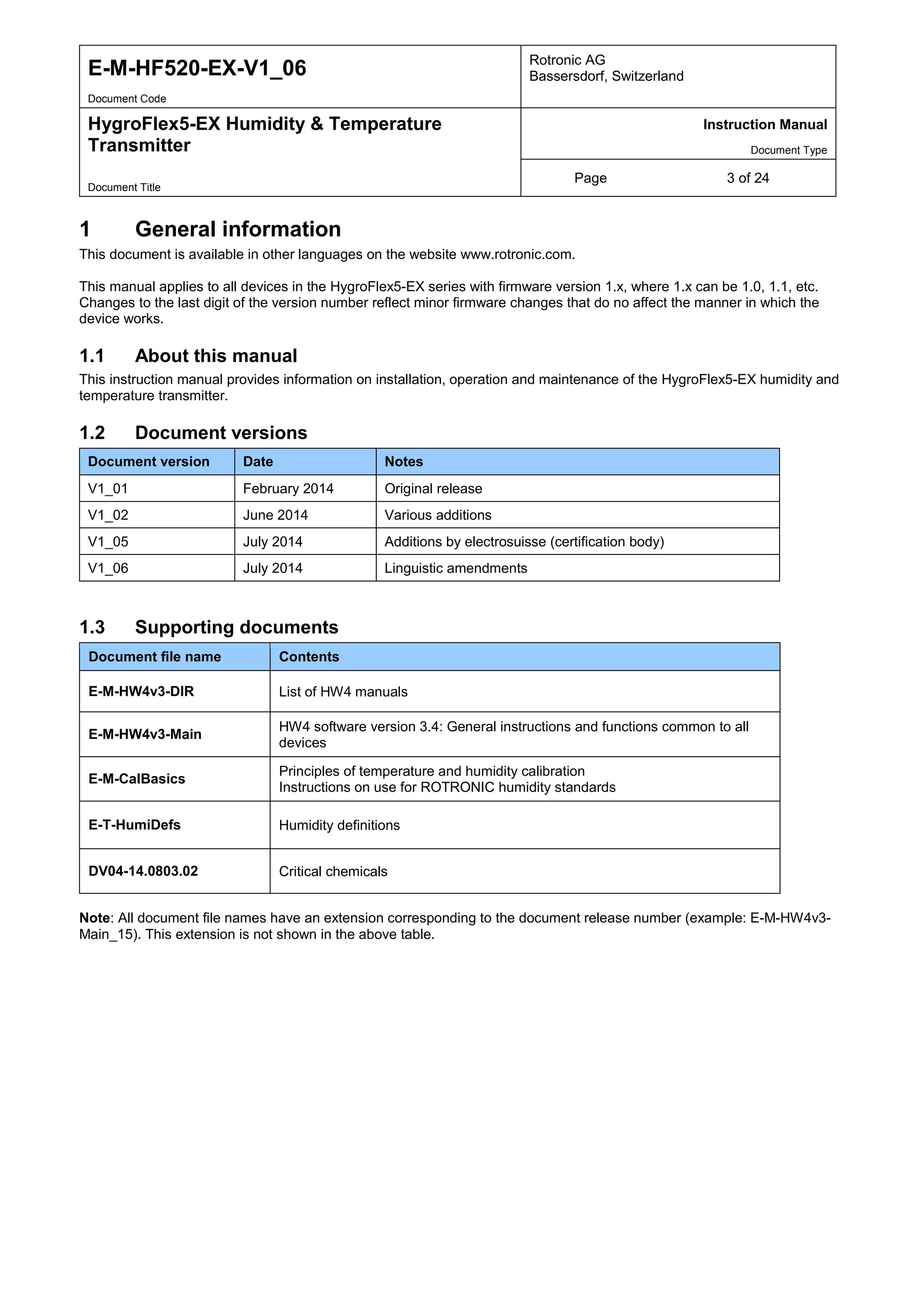
11.4 Product identification label
Manufacturer: Rotronic AG, CH-8303 Bassersdorf
Type designation: HF520-EX
Serial number: < Number >
Measurement probe: II 1/2 G Ex ia IIC T5 Ga/Gb
II 1/2 D Ex ia IIIC T80°C Da/Db
IP66
Transmitter: II 2(1) G Ex eb mb [ia Ga] IIC T5 Gb
II 2(1) D Ex tb [ia Ga] IIIC T80°C Db
IP66
Certification body and certificate no.: Electrosuisse, Fehraltdorf (CH)
SEV 14 ATEX 0107
IECEx SEV 14.0002
Date: 02.07.2014
Operating temperature range: Tamb = [-10 °C … +60 °C] with LCD
Tamb = [-40 °C … +60 °C] without LCD
In: [20 VDC … 28 VDC], 2 W
Out: [4 mA … 20 mA], 2-wire current loop
Symbols:](https://image.slidesharecdn.com/rotronichygroflex5-ex-hf5-exhazardousareahumiditytemperaturesensors-manual-141104035034-conversion-gate01/75/Rotronic-HygroFlex5-EX-HF5-EX-Hazardous-Area-Humidity-Temperature-Sensors-Manual-22-2048.jpg)


This document is the instruction manual for the HygroFlex5-EX humidity and temperature transmitter. It provides general information about the transmitter, an overview of its features and components, and instructions for mechanical installation, electrical installation, operation, maintenance, and firmware updates. The transmitter is designed for fixed installation in applications requiring high measurement accuracy and can measure humidity from 0-100% RH and temperature from -100 to 200°C. It has two analog outputs and a digital service interface.