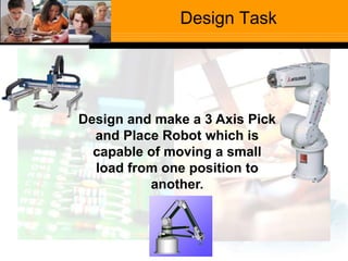
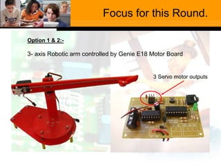
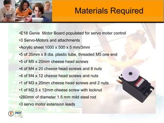
L.C. Technology
Professional Development for
Teachers
Feedback
Very positive response to Line following
Robot.
Genie E18 motor board used to control
robot, 2 LDR’s were used to provide
feedback to control position of robot
J’Cert Technology
Projects
Junior Certificate
Projects covered
Mobile Phone Holder
Desk Tidy
DVD Rack
Mood Light
Desktop Light
Photo Display
Bird House
Leaving Certificate
Technology
Sample Robotics Project
Design Task
Design and make a 3 Axis Pick
and Place Robot which is
capable of moving a small
load from one position to
another.
Syllabus Topics Addressed
Suggested Methodology
There are a number of approaches to this project.
Option 1:
Basic control of servo motors using control software to programme a
3 axis robot arm. The arm is to move to various locations and
provide pick and place capabilities.
Option 2:
Design a separate control panel to provide:
(i) control of two axis using 2 potentiometers.
(ii) a means of operating a gripper using an LDR
Option 3:
Challenge students to design a robotic system which will separate
different coloured balls / blocks into various containers.
Focus for this Round.
Option 1 & 2:-
3- axis Robotic arm controlled by Genie E18 Motor Board
3 Servo motor outputs
Materials Required
•E18 Genie Motor Board populated for servo motor control
•3 Servo-Motors and attachments
•Acrylic sheet 1000 x 500 x 5 mm/3mm
•5 of 35mm x 8 dia. plastic tube, threaded M5 one end
•5 of M5 x 20mm cheese head screws
•4 of M4 x 20 cheese head screws and 8 nuts
•4 of M4 x 12 cheese head screws and nuts
•1 of M3 x 20mm cheese head screws and 2 nuts
•1 of M2.5 x 12mm cheese screw with locknut
•280mm of diameter 1.5 mm mild steel rod
•3 servo motor extension leads
Health & Safety
The technology room Health and safety rules and regulations
apply.
Hazards specific to this project include the following:
Drilling acrylic and the risk of cracking.
Potential bonding of body tissue due to the use of
adhesives. The attention of students should be drawn
to this hazard and proper precautions should be
taken to minimise this risk.
Possible cutting from metal swarf on the end of mild
steel rod. Students attention should be drawn to this
hazard and the mitigation of the risk by removing the
swarf with a file after cutting.
End Effectors for Robot
Mechanical
Grippers
Magnetic Grippers
Vacuum Grippers
Electro-Magnetic
Gripper
Sample Calculation
If the weight of the servo motor equals 0.324N, calculate the mass of A,
which will allow the robotic arm rotate a mass of 180g to a new position
without the risk of toppling over.
A
24cm
105mm
Answer
Clockwise moment = Anti-clockwise moment
1.77N x .24 m = (0.324N x .07m) + (Force x .105m)
.42Nm = 0.022Nm + (Force x .105m)
.42Nm– 0.022Nm = .105m x Force
.398Nm = .105m x Force
.398/.105 = Force
3.79N = Force
Mass of A = 3.79 / 9.81
.386kg = 386 g
180Kg x 9.81 = 1.77N
24cm
105mm
A
Assessment
Students could be asked to carry out research on a theme based on
automation in the workspace / home / leisure / other?
Students could be asked to consider how the product could best be
manufactured and to compile a Gantt chart which displays the
manufacturing sequence for the project.
 The functionality, quality and finish of the product could
be assessed by the class teacher using assessment
guidelines given by State exams
 Artefact meets theme
 Originality and Creativity
 Production Skills
 Functionality
 Quality and Finish
 Presentation of Artefact
Assessment
THE END

Robotics Project 124456789 Overview.ppt

  • 1.
  • 2.
    Feedback Very positive responseto Line following Robot. Genie E18 motor board used to control robot, 2 LDR’s were used to provide feedback to control position of robot
  • 3.
    J’Cert Technology Projects Junior Certificate Projectscovered Mobile Phone Holder Desk Tidy DVD Rack Mood Light Desktop Light Photo Display Bird House
  • 4.
  • 5.
    Design Task Design andmake a 3 Axis Pick and Place Robot which is capable of moving a small load from one position to another.
  • 6.
  • 7.
    Suggested Methodology There area number of approaches to this project. Option 1: Basic control of servo motors using control software to programme a 3 axis robot arm. The arm is to move to various locations and provide pick and place capabilities. Option 2: Design a separate control panel to provide: (i) control of two axis using 2 potentiometers. (ii) a means of operating a gripper using an LDR Option 3: Challenge students to design a robotic system which will separate different coloured balls / blocks into various containers.
  • 8.
    Focus for thisRound. Option 1 & 2:- 3- axis Robotic arm controlled by Genie E18 Motor Board 3 Servo motor outputs
  • 9.
    Materials Required •E18 GenieMotor Board populated for servo motor control •3 Servo-Motors and attachments •Acrylic sheet 1000 x 500 x 5 mm/3mm •5 of 35mm x 8 dia. plastic tube, threaded M5 one end •5 of M5 x 20mm cheese head screws •4 of M4 x 20 cheese head screws and 8 nuts •4 of M4 x 12 cheese head screws and nuts •1 of M3 x 20mm cheese head screws and 2 nuts •1 of M2.5 x 12mm cheese screw with locknut •280mm of diameter 1.5 mm mild steel rod •3 servo motor extension leads
  • 10.
    Health & Safety Thetechnology room Health and safety rules and regulations apply. Hazards specific to this project include the following: Drilling acrylic and the risk of cracking. Potential bonding of body tissue due to the use of adhesives. The attention of students should be drawn to this hazard and proper precautions should be taken to minimise this risk. Possible cutting from metal swarf on the end of mild steel rod. Students attention should be drawn to this hazard and the mitigation of the risk by removing the swarf with a file after cutting.
  • 11.
    End Effectors forRobot Mechanical Grippers Magnetic Grippers Vacuum Grippers Electro-Magnetic Gripper
  • 12.
    Sample Calculation If theweight of the servo motor equals 0.324N, calculate the mass of A, which will allow the robotic arm rotate a mass of 180g to a new position without the risk of toppling over. A 24cm 105mm
  • 13.
    Answer Clockwise moment =Anti-clockwise moment 1.77N x .24 m = (0.324N x .07m) + (Force x .105m) .42Nm = 0.022Nm + (Force x .105m) .42Nm– 0.022Nm = .105m x Force .398Nm = .105m x Force .398/.105 = Force 3.79N = Force Mass of A = 3.79 / 9.81 .386kg = 386 g 180Kg x 9.81 = 1.77N 24cm 105mm A
  • 14.
    Assessment Students could beasked to carry out research on a theme based on automation in the workspace / home / leisure / other? Students could be asked to consider how the product could best be manufactured and to compile a Gantt chart which displays the manufacturing sequence for the project.
  • 15.
     The functionality,quality and finish of the product could be assessed by the class teacher using assessment guidelines given by State exams  Artefact meets theme  Originality and Creativity  Production Skills  Functionality  Quality and Finish  Presentation of Artefact Assessment
  • 16.