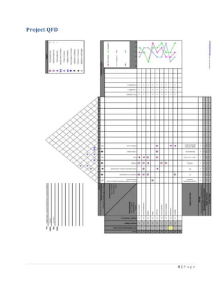
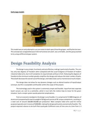
The document outlines the design process for a robotic arm capable of grabbing tires from multiple input locations, rotating them 180 degrees, and placing them on a single output location. Key aspects of the design include:
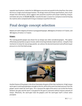
- A parallel 2-prong gripper to grab tires horizontally from 1 of 3 input locations.
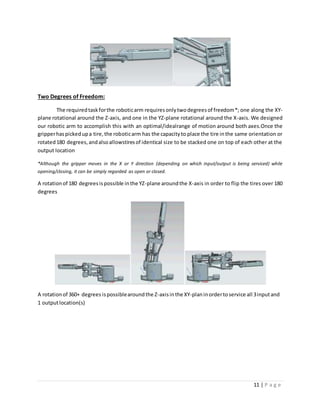
- Two degrees of freedom provided by rotation around the Z and X axes, allowing for tire flipping and placement.
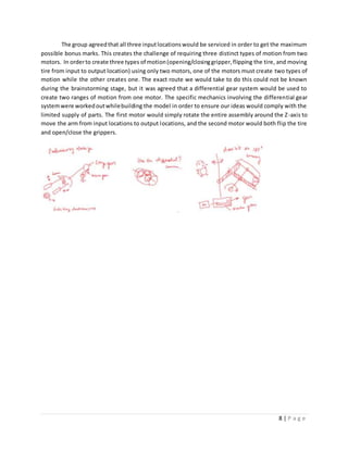
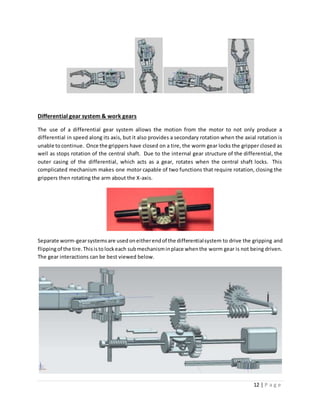
- A differential gear system powered by one motor to control both gripper movement and arm rotation.
- Worm gears to lock mechanisms in place when not in use for strength and reliability.
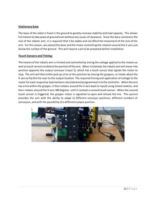
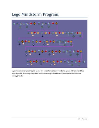
- Touch sensors and timed motor control to automate the process between input and output locations.