Roadside Design Guide 2006 With Updated Chapter 6 3rd Edition Anita Vandervalkostrander
Roadside Design Guide 2006 With Updated Chapter 6 3rd Edition Anita Vandervalkostrander
Roadside Design Guide 2006 With Updated Chapter 6 3rd Edition Anita Vandervalkostrander


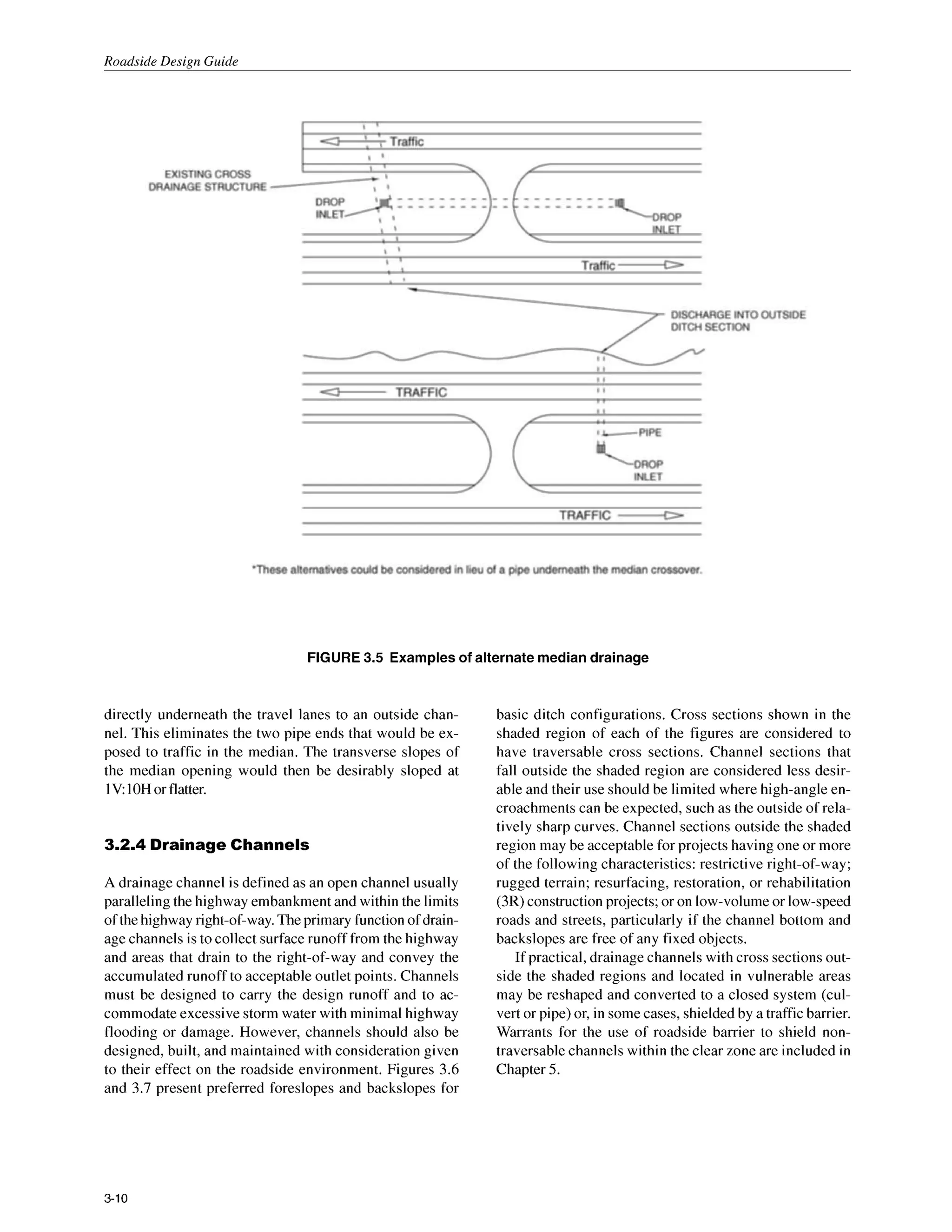
![Roadside Design Guide
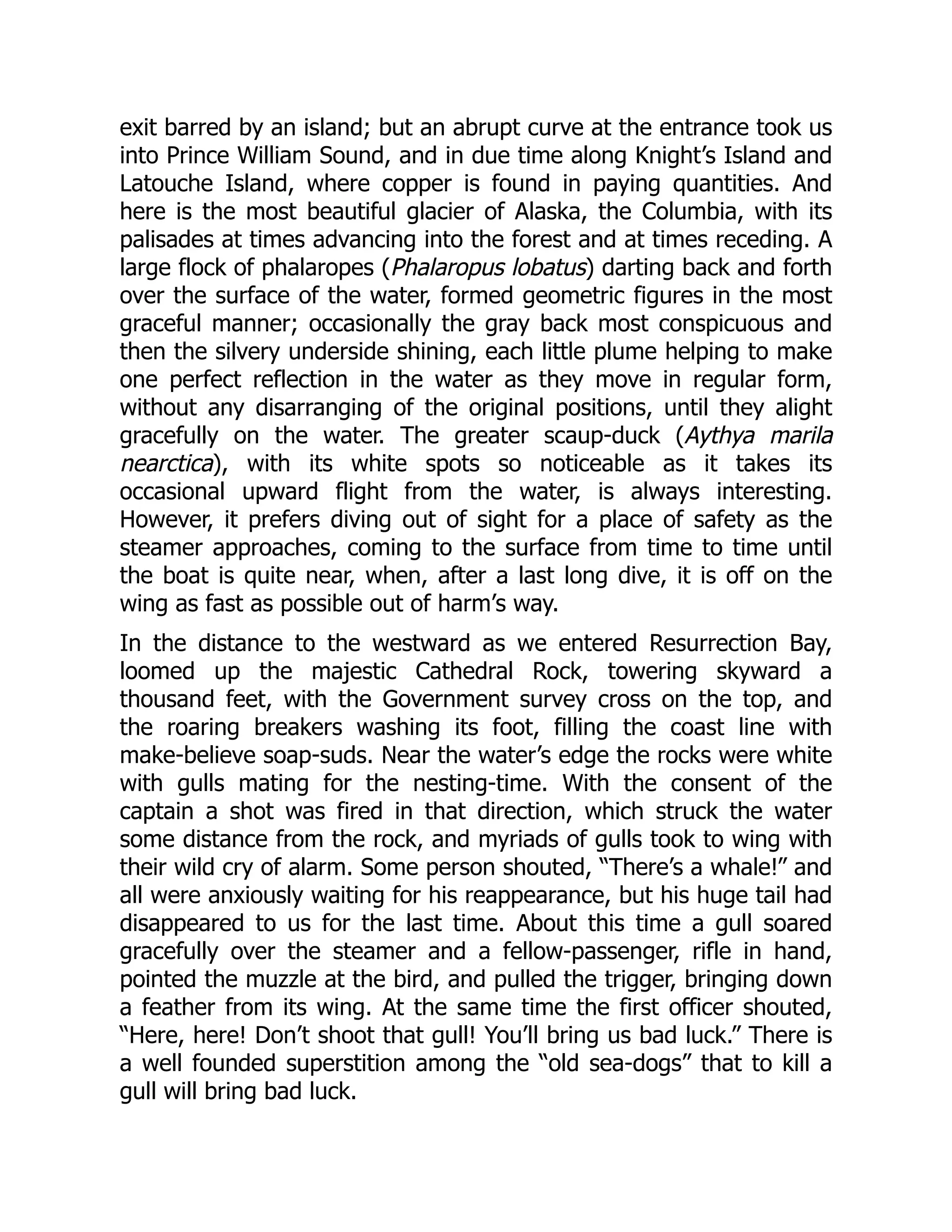
Glare Screen-A deviceused to shield a driver’seye from
the headlights of an oncoming vehicle.
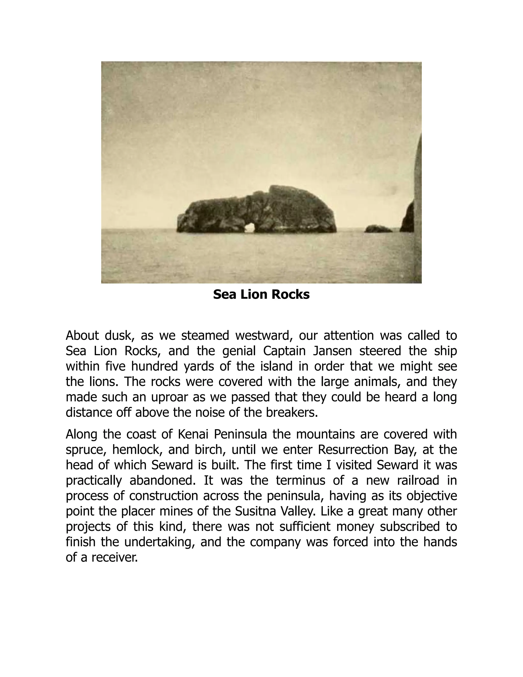
Hinge-The weakened section of a sign post designed to
allow the post to rotate upward when impacted by a ve-
hicle.
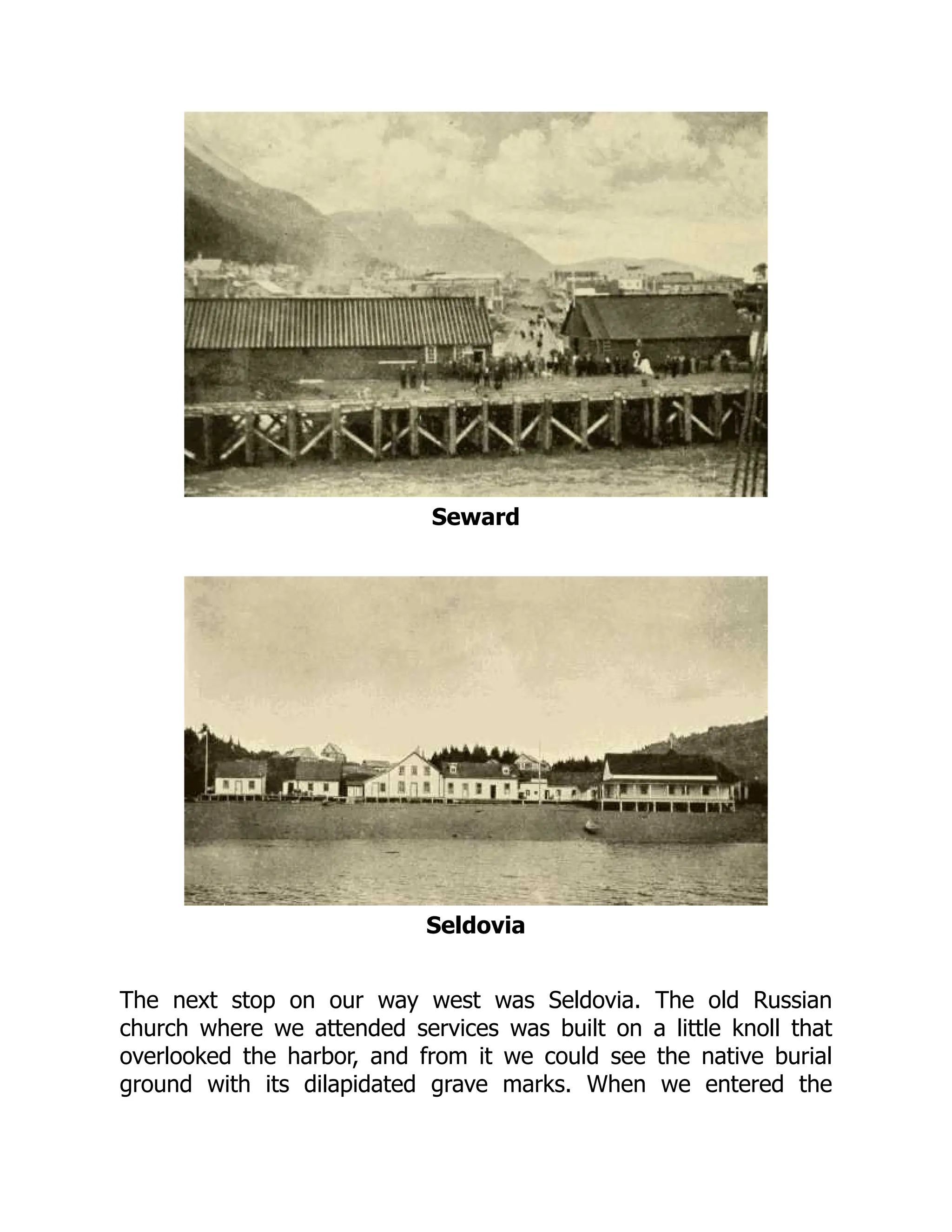
Impact Angle-For a longitudinal barrier, it is the angle
between a tangent to the face of the barrier and a tangent
to the vehicle’spath at impact.For a crashcushion, it is the
angle between the axis of symmetry of the crash cushion
and a tangent to the vehicle’s path at impact.
Impact Attenuator-See CrashCushion.
Length of Need-Total length of a longitudinal barrier
needed to shield an area of concern.
Level of Performance-The degree to which a longitudi-
nal barrier, including bridge railing, is designed for con-
tainment and redirection of different types of vehicles.
Longitudinal Barrier-A barrier whoseprimary function
is to prevent penetration and to safely redirect an errant
vehicle away from a roadside or median obstacle.
Median-The portion of a dividedhighway separating the
traveled ways for traffic in opposite directions.
Median Barrier-A longitudinal barrier used to prevent
an errant vehicle from crossing the highway median.
Non-Recoverable Slope-A slopewhich isconsideredtra-
versable but on which the errant vehicle will continue on
to the bottom. Embankment slopes between IV:3H and
IV4H may be consideredtraversablebut non-recoverable
if they are smooth and free of fixed objects.
Offset-Lateral distance from edge of traveled way to a
roadside object or feature.
Operating Speed-The highest speed at which reason-
ably prudent drivers can be expected to operate vehicles
on a section of highway under low traffic densities and
good weather. This speed may be higher or lower than
posted or legislated speed limits or nominal design speeds
where alignment, surface, roadside development, or other
features affect vehicle operations.
OperationalBarrier-One that has performed satisfacto-
rily in full-scale crash tests and has demonstrated satisfac-
tory in-serviceperformance.
Performance Level-See Levelof Performance.
Recoverable Slope-A slopeon which a motoristmay, to a
greateror lesserextent,retain orregaincontrolof a vehicle.
Slopesflatterthan lV:4H aregenerallyconsideredrecover-
able.
Recovery Area-Generally synonymouswith clear zone.
Roadside-That area between the outside shoulder edge
and theright-of-waylimits.The areabetween roadwaysof
a divided highway may also be considered roadside.
Roadside Barrier-A longitudinal barrier used to shield
roadside obstacles or non-traversable terrain features. It
may occasionally be used to protect pedestrians or “by-
standers”from vehicletraffic.
Roadside Signs-Roadside signscan be divided intothree
main categories: overhead signs,large roadside signs, and
small roadside signs.Large roadside signs may be defined
as thosegreaterthan or equal to 5m2 [50ft’] in area. Small
roadside signs may be defined as those less than
5m2[50ft’] in area.
Roadway-The portion of a highway, includingshoulders,
for vehicular use.
Rounding-The introduction of a vertical curve between
two transverse slopes to minimizethe abrupt slopechange
and to maximize vehicle stability and maneuverability.
Severity Index-A severity index (SI) is a number from
zero to ten used to categorize accidents by the probability
of their resulting in property damage, personal injury, or a
fatality, or any combination of these possible outcomes.
The resultant number can then be translated into an acci-
dent cost and the relative effectiveness of alternate safety
treatments can be estimated.
Shielding-The introduction of a barrier or crash cushion
between the vehicle and an obstacle or area of concern to
reduce the severity of impacts of errant vehicles.
Shy Distance-The distance from the edge of the traveled
way beyond which a roadside object will not be perceived
as an obstacle by the typical driver to the extent that the
driver will change the vehicle’s placement or speed.
Slip Base-A structuralelement at or near the bottom of a
post or pole which will allow release of the post from its
base upon impact while resisting wind loads.
Slope-The relative steepness of the terrain expressed as
a ratio or percentage. Slopes may be categorized as posi-
tive (backslopes) or negative (foreslopes) and as parallel
or cross slopes in relation to the direction of traffic.
G-2](https://image.slidesharecdn.com/2347692-250526105611-6c3d9c6b/75/Roadside-Design-Guide-2006-With-Updated-Chapter-6-3rd-Edition-Anita-Vandervalkostrander-9-2048.jpg)
![Glossarv
Temporary Barrier-Temporary barriersare used to pre-
vent vehicular access into construction or maintenance
work zones and to redirect an impacting vehicle so as to
minimize damage to the vehicle and injury to the occu-
pants while providing worker protection.
Traffic Barrier-A deviceused to prevent a vehiclefrom
striking a more severe obstacle or feature located on the
roadside or in the median or to prevent crossover median
accidents. As defined herein, there are four classes of traf-
ficbarriers,namely,roadsidebarriers,median barriers,bridge
railings, and crash cushions.
Transition-A section of barrier between two different
barriersor,morecommonly,wherea roadsidebarrier iscon-
nected to a bridge railing or to a rigid object such as a
bridge pier. The transition should produce a gradual stiff-
ening of the approach rail so vehicular pocketing, snag-
ging, or penetration at the connection can be avoided.
Traveled Way-The portion of the roadway for the move-
ment of vehicles, exclusive of shoulders.
Through Traveled Way-The portion of roadway for the
movementof vehicles,exclusiveof shouldersand auxiliary
lanes.
Traversable Slope-A slopefromwhich a motoristwill be
unlikely to steer back to the roadway but may be able to
slow and stop safely. Slopes between lV:3H and 1V:4H
generally fall into this category.
Vehicle-A motorized unit for use in transportingpassen-
gers or freight,ranging from an 820-kg [1,800-lb]automo-
bile to a 36000-kg [80,000-lb]van-typetractor-trailer.
Warrants-The criteria by which the need for a safety
treatmentor improvementcan be determined.
G 3](https://image.slidesharecdn.com/2347692-250526105611-6c3d9c6b/75/Roadside-Design-Guide-2006-With-Updated-Chapter-6-3rd-Edition-Anita-Vandervalkostrander-10-2048.jpg)
![Chapter I
An Introduction to Roadside Safety
1.0 HISTORY OF ROADSIDESAFETY
Roadside safety design, as one component of total high-
way design, is a relatively recent concept. Most of the
highway design components were established in the late
1940s and the 1950s. These components included hori-
zontal alignment, vertical alignment, hydraulic design, and
sight distance to name some of the most common high-
way design elements. These elements have been revised
and refined over the years through experience and re-
search. However, the highway design components them-
selves have remained about the same for several decades.
Roadside safety design did not become a much dis-
cussed aspect of highway design until the late 1960s,and
it was the decade of the 1970s before this type of design
was regularly incorporated into highway projects. Because
most highways are designed for twenty- to thirty-year
projected traffic volumes, many roadway projects placed
in servicebefore the 1970s are only now becoming candi-
dates for major reconstruction.This reconstruction offers
an opportunity to incorporate cost-effective roadside
safety concepts and design features. The purpose of this
Guide is to present the concepts of roadside safety to the
designer in such a way that the most practical, appropri-
ate, and beneficial roadside design can be accomplished
for each project.
1.1THE BENEFITS OF ROADSIDESAFETY
Roadside design might be defined as the design of the
area between the outside shoulder edge and the
right-of-way limits. Some have referred to this aspect of
highway design as off-pavementdesign. A question com-
monly asked revolves around whether spending resources
off the pavement is really beneficial given the limited na-
ture of infrastructure funds. Perhaps, some statistics bring
the potential of crash reduction and roadside safety into
focus.
The United States suffers approximately 40,000traffic
fatalities each year. The actual number has fluctuated
around this level since the mid- 1960s. At the same time,
the number of vehicle kilometers [miles] traveled each year
has increased approximately two and one-half times since
the mid- 1960s. Therefore, the traffic fatality rate per one
billion vehicle kilometers [miles] given in Figure 1.1has
fallen by more than half since the mid-1960s.
This significant reduction is due to several factors.
Motor vehicles are much safer than they were in the past.
Protected passenger compartments, padded interiors, and
occupant restraints are some features that have added to
passenger safety during impact situations. Roadways
have been made safer through design improvements such
as increased superelevation, intersection geometry, and
the addition of grade separations. Drivers are more edu-
cated about safe vehicle operation as evidenced by the
increased use of occupant restraints and a decrease in
driving under the influence of alcohol or drugs. All these
contributing factors have reduced the motor vehicle fatal-
ity rate.
How significant is the involvement of the roadside en-
vironment in highway crashes? Unfortunately, roadside
crashes account for far too great a portion of the total fatal
highway crashes. About thirty percent, or almost one in
every three fatalities, are the result of a single vehicle
run-off-the-road crash. These figures mean that the road-
side environment comes into play in a very significant
percentage of fatal and serious-injury crashes.
1-1](https://image.slidesharecdn.com/2347692-250526105611-6c3d9c6b/75/Roadside-Design-Guide-2006-With-Updated-Chapter-6-3rd-Edition-Anita-Vandervalkostrander-19-2048.jpg)
![Roadside Design Guide
FIGURE 1.1 Traffic fatality rate per billion vehicle kilometers [miles] by year
1.2 THE FORGIVING ROADSIDECONCEPT
There are many reasons why a vehicle will leave the pave-
ment and encroach on the roadside, including:
driver fatigue or inattention
excessive speed
driving under the influence of drugs or alcohol
crash avoidance
roadway conditions such as ice, snow, or rain
vehicle component failure
poor visibility
Regardless of the reason for a vehicleleaving the road-
way, a roadside environment free of fixed objects with
stable, flattened slopes enhances the opportunity for re-
ducing crash severity. The forgiving roadside concept al-
lows for errant vehicles leaving the roadway and sup-
ports a roadside design where the serious consequences
of such an incident are reduced.
Through decades of experience and research, the ap-
plication of the forgiving roadside concept has been re-
fined to the point where roadside design is an integral part
of transportation design criteria. Design options for re-
ducing roadside obstacles, in order of preference, are as
follows:
I. Remove the obstacle.
2. Redesign the obstacle so it can be safely tra-
versed.
3. Relocate the obstacle to a point where it is less
likely to be struck.
4. Reduce impact severity by using an appropriate
breakaway device.
5. Shieldthe obstaclewith a longitudinal traffic bar-
rier designed for redirection or use a crash cush-
ion.
6. Delineate the obstacle if the above alternatives
are not appropriate.
One on-roadway safety feature that is becoming more
prevalent nationwide on facilities experiencing a signifi-
cant number of run-off-the-roadcrashesis the use of trans-
verse milled shoulder rumble strips to supplement pave-
ment edge lines. These indentations in the roadway shoul-
ders alert motorists through noise and vibration that their
1-2](https://image.slidesharecdn.com/2347692-250526105611-6c3d9c6b/75/Roadside-Design-Guide-2006-With-Updated-Chapter-6-3rd-Edition-Anita-Vandervalkostrander-20-2048.jpg)
![Roadside Design Guide
NCHRP Report 350 presents specific impact conditions
for conducting vehicle crash tests. The conditions include
vehicle mass [weight], speed, approach angle, and point
on the safety feature to be hit. Standard test vehicle types
are defined for small passenger cars, standard %-ton pickup
trucks, single-unit van trucks, tractodvan-type trailer
units, and tractorhanker trailer units. The impact speeds
range from 35 to 100km/h [approximately 20 to 60 mph]
and approach angles vary from 0 to 25 degrees. The spe-
cific NCHRP Report 350 test conditions and evaluation
criteria for each type of roadside deviceare summarized in
the chapters that address that type of device. The report
itself is out-of-print but can be viewed and downloaded
from the following web site: http://
www4.nationalacademies.org/trb/crp.nsf/
NCHRP+projects. From this site, NCHRP Report 350can
be found by clicking on Area 22, then on Project 22-7. The
file is very large and is primarily intended for research
personnel who conduct the actual crash testing.
1.5 THE APPLICATION OF THIS GUIDE
This publication is intended to present information on the
latest state-of-the-practice in roadside safety. The con-
cepts, designs, and philosophies presented in the follow-
ing chapters can not, and should not, be included in their
totality on every single project. Each project is unique
and offers an individual opportunity to enhance that par-
ticular roadside environment from a safety perspective.
The guidelines presented in this publication are most
applicable to new construction or major reconstruction
projects. These projects, which often include significant
changes in horizontal or vertical alignment, offer the great-
est opportunity for implementing many of the roadside
safety enhancements presented in this document. For re-
surfacing, rehabilitation, or restoration (3R) projects, the
primary emphasis is generally placed on the roadway it-
self to maintain the structural integrity of the pavement. It
will generally be necessary to selectively incorporate road-
side safety guidelines on 3R projects only at locations
where the greatest safety benefit can be realized. Because
of the scope of 3R projects and the limited nature of most
rehabilitation programs, the identification of areas that
offer the greatest safety enhancement potential is critical.
Accident reports, site investigations, and maintenance
records offer starting points for identifying these loca-
tions.
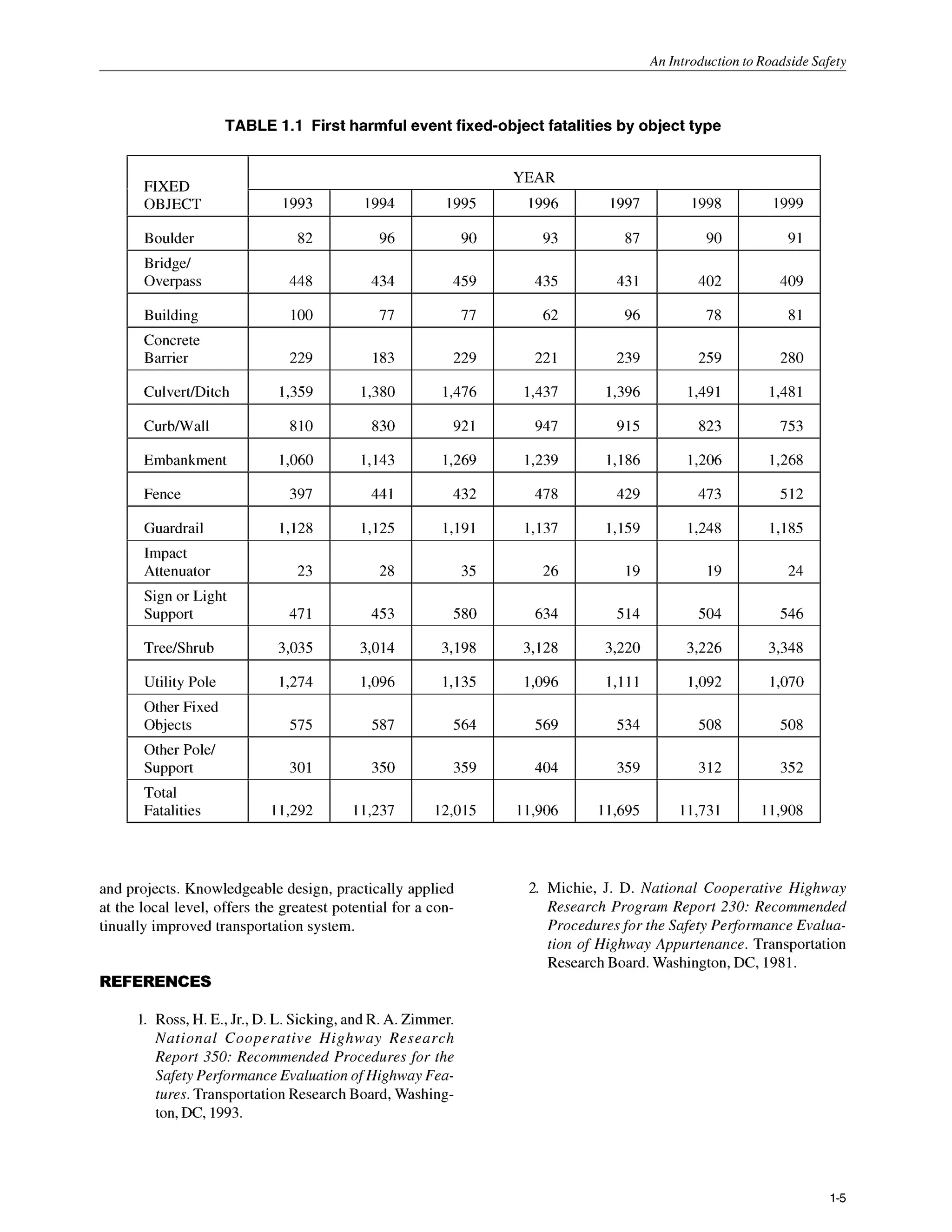
The importance of designing the roadside to be as clear
as practical can be seen by noting which objects and slope
conditions are most frequently associated with fatal run-
off-the-road crashes. Table I .I shows the numbers of fa-
talities in the United States from 1993 to I999 resulting
from collisions with specific roadside objects or slope
conditions. This information was obtained through the
National Highway Traffic Safety Administration’s
(NHTSA) Fatality Analysis Reporting System (FARS) and
identifies the first harmful event in a series of events re-
sulting in a fatal crash. In some cases, the first harmful
event is also identified as the most harmful event. For
example, if a motorist strikesa tree, the impact with the tree
is likely to be classified as both the first and most harmful
event. On the other hand, if the first harmful event is strik-
ing an embankment, the most harmful event is often a
rollover. FARS data for each State can be accessed di-
rectly at http://www-fars.nhtsa.dot.gov.
The amount of monetary resources available for all road-
side safety enhancements is limited. The objective of de-
signers has to be to maximize roadside safety on a
system-wide basis with the given funds. Accomplishing
this objective means addressing those specific roadside
features that can contribute the most to the safety en-
hancement of that individual highway project. If the inclu-
sion of the highest level of roadside design criteria is rou-
tinely required in each highway design project, regardless
of cost or safety effectiveness, it is likely that system-wide
safety may stay static or may be degraded. This potential
will certainly exist if other roadside needs are not improved
because funds were not judiciously applied to the most
viable safety enhancement need.
Given the fact that objects and slope changes must be
introduced at varying points off the pavement edge, the
enhancement of roadside safety involves selecting the
“best” choice among several acceptable design alterna-
tives. The experience gained from decades of selecting
design alternatives, the research done on vehicle dynam-
ics, and the technological advances in materials offers the
potential for maintaining and enhancing one of the safest
national transportation systems in existence.
This document is intended to represent the spectrum
of commonly available roadside design alternatives. In
most cases, these alternatives have shown significant
benefits under appropriately selected field conditions.
Many of these roadside enhancements have, over time,
demonstrated their ability in the field to improve roadside
safety conditions. In many areas, this publication strives
to give the advantages and disadvantages of roadside
technology. With this information, designers can make
more knowledgeable decisions about the best applications
for individual projects. It should be noted that no attempt
is made, or implied, to offer every single roadside enhance-
ment design technique or technology.
Finally, this publication is not intended to be used as a
standard or a policy statement. This document is made
available to be a resource for current information in the
area of roadside design. Agencies may choose to use this
information as one reference upon which to build the road-
side design criteria best suited to their particular location
1-4](https://image.slidesharecdn.com/2347692-250526105611-6c3d9c6b/75/Roadside-Design-Guide-2006-With-Updated-Chapter-6-3rd-Edition-Anita-Vandervalkostrander-22-2048.jpg)
![Roadside Design Guide
2.1.
IEncroachments 2.1.3 Crash Costs
The benefits derived from a roadside safety treatment can
be calculated by first estimating the number of vehicles
that are likely to run off the road at a particular location.
By definition, an encroachment occurs when a motorist
strays from the traveled way. The primary factors that af-
fect the number of encroachments are traffic volume, road-
way alignment, and lane widths. The number of estimated
encroachments is determined by multiplying an encroach-
ment rate by the number of vehicles using the facility,
resulting in a figurerepresenting the number of encroach-
ments per kilometer [mile] per year. Current encroachment
rates are derived from a limited number of studies con-
ducted over the past 30 years (1,2). These rates should be
adjusted when actual data at a specific location are avail-
able. They may also be modified based on engineering
judgment for non-typical conditions.
It should be further noted that not all encroachments
result in crashes. For example, for small-angle encroach-
ments, even a narrow recovery area may provide enough
space for a driver to regain control and return safely to the
roadway. To estimate the number of crashes that may re-
sult from encroachments,the angles of departurefrom the
roadway and the speeds and types of vehicles involved
must be considered.
Once an estimate has been made of the number of crashes
that can be expected at a given location, this information
must be translated into a cost that is directly related to
crash severity. One method of accomplishing this is by
assigning a Severity Index (SI)to individual crashes. This
SI will vary with the type of vehicle involved, its speed
and impact angle, and the type of obstacle struck.A crash
may range in severity from minor to fatal. If an SI system is
used, a crash involving no personal injuries and negli-
gible property damage might be assigned an SI of zero,
while a crash with a 100percent chance of a fatality might
be assigned an SI of 10. Between these extremes, crashes
typically involve varying degrees of property damage
coupled with slight, moderate, or severepersonal injuries.
Converting severity indices to crash cost is a relatively
easy process, but it does require that a dollar cost be
assigned to each type of crash. This step involves con-
siderable judgment because it requires that a value be
assigned to each crash classification, including fatal
crashes. Primary sources of crash cost data include the
National Safety Council, the National Highway Traffic
Safety Administration,and the Federal Highway Admin-
istration.
2.2 BENEFlTlCOSTANALYSIS PROGRAMS
2.1.2 Roadside Geometry
Once a vehicle has left the roadway, a crash may or may
not occur. The end result of an encroachment depends
upon the physical characteristicsof the roadside environ-
ment. As noted earlier, the highway designerhas a signifi-
cant degree of control over roadside geometry and appur-
tenances. Flat, traversable, stable slopes will minimize
overturning crashes, which are usually severe. Elimina-
tion of roadside hardware, its relocation to less vulnerable
areas, or the use of breakaway-type devices remain the
options of choice in the development of safer roadsides.
Obstructions that cannot otherwise be treated should be
shielded by properly designed and installed traffic barr-
ers or crash cushions if it is cost-effective to do so. Fi-
nally, if a fixed object or other roadside obstacle cannotbe
eliminated, relocated, modified, or shielded for whatever
reason, consideration should be given to delineating the
feature so it is readily visible to a motorist.
Several highway agencies have used the ROADSIDE
analysis program presented in the two earlier editions of
the Roadside Design Guide to both analyze site-specific
alternative safety treatments and to develop design charts
and tables using local data. Information on an updated
and significantly revised version of ROADSIDE, called
the Roadside Safety Analysis Program (RSAP), is included
in Appendix A.
REFERENCES
Hutchinson, J. W., and T. W. Kennedy. Medians
of Divided Highways-Frequency and Nature
of VehicleEncroachments. Bulletin 487. Univer-
sity of Illinois Engineering Experiment Station,
1966.
Cooper, P. “Analysis of Roadside Encroach-
ments-Single Vehicle Run-off-Road Accident
Data Analysis for Five Provinces,” B.C.Research.
Vancouver, British Columbia, Canada, March
1980.
2-2](https://image.slidesharecdn.com/2347692-250526105611-6c3d9c6b/75/Roadside-Design-Guide-2006-With-Updated-Chapter-6-3rd-Edition-Anita-Vandervalkostrander-25-2048.jpg)
![Roadside Topography and Drainage Features
3.0 OVERVIEW
This chapter includes a discussion on the development
and evaluation of the clear roadside concept and its appli-
cation to roadside design. It also discusses embankment
slopes and ditches and how these features influenceroad-
side features such as curbs, culverts, and drop inlets,
whose purpose is to provide adequate roadway drainage.
The designer is presented with several options that en-
hance safety without affecting the capabilities of these
elements to drain the highway.
Most of the clear roadside design guidelinesdiscussed
in this chapter have been practiced to varying degrees for
several years. This chapter attempts to reemphasize and
collect the currently accepted design principles to pro-
vide guidance in the area of roadside clearances. How-
ever, to include every recommendation or design value in
this chapter on every future highway project is neither
feasible nor possible. Engineeringjudgment will have to
play a part in determining the extent to which improve-
ments can reasonably be made with the limited resources
available.
As the designer studies the options available, some
consideration should be given to the future maintenance
of drainage facilities and roadside topography. Ongoing
repair and upkeep will be necessary to ensure the contin-
ued function and safety of various roadside drainage fea-
tures. Personnel, materials, equipment, and cost are some
of the considerations in every maintenance program. The
designer should take into account the exposure of crews
to traffic conditions while completing repairs. Also, main-
tenance activities can cause various levels of disruption
in the traffic flow, which may increase the potential for
crashes.
3.1 THE CLEAR ROADSIDECONCEPT
Beginning in the early 196Os,as more Interstate highways
and other freeways were opened to traffic, the nature and
characteristics of the typical rural highway crash began to
change. Instead of head-on crashes with other vehicles or
crashes involving trees immediately adjacent to the road-
way, many drivers were running off the new freewaysand
colliding with man-made objects such as bridge piers, sign
supports, culverts, ditches, and other design features of
the roadway. In 1967,the AASHO Traffic Safety Commit-
tee (currently the AASHTO Standing Committee on High-
way Traffic Safety) issued a report entitled Highway De-
sign and Operational Practices Related toHighway Safety
(1).This document became known as the “Yellow Book”
and its principles were widely applied to highway con-
struction projects, particularly high-speed controlled ac-
cess facilities. A second edition of the Yellow Book, pub-
lished by AASHTO in 1974, stated that “for adequate
safety, it is desirable to provide an unencumbered road-
siderecovery area that is as wide as practical on a specific
highway section. Studies have indicated that on high-
speed highways, a width of 9 meters [30feet] or more from
the edge of the through traveled way permits about 80
percent of the vehicles leaving a roadway out of control
to recover.”
Subsequently, most highway agencies began to try to
provide a traversable and unobstructed roadside area
(clear zone) extending approximately 9 m [30 ft] beyond
the edge of the through traveled way, particularly on high-
volume, high-speed roadways. Many obstacles located
within this clear-zone distance were removed, relocated,
redesigned, or shielded by traffic barriers or crash cush-
ions. It soon became apparent, however, that in some lim-
3-1](https://image.slidesharecdn.com/2347692-250526105611-6c3d9c6b/75/Roadside-Design-Guide-2006-With-Updated-Chapter-6-3rd-Edition-Anita-Vandervalkostrander-26-2048.jpg)
![Roadside Design Guide
ited situationswhere the embankmentsloped significantly
downward, a vehicle could encroach farther from the
through traveled way; thus, a 9 m [30 ft] recovery area
might not be adequate. Conversely, on most low-volume
or low-speed facilities, a 9 m [30 ft] clear-zone distance
was considered excessive and could seldom be justified
for engineering, environmental, or economic reasons.
The 1977AASHTO Guidefor Selecting, Locating and
Designing Traffic Barriers (2) modified the earlier clear-
zoneconcept by introducingvariable clear-zonedistances
based on traffic volumes, speeds and roadside geometry.
Figure 3.1 or Table 3.1 can be used to determine the sug-
gested clear-zone distance for selected traffic volumes
and speeds. However, Figure 3.1 and Table 3.1 only pro-
vide a generalapproximationof the needed clear-zonedis-
tance. The curves are based on limited empirical data that
was extrapolated to provide information for a wide range
of conditions. The designer must keep in mind site-spe-
cific conditions, design speeds, rural versus urban loca-
tions, and practicality. The distances obtained from Fig-
ure 3.1 and Table 3.1 should suggestonly the approximate
center of a range to be considered and not a precise dis-
tance to be held as absolute.
The designer may choose to modify the clear-zone dis-
tance for horizontalcurvature obtained from either Figure
3.1 or Table 3.1 by using Table 3.2. These modifications
are normally considered only when crash histories indi-
cate a need, or a specific site investigation shows a defini-
tive crash potential that could be significantly lessened
by increasing the clear-zone width, and when such in-
creases are cost effective. Horizontal curves, particularly
for high-speed facilities, are usually superelevated to in-
crease safety and provide a more comfortable ride. In-
creased banking on curves where the superelevation is
inadequate is an alternate method of increasing roadway
safety within a horizontal curve, except where snow and
ice conditions limit the use of increased superelevation.
For relatively flat and level roadsides, the clear-zone
concept is simple to apply. However, it is less clear when
the roadway is in a fill or cut section where roadsideslopes
may be either positive, negative, or variable, or where a
drainage channel exists near the through traveled way.
Consequently, these features must be discussed before a
full understanding of the clear-zone concept is possible.
The AASHTO publicationA Policy on Geometric Design
of Highways and Streets (3) may be referenced for addi-
tional clear-zone discussion.
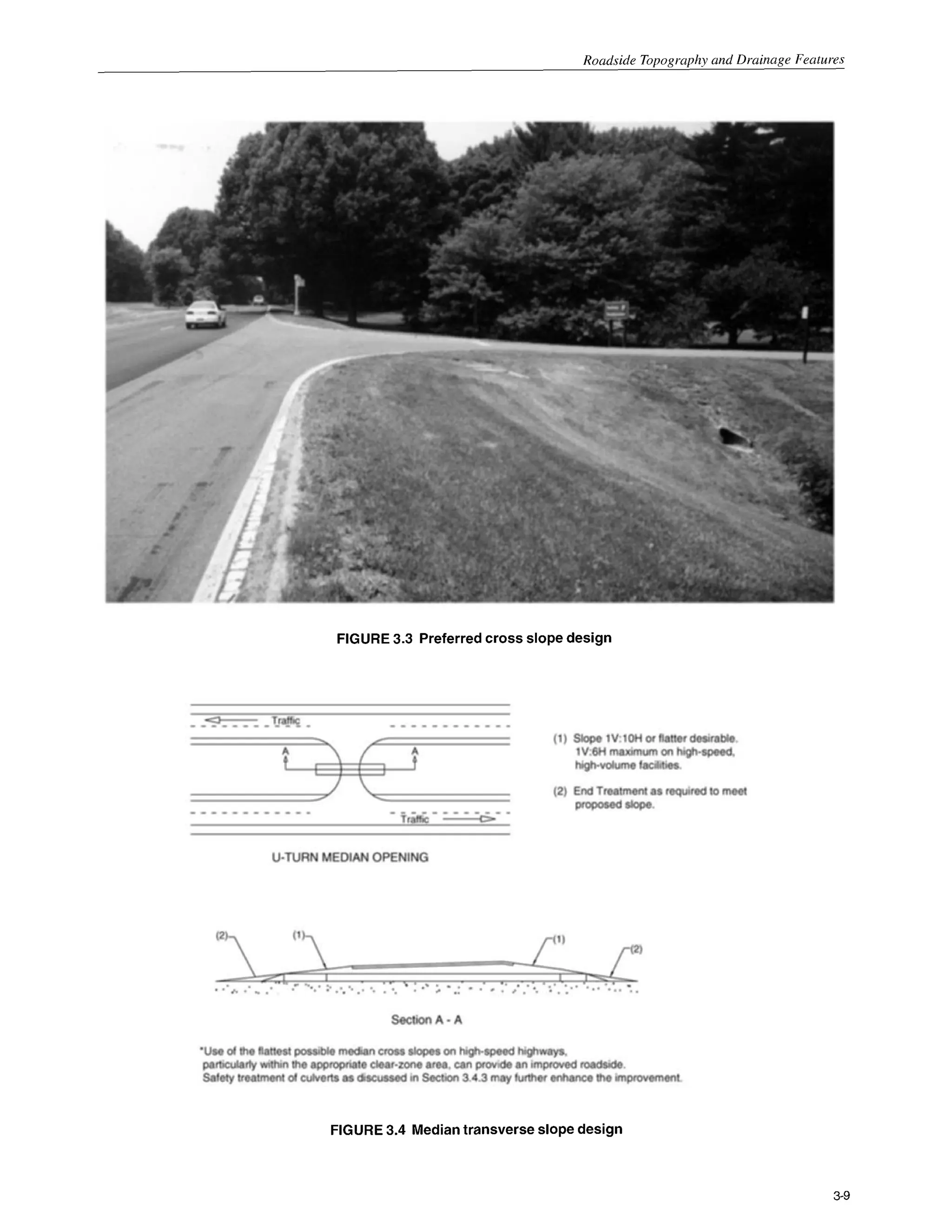
3.2 ROADSIDEGEOMETRY
If a roadsideis not flat, a motoristleavingtheroadway will
encounter a foreslope, a backslope, a transverse slope, or
a drainage channel (change in sideslope from a foreslope
to a backslope). Each of these features has an effect on a
vehicle’s lateral encroachment and trajectory as discussed
in the following sections.
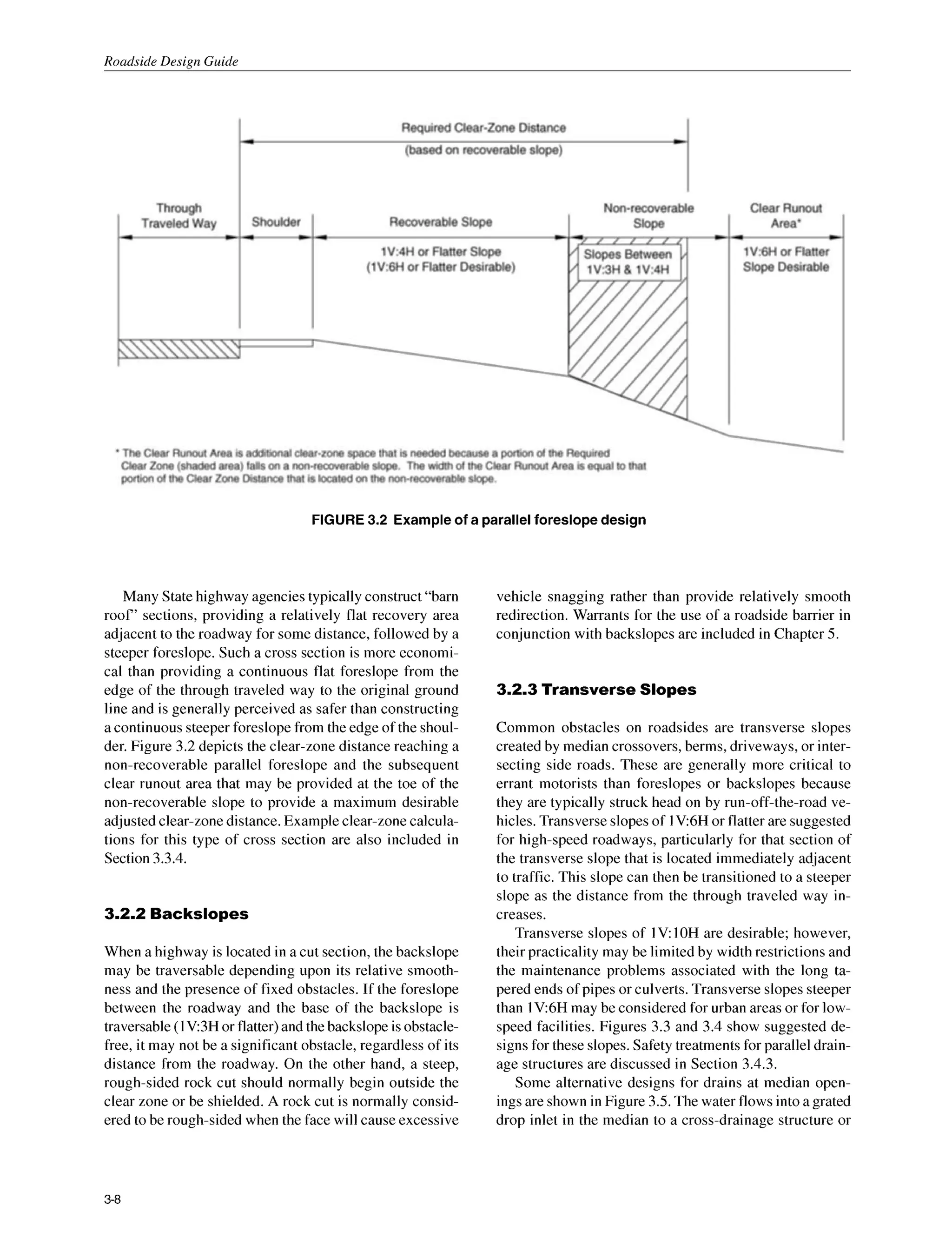
3.2.1 Foreslopes
Foreslopes parallel to the flow of traffic may be identified
as recoverable, non-recoverable, or critical. Recoverable
foreslopesare lV:4H or flatter.If such slopesarerelatively
smoothand traversable,the suggestedclear-zone distance
may be taken directly from Figure 3.1 or Table3.1. Motor-
ists who encroach on recoverable foreslopes can gener-
ally stop their vehicles or slow them enough to return to
the roadway safely. Fixed obstacles such as culvert
headwalls will normally not extend above the foreslope
withintheclear-zonedistance.Examplesof suggestedroad-
side design practices for recoverable foreslopes and the
application of the clear-zone concept are in Section 3.3.1.
A non-recoverable foreslope is defined as one that is
traversable, but from which most vehicles will be unable
to stop or to return to the roadway easily. Vehicles on
such slopes typically can be expected to reach the bot-
tom. Foreslopes between 1V:3H and 1V:4H generally fall
into this category. Since a high percentage of encroach-
ing vehicles will reach the toe of these slopes, the clear-
zone distance cannot logically end on the slope. Fixed
obstacles will normally not be constructed along such
slopes and a clear runout area at the base is desirable.
Section 3.3.2 discusses non-recoverable foreslopes. Ex-
ample C provides an example for a clear-zone computa-
tion.
A criticalforeslopeis one on which a vehicle is likely to
overturn.Foreslopessteeperthan 1V3H generally fall into
this category. If a foreslope steeper than 1V3H begins
closer to the through traveled way than the suggested
clear-zone distance for that specific roadway, a barrier
might be warranted if the slope cannot readily be flat-
tened. Barrierwarrants for criticalforeslopesare discussed
in Chapter 5.
3-2](https://image.slidesharecdn.com/2347692-250526105611-6c3d9c6b/75/Roadside-Design-Guide-2006-With-Updated-Chapter-6-3rd-Edition-Anita-Vandervalkostrander-27-2048.jpg)
![Roadside Tonoaranhv and Drainage Features
FIGURE 3.la Clear-zonedistancecurves [metric units]
3-3](https://image.slidesharecdn.com/2347692-250526105611-6c3d9c6b/75/Roadside-Design-Guide-2006-With-Updated-Chapter-6-3rd-Edition-Anita-Vandervalkostrander-28-2048.jpg)
![Roadside Design Guide
FIGURE 3.1b Clear-zone distance curves [U.S. customary units]
3-4](https://image.slidesharecdn.com/2347692-250526105611-6c3d9c6b/75/Roadside-Design-Guide-2006-With-Updated-Chapter-6-3rd-Edition-Anita-Vandervalkostrander-29-2048.jpg)
![Roadside Tonoaranhv and Drainage Features
1V:SHTO
1V:4H
2.0 - 3.0
3.5 - 4.5
4.5 - 5.0
5.0- 5.5
3.5 - 4.5
5.0- 6.0
6.0 - 8.0
7.5 - 8.5
4.5- 5.5
6.0- 7.5
7.5- 9.0
8.0- 10.0"
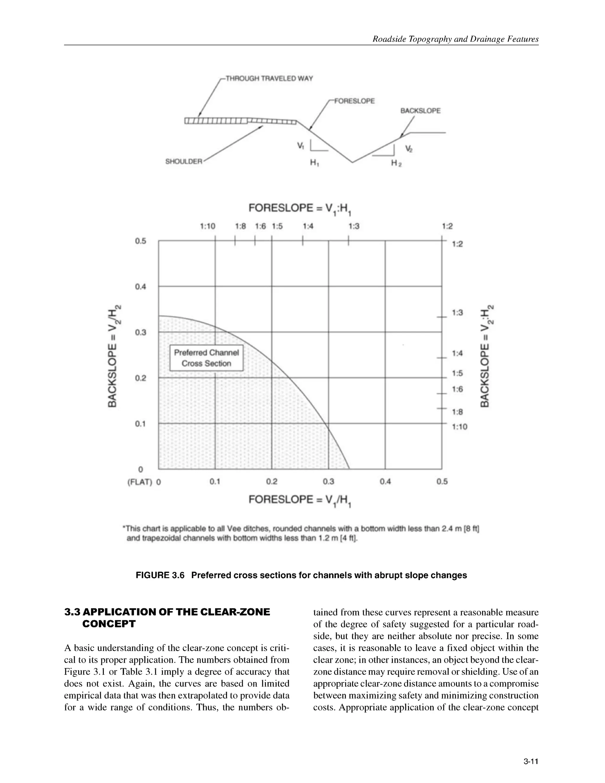
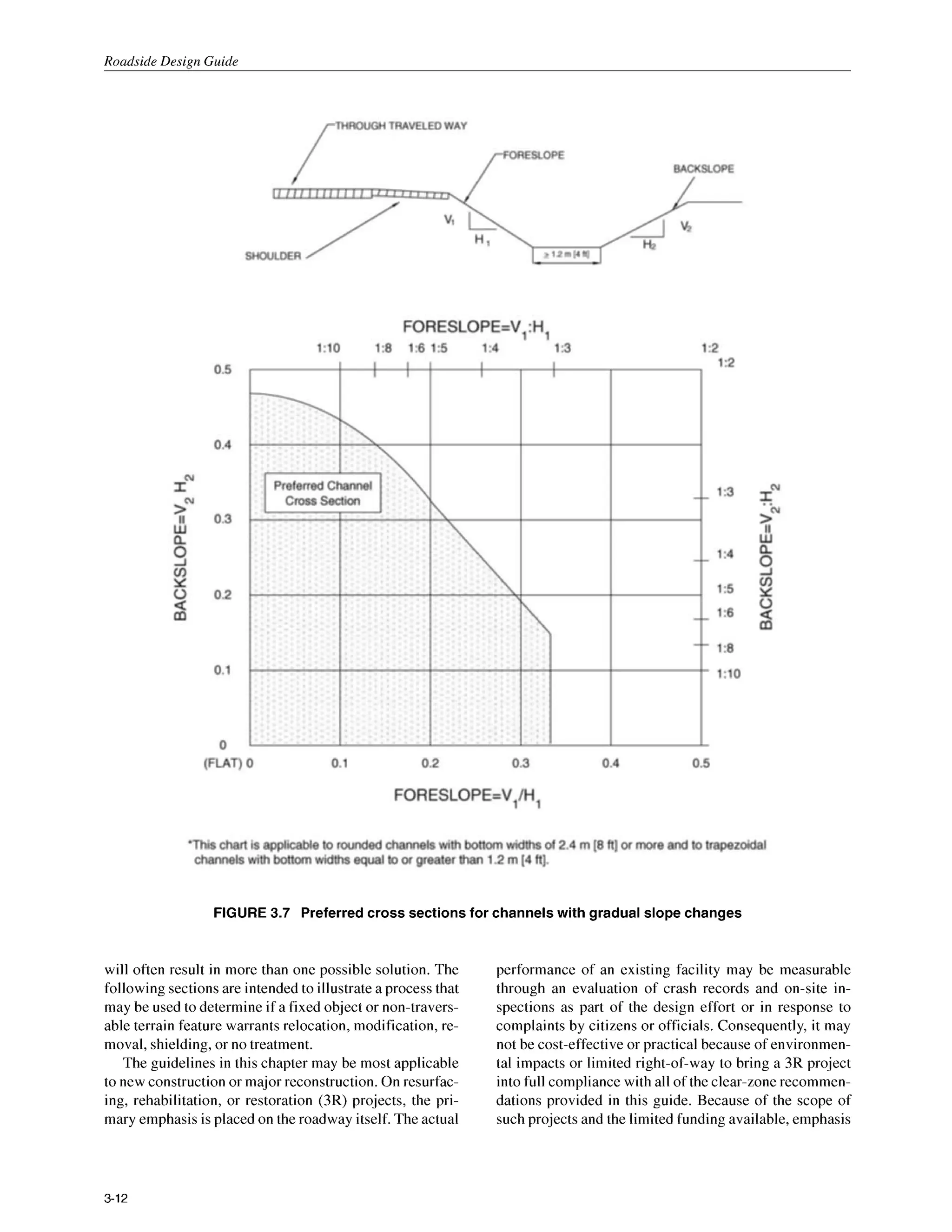
TABLE 3.1 Clear-zone distances in meters [feet] from edge of through traveled way
1V:3H
*+
*+
**
*+
*+
*+
**
*+
**
**
*+
**
DESIGN
SPEED
60 k d h
or
less
70-80
k d h
90
k d h
100
kmlh
110
kmlh
DESIGN
ADT
UNDER 750
750 - 1.500
1500 - 6000
OVER 6000
UNDER 750
750 - 1.500
1500 - 6000
OVER 6000
UNDER 750
750 - 1500
1500- 6000
OVER 6000
UNDER 750
750 - 1500
1500- 6000
OVER 6000
UNDER 750
750 - 1500
1500- 6000
OVER 6000
Metric Units
FORESLOPES
1V:6H
or flatter
2.0 - 3.0
3.0 - 3.5
3.5 - 4.5
4.5 - 5.0
3.0 - 3.5
4.5 - 5.0
5.0 - 5.5
6.0 - 6.5
3.5- 4.5
5.0- 5.5
6.0- 6.5
6.5- 7.5
5.0- 5.5
6.0- 7.5
8.0- 9.0
9.0- 10.0"
5.5- 6.0
7.5- 8.0
8.5- 10.0"
9.0- 10.5"
6.0- 7.5
8.0- 10.0"
10.0- 12.0"
11.0- 13.5"
6.0- 8.0
8.5- 1 1.O*
10.5- 13.0"
1 1 .5 - 14.0"
BACKSLOPES
1V:3H
2.0- 3.0
3.0- 3.5
3.5- 4.5
4.5- 5.0
2.5- 3.0
3.0- 3.5
3.5- 4.5
4.5- 5.0
2.5 - 3.0
3.0 - 3.5
4.5 - 5.0
5.0 - 5.5
3.0 - 3.5
3.5 - 4.5
4.5 - 5.5
6.0 - 6.5
3.0 - 3.5
3.5 - 5.0
5.0- 6.0
6.5- 7.5
1V:SHTO
1V:4H
2.0- 3.0
3.0- 3.5
3.5- 4.5
4.5- 5.0
2.5 - 3.0
3.5- 4.5
4.5- 5.0
5.5 - 6.0
3.0 - 3.5
4.5 - 5.0
5.0- 5.5
6.0 - 6.5
3.5 - 4.5
5.0 - 5.5
5.5 - 6.5
7.5 - 8.0
4.5 - 5.0
5.5 - 6.0
6.5 - 7.5
8.0- 9.0
1V:6H
or flatter
2.0- 3.0
3.0- 3.5
3.5- 4.5
4.5 - 5.0
3.0- 3.5
4.5 - 5.0
5.0- 5.5
6.0- 6.5
3.0 - 3.5
5.0- 5.5
6.0 - 6.5
6.5- 7.5
4.5 - 5.0
6.0 - 6.5
7.5 - 8.0
8.0 - 8.5
4.5 - 5.0
6.0 - 6.5
8.0 - 8.5
8.5 - 9.0
+ Where a site specific investigation indicates a high probability of continuing crashes, or such occurrences are indicated by crash
history, the designer may provide clear-zone distances greater than the clear-zone shown in Table 3.1. Clear zones may be limited to
9 m for practicality and to provide a consistent roadway template if previous experience with similar projects or designs indicates
satisfactory performance.
+*Since recovery is less likely on the unshielded, traversable 1V:3Hslopes, fixed objects should not be present in the vicinity of the toe
of these slopes. Recovery of high-speed vehicles that encroach beyond the edge of the shoulder may be expected to occur beyond the
toe of slope. Determination of the width of the recovery area at the toe of slope should take into consideration right-of-way
availability, environmental concerns, economic factors, safety needs, and crash histories. Also, the distance between the edge of the
through traveled lane and the beginning of the 1V:3Hslope should influence the recovery area provided at the toe of slope. While the
application may be limited by several factors, the foreslope parameters which may enter into determining a maximum desirable
recovery area are illustrated in Figure 3.2.
3-5](https://image.slidesharecdn.com/2347692-250526105611-6c3d9c6b/75/Roadside-Design-Guide-2006-With-Updated-Chapter-6-3rd-Edition-Anita-Vandervalkostrander-30-2048.jpg)
![Roadside Design Guide
DESIGN
ADT
UNDER 750
750 - 1500
1500-6000
OVER 6000
UNDER 750
750 - 1500
1500-6000
OVER 6000
DESIGN
SPEED
40 mph
or
less
45-50
mPh
55 mph
60 mph
1V:6H
or flatter
7- 10
10- 12
12-14
14- 16
10- 12
14- 16
16-18
20 - 22
65-70
mPh
1V:3H
7- 10
10- 12
12- 14
14- 16
8 - 10
10- 12
12- 14
14- 16
1V:5H TO
1V:4H
7- 10
10- 12
12- 14
14- 16
8 - 10
12- 14
14- 16
18-20
UNDER 750
750 - 1500
1500- 6000
OVER 6000
UNDER 750
750 - 1500
1500- 6000
OVER 6000
12- 14
16- 18
20 - 22
22 - 24
16- 18
20 - 24
26 - 30
30-32 *
TABLE 3.1 (Cont'd)
W.S. Customary Units]
IRESLOPE
1V:5H TO
1V:4H
7- 10
12- 14
14- 16
16- 18
12- 14
16-20
20 - 26
24 - 28
14- 18
20 - 24
24 - 30
26-32*
20 - 24
26-32*
32-40*
36-44*
20 - 26
28-36*
34-42 *
38-46*
1V:3H
**
**
**
**
**
**
**
**
**
**
**
**
**
**
**
**
**
**
**
**
10- 12
10- 12 14- 16
14- 16 16- 18
16- 18 20 - 22
10- 12 12- 14
12- 14 16- 18
14- 18 18-22
+
20 - 22 24 - 26
10- 12 14- 16
12- 16 18-20
16-20 22 - 24
22 - 24 26 - 30
1V:6H
or flatter
7- 10
10- 12
12- 14
14- 16
10- 12
14- 16
16- 18
20 - 22
10- 12
16- 18
20 - 22
22 - 24
14- 16
20 - 22
24 - 26
26 - 28
14- 16
20 - 22
26 - 28
28 - 30
* Where a site specific investigation indicates a high probability of continuing crashes, or such occurrences are indicated by crash
history, the designer may provide clear-zone distances greater than the clear-zone shown in Table 3.1. Clear zones may be limited to
30 ft for practicality and to provide a consistent roadway template if previous experience with similar projects or designs indicates
satisfactory performance.
** Since recovery is less likely on the unshielded, traversable 1V:3H slopes, fixed objects should not be present in the vicinity of the toe
of these slopes. Recovery of high-speed vehicles that encroach beyond the edge of the shoulder may be expected to occur beyond the
toe of slope. Determination of the width of the recovery area at the toe of slope should take into consideration right-of-way
availability, environmental concerns, economic factors, safety needs, and crash histories. Also, the distance between the edge of the
through traveled lane and the beginning of the 1V:3H slope should influence the recovery area provided at the toe of slope. While the
application may be limited by several factors, the foreslope parameters which may enter into determining a maximum desirable
recovery area are illustrated in Figure 3.2.
3-6](https://image.slidesharecdn.com/2347692-250526105611-6c3d9c6b/75/Roadside-Design-Guide-2006-With-Updated-Chapter-6-3rd-Edition-Anita-Vandervalkostrander-31-2048.jpg)
![Roadside Tonoaranhv and Drainage Features
TABLE 3.2 HorizontalCurveAdjustments
Kz(Curve Correction Factor) (Metric Units)
K,, (Curve Correction Factor) [U.S. Customary Units]
c z c = (Lc) (Kcz) Note: The clear-zone correction
factor is applied to the
outside of curves only.
Curves flatter than 900 m
[2860ft] do not require an
adjusted clear zone.
Where:
CZc = clear zone on outside of curvature, meters [feet]
Lc = clear-zone distance, meters [feet] (Figure 3.I or
Table 3.1)
Kcz = curve correction factor
3-7](https://image.slidesharecdn.com/2347692-250526105611-6c3d9c6b/75/Roadside-Design-Guide-2006-With-Updated-Chapter-6-3rd-Edition-Anita-Vandervalkostrander-32-2048.jpg)
![Roadside Design Guide
tion as designed if the vehicle is airborne or sliding side-
ways when contact is made. Non-yielding fixed objects
should be located beyond the clear-zone distance for these
cross sections as determined from Figure 3.1 or Table 3.1.
3.4 DRAINAGEFEATURES
Effective drainage is one of the most critical elements in
the design of a highway or street. However, drainage fea-
tures should be designed and built with consideration
given to their consequences on the roadside environment.
In addition to drainage channels, which were addressed
in Section 3.2.4, curbs, parallel and transverse pipes and
culverts, and drop inlets are common drainage system el-
ements that should be designed, constructed, and main-
tained with both hydraulic efficiency and roadside safety
in mind.
In general, the following options, listed in order of pref-
erence, are applicable to all drainage features:
eliminate non-essential drainage structures;
design or modify drainage structures so they are
traversable or present a minimal obstruction to
an errant vehicle;
if a major drainage feature cannot effectively be
redesigned or relocated, shield it using a suitable
traffic barrier if it is in a vulnerable location.
The remaining sections of this chapter identify the
safety problems associated with curbs,pipes and culverts,
and drop inlets, and offer recommendations concerning
the location and design of these features to improve their
safety characteristics without adversely affecting their
hydraulic capabilities.The information presented applies
to all roadway types and projects. However, as with many
engineering applications, the specific actions taken at a
given location often rely heavily on the exercise of good
engineering judgment and on a case-by-case assessment
of the costs and benefits associated with alternative de-
signs.
3.4.1 Curbs
Curbs are commonly used for drainagecontrol, pavement
edge support and delineation, right-of-way reduction, aes-
thetics, sidewalk separation, and reduction of maintenance
operations. Curb designs are classified as vertical or slop-
ing. Vertical curbs are defined as those having a vertical or
nearly vertical traffic face I50 mm [6in.] or higher. These
are intended to discourage motorists from deliberately
leaving the roadway. Sloping curbs are defined as those
having a sloping traffic face 150mm [6in.] or less in height.
These can be readily traversed by a motorist when neces-
sary, but a designer may prefer a height for sloping curbs
of no greater than 100 mm [4 in.] because higher curbs
may drag the underside of some vehicles.
In general, curbs are not desirable along high-speed
roadways. If a vehicle is spinning or slipping sideways as
it leaves the roadway, wheel contact with a curb could
cause it to trip and overturn. Under other impact condi-
tions, a vehicle may become airborne, which may result in
loss of control by the motorist. The distance over which a
vehicle may be airborne and the height above (or below)
normal bumper height attained after striking a curb may
become critical if secondary crashes occur with traffic
barriers or other roadside appurtenances.
If a curb is used in conjunction with a metal beam traf-
fic barrier, it should ideally be located flush with the face
of the railing or behind it. Where the curb height is 150mm
[6in.] or higher, the barrier should be stiffened to reduce
its deflection to avoid the potential of a vehicle vaulting
the rail. Curbs should not be used in front of sloping faced
concrete barriers because such placement may result in
unsatisfactory barrier performance. Curb/barrier combi-
nations, particularly for bridge railings, should be crash
tested if extensive use of the combination exists or is
planned and a similar combination has not been previ-
ously tested. Refer to Chapter 5, Section 5.6.2, “Terrain
Effects” for additional guidelines about curb usage with
traffic barriers. Also see Chapter 4 ofA Policy on Geomet-
ric Design ofHighwuys and Streets (2) for more informa-
tion on curb configuration and placement. A National
Cooperative Highway Research Program project, sched-
uled for completion in March 2003, is under way to de-
velop design guidelines for the use of curbs and curb-
barrier combinations.
When obstructions exist behind curbs, a minimum hori-
zontal clearance of 0.5 m [1.5ft] should be provided be-
yond the face of curbs to the obstructions. This offset
may be considered the minimum allowable horizontal clear-
ance (or operational offset), but it should not be con-
strued as an acceptable clear zone distance. Since curbs
do not have a significant redirectional capability, obstruc-
tions behind a curb should be located at or beyond the
minimum clear-zone distances shown in Table 3.I. In many
instances, it will not be feasible to obtain the recommended
clear zone distances on existing facilities. On new con-
struction where minimum recommended clear zones can-
not be provided, fixed objects should be located as far
from traffic as practical on a project-by-project basis, but
in no case closer than 0.5 m [1.5 ft] from the face of the
curb.
3-14](https://image.slidesharecdn.com/2347692-250526105611-6c3d9c6b/75/Roadside-Design-Guide-2006-With-Updated-Chapter-6-3rd-Edition-Anita-Vandervalkostrander-39-2048.jpg)
![Roadside Topography and Drainage Features
3.4.2 Cross-DrainageStructures
Cross-drainage structures are designed to carry water
underneath the roadway embankment and vary in size from
460 mm [18in.] for concrete or corrugated metal pipes to
3 m [10ft] or more for multibarreled concrete box culverts
or structural plate pipes. Typically, their inlets and outlets
consist of concreteheadwalls and wingwalls for the larger
structuresand beveled-end sections for the smallerpipes.
While these types of designs are hydraulically efficient
and minimize erosion problems, they may represent an
obstacle to motorists who run off the road. This type of
design may result in either a fixed object protruding above
an otherwise traversable embankment or an opening into
which a vehicle can drop, causing an abrupt stop. The
options available to a designer to minimize these obstacles
are:
use a traversable design;
extend the structure so that it is less likely to be
hit;
shield the structure;
delineate the structure if the above alternatives
are not appropriate.
Each of these options is discussed in the following
subsections.
3.4.2.1 Traversable Designs
A roadside designed with optimal safety features could
be defined as one that is almost flat, is completely travers-
able from the edge of the through traveled way to the
right-of-way line, and would include sufficient area for all
desirable clear-zone distance requirements. Such a facility
would resemble a landing strip or runway at an airport.
Thus, it is readily apparent from the start that roadside
design must be a series of compromises between “abso-
lute” safety and engineering, environmental, and economic
constraints. The designer should strive for embankments
as smooth or traversable as practical for a given facility.
As indicated in Sections 3.1 and 3.2, traversable, non-
recoverable foreslopes may be rounded at top and bottom
and may provide a relatively flat runout area at the bot-
tom.
If a foreslope is traversable, the preferred treatment for
any cross-drainage structure is to extend (or shorten) it to
intercept the roadway embankment and to match the inlet
or outlet slope to the foreslope. For small culverts, no
other treatment is required. For cross-drainagestructures,
a small pipe culvert is defined as a single round pipe with
a 900 mm [36in.] or less diameter or multiple round pipes
each with a 750 mm [30 in.] or less diameter. Extending
culverts to locate the inlets/outlets a fixed distance from
the through traveled way is not recommended if such treat-
ment introduces discontinuities in an otherwise travers-
able slope. Extending the pipe results in warping the
foreslopes in or out to match the opening, which pro-
duces a significantly longer area that affects the driver
who has run off the road. Matching the inlet to the
foreslope is desirable because it results in an extremely
small “target” to hit, reduces erosion problems, and sim-
plifies mowing operations.
Single structures and end treatments wider than 1 m
[3 ft] can be made traversable for passenger size vehicles
by using bar grates or pipes to reduce the clear opening
width. Modifications to the culvert ends to make them
traversable should not significantly decrease the hydrau-
lic capacity of the culvert. Safety treatments must be hy-
draulically efficient. In order to maintain hydraulic effi-
ciency, it may be necessary to apply bar grates to flared
wingwalls, flared end sections, or to culvert extensions
that are larger in size than the main barrel. The designer
should consider shielding the structure if significant hy-
draulic capacity or clogging problems could result.
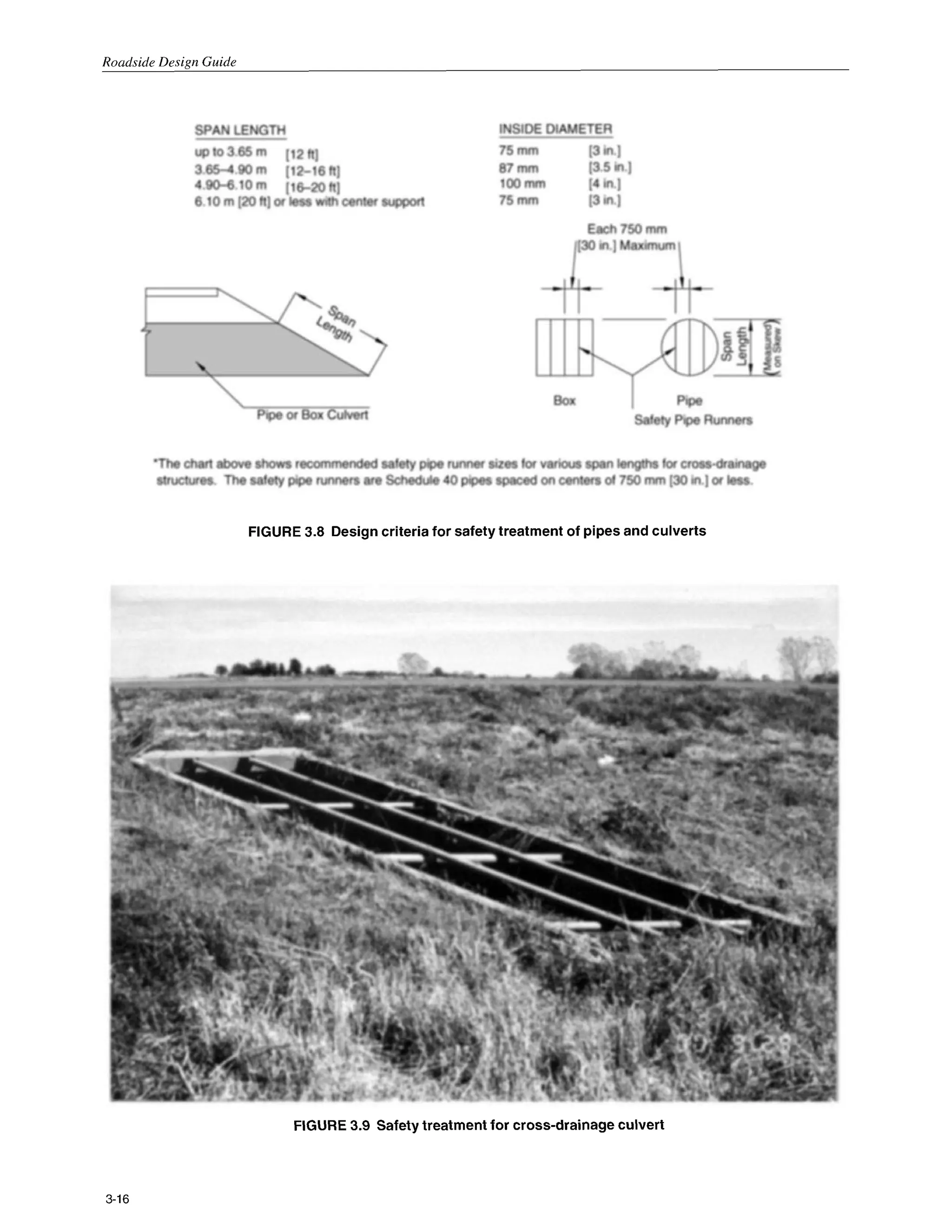
Full-scale crash tests have shown that automobilescan
cross grated-culvert end sections on slopes as steep as
lV:3H at speeds as low as 30km/h [20mph] and as high as
100 km/h [60 mph], when steel pipes spaced on 750 mm
[30 in.] centers are used for these cross-drainage struc-
tures. This spacing does not significantly change the flow
capacity of a pipe unless debris accumulates and causes
partial clogging of the inlet. This underscores the impor-
tance of accurately assessing the clogging potential of a
structure during design and the importance of keeping
the inlets free of debris. Figure 3.8 shows recommended
sizes to support a full-sized automobile, and is based on a
750mm [30in.] bar spacing. It is important to note that the
toe of the foreslope and the ditch or stream bed area imme-
diately adjacent to the culvert must be more or less tra-
versable if the use of a grate is to have any significant
safety benefit. Normally, grading within the right-of-way
limits can produce a satisfactory runout path.
For median drainage where flood debris is not a con-
cern and where mowing operations are frequently required,
much smaller openings between bars may be tolerated
and grates similar to those commonly used for drop inlets
may be appropriate. It should also be noted that both the
hydraulic efficiency and the roadside environment may
be improved by making the culverts continuous and add-
ing a median drainage inlet. This alternative eliminates
two end treatments and is usually a practical design when
neither median width nor height of fill are excessive. Fig-
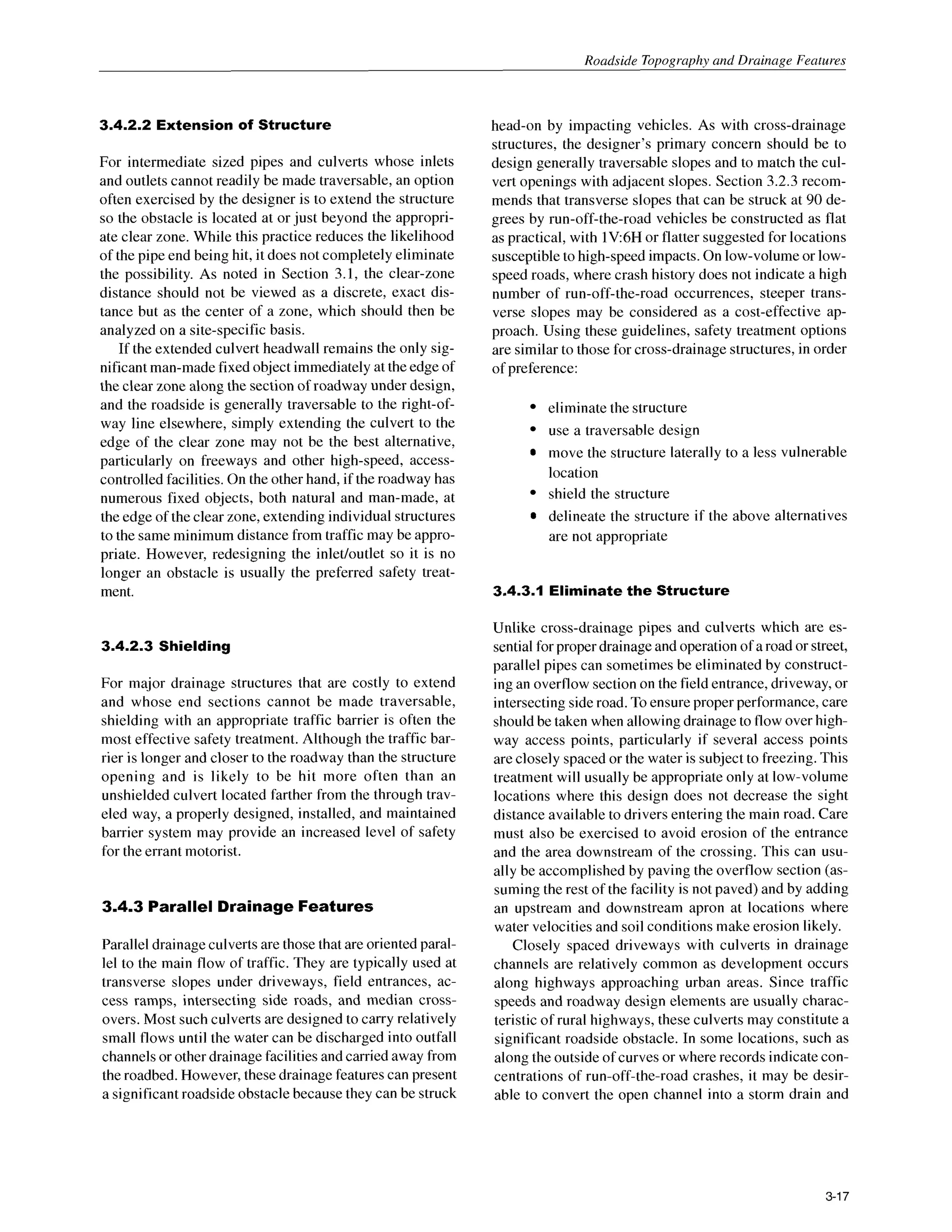
ure 3.9 shows a traversable pipe grate on a concrete box
culvert constructed to match the 1V6H side slope.
3-15](https://image.slidesharecdn.com/2347692-250526105611-6c3d9c6b/75/Roadside-Design-Guide-2006-With-Updated-Chapter-6-3rd-Edition-Anita-Vandervalkostrander-40-2048.jpg)
![Roadside Design Guide
FIGURE 3.10 InleVoutletdesign example for parallel drainage
backfill the areas between adjacent driveways. This treat-
ment will eliminate the ditch section as well as the trans-
verse slopes with pipe inlets and outlets.
3.4.3.2 Traversable Designs
As emphasized earlier in this chapter, transverse slopes
should be designed with consideration given to their ef-
fect on the roadside environment. The designer should
try to provide the flattest transverse slopes practical in
each situation, particularly in areas where the slope has
shown a high probability of being struck head-on by a
vehicle. Once this has been done, parallel drainage struc-
tures should match the selected transverse slopes and
should be safety treated if possible when they are located
in a vulnerable position relative to main road traffic. While
many of these structures are small and present a minimal
target, the addition of pipes and bars perpendicular to
traffic can reduce wheel snagging in the culvert opening.
Research has shown that, for parallel drainage structures,
a grate consisting of pipes set on 600 mm [24 in.] centers
will significantly reduce wheel snagging. It isrecommended
that the center of the bottom bar or pipe be set at 100 to
200 mm [4to 8 in.] above the culvert invert.
Generally, single pipes with diameters of 600mm [24
in.] or less will not require a grate. However, when a mul-
tiple pipe installation is involved, consideration of a grate
for smaller pipes may be appropriate. Reference may be
made to the Texas Transportation Institute Research Study
2-8-79-280, Safe End Treatmentfor Roadside Culverts (4),
in which researchers concluded that a passenger vehicle
should be able to traverse a pipe/slope combination at
speeds up to 80km/h [50mph] without rollover. To achieve
this result, both the roadway (or ditch) foreslope and the
driveway foreslope should be 1V:6H or flatter and have a
smooth transition between them. Ideally, the culvert should
be cut to match the driveway slope and fitted with cross
members perpendicular to the direction of traffic flow as
described above. This study suggests that it could be
cost-effective to flatten the approach slopes to lV:6H and
match the pipe openings to these slopes for all sizes of
pipes up to 900mm [36in.]in diameter for traffic volumes
above 100vehicles per day. The addition of grated inlets
to these pipes was considered cost-effective for pipes 900
mm [36 in.] or greater for ADTs over 500, and for pipes
over 600 mm [24 in.] in diameter for traffic volumes over
13,000vehicles per day. Because these numbers were based
in part on assumptions by the researchers, they should be
interpreted as approximations and not as absolute num-
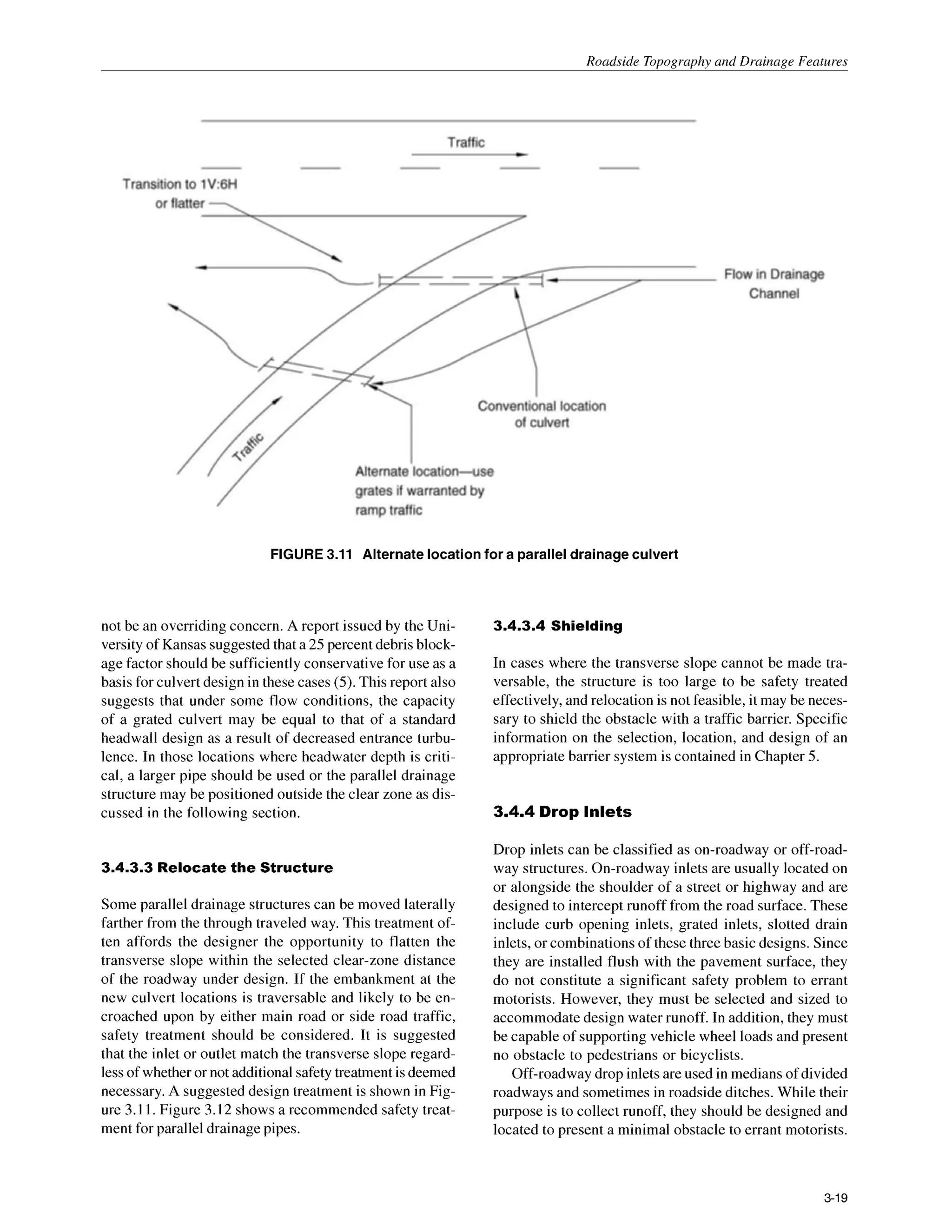
bers. Figure 3.10 illustrates a possible design for the inlet
and outlet end of a parallel culvert. When channel grades
permit, the inlet end may use a drop-inlet type design to
reduce the length of grate required.
The recommended grate design may affect culvert ca-
pacity if significant blockage by debris is likely; however,
because capacity is not normally the governing design
criteria for parallel structures, hydraulic efficiency may
3-18](https://image.slidesharecdn.com/2347692-250526105611-6c3d9c6b/75/Roadside-Design-Guide-2006-With-Updated-Chapter-6-3rd-Edition-Anita-Vandervalkostrander-43-2048.jpg)
![Roadside Design Guide
FIGURE3.12 Safetytreatment for parallel drainage pipe
This can be accomplished by building these features flush
with the channel bottom or slope on which they are lo-
cated. No portion of the drop inlet should project more
than 100 mm [4 in.] above the ground line. The opening
should be treated to prevent a vehicle wheel from drop-
ping into it; but unless pedestrians are a consideration,
grates with openings as small as those used for pavement
drainage are not necessary. Neither is it necessary to de-
sign for a smooth ride over the inlet. It is sufficient to
prevent wheel snagging and the resultant sudden decel-
eration or loss of control associated with it.
REFERENCES
1. AASHO.Highway Design and OperationalPrac-
tices Related to Highway Design. American As-
sociation of State Highway Officials, Washing-
ton, DC, 1967.
2. AASHTO. Guide for Selecting, Locating and
Designing Traffic Barriers. American Associa-
tion of State Highway and Transportation Offi-
cials, Washington, DC, 1977.
3. AASHTO. A Policy on Geometric Design o
f
Highways and Streets. American Association of
State Highway and Transportation Officials,
Washington,DC, 2001.
4. Texas Transportation Institute. Research Study
2-8-79-280: Safe End Treatments for Roadside
Culverts.
5. University of Kansas. Development of Hydrau-
lic Design Chartsfor Type IV End Sections for
Pipe Culverts. KU-93-5. 1993.
3-20](https://image.slidesharecdn.com/2347692-250526105611-6c3d9c6b/75/Roadside-Design-Guide-2006-With-Updated-Chapter-6-3rd-Edition-Anita-Vandervalkostrander-45-2048.jpg)
![Roadside Tonoaranhv and Drainage Features
EXAMPLE A
Design ADT: 4000
Design Speed: 100km/h [60mph]
Recommended clear-zone distance for 1V:5H foreslope: 10m to 12 m [32 ft to 40 ft] (from Table 3.1)
Discussion: The available recovery area of 8.4 m [28 ft] is less than the recommended 10 m to 12 m [32 ft to 40 ft].
If the culvert headwall is greater than 100mm [4 in.] in height and is the only obstruction on an otherwise traversable
foreslope, it should be removed and the inlet modified to match the lV:5H foreslope. If the foreslope contains rough
outcroppings or boulders and the headwall does not significantly increase the obstruction to a motorist, the decision to
do nothing may be appropriate. A review of the highway’s crash history, if available, may be made to determine the
nature and extent of vehicle encroachments and to identify any specific locations that may require special treatment.
3-21](https://image.slidesharecdn.com/2347692-250526105611-6c3d9c6b/75/Roadside-Design-Guide-2006-With-Updated-Chapter-6-3rd-Edition-Anita-Vandervalkostrander-46-2048.jpg)
![Roadside Design Guide
EXAMPLE B
Design ADT: 300
Design Speed: 60 k d h [40 mph]
Recommended clear-zone distance for 1V:lOH slope: 2 m to 3 m [7 ft to 10ft] (from Table 3.1)
Discussion: The available clear-zone distance is 1.8 m [6ft], 0.2 m to 1.2 m [I ft to 4 ft] less than the recommended
recovery area. When an area has a significant number of run-off-the-road crashes, it may be appropriate to consider
shielding or removing the entire row of trees within the crash area. If this section of road has no significant history of
crashes and is heavily forested with most of the other trees only slightly farther from the road, this tree would
probably not require treatment. If, however, none of the other trees are closer to the roadway than, for example, 4.5 m
[15 ft], this individual tree represents a more significant obstruction and should be considered for removal. If a tree
were 4.5 m [15 ft] from the edge of through traveled way, and all or most of the other trees were 7.5 m [25 ft] or
more, its removal may still be appropriate. This example emphasizes that the clear-zone distance is an approximate
number at best and that individual objects should be analyzed in relation to other nearby obstacles.
3-22](https://image.slidesharecdn.com/2347692-250526105611-6c3d9c6b/75/Roadside-Design-Guide-2006-With-Updated-Chapter-6-3rd-Edition-Anita-Vandervalkostrander-47-2048.jpg)
![Roadside Tonoaranhv and Drainage Features
EXAMPLE C
Design ADT: 7000
Design Speed: I00 k d h [60mph]
Recommended clear-zone distance for 1V:lOH foreslope: 9 to 10m [30to 32 ft] (from Table 3.1)
Recommended clear-zone distance for 1V:SH foreslope: 9 to 10m [30 to 32 ft] (from Table 3.I )
Available recovery distance before breakpoint of non-recoverableforeslope: 5 m [17 ft]
Clear runout area at toe of foreslope: 9 to 10m [30to 32 ft] minus 5 m [17 ft] or 4 to 5 m [13to I7 ft]
Discussion: Since the non-recoverable foreslope is within the required clear-zone distance of the 1V: IOH foreslope,
a runout area beyond the toe of the non-recoverable foreslope is desirable. Using the steepest recoverable foreslope
before or after the non-recoverable foreslope, a clear-zone distance is selected from Figure 3.I or Table 3.1. In this
example, the 1V:8H foreslope beyond the base of the fill dictates a 9 to 10 m [30 to 32 ft] clear-zone distance. Since
5 m [17 ft] are availableat the top, an additional4 to 5 m [13 to 17 ft] could be provided at the bottom. All foreslope
breaks may be rounded and no fixed objects would normally be built within the upper or lower portions of the clear-
zone or on the intervening foreslope.
It may be practical to provide less than the entire 4 to 5 m [13 to 17 ft] at the toe of the non-recoverable foreslope. A
smaller recovery area could be applicable based on the rounded foreslope breaks, the flatter 1V:IOH foreslope at the
top, or past crash histories. A specific site investigation may be appropriate in determining an approximate runout
area beyond the toe of the non-recoverable foreslope.
3-23](https://image.slidesharecdn.com/2347692-250526105611-6c3d9c6b/75/Roadside-Design-Guide-2006-With-Updated-Chapter-6-3rd-Edition-Anita-Vandervalkostrander-48-2048.jpg)
![Roadside Design Guide
EXAMPLE D
Design ADT: 12,000
Design Speed: 1 10km/h [70 mph]
Recommended clear-zone distance for 1V:6H foreslope: 9 to 10.5m [30 to 34 ft] (from Table 3.1)
Discussion: Since the critical foreslope is only 7 m [23 ft] from the through traveled way, instead of the suggested 9
to 10.5 m [30 to 34 ft], it should be flattened if practical or considered for shielding. However, if this is an isolated
obstacle and the roadway has no significant crash history, it may be appropriate to do little more than delineate the
drop off in lieu of foreslope flattening or shielding.
Although a "weighted" average of the foreslopes may be used, a simple average of the clear-zone distances for each
foreslope is accurate enough if the variable foreslopes are approximately the same width. If one foreslope is
significantly wider, the clear-zone computation based on that foreslope alone may be used.
EXAMPLE E
Design ADT: 350
Design Speed: 60 km/h [40 mph]
Recommended clear-zone distance for 1V:5H foreslope: 2 m to 3 m [7 ft to 10ft] (from Table 3.1)
Discussion: The available 1.5m [4.5 ft] is 0.5 m to I .5 m [2.5 ft to 5.5 ft] less than the recommended recovery area.
If much of this roadway has a similar cross section and no significant run-off-the-road crash history, neither foreslope
flattening nor a traffic barrier would be recommended. On the other hand, even if the 1V5H foreslope were 3 m
[lo ft] wide and the clear-zone requirement were met, a traffic barrier might be appropriate if this location has
noticeably less recovery area than the rest of the roadway and the embankment was unusually high.
3-24](https://image.slidesharecdn.com/2347692-250526105611-6c3d9c6b/75/Roadside-Design-Guide-2006-With-Updated-Chapter-6-3rd-Edition-Anita-Vandervalkostrander-49-2048.jpg)
![Roadside Topography and Drainage Features
EXAMPLE F
Design ADT: 5000
Design Speed: 100km/h [60mph]
Recommended clear-zone distance for 1V:SH foreslope: 8 m to 9 m [26 ft to 30 ft] (from Table 3.1)
Recommended clear-zone distance for 1V:5H foreslope: 10m to 12 m [32 ft to 40 ft] (from Table 3.1)
Discussion: The 1V:8H foreslope and the 1V:5H foreslope may be averaged taking into account the distance
available on each foreslope. The distance (6 m [20 ft]) along the 1V:8H slope is multiplied by the slope of 1/8 (V/H).
The distance (5 m [17 ft]) along the l V 5 H foreslope is multiplied by the slope of 1/5. The resulting distances are
added together and divided into the sum of the two distances (6 m [20 ft] plus 5 m [17 ft]) available. The result is an
“average” foreslope which may be used in Figure 3.1 or Table 3.1. For sections flatter than or equal to lV:lOH, a
slope of 1V:1OH is used. Decimal results of 0.5 or greater may be rounded up to the next even numbered slope while
decimal results less than 0.5 may be rounded down to the next even numbered slope. The calculations are given
below:
1.
2.
3.
4.
5.
6 m [20 ft] x (1/8) + 5 m [ 17 ft] x (1/5) = 1.75 m [5.9 ft]
6 m [20 ft] +5 m [17 ft] = 11 m [37 ft]
11 m [37 ftlA.75 m [5.9ft] = 6.3rounded to 6
Enter Table 3.1 for the 1V:6H or flatter slopes
The clear-zone distance from Table 3.1 is 8 m to 9 m [26 ft to 30 ft] for the given speed and traffic
volume. Since the example has 11 m [37 ft] available on the two foreslopes, it is acceptable without
further treatment.
In this example, it would be desirable to have no fixed objects constructed on any part of the l V 5 H foreslope.
Natural obstacles such as trees or boulders at the toe of the slope would not be shielded or removed. However, if the
final foreslope were steeper than 1V:4H, a clear runout area should be considered at the toe of the foreslope. The
designer may choose to limit the clear-zone distance to 9 m [30 ft] if that distance is consistent with the rest of the
roadway template, a crash analysis or site investigation does not indicate a potential run-off-the-road problem in this
area, and the distance selected does not end at the toe of the non-recoverable foreslope.
3-25](https://image.slidesharecdn.com/2347692-250526105611-6c3d9c6b/75/Roadside-Design-Guide-2006-With-Updated-Chapter-6-3rd-Edition-Anita-Vandervalkostrander-50-2048.jpg)
![Roadside Design Guide
EXAMPLE G
Design ADT: 1400
Design Speed: 100km/h [60 mph]
Recommended clear-zone distance for 1V:6H foreslope (fill): 6 to 7.5 m [20 to 24 ft] (from Table 3.1)
Recommended clear-zone distance for 1V:4H backslope (cut): 5 to 5.5 m [I6 to I8 ft] (from Table 3.1)
Discussion: For channels within the preferred cross-section area of Figures 3.6 or 3.7, the clear zone may be
determined from Figure 3.1 or Table 3.1. However, when the recommended clear zone exceeds the available clear
zone for the foreslope, an adjusted clear zone may be determined as follows:
I. Calculate the percentage of the recommended clear-zone range available from the edge of through traveled way
to the PVI of the foreslope (4.5 m /6 x 100 = 75% and 4.5 m / 7.5 x 100= 60% [14.5 ft / 20 ft x 100 = 73% and
14.5ft / 24 ft x 100= 60 %I).
Subtract these percentages from 100%and multiply results by the recommended range of clear zones for the
backslope (100%-75%) x 5 m = 1.25 m ,and (100%- 60%) x 5.5 m = 2.2 m [(loo%- 73%) x 16 ft = 4.3 ft and
(100%- 60%) x I8 ft = 7.2 ft]. The range of required clear zone on the backslope is 1.25 m to 2.2 m [4.3 to 7.2
ft].
Add the available clear zone on the foreslope to the range of values determined in Step 2 (4.5 m + I .25 m = 5.75
m and 4.5 m + 2.2 m = 6.7 m [14.5 ft + 4.3 ft = 18.8 ft and 14.5 ft + 7.2 ft = 21.7 ft]). The adjusted clear-zone
range is 5.75 to 6.7 meters [18.8 to 21.7 ft].
2.
3.
Because the tree is located beyond the adjusted clear zone, removal is not required. Removal should be considered if
this one obstacle is the only fixed object this close to the through traveled way along a significant length.
To determine the recommended clear zone for the foreslope in the trapezoidal channel, an average foreslope must be
calculated. See Example F for the method of foreslope averaging.
Drainage channels not having the preferred cross section (see Figure 3.6 or 3.7) should be located at or beyond the
clear zone. However, backslopes steeper than 1V:3H are typically located closer to the roadway. If these slopes are
relatively smooth and unobstructed, they present little safety problem to an errant motorist. If the backslope consists
of a rough rock cut or outcropping, shielding may be warranted as discussed in Chapter 5.
3-26](https://image.slidesharecdn.com/2347692-250526105611-6c3d9c6b/75/Roadside-Design-Guide-2006-With-Updated-Chapter-6-3rd-Edition-Anita-Vandervalkostrander-51-2048.jpg)
![Roadside Tonoaranhv and Drainage Features
EXAMPLE H
Design ADT: 800
Design Speed: 80 km/h [50mph]
Recommended clear-zone distance for 1V:4H foreslope: 5 m to 6 m [16 ft to 20 ft] (from Table 3.1)
Discussion: The ditch is not within the preferred cross section area of Figure 3.6 and is 0.6 m to 1.8 m [2 ft to 6 ft]
less than the recommended clear-zone distance. However, if the ditch bottom and backslope are free of obstacles, no
additional improvement is suggested. A similar cross section on the outside of a curve where encroachments are
more likely and the angle of impact is sharper would probably be flattened if practical.
EXAMPLE I
Design ADT: 3000
Design Speed: 100k d h [60 mph]
Recommended clear-zone distance for 1V:6H foreslope: 8.0 to 9.0 m [26 to 30 ft] (from Table 3.1)
Discussion: The rock cut is within the given clear-zone distance but would probably not warrant removal or
shielding unless the potential for snagging, pocketing, or overturning a vehicle is high. Steep backslopes are clearly
visible to motorists during the day, thus lessening the risk of encroachments. Roadside delineation of sharper than
average curves through cut sections can be an effective countermeasure at locations having a significant crash history
or potential.
3-27](https://image.slidesharecdn.com/2347692-250526105611-6c3d9c6b/75/Roadside-Design-Guide-2006-With-Updated-Chapter-6-3rd-Edition-Anita-Vandervalkostrander-52-2048.jpg)
![Roadside Design Guide
4.1 ACCEPTANCECRITERIA FOR
BREAKAWAYSUPPORTS
The term “breakaway support” refers to all types of sign,
luminaire, and traffic signal supports that are designed to
yield when impacted by a vehicle. The release mechanism
may be a slip plane, plastic hinge, fracture element, or a
combination of these. The criteria used to determine if a
support is considered breakaway are found in Reference 1
and NCHRP Report 350, Recommended Procedures for
the Safety Peg7ormance Evaluation o
f Highway Features
(2).Breakaway support hardware previously found ac-
ceptable under the requirements of either the 1985or 1994
editions of the AASHTO Standard Specifications for
Structural Supportsfor Highway Signs, Luminaires and
Traffic Signals (1) are acceptable under NCHRP Report
350guidelines. TheFederal Highway Administration main-
tains lists of acceptable, crashworthy supports.
These criteria require that a breakaway support fail in a
predictable manner when struck head-on by an 820 kg
[1,800lb] vehicle, or its equivalent, at speeds of 35 km/h
[20mph] and 100kmh [60mph]. It is desirable to limit the
longitudinal component of the occupant impact velocity
to 3.0 m/s [10ft/s]; but values as high as 5.0m/s [16ft/s]
are considered acceptable. These specifications also es-
tablish a maximum stub height of 100mm [4 in.] to lessen
the possibility of snagging the undercarriage of a vehicle
after a support has broken away from its base.
In addition to the change in velocity criterion, satisfac-
tory breakaway support performance dependson the crash
vehicle remaining upright during and after the impact with
no significant deformation or intrusion of the passenger
compartment. The appropriateprocedures for acceptance
testing of breakaway supports are described in NCHRP
Report 350.
Full-scale crash tests, bogie tests, and pendulum tests
are used in the acceptance testing of breakaway devices.
In full-scale testing, an actual vehicle is accelerated to the
test speed and impacted into the device being tested. The
point of initial impact is the front of the vehicle, either
centered or at the quarter point of the bumper. Full-scale
tests produce the most accurate results; however, their
main disadvantage is cost. Bogie vehicles are also used to
test breakaway hardware. A bogie is a reusable, adjust-
able surrogate vehicle used to model actual vehicles. A
nose, similar to a pendulum nose, is used to duplicate the
crush characteristicsof the vehicle being modeled. Bogie
vehicles are designed to be used in the speed range of 35
to 100km/h [20to 60mph].
To reduce testing costs, pendulum tests are also used
to evaluate breakaway hardware. Pendulum nose sections
have been developed that model the fronts of vehicles.
Pendulum tests have typically been used to test luminaire
support hardware. However, due to the physical limita-
tions of pendulums, pendulum testing is limited to
35 km/h [20 mph] impacts. Pendulum test results for im-
pacts at 35 km/h [20mph] may be extrapolated to predict
100km/h [60mph] impact behavior providing the support
breaks free with little or no bending in the support. This
extrapolation method should not be used with base-bend-
ing or yielding supports.
4.2 DESIGN AND LOCATION CRITERIA FOR
BREAKAWAYAND NON-BREAKAWAY
SUPPORTS
Sign, luminaire, and similar supports must first be struc-
turally adequate to support the device mounted on them
and to resist ice and wind loads as specified in the
AASHTO Standard Specifications for Structural Sup-
portsfor Highway Signs, Luminaires and Traffic Signals
(1). Other concerns are that they be properly designed
and carefully located to ensure that the breakaway de-
vices perform properly and to minimize the likelihood of
impacts by errant vehicles. For example, supports should
not be placed in drainageditches where erosion and freez-
ing might affect the proper operation of the breakaway
mechanism. It is also possible that a vehicle entering the
ditch might be inadvertently guided into the support. Signs
and supports that are not needed should be removed. If a
sign is needed, then it should be located where it is least
likely to be hit. Whenever possible, signs should be placed
behind existing roadside barriers (beyond the design de-
flection distance), on existing structures, or in similar non-
accessible areas. If this cannot be achieved, then breakaway
supportsshould be used. Only when the use of breakaway
supportsis not practicable should a traffic barrier or crash
cushion be used exclusively to shield sign supports.
As a general rule, breakaway supports should be used
unless an engineering study indicates otherwise. How-
ever, concern for pedestrian involvement has led to the
use of fixed supports in some urban areas. Examples of
sites where breakaway supports may be imprudent are
adjacent to bus shelters or in areas of extensive pedes-
trian concentrations.
Supports placed on roadside slopes must not allow
impacting vehicles to snag on either the foundation or
any substantial remains of the support. Surrounding ter-
rain must be graded to permit vehicles to pass over any
non-breakaway portion of the installation that remains in
the ground or rigidly attached to the foundation. Figure
4.1, adopted from the AASHTO Standard Specifications
for Structural Supports for Highway Signs, Luminaires
and TraflicSignals (I), illustrates the method used to mea-
sure the required 100mm [4 in.] maximum stub height.
Breakaway support mechanisms are designed to func-
tion properly when loaded primarily in shear. Most mecha-
nisms are designed to be impacted at bumper height, typi-
cally about 500 mm [20in.] above the ground. If impacted
4-2](https://image.slidesharecdn.com/2347692-250526105611-6c3d9c6b/75/Roadside-Design-Guide-2006-With-Updated-Chapter-6-3rd-Edition-Anita-Vandervalkostrander-54-2048.jpg)