2
2
2
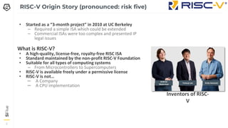
RISC-V Origin Story(pronounced: risk five)
• Started as a “3-month project” in 2010 at UC Berkeley
– Required a simple ISA which could be extended
– Commercial ISAs were too complex and presented IP
legal issues
What is RISC-V?
• A high-quality, license-free, royalty-free RISC ISA
• Standard maintained by the non-profit RISC-V Foundation
• Suitable for all types of computing systems
– From Microcontrollers to Supercomputers
• RISC-V is available freely under a permissive license
• RISC-V is not…
– A Company
– A CPU implementation
Yunsup Lee Krste Asanovic
Andrew
Waterman
Inventors of RISC-
V
3.
3
3
3
RISC-V Foundation –riscv.org
• RISC-V Foundation is a non-profit
organization formed in August
2015 to publicly govern the ISA
• Foundation Functions
– Directs future development of ISA
– Compliance tests
– Promotion of the ISA
• >350 members representing a
wide range of markets
5
5
5
• User Mode- version 2.2 Ratified
– Frozen in 2014 at version 2.0
– Updates since 2.0:
• CSR and FENCE.I instructions moved out
of base extension “I”
• Memory model clarifications
• Privilege Mode - version 1.11
Ratified
– Version 1.11 ratified May 2019
• Debug Spec - version 0.13 Ratified
• Specifications in Progress
– Hypervisor Extension - version 0.3 Draft
– Vector Extension - version 0.7 Draft
– And many more
• Participate - https://riscv.org
– Join the mailing list
– Become a member
Status of the RISC-V Specifications
7
7
7
RISC-V Instruction SetArchitectures
• RISC-V uses a standard naming convention to
describe the ISAs supported in a given
implementation
• ISA Name format: RV[###][abc…..xyz]
– RV – Indicates a RISC-V architecture
– [###] - {32, 64, 128} indicate the width of the
integer register file and the size of the user
address space
– [abc…xyz] – Used to indicate the set of
extensions supported by an implementation.
8.
8
8
8
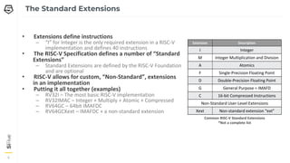
The Standard Extensions
•Extensions define instructions
– “I” for Integer is the only required extension in a RISC-V
implementation and defines 40 instructions
• The RISC-V Specification defines a number of “Standard
Extensions”
– Standard Extensions are defined by the RISC-V Foundation
and are optional
• RISC-V allows for custom, “Non-Standard”, extensions
in an implementation
• Putting it all together (examples)
– RV32I – The most basic RISC-V implementation
– RV32IMAC – Integer + Multiply + Atomic + Compressed
– RV64GC – 64bit IMAFDC
– RV64GCXext – IMAFDC + a non-standard extension
Extension Description
I Integer
M Integer Multiplication and Division
A Atomics
F Single-Precision Floating Point
D Double-Precision Floating Point
G General Purpose = IMAFD
C 16-bit Compressed Instructions
Non-Standard User-Level Extensions
Xext Non-standard extension “ext”
Common RISC-V Standard Extensions
*Not a complete list
9.
9
9
9
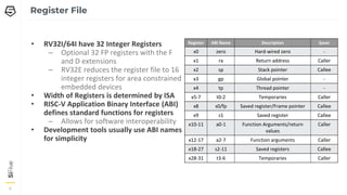
Register File
• RV32I/64Ihave 32 Integer Registers
– Optional 32 FP registers with the F
and D extensions
– RV32E reduces the register file to 16
integer registers for area constrained
embedded devices
• Width of Registers is determined by ISA
• RISC-V Application Binary Interface (ABI)
defines standard functions for registers
– Allows for software interoperability
• Development tools usually use ABI names
for simplicity
Register ABI Name Description Saver
x0 zero Hard-wired zero -
x1 ra Return address Caller
x2 sp Stack pointer Callee
x3 gp Global pointer -
x4 tp Thread pointer -
x5-7 t0-2 Temporaries Caller
x8 s0/fp Saved register/Frame pointer Callee
x9 s1 Saved register Callee
x10-11 a0-1 Function Arguments/return
values
Caller
x12-17 a2-7 Function arguments Caller
x18-27 s2-11 Saved registers Callee
x28-31 t3-6 Temporaries Caller
10.
10
10
10
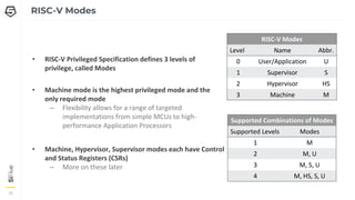
RISC-V Modes
• RISC-VPrivileged Specification defines 3 levels of
privilege, called Modes
• Machine mode is the highest privileged mode and the
only required mode
– Flexibility allows for a range of targeted
implementations from simple MCUs to high-
performance Application Processors
• Machine, Hypervisor, Supervisor modes each have Control
and Status Registers (CSRs)
– More on these later
RISC-V Modes
Level Name Abbr.
0 User/Application U
1 Supervisor S
2 Hypervisor HS
3 Machine M
Supported Combinations of Modes
Supported Levels Modes
1 M
2 M, U
3 M, S, U
4 M, HS, S, U
15
15
15
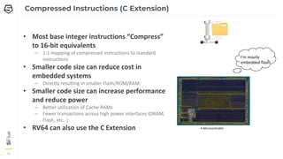
Compressed Instructions (CExtension)
• Most base integer instructions “Compress”
to 16-bit equivalents
– 1:1 mapping of compressed instructions to standard
instructions
• Smaller code size can reduce cost in
embedded systems
– Directly resulting in smaller Flash/ROM/RAM
• Smaller code size can increase performance
and reduce power
– Better utilization of Cache RAMs
– Fewer transactions across high power interfaces (DRAM,
Flash, etc…)
• RV64 can also use the C Extension
I’m mostly
embedded flash
A Microcontroller
14.
16
16
16
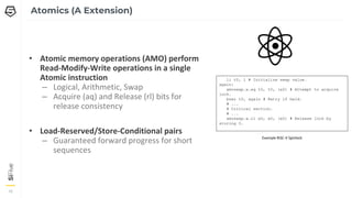
Atomics (A Extension)
•Atomic memory operations (AMO) perform
Read-Modify-Write operations in a single
Atomic instruction
– Logical, Arithmetic, Swap
– Acquire (aq) and Release (rl) bits for
release consistency
• Load-Reserved/Store-Conditional pairs
– Guaranteed forward progress for short
sequences
li t0, 1 # Initialize swap value.
again:
amoswap.w.aq t0, t0, (a0) # Attempt to acquire
lock.
bnez t0, again # Retry if held.
# ...
# Critical section.
# ...
amoswap.w.rl x0, x0, (a0) # Release lock by
storing 0.
Example RISC-V Spinlock
15.
17
17
17
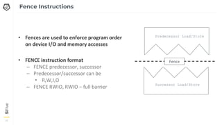
Fence Instructions
• Fencesare used to enforce program order
on device I/O and memory accesses
• FENCE instruction format
– FENCE predecessor, successor
– Predecessor/successor can be
• R,W,I,O
– FENCE RWIO, RWIO – full barrier
Predecessor Load/Store
Fence
Successor Load/Store
16.
18
18
18
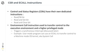
CSR and ECALLInstructions
• Control and Status Registers (CSRs) have their own dedicated
instructions :
– Read/Write
– Read and Set bit
– Read and Clear bit
• Environment Call instruction used to transfer control to the
execution environment and a higher privileged mode
– Triggers a synchronous Interrupt (discussed later)
– Example: User mode program can use an ECALL to transfer control to
a Machine mode OS kernel, aka System Call
20
20
20
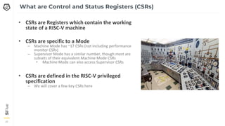
What are Controland Status Registers (CSRs)
• CSRs are Registers which contain the working
state of a RISC-V machine
• CSRs are specific to a Mode
– Machine Mode has ~17 CSRs (not including performance
monitor CSRs)
– Supervisor Mode has a similar number, though most are
subsets of their equivalent Machine Mode CSRs
• Machine Mode can also access Supervisor CSRs
• CSRs are defined in the RISC-V privileged
specification
– We will cover a few key CSRs here
19.
21
21
21
Identification CSRs
• misa– Machine ISA Register
– Reports the ISA supported by the hart (i.e.
RV32IMAC)
• mhartid – Machine hart ID
– Integer ID of the Hardware Thread
• mvendorid – Machine Vendor ID
– JEDEC Vendor ID
• marchid – Machine Architecture ID
– Used along with mvendorid to identify a
implementation. No format specified
• mimpid - Machine Implementation ID
– Implementation defined format
20.
22
22
22
Machine Status (mstatus)- The Most Important CSR
Control and track the hart’s current operating state
Bits Field Name Description
0 UIE User Interrupt Enable
1 SIE Supervisor Interrupt Enable
2 Reserved
3 MIE Machine Interrupt Enable
4 UPIE User Previous Interrupt Enable
5 SPIE Supervisor Previous Interrupt Enable
6 Reserved
7 MPIE Machine Previous Interrupt Enabler
8 SPP Supervisor Previous Privilege
[10:9] Reserved
[12:11] MPP Machine Previous Privilege
Bits Field Name Description
[14:13] FS Floating Point State
[16:15] XS User Mode Extension State
17 MPRIV Modify Privilege (access memory as MPP)
18 SUM Permit Supervisor User Memory Access
19 MXR Make Executable Readable
20 TVM Trap Virtual memory
21 TW Timeout Wait (traps S-Mode wfi)
22 TSR Trap SRET
[23:30] Reserved
[31] SD State Dirty (FS and XS summary bit)
RV32 mstatus CSR
21.
23
23
23
Timer CSRs
• mtime
–RISC-V defines a requirement
for a counter exposed as a
memory mapped register
– There is no frequency
requirement on the timer, but
• It must run at a constant
frequency
• The platform must expose
frequency
Bits Field Name Description
[63:0] mtime Machine Time Register
Bits Field Name Description
[63:0] mtimecmp Machine Time Compare Register
mtime CSR mtimecmp CSR
• mtimecmp
– RISC-V defines a memory
mapped timer compare
register
– Triggers an interrupt when
mtime is greater than or
equal to mtimecmp
22.
24
24
24
Supervisor CSRs
• Mostof the Machine mode CSRs have
Supervisor mode equivalents
– Supervisor mode CSRs can be used to control the
state of Supervisor and User Modes.
– Most equivalent Supervisor CSRs have the same
mapping as Machine mode without Machine
mode control bits
– sstatus, stvec, sip, sie, sepc, scause, satp, and
more
• satp - Supervisor Address Translation and
Protection Register
– Used to control Supervisor mode address
translation and protection
Bits Field Name Description
[21:0] PPN Physical Page Number of the root page table
[30:22] ASID Address Space Identifier
31 MODE MODE=1 uses Sv32 Address Translation
RV32 satp CSR
Bits Field Name Description
[43:0] PPN Physical Page Number of the root page table
[59:44] ASID Address Space Identifier
[63:60] MODE Encodings for Sv32, Sv39, Sv48
RV64 satp CSR
23.
25
25
25
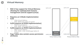
Virtual Memory
• RISC-Vhas support for Virtual Memory
allowing for sophisticated memory
management and OS support (Linux)
• Requires an S-Mode implementation
• Sv32
– 32bit Virtual Address
– 4KiB, 4MiB page tables (2 Levels)
• Sv39 (requires an RV64 implementation)
– 39bit Virtual Address
– 4KiB, 2MiB, 1GiB page tables (3 Levels)
• Sv48 (requires an RV64 implementation)
– 48bit Virtual Address
– 4KiB, 2MiB, 1 GiB, 512GB page tables (4
Levels)
• Page Tables also contain access permission
attributes
0xFFFF_FFFF
0x0000_0000
Virtual
Address
Virtual Address Map
0xFFFF_FFFF
0x0000_0000
Physical
Address
Physical Address Map
24.
26
26
26
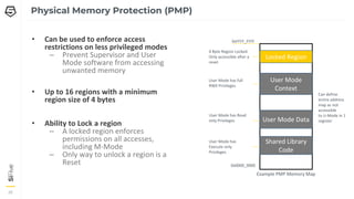
Physical Memory Protection(PMP)
• Can be used to enforce access
restrictions on less privileged modes
– Prevent Supervisor and User
Mode software from accessing
unwanted memory
• Up to 16 regions with a minimum
region size of 4 bytes
• Ability to Lock a region
– A locked region enforces
permissions on all accesses,
including M-Mode
– Only way to unlock a region is a
Reset
Locked Region
User Mode
Context
User Mode Data
0xFFFF_FFFF
0x0000_0000
4 Byte Region Locked.
Only accessible after a
reset
User Mode has full
RWX Privileges
User Mode has Read
only Privileges
Shared Library
Code
User Mode has
Execute only
Privileges
Example PMP Memory Map
Can define
entire address
map as not
accessible
to U-Mode in 1
register
28
28
28
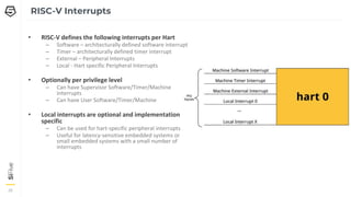
• RISC-V definesthe following interrupts per Hart
– Software – architecturally defined software interrupt
– Timer – architecturally defined timer interrupt
– External – Peripheral Interrupts
– Local - Hart specific Peripheral Interrupts
• Optionally per privilege level
– Can have Supervisor Software/Timer/Machine
Interrupts
– Can have User Software/Timer/Machine
• Local interrupts are optional and implementation
specific
– Can be used for hart-specific peripheral interrupts
– Useful for latency-sensitive embedded systems or
small embedded systems with a small number of
interrupts
RISC-V Interrupts
27.
29
29
29
Machine Status (mstatus)– As it relates to Interrupts
Bits Field Name Description
0 UIE User Interrupt Enable
1 SIE Supervisor Interrupt Enable
2 Reserved
3 MIE Machine Interrupt Enable
4 UPIE User Previous Interrupt Enable
5 SPIE Supervisor Previous Interrupt Enable
6 Reserved
7 MPIE Machine Previous Interrupt Enabler
8 SPP Supervisor Previous Privilege
[10:9] Reserved
[12:11] MPP Machine Previous Privilege
Bits Field Name Description
[14:13] FS Floating Point State
[16:15] XS User Mode Extension State
17 MPRIV Modify Privilege (access memory as MPP)
18 SUM Permit Supervisor User Memory Access
19 MXR Make Executable Readable
20 TVM Trap Virtual memory
21 TW Timeout Wait (traps S-Mode wfi)
22 TSR Trap SRET
[23:30] Reserved
[31] SD State Dirty (FS and XS summary bit)
RV32 mstatus CSR
• M/S/U IE – Global Interrupt Enables for Modes which supports interrupts
• M/S/U PIE – Encodes the state of interrupt enables prior to an interrupt.
– These bits can also be written to in order to enable interrupts when returning to lower privilege modes
• M/S PP – Encodes the privilege level prior to the previous interrupt
– These bits can also be written to in order to enter a lower privilege mode when executing MRET or SRET instructions
28.
30
30
30
Machine Interrupt CauseCSR (mcause)
• Interrupts are identified by reading the
mcause CSR
• The interrupt field determines if a trap
was caused by an interrupt or an
exception
Interrupt = 1 (interrupt)
Exception
Code
Description
0 User Software Interrupt
1 Supervisor Software Interrupt
2 Reserved
3 Machine Software Interrupt
4 User Timer Interrupt
5 Supervisor Timer Interrupt
6 Reserved
7 Machine Timer Interrupt
8 User External Interrupt
9 Supervisor External Interrupt
10 Reserved
11 Machine External Interrupt
12 - 15 Reserved
≥16 Local Interrupt X
Interrupt = 0 (exception)
Exception
Code
Description
0 Instruction Address Misaligned
1 Instruction Access Fault
2 Illegal Instruction
3 Breakpoint
4 Load Address Misaligned
5 Load Access Fault
6 Store/AMO Address Misaligned
7 Store/AMO Access Fault
8 Environment Call from U-mode
9 Environment Call from S-mode
10 Reserved
11 Environment Call from M-
mode
12 Instruction Page Fault
13 Load Page Fault
14 Reserved
15 Store/AMO Page Fault
≥16 Reserved
Bits Field Name Description
XLEN-1 Interrupt Identifies if an interrupt was
synchronous or asynchronous
[XLEN-2:0] Exception Code Identifies the exception
mcause CSR
29.
31
31
31
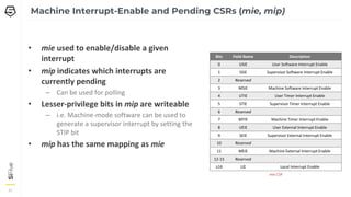
• mie usedto enable/disable a given
interrupt
• mip indicates which interrupts are
currently pending
– Can be used for polling
• Lesser-privilege bits in mip are writeable
– i.e. Machine-mode software can be used to
generate a supervisor interrupt by setting the
STIP bit
• mip has the same mapping as mie
Machine Interrupt-Enable and Pending CSRs (mie, mip)
Bits Field Name Description
0 USIE User Software Interrupt Enable
1 SSIE Supervisor Software Interrupt Enable
2 Reserved
3 MSIE Machine Software Interrupt Enable
4 UTIE User Timer Interrupt Enable
5 STIE Supervisor Timer Interrupt Enable
6 Reserved
7 MTIE Machine Timer Interrupt Enable
8 UEIE User External Interrupt Enable
9 SEIE Supervisor External Interrupt Enable
10 Reserved
11 MEIE Machine External Interrupt Enable
12-15 Reserved
≥16 LIE Local Interrupt Enable
mie CSR
30.
32
32
32
mtvec sets theBase interrupt vector and the interrupt Mode
• mtvec.Mode = Direct
– All Interrupts trap to the address mtvec.Base
– Software must read the mcause CSR and react accordingly
• mtvec.Vectored
– Interrupts trap to the address mtvec.Base + (4*mcause.ExCode)
– Eliminates the need to read mcause for asynchronous exceptions
Machine Trap Vector CSR (mtvec)
Bits Field Name Description
[XLEN-1:6] Base Machine Trap Vector Base Address.
64-byte Alignment
[1:0] Mode MODE Sets the interrupt processing
mode.
mtvec CSR
mtvec Modes
Value Name Description
0x0 Direct All Exceptions set PC to mtvec.BASE
Requires 4-Byte alignment
0x1 Vectored Asynchronous interrupts set pc to
mtvec.BASE + (4×mcause.EXCCODE)
Requires 4-Byte alignment
> 0x01 Reserved
31.
33
33
33
• On entry,the RISC-V hart will
– Save the current state
– Then set PC = mtvec, mstatus.MIE = 0
• MRET instruction restores state
Trap Handler – Entry and Exit
• Typical trap handler software will
PC
Priv
MIE
MEPC
mstatus.MPP
mstatus.MPIE
Push Registers
…
interrupt = mcause.msb
if interrupt
branch isr_handler[mcause.code]
else
branch exception_handler[mcause.code]
…
Pop Registers
MRET
Interrupt handler pseudo code
mtevc.MODE = Direct
PC
Priv
MIE
MEPC
mstatus.MPP
mstatus.MPIE
32.
34
34
34
.align 2
.global trap_entry
trap_entry:
addisp, sp, -16*REGBYTES
//store ABI Caller Registers
STORE x1, 0*REGBYTES(sp)
STORE x5, 2*REGBYTES(sp)
…
STORE x30, 14*REGBYTES(sp)
STORE x31, 15*REGBYTES(sp)
//call C Code Handler
call handle_trap
//restore ABI Caller Registers
LOAD x1, 0*REGBYTES(sp)
LOAD x5, 2*REGBYTES(sp)
…
LOAD x30, 14*REGBYTES(sp)
LOAD x31, 15*REGBYTES(sp)
addi sp, sp, 16*REGBYTES
mret
Interrupt Handler Code
void handle_trap()
{
unsigned long mcause = read_csr(mcause);
if (mcause & MCAUSE_INT) {
//mask interrupt bit and branch to handler
isr_handler[mcause & MCAUSE_CAUSE] ();
} else {
//branch to handler
exception_handler[mcause]();
}
}
//write trap_entry address to mtvec
write_csr(mtvec, ((unsigned long)&trap_entry));
RISC-V Assembly interrupt handler
to Push and Pop register file
C Code Handler determines interrupt cause and branches to the appropriate
function
33.
35
35
35
• Pushing andPopping Registers in Assembly
is a pain
• The interrupt attribute was added to GCC
to facilitate interrupt handlers written
entirely in C
– Interrupt functions only saves/restores
necessary registers onto the stack
– Align function on an 8-byte boundary
– Calles MRET after popping register file back
off the stack
Compiler Interrupt Attribute
void handle_trap(void) __attribute((interrupt));
void handle_trap()
{
unsigned long mcause = read_csr(mcause);
if (mcause & MCAUSE_INT) {
//mask interrupt bit and branch to handler
isr_handler[mcause & MCAUSE_CAUSE] ();
} else {
//synchronous exception, branch to handler
exception_handler[mcause & MCAUSE_CAUSE]();
}
}
//write handle_trap address to mtvec
write_csr(mtvec, ((unsigned long)&handle_trap));
Interrupt handler with interrupt attribute.
No assembly Code necessary
34.
CONFIDENTIAL – COPYRIGHT2018 SIFIVE. ALL RIGHTS RESERVED.
36
36
36
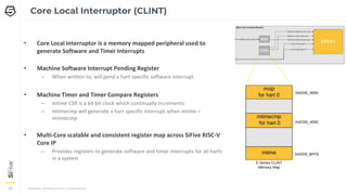
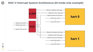
Core Local Interruptor (CLINT)
• Core Local Interruptor is a memory mapped peripheral used to
generate Software and Timer Interrupts
• Machine Software Interrupt Pending Register
– When written to, will pend a hart specific software interrupt
• Machine Timer and Timer Compare Registers
– mtime CSR is a 64 bit clock which continually increments
– mtimecmp will generate a hart specific interrupt when mtime =
mtimecmp
• Multi-Core scalable and consistent register map across SiFive RISC-V
Core IP
– Provides registers to generate software and timer interrupts for all harts
in a system
35.
37
37
37
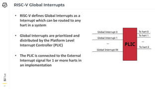
• RISC-V definesGlobal Interrupts as a
Interrupt which can be routed to any
hart in a system
• Global Interrupts are prioritized and
distributed by the Platform Level
Interrupt Controller (PLIC)
• The PLIC is connected to the External
Interrupt signal for 1 or more harts in
an implementation
RISC-V Global Interrupts
36.
CONFIDENTIAL – COPYRIGHT2018 SIFIVE. ALL RIGHTS RESERVED.
38
38
38
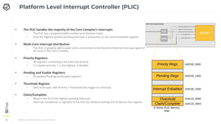
Platform Level Interrupt Controller (PLIC)
• The PLIC handles the majority of the Core Complex’s Interrupts
– The PLIC has a programmable number prioritization levels
– Only the highest priority pending interrupt is presented on the claim/complete register
• Multi-Core interrupt distribution
– The PLIC is globally addressable and is connected to the Machine External Interrupt signal of
all cores in the Core Complex
• Priority Registers
– 4B registers containing 3-bit interrupt priority
– 1 is lowest priority, 7 is the highest, 0 disables
• Pending and Enable Registers
– Bit packed Pending and Enable registers
• Threshold Register
– Only interrupts with Priority > Threshold will trigger an interrupt
• Claim/Complete
– Returns the ID of the highest pending interrupt
– Interrupt completion is signaled to the PLIC by software writing the ID back to this register
37.
39
39
39
• In thisexample an interrupt is presented to the PLIC
• The PLIC signals an interrupt to a hart using the Machine External Interrupt (interrupt 11)
• The interrupt handler (handle_trap) branches to the defined function to handle the Machine External Interrupt
– C Code placed the address of machine_external_interrupt function in location 11 of the async_handler vector table
• The machine_external_interrupt handler does the following:
– Reads the PLIC’s claim/complete register to determine highest priority pending interrupt
– Uses another vector table to branch to the interrupt’s specific handler
– Completes the interrupt by writing the interrupt number back to the PLIC’s claim/complete
PLIC Interrupt Code Example
void handle_trap(void) __attribute((interrupt));
void handle_trap()
{
unsigned long mcause = read_csr(mcause);
if (mcause & MCAUSE_INT) {
//mask interrupt bit and branch to handler
isr_handler[mcause & MCAUSE_CAUSE] ();
} else {
//synchronous exception, branch to handler
exception_handler[mcause & MCAUSE_CAUSE]();
}
}
//install PLIC handler at MEIP Location
isr_handler[11] = machine_external_interrupt;
//write trap_entry address to mtvec
write_csr(mtvec, ((unsigned long)&handle_trap));
void machine_external_interrupt()
{
//get the highest priority pending PLIC interrupt
uint32_t int_num = plic.claim_comlete;
//branch to handler
plic_handler[int_num]();
//complete interrupt by writing interrupt number
back to PLIC
plic.claim_complete = int_num;
}
38.
CONFIDENTIAL – COPYRIGHT2018 SIFIVE. ALL RIGHTS RESERVED.
40
40
40
RISC-V Interrupt System Architecture (M-mode only example)
42
42
42
Vector Extension Origin- Hwacha
• RISC-V (2010) originally designed to
explore new accelerators based on top
of vector engine (ESP)
• Hwacha was primary research vehicle to
develop vector ISA and
microarchitecture ideas (2012)
– Hwacha taped out multiple times at
UCB (v4.5 on EagleX)
– Hwacha was an explicitly decoupled
vector-fetch accelerator with own
vector instruction stream
RISC-V “V” extension has more traditional
single instruction stream, a la original Cray
vectors
https://www2.eecs.berkeley.edu/Pubs/TechRpts/2015/EECS-2015-264.pdf
41.
43
43
43
RISC-V Vector ExtensionHistory
• First proposal (v0.1) presented June 2015
workshop
• Many iterations until recent v0.7 stable draft
in Jan 2019
– v0.7 now being targeted by community
with implementation work and software
development
– Stable spec version v0.7.1, matching
software release!
• By far the largest RISC-V extension (larger
than sum of everything previously ratified)
https://github.com/riscv/riscv-v-spec
42.
44
44
RISC-V Foundation VectorExtension Overview
v0[0]
v1[0]
v31[0]
v0[1]
v1[1]
v31[1]
V0[VLMAX-1]
v1[VLMAX-1]
v31[VLMAX-1]
32 vector
registers
vtype
vl
Vector length CSR sets number of
elements active in each instruction
Vtype sets width of element in each
vector register (e.g., 16-bit, 32-bit, …)
Maximum vector length (VLMAX) depends on implementation,
number of vector registers used, and type of each element.
• Unit-stride, strided, scatter-gather, structure load/store
instructions
• Rich set of integer, fixed-point, and floating-point instructions
• Vector-vector, vector-scalar, and vector-immediate instructions
• Multiple vector registers can be combined to form longer vectors
to reduce instruction bandwidth or support mixed-precision
operations (e.g., 16b*16b->32b multiply-accumulate)
• Designed for extension with custom datatypes and widths
vstart
Resumption element after trap
Vector
CSRs
fcsr (vxrm/vxsat)
Fixed-point rounding mode and
saturation flag fields in FP CSR
43.
45
45
45
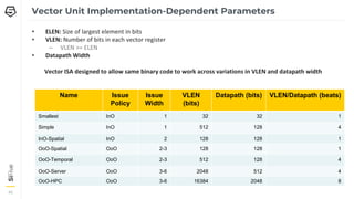
Vector Unit Implementation-DependentParameters
• ELEN: Size of largest element in bits
• VLEN: Number of bits in each vector register
– VLEN >= ELEN
• Datapath Width
Vector ISA designed to allow same binary code to work across variations in VLEN and datapath width
Name Issue
Policy
Issue
Width
VLEN
(bits)
Datapath (bits) VLEN/Datapath (beats)
Smallest InO 1 32 32 1
Simple InO 1 512 128 4
InO-Spatial InO 2 128 128 1
OoO-Spatial OoO 2-3 128 128 1
OoO-Temporal OoO 2-3 512 128 4
OoO-Server OoO 3-6 2048 512 4
OoO-HPC OoO 3-6 16384 2048 8
44.
46
46
Example - 32-bitVector Add
# vector-vector add routine of 32-bit integers
# void vvaddint32(size_t n, const int*x, const int*y, int*z)
# { for (size_t i=0; i<n; i++) { z[i]=x[i]+y[i]; } }
#
# a0 = n, a1 = x, a2 = y, a3 = z
# Non-vector instructions are indented
vvaddint32:
vsetvli t0, a0, e32 # Set vector length based on 32-bit vectors
vlw.v v0, (a1) # Get first vector
sub a0, a0, t0 # Decrement number done
slli t0, t0, 2 # Multiply number done by 4 bytes
add a1, a1, t0 # Bump pointer
vlw.v v1, (a2) # Get second vector
add a2, a2, t0 # Bump pointer
vadd.vv v2, v0, v1 # Sum vectors
vsw.v v2, (a3) # Store result
add a3, a3, t0 # Bump pointer
bnez a0, vvaddint32 # Loop back
ret # Finished
45.
47
47
Example - SAXPY
#void
# saxpy(size_t n, const float a, const float *x, float *y)
# { size_t i; for (i=0; i<n; i++) { y[i] = a * x[i] + y[i];}}
#
# register arguments:
# a0 n
# fa0 a
# a1 x
# a2 y
saxpy:
vsetvli a4, a0, e32, m8 # Set vector length based on 32-bit vectors, Vlmul x8
vlw.v v0, (a1) # Get first vector x[i]
sub a0, a0, a4 # Decrement count
slli a4, a4, 2 # Multiply length by 4 vector elements
add a1, a1, a4 # Increment pointer
vlw.v v8, (a2) # Get second vector y[i]
vfmacc.vf v8, fa0, v0 # Fused Multiply Accumulate v8 = (fa0 * v0) + v8
vsw.v v8, (a2) # Store result
add a2, a2, a4 # Increment pointer
bnez a0, saxpy # Loop Back
ret # Finished


![7
7
7
RISC-V Instruction Set Architectures
• RISC-V uses a standard naming convention to
describe the ISAs supported in a given
implementation
• ISA Name format: RV[###][abc…..xyz]
– RV – Indicates a RISC-V architecture
– [###] - {32, 64, 128} indicate the width of the
integer register file and the size of the user
address space
– [abc…xyz] – Used to indicate the set of
extensions supported by an implementation.](https://image.slidesharecdn.com/riscv-250724130518-2f937d43/85/riscv-overview-with-new-latest-specs-pdf-7-320.jpg)

![22
22
22
Machine Status (mstatus) - The Most Important CSR
Control and track the hart’s current operating state
Bits Field Name Description
0 UIE User Interrupt Enable
1 SIE Supervisor Interrupt Enable
2 Reserved
3 MIE Machine Interrupt Enable
4 UPIE User Previous Interrupt Enable
5 SPIE Supervisor Previous Interrupt Enable
6 Reserved
7 MPIE Machine Previous Interrupt Enabler
8 SPP Supervisor Previous Privilege
[10:9] Reserved
[12:11] MPP Machine Previous Privilege
Bits Field Name Description
[14:13] FS Floating Point State
[16:15] XS User Mode Extension State
17 MPRIV Modify Privilege (access memory as MPP)
18 SUM Permit Supervisor User Memory Access
19 MXR Make Executable Readable
20 TVM Trap Virtual memory
21 TW Timeout Wait (traps S-Mode wfi)
22 TSR Trap SRET
[23:30] Reserved
[31] SD State Dirty (FS and XS summary bit)
RV32 mstatus CSR](https://image.slidesharecdn.com/riscv-250724130518-2f937d43/85/riscv-overview-with-new-latest-specs-pdf-20-320.jpg)
![23
23
23
Timer CSRs
• mtime
– RISC-V defines a requirement
for a counter exposed as a
memory mapped register
– There is no frequency
requirement on the timer, but
• It must run at a constant
frequency
• The platform must expose
frequency
Bits Field Name Description
[63:0] mtime Machine Time Register
Bits Field Name Description
[63:0] mtimecmp Machine Time Compare Register
mtime CSR mtimecmp CSR
• mtimecmp
– RISC-V defines a memory
mapped timer compare
register
– Triggers an interrupt when
mtime is greater than or
equal to mtimecmp](https://image.slidesharecdn.com/riscv-250724130518-2f937d43/85/riscv-overview-with-new-latest-specs-pdf-21-320.jpg)
![24
24
24
Supervisor CSRs
• Most of the Machine mode CSRs have
Supervisor mode equivalents
– Supervisor mode CSRs can be used to control the
state of Supervisor and User Modes.
– Most equivalent Supervisor CSRs have the same
mapping as Machine mode without Machine
mode control bits
– sstatus, stvec, sip, sie, sepc, scause, satp, and
more
• satp - Supervisor Address Translation and
Protection Register
– Used to control Supervisor mode address
translation and protection
Bits Field Name Description
[21:0] PPN Physical Page Number of the root page table
[30:22] ASID Address Space Identifier
31 MODE MODE=1 uses Sv32 Address Translation
RV32 satp CSR
Bits Field Name Description
[43:0] PPN Physical Page Number of the root page table
[59:44] ASID Address Space Identifier
[63:60] MODE Encodings for Sv32, Sv39, Sv48
RV64 satp CSR](https://image.slidesharecdn.com/riscv-250724130518-2f937d43/85/riscv-overview-with-new-latest-specs-pdf-22-320.jpg)

![29
29
29
Machine Status (mstatus) – As it relates to Interrupts
Bits Field Name Description
0 UIE User Interrupt Enable
1 SIE Supervisor Interrupt Enable
2 Reserved
3 MIE Machine Interrupt Enable
4 UPIE User Previous Interrupt Enable
5 SPIE Supervisor Previous Interrupt Enable
6 Reserved
7 MPIE Machine Previous Interrupt Enabler
8 SPP Supervisor Previous Privilege
[10:9] Reserved
[12:11] MPP Machine Previous Privilege
Bits Field Name Description
[14:13] FS Floating Point State
[16:15] XS User Mode Extension State
17 MPRIV Modify Privilege (access memory as MPP)
18 SUM Permit Supervisor User Memory Access
19 MXR Make Executable Readable
20 TVM Trap Virtual memory
21 TW Timeout Wait (traps S-Mode wfi)
22 TSR Trap SRET
[23:30] Reserved
[31] SD State Dirty (FS and XS summary bit)
RV32 mstatus CSR
• M/S/U IE – Global Interrupt Enables for Modes which supports interrupts
• M/S/U PIE – Encodes the state of interrupt enables prior to an interrupt.
– These bits can also be written to in order to enable interrupts when returning to lower privilege modes
• M/S PP – Encodes the privilege level prior to the previous interrupt
– These bits can also be written to in order to enter a lower privilege mode when executing MRET or SRET instructions](https://image.slidesharecdn.com/riscv-250724130518-2f937d43/85/riscv-overview-with-new-latest-specs-pdf-27-320.jpg)
![30
30
30
Machine Interrupt Cause CSR (mcause)
• Interrupts are identified by reading the
mcause CSR
• The interrupt field determines if a trap
was caused by an interrupt or an
exception
Interrupt = 1 (interrupt)
Exception
Code
Description
0 User Software Interrupt
1 Supervisor Software Interrupt
2 Reserved
3 Machine Software Interrupt
4 User Timer Interrupt
5 Supervisor Timer Interrupt
6 Reserved
7 Machine Timer Interrupt
8 User External Interrupt
9 Supervisor External Interrupt
10 Reserved
11 Machine External Interrupt
12 - 15 Reserved
≥16 Local Interrupt X
Interrupt = 0 (exception)
Exception
Code
Description
0 Instruction Address Misaligned
1 Instruction Access Fault
2 Illegal Instruction
3 Breakpoint
4 Load Address Misaligned
5 Load Access Fault
6 Store/AMO Address Misaligned
7 Store/AMO Access Fault
8 Environment Call from U-mode
9 Environment Call from S-mode
10 Reserved
11 Environment Call from M-
mode
12 Instruction Page Fault
13 Load Page Fault
14 Reserved
15 Store/AMO Page Fault
≥16 Reserved
Bits Field Name Description
XLEN-1 Interrupt Identifies if an interrupt was
synchronous or asynchronous
[XLEN-2:0] Exception Code Identifies the exception
mcause CSR](https://image.slidesharecdn.com/riscv-250724130518-2f937d43/85/riscv-overview-with-new-latest-specs-pdf-28-320.jpg)
![32
32
32
mtvec sets the Base interrupt vector and the interrupt Mode
• mtvec.Mode = Direct
– All Interrupts trap to the address mtvec.Base
– Software must read the mcause CSR and react accordingly
• mtvec.Vectored
– Interrupts trap to the address mtvec.Base + (4*mcause.ExCode)
– Eliminates the need to read mcause for asynchronous exceptions
Machine Trap Vector CSR (mtvec)
Bits Field Name Description
[XLEN-1:6] Base Machine Trap Vector Base Address.
64-byte Alignment
[1:0] Mode MODE Sets the interrupt processing
mode.
mtvec CSR
mtvec Modes
Value Name Description
0x0 Direct All Exceptions set PC to mtvec.BASE
Requires 4-Byte alignment
0x1 Vectored Asynchronous interrupts set pc to
mtvec.BASE + (4×mcause.EXCCODE)
Requires 4-Byte alignment
> 0x01 Reserved](https://image.slidesharecdn.com/riscv-250724130518-2f937d43/85/riscv-overview-with-new-latest-specs-pdf-30-320.jpg)
![33
33
33
• On entry, the RISC-V hart will
– Save the current state
– Then set PC = mtvec, mstatus.MIE = 0
• MRET instruction restores state
Trap Handler – Entry and Exit
• Typical trap handler software will
PC
Priv
MIE
MEPC
mstatus.MPP
mstatus.MPIE
Push Registers
…
interrupt = mcause.msb
if interrupt
branch isr_handler[mcause.code]
else
branch exception_handler[mcause.code]
…
Pop Registers
MRET
Interrupt handler pseudo code
mtevc.MODE = Direct
PC
Priv
MIE
MEPC
mstatus.MPP
mstatus.MPIE](https://image.slidesharecdn.com/riscv-250724130518-2f937d43/85/riscv-overview-with-new-latest-specs-pdf-31-320.jpg)
![34
34
34
.align 2
.global trap_entry
trap_entry:
addi sp, sp, -16*REGBYTES
//store ABI Caller Registers
STORE x1, 0*REGBYTES(sp)
STORE x5, 2*REGBYTES(sp)
…
STORE x30, 14*REGBYTES(sp)
STORE x31, 15*REGBYTES(sp)
//call C Code Handler
call handle_trap
//restore ABI Caller Registers
LOAD x1, 0*REGBYTES(sp)
LOAD x5, 2*REGBYTES(sp)
…
LOAD x30, 14*REGBYTES(sp)
LOAD x31, 15*REGBYTES(sp)
addi sp, sp, 16*REGBYTES
mret
Interrupt Handler Code
void handle_trap()
{
unsigned long mcause = read_csr(mcause);
if (mcause & MCAUSE_INT) {
//mask interrupt bit and branch to handler
isr_handler[mcause & MCAUSE_CAUSE] ();
} else {
//branch to handler
exception_handler[mcause]();
}
}
//write trap_entry address to mtvec
write_csr(mtvec, ((unsigned long)&trap_entry));
RISC-V Assembly interrupt handler
to Push and Pop register file
C Code Handler determines interrupt cause and branches to the appropriate
function](https://image.slidesharecdn.com/riscv-250724130518-2f937d43/85/riscv-overview-with-new-latest-specs-pdf-32-320.jpg)
![35
35
35
• Pushing and Popping Registers in Assembly
is a pain
• The interrupt attribute was added to GCC
to facilitate interrupt handlers written
entirely in C
– Interrupt functions only saves/restores
necessary registers onto the stack
– Align function on an 8-byte boundary
– Calles MRET after popping register file back
off the stack
Compiler Interrupt Attribute
void handle_trap(void) __attribute((interrupt));
void handle_trap()
{
unsigned long mcause = read_csr(mcause);
if (mcause & MCAUSE_INT) {
//mask interrupt bit and branch to handler
isr_handler[mcause & MCAUSE_CAUSE] ();
} else {
//synchronous exception, branch to handler
exception_handler[mcause & MCAUSE_CAUSE]();
}
}
//write handle_trap address to mtvec
write_csr(mtvec, ((unsigned long)&handle_trap));
Interrupt handler with interrupt attribute.
No assembly Code necessary](https://image.slidesharecdn.com/riscv-250724130518-2f937d43/85/riscv-overview-with-new-latest-specs-pdf-33-320.jpg)
![39
39
39
• In this example an interrupt is presented to the PLIC
• The PLIC signals an interrupt to a hart using the Machine External Interrupt (interrupt 11)
• The interrupt handler (handle_trap) branches to the defined function to handle the Machine External Interrupt
– C Code placed the address of machine_external_interrupt function in location 11 of the async_handler vector table
• The machine_external_interrupt handler does the following:
– Reads the PLIC’s claim/complete register to determine highest priority pending interrupt
– Uses another vector table to branch to the interrupt’s specific handler
– Completes the interrupt by writing the interrupt number back to the PLIC’s claim/complete
PLIC Interrupt Code Example
void handle_trap(void) __attribute((interrupt));
void handle_trap()
{
unsigned long mcause = read_csr(mcause);
if (mcause & MCAUSE_INT) {
//mask interrupt bit and branch to handler
isr_handler[mcause & MCAUSE_CAUSE] ();
} else {
//synchronous exception, branch to handler
exception_handler[mcause & MCAUSE_CAUSE]();
}
}
//install PLIC handler at MEIP Location
isr_handler[11] = machine_external_interrupt;
//write trap_entry address to mtvec
write_csr(mtvec, ((unsigned long)&handle_trap));
void machine_external_interrupt()
{
//get the highest priority pending PLIC interrupt
uint32_t int_num = plic.claim_comlete;
//branch to handler
plic_handler[int_num]();
//complete interrupt by writing interrupt number
back to PLIC
plic.claim_complete = int_num;
}](https://image.slidesharecdn.com/riscv-250724130518-2f937d43/85/riscv-overview-with-new-latest-specs-pdf-37-320.jpg)


![44
44
RISC-V Foundation Vector Extension Overview
v0[0]
v1[0]
v31[0]
v0[1]
v1[1]
v31[1]
V0[VLMAX-1]
v1[VLMAX-1]
v31[VLMAX-1]
32 vector
registers
vtype
vl
Vector length CSR sets number of
elements active in each instruction
Vtype sets width of element in each
vector register (e.g., 16-bit, 32-bit, …)
Maximum vector length (VLMAX) depends on implementation,
number of vector registers used, and type of each element.
• Unit-stride, strided, scatter-gather, structure load/store
instructions
• Rich set of integer, fixed-point, and floating-point instructions
• Vector-vector, vector-scalar, and vector-immediate instructions
• Multiple vector registers can be combined to form longer vectors
to reduce instruction bandwidth or support mixed-precision
operations (e.g., 16b*16b->32b multiply-accumulate)
• Designed for extension with custom datatypes and widths
vstart
Resumption element after trap
Vector
CSRs
fcsr (vxrm/vxsat)
Fixed-point rounding mode and
saturation flag fields in FP CSR](https://image.slidesharecdn.com/riscv-250724130518-2f937d43/85/riscv-overview-with-new-latest-specs-pdf-42-320.jpg)
![46
46
Example - 32-bit Vector Add
# vector-vector add routine of 32-bit integers
# void vvaddint32(size_t n, const int*x, const int*y, int*z)
# { for (size_t i=0; i<n; i++) { z[i]=x[i]+y[i]; } }
#
# a0 = n, a1 = x, a2 = y, a3 = z
# Non-vector instructions are indented
vvaddint32:
vsetvli t0, a0, e32 # Set vector length based on 32-bit vectors
vlw.v v0, (a1) # Get first vector
sub a0, a0, t0 # Decrement number done
slli t0, t0, 2 # Multiply number done by 4 bytes
add a1, a1, t0 # Bump pointer
vlw.v v1, (a2) # Get second vector
add a2, a2, t0 # Bump pointer
vadd.vv v2, v0, v1 # Sum vectors
vsw.v v2, (a3) # Store result
add a3, a3, t0 # Bump pointer
bnez a0, vvaddint32 # Loop back
ret # Finished](https://image.slidesharecdn.com/riscv-250724130518-2f937d43/85/riscv-overview-with-new-latest-specs-pdf-44-320.jpg)
![47
47
Example - SAXPY
# void
# saxpy(size_t n, const float a, const float *x, float *y)
# { size_t i; for (i=0; i<n; i++) { y[i] = a * x[i] + y[i];}}
#
# register arguments:
# a0 n
# fa0 a
# a1 x
# a2 y
saxpy:
vsetvli a4, a0, e32, m8 # Set vector length based on 32-bit vectors, Vlmul x8
vlw.v v0, (a1) # Get first vector x[i]
sub a0, a0, a4 # Decrement count
slli a4, a4, 2 # Multiply length by 4 vector elements
add a1, a1, a4 # Increment pointer
vlw.v v8, (a2) # Get second vector y[i]
vfmacc.vf v8, fa0, v0 # Fused Multiply Accumulate v8 = (fa0 * v0) + v8
vsw.v v8, (a2) # Store result
add a2, a2, a4 # Increment pointer
bnez a0, saxpy # Loop Back
ret # Finished](https://image.slidesharecdn.com/riscv-250724130518-2f937d43/85/riscv-overview-with-new-latest-specs-pdf-45-320.jpg)