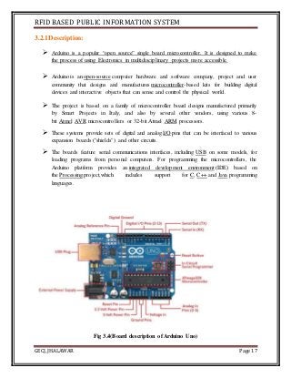
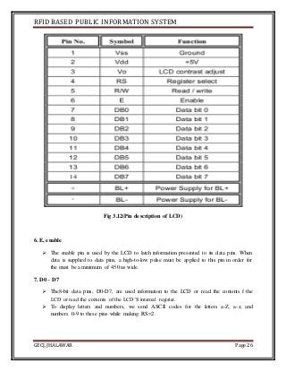
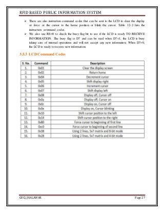
RFID BASED PUBLIC INFORMATION SYSTEM
GECJ, JHALAWAR Page 1
GOVERNMENT ENGINEERING COLLEGE, JHALAWAR
PROJECT STAGE - I
ON
“RFID BASED PUBLIC INFORMATION SYSTEM”
B.Tech.
In
ELECTRONICS & COMMUNICATION ENGINEERING
SUBMITTED BY
14EEJEC003 AlokAgrawal
14EEJEC004 AmbeshVerma
14EEJEC017 Shubham Sharma
GUIDED BY
MayankMewara Sir
Department of Electronics & Communication Engineering
Government Engineering College
Jhalawar-326001
RFID BASED PUBLIC INFORMATION SYSTEM
GECJ, JHALAWAR Page 2
GOVERNMENT ENGINEERING COLLEGE,
JHALAWAR -326001, RAJASTHAN, INDIA
CERTIFICATE
This is to certify that this project entitled RFID Based Public Information
System has been completed by AlokAgrawal, Ambesh Verma, Shubham Sharma
during VIIth semester in fulfillment of the award of the degree in Electronics
&Communication Engineering during the academic year 2017-2018.
MayankMewaraSir Mr.Nitin SuyanSir
Guide Head of Department
Ms.ChandaniBegam
Co guide
Seal of Department
RFID BASED PUBLIC INFORMATION SYSTEM
GECJ, JHALAWAR Page 3
ACKNOWLEDGEMENT
We would like to express a gratitude to everyone who gave us the every possible
guidance and help more about RFID Based Public Information Systemwhich imparted more
knowledge about the topic.
We would like to extend our gratitude to Mr.MayankMewara , Asst. Professor
Department of Electronic and Communication Engineering , Institute of Government
Engineering College,Jhalawar for fruitful discussions and valuable suggestions during meeting
and for their encouragement and motivation.
In the first instance we would like to thanks electronics & communication department of
our institute for giving us permission to commence this project . We would furthermore like to
specially thank and encouragement.
RFID BASED PUBLIC INFORMATION SYSTEM
GECJ, JHALAWAR Page 4
INDEX
TITLE PAGE
CHAPTER 1: INTRODUCTION 9
1.1 Introduction 10
1.2 RFID Background 10
1.3 Basic Of RFID 10
1.4 Working Principle 10
1.5 Aim Of Project 11
CHAPTER 2: PROPOSED METHODOLOGY 12
2.1 Block Diagram 13
2.2 Component Of Block Diagram 13
2.3Working of Block Diagram 13
CHAPTER 3: HARDWARE DESIGNING 14
3.1 Power Supply 15
3.2 Arduino Uno 16
3.3 RFID Reader 21
3.4 RFID Tag 23
3.5 LCD Display 24
 ADVANTAGES AND APPLICATION 28
Advantages 28
Application 28
 CONCLUSION 29
 REFERENCE 30
RFID BASED PUBLIC INFORMATION SYSTEM
GECJ, JHALAWAR Page 5
List of Figures Page
Fig 2.1 Block Diagram 13
Fig 3.1 Power Supply 15
Fig 3.2 Arduino Board 17
Fig 3.3 IC ATMEGA 328 17
Fig 3.4 Arduino Board Description 18
Fig 3.5 Architecture ATMEGA 328 19
Fig 3.6 Pin Diagram of ATMEGA 328 20
Fig 3.7 RFID Reader 22
Fig 3.8 Pin Description of RFID Reader 23
Fig 3.9 RFID Tags 23
Fig 3.10 Tag With Barcode And RFID 23
Fig 3.11 LCD 24
RFID BASED PUBLIC INFORMATION SYSTEM
GECJ, JHALAWAR Page 6
List of Tables Page
Table 3.3 Specification of RFID Reader 22
Table 3.4 Pin Description of RFID Reader 23
Table 3.5 Pin Description of LCD 27
Table 3.6LCD Command Codes 28
RFID BASED PUBLIC INFORMATION SYSTEM
GECJ, JHALAWAR Page 7
ABBERVATION
RFID : Radio Frequency Identification
VB : Visual Basic
PC : Personal Computer
IC : Intergrated Circuit
VCC : Voltage Control Current
GND : Ground
ADC : Analog to Digital Converter
LCD : Liquid Crystal Display
Tx : Transmitter
Rx : Receiver
AREF : Analog Reference
IDE : Integreated development Environment
RFID BASED PUBLIC INFORMATION SYSTEM
GECJ, JHALAWAR Page 8
ABSTRACT
In present days many illegal activities are talking place surrounding us RFID technology can be
effectively used to solve some of tham . As the number of people increased day by day the
process of illegal activity are increased. Security and efficiency are matter now. RFID ( Radio
Frequency Identification) emerges as one of the converging technologies. RFID plays major role
in auto id application . Here RFID technology i.e. , RFID tags are introduced , instead of aadhar
card, Voter id card , passport or any i.d. proof, which consists of all the details about the card
holder like family details, type of card and its validity etc. When a person entered with his RFID
any identity card to the any place , his tag is read by using RFID reader and displays his personal
data with photograph.
RFID BASED PUBLIC INFORMATION SYSTEM
GECJ, JHALAWAR Page 9
Chapter: 1
INTRODUCTION
RFID BASED PUBLIC INFORMATION SYSTEM
GECJ, JHALAWAR Page 10
1.1 Introduction
 Public information system is developedfor Company, college, institute, hospitals using
RFID technology.
 It facilitates the access of public information of particular students, employers in
particular company, college the information shorted by the operators.
1.2 RFID Background:
 RFID technology with the special ability of multiple object identification without the
constraint of line‐of‐sight, provides a perfect way for real‐time data collection and object
identification. Thus, an increasing number of organizations are utilizing this special
technology for business automation and management optimization.
1.3Basics Of RFID:
 RFID is a promising, emerging and advanced technology which can automatically
identify a physical object without line‐of‐sight interaction (Kwok, S. et al., 2007).
 RFID technology captures and transfers data from an item of equipment to a reader via
radio signals within a certain read range. In recent years, the applications of RFID
technology has manifested various and sophisticated trends beyond ships and airplanes
identification.
 A typical RFID system is an integrated collection of components including a tag,
antenna, reader and software. An RFID tag is attached to an item which needs to be
tracked and identified.
 The tag can transmit information concerning the object to the RFID reader via an
antenna. Then, the reader reads the information stored and forwards it over a suitable
communication channel, such as a network, to an application software running on a
computer.
1.4Working Principle
 For operating this project first user has to insert the card numbers into the ATmega 328
microcontroller memory. It can be done by college person while issuing the card.
Whenever a new student joins is enrolled in college at that time, card will be issued.
 And same entry will be made in the microcontroller program memory. In the current
project, these numbers are stored in the microcontroller’s program memory. Which
means while entering the program into memory, we need to add these card numbers into
the program. Then this card will be issued to the respective person.
 Then this project operates in normal mode. Whenever user comes near RFID reader
module and shows RFID tag then microcontroller will store information in the
RFID BASED PUBLIC INFORMATION SYSTEM
GECJ, JHALAWAR Page 11
microcontroller memory. First is the card number and second is the time at which user
has shown the card.
 Same situation happens for logout. For logging out also student will show the card. In
this project single RFID card reader module will be used for in and out operation.
1.5Aim of Project
We have choose this project of public information system because…..
 It is used for proper time management for company, college, public area.
 Ensuring the proper identification.
 It is no surprise for student to bunk college and arrive college late.
RFID BASED PUBLIC INFORMATION SYSTEM
GECJ, JHALAWAR Page 12
Chapter: 2
Proposed Methodology
RFID BASED PUBLIC INFORMATION SYSTEM
GECJ, JHALAWAR Page 13
2.1 Block Diagram
Fig 2.1(Block of attendance management system)
2.2 Component of Block Diagram
1. POWER SUPPLY
2. ARDUINO UNO
3. RFID READER
4. RFID TAG
5. LCD DISPLAY
2.3 Working of block diagram :
 Power supply: It will provide power supply to all the component connected to Arduino.
 Arduino Uno: It is the type of board which we are using in this project.
 RFID reader: Though this it is continuous getting supply it induces the magnetic field
around it, which will help it to track the tag when it enter to that magnetic field.
 RFID Tag: This card contains the identity of individual which is allotted differently to
each tag (card), with which user make his attendance.
 LCD: This will display all the details from time, name date, etc. entered by the user of
the user which tag its card.
 COMPUTER: This is used to visualize information.
RFID BASED PUBLIC INFORMATION SYSTEM
GECJ, JHALAWAR Page 14
Chapter: 3
Hardware designing
RFID BASED PUBLIC INFORMATION SYSTEM
GECJ, JHALAWAR Page 15
3.1 Power Supply
3.1.1 Description:
 The A.C. voltage, typically 220v rms, is connected to transformer, which steps that ac
voltage down the level of the desired dc output. A diode rectifier then provides the full
wave rectified voltage that is initially filtered by a simple capacitor filter to produce a dc
voltage .This resulting dc voltage usually has some ripple on ac voltage variation.
 A regulator circuit removes the ripples and also remains the same dc value even if the
input dc voltage varies,or the load connected to the output dc voltage changes. This
voltage regulation is usually obtained using one of the popular voltage regulators IC
units.
Fig 3.1(Power supply)
Transformer:
 The potential transformer will step down the power supply voltage (0-230v) to (0-6v)
level. Then the secondary of the potential transformer will be connected to the precision
rectifier, which is constructed with the help of op-amp. The advantages of using precision
rectifier are- it will give peak voltage output as DC, rest of the circuits will give only
RMS output.
Bridge Rectifier:
 When four diodes are connected as shown in figure, the circuit is called as bridge
rectifier. The input of the circuit is applied to the diagonally opposite corner of the
network and the output is taken from the remaining . Let us assume that the transformer
is working properly and there is a positive potential at point A and negative potential
point B.The positive potential at point A will be forward bias D3 and reverse bias D4.
RFID BASED PUBLIC INFORMATION SYSTEM
GECJ, JHALAWAR Page 16
 Negative potential at point B then forward bias D1and reverse bias at D2.At this time D3
& D1 are forward bias and will allow current flow to pass through them; D4 &D2 are
reverse bias and will block current flow.
 The path for current flow from point B through D1, up through RL, through D3, through
the secondary of the transformer back to point B this path is indicated by the solid
arrows.
IC 7805(Voltage regulator):
 The LM 7805 series of the three terminal regulations is available with several fixed
output voltages making them useful in a wide range of applications.
 One of these is local on card regulation. The voltages available allow these regulators to
be used in logic systems, instrumentation and other solid state electronic equipment.
Although designed primarily as fixed voltage regulators, these devices can be used with
external components to obtain adjustable voltages and currents.
 The LM 7805 is available in aluminum to 3 packages which will allow over 1.5a load
current if adequate heat sinking is provided. Current limiting is included to limit the peak
output current to a safe value.
 The LM 7805 is available in the metal 3 leads to 5 and the plastic to 92.The regulator can
deliver 100mA output current. The advantage of this type of regulator is, it is easy to use
and minimize the number of external components.
3.1.2 Features of Power Supply
 Output current in excess of 1.5A for 78 and 78L series
 Internal thermal overload protection
 No external components required
 Output transistor sage area protection
 Internal short circuit current limit.
3.2 Arduino Uno
Fig3.2 (Arduino board)Fig3.3(IC ATmega328)
RFID BASED PUBLIC INFORMATION SYSTEM
GECJ, JHALAWAR Page 17
3.2.1Description:
 Arduino is a popular “open source” single board microcontroller. It is designed to make
the process of using Electronics in multidisciplinary projects more accessible.
 Arduino is an open-source computer hardware and software company, project and user
community that designs and manufactures microcontroller-based kits for building digital
devices and interactive objects that can sense and control the physical world.
 The project is based on a family of microcontroller board designs manufactured primarily
by Smart Projects in Italy, and also by several other vendors, using various 8-
bit Atmel AVR microcontrollers or 32-bit Atmel ARM processors.
 These systems provide sets of digital and analog I/O pins that can be interfaced to various
expansion boards ("shields") and other circuits.
 The boards feature serial communications interfaces, including USB on some models, for
loading programs from personal computers. For programming the microcontrollers, the
Arduino platform provides an integrated development environment (IDE) based on
the Processing project,which includes support for C, C++ and Java programming
languages.
Fig 3.4(Board description of Arduino Uno)
RFID BASED PUBLIC INFORMATION SYSTEM
GECJ, JHALAWAR Page 18
3.2.2 Block Diagram:
Fig 3.5(Architecture of ATmega328)
RFID BASED PUBLIC INFORMATION SYSTEM
GECJ, JHALAWAR Page 19
3.2.3 Pin Description:
Fig 3.6
(Pin description of ATmega328)
1.VCC:
 Digital supply voltage.
2. GND:
 Ground
3. Port B (PB7:0):
 Port B is an 8-bit bi-directional I/O port with internal pull-up resistors (selected for each
bit). The Port B output.
 Buffers have symmetrical drive characteristics with both high sink and source capability.
As inputs, Port B pins that are externally pulled low will source current if the pull-up
resistors are activated. The Port B pins are tristatedwhen a reset condition becomes
active, even if the clock is not running.
 Depending on the clock selection fuse settings, PB6 can be used as input to the inverting
Oscillator amplifierand input to the internal clock operating circuit.
RFID BASED PUBLIC INFORMATION SYSTEM
GECJ, JHALAWAR Page 20
 Depending on the clock selection fuse settings, PB7 can be used as output from the
inverting Oscillatoramplifier.
4.Port C (PC5:0):
 Port C is a 7-bit bi-directional I/O port with internal pull-up resistors (selected for each
bit). The PC5...0 outputbuffers have symmetrical drive characteristics with both high sink
and source capability. As inputs, Port C pinsthat are externally pulled low will source
current if the pull-up resistors are activated. The Port C pins are tristatedwhen a reset
condition becomes active, even if the clock is not running.
5. PC6/RESET:
 If the RSTDISBL Fuse is programmed, PC6 is used as an I/O pin. Note that the electrical
characteristics of PC6differ from those of the other pins of Port C.
 If the RSTDISBL Fuse is unprogrammed, PC6 is used as a Reset input. A low level on
this pin for longer thanthe minimum pulse length will generate a Reset, even if the clock
is not running. The minimum pulse length isShorter pulses are not guaranteed to generate
a Reset.
6.Port D (PD7:0):
 Port D is an 8-bit bi-directional I/O port with internal pull-up resistors (selected for each
bit). The Port D output buffers have symmetrical drive characteristics with both high sink
and source capability. As inputs, Port D pinsthat are externally pulled low will source
current if the pull-up resistors are activated. The Port D pins are tristatedwhen a reset
condition becomes active, even if the clock is not running.
7. AVCC:
 AVCC is the supply voltage pin for the A/D Converter, PC3:0. It should be externally
connected toVCC, even if the ADC is not used. If the ADC is used, it should be
connected to VCC through a low-pass filter.
8. AREF:
 AREF is the analog reference pin for the A/D Converter.
3.2.4 Features ofArduino Uno
 High Performance, Low Power Atmel 8-Bit Microcontroller Family
 Advanced RISC Architecture
 131 Powerful Instructions – Most Single Clock Cycle Execution
 32 x 8 General Purpose Working Registers
 Fully Static Operation
RFID BASED PUBLIC INFORMATION SYSTEM
GECJ, JHALAWAR Page 21
 High Endurance Non-volatile Memory Segments
 Special Microcontroller Features
 Power-on Reset and Programmable Brown-out Detection
 Internal Calibrated Oscillator
 External and Internal Interrupt Sources
 Six Sleep Modes: Idle, ADC Noise Reduction, Power-save, Power-down,
Standby, and Extended Standby
 I/O and Packages
 23 Programmable I/O Lines
 Operating Voltage:1.8 - 5.5V
 Temperature Range:400C to 850C
 Power Consumption at 1MHz, 1.8V, 250c
 Active Mode: 0.2mA
 Power-down Mode: 0.1μA
 Power-save Mode: 0.75μA
3.3 RFID Reader
Fig 3.7(RFID Reader module)
3.3.1 Description:
 This is great little RFID reader module from innovation. If u needs an in expensive way
to get started with this is great module. Just power the module, and it will read any RFID
card within range.
 It will output the card id in serial string ,which can easily we read by any microcontroller
the spacing on pin is 2.55mm which means the module will directly feet on breadboard.
 A reader contains an RF module, which acts as both a transmitter and receiver of radio
frequency signals. The transmitter consists of an oscillator to create the carrier frequency;
RFID BASED PUBLIC INFORMATION SYSTEM
GECJ, JHALAWAR Page 22
a modulator to overwrite data commands upon this carrier signal and an amplifier to
boost the signal enough to awaken the tag.
 The receiver has a demodulator to extract the returned data and also contains an amplifier
to strengthen the signal for processing. A microprocessor forms the control unit, which
employs an operating system and memory to filter and store the data. The data is now
ready to store.
3.3.2 Features of RFID Reader
 +5v supply
 125KHz read frequency
 EM4001 64-BIT RFID TAD COMPATIBLE
 9600BPS TTL and RS232 output
 Magnetic stripe emulation output
 100mm read range
3.3.3Specification
Power source +5v
Electric current <60mA
Frequency 125KHz
Reads the card distance >5cm
Output Wigand 26 DATA 0,Wiegand 26 DATA 1 RS 232
Size 25*16*13mm
3.3.4 Pin Descriptionof RFID Reader
Fig 3.8(Pin description of RFID Reader)
RFID BASED PUBLIC INFORMATION SYSTEM
GECJ, JHALAWAR Page 23
PIN NO. PIN DESCRIPTION
1. VCC Supply +5 v
2.GND Supply GND
3.BEEP Buzzer
4.N/A --
5.N/A --
6.SEL Mode selection pin(1 : Uart TX, 0 :
Weigand Output)
7.RS232 Transmission
8.D1 Weigand data 1
9.D0 Weigand data 0
3.4 RFID Tag
Fig 3.9 Fig 3.10
(RFID Tag) (Tag with barcode and RFID)
3.4.1 Description:
 Radio-frequency identification (RFID) is a technology to record the presence of an object
using radio signals. RFID is not a replacement for the bar coding, but a complement for
distant reading of codes.
 The technology is used for automatically identifying a package or an item. To do this, it
applicable on RFID tags.
 These are small transponders (combined radio receiver and transmitter) that will transmit
identity information over a short distance, when asked. The other piece to make use of
RFID tags is an RFID tag reader.
 Most tags carry a plain text inscription and a barcode as complements for direct reading
and for cases of any failure of radio frequency electronics.
RFID BASED PUBLIC INFORMATION SYSTEM
GECJ, JHALAWAR Page 24
 Most RFID tags contain at least two parts. One is an integrated circuit for storing and
processing information, modulating and de-modulating a radio-frequency (RF) signal,
and other specialized functions. The second is an antenna for receiving and transmitting
the signal.
 There are generally two types of RFID tags: active RFID tags
 A passive tag is an RFID tag that does not contain a battery; the power is supplied by the
reader. When radio waves from the reader are encountered by a passive rfid tag, the
coiled antenna within the tag forms a magnetic field. The tag draws power from it,
energizing the circuits in the tag. The tag then sends the information encoded in the tag's
memory.
3.4.2 Advantages of a passive tag:
 The tag functions without a battery; these tags have a useful life of twenty years or more.
 The tag is typically much less expensive to manufacture
 The tag is much smaller (some tags are the size of a grain of rice). These tags have almost
unlimited applications in consumer goods and other areas.
3.4.3 Disadvantages of a passive RFID tag:
 The tag can be read only at very short distances, typically a few feet at most. This greatly
limits the device for certain applications.
 It may not be possible to include sensors that can use electricity for power.
 The tag remains readable for a very long time, even after the product to which the tag is
attached has been sold and is no longer being tracked.
3.5 LCD Display
3.5.1 Description:
Fig 3.11(16x2 LCD)
RFID BASED PUBLIC INFORMATION SYSTEM
GECJ, JHALAWAR Page 25
 LCD (Liquid Crystal Display) screen is an electronic display module and find a wide
range of applications. A 16x2 LCD display is very basic module and is very commonly
used in various devices and circuits.
 These modules are preferred over seven segments and other multi segment LEDs. The
reasons being: LCDs are economical; easily programmable; have no limitation of
displaying special & even custom characters (unlike in seven segments), animations and
so on.
 A 16x2 LCD means it can display 16 characters per line and there are 2 such lines. In this
LCD each character is displayed in 5x7 pixel matrix. This LCD has two registers,
namely, Command and Data.
 The command register stores the command instructions given to the LCD. A command is
an instruction given to LCD to do a predefined task like initializing it, clearing its screen,
setting the cursor position, controlling display etc.
 The data register stores the data to be displayed on the LCD. The data is the ASCII value
of the character to be displayed on the LCD. Click to learn more about internal structure
of a LCD.
3.5.2PinDescriptionof LCD
1.VCC:
 Digital +5v supply voltage.
2. VSS:
 Ground.
3. VEE:
 Power supply to control contrast.
4. RS, register select
 There are two very important registers inside the LCD. The RS pin is used for their
selection as follows. If RS=0, the instruction command code register is selected, allowing
the user to send a command such as clear display, cursor at home etc. If RS=1 the date
register is selected, allowing the user to send data to be displayed on the LCD.
5. r/w, read/write
 R/W input allows the user to write information to the LCD or read information from
It.R/W =1 when reading; R/W =0 when writing.
RFID BASED PUBLIC INFORMATION SYSTEM
GECJ, JHALAWAR Page 26
Fig 3.12(Pin description of LCD)
6. E, enable
 The enable pin is used by the LCD to latch information presented to its data pins. When
data is supplied to data pins, a high-to-low pulse must be applied to this pin in order for
the must be a minimum of 450 ns wide.
7. D0 – D7
 The8-bit data pins, D0-D7, are used information to the LCD or read the contents f the
LCD or read the contents of the LCD’S internal register.
 To display letters and numbers, we send ASCII codes for the letters a-Z, a-z, and
numbers 0-9 to these pins while making RS=2.
RFID BASED PUBLIC INFORMATION SYSTEM
GECJ, JHALAWAR Page 27
 There are also instruction command codes that can be sent to the LCD to clear the display
or force or the cursor to the home position or blink the cursor. Table 12-2 lists the
instruction command codes.
 We also use RS=0 to check the busy flag bit to see if the LCD is ready TO RECEIVE
INFORMATION. The busy flag is D7 and can be read when D7=1, the LCD is busy
taking care of internal operations and will not accept any new information. When D7=0,
the LCD is ready to receive new information.
3.5.3 LCD Command Codes
RFID BASED PUBLIC INFORMATION SYSTEM
GECJ, JHALAWAR Page 28
4.1ADVANTAGE
 Small in size
 Easy to operate
 To reduce operation cost
 Records are kept safe and confidential
 All records are available in instant
 Need less manpower
4.2APPLICATIONS
 Software companies and production industries
 In colleges and varies educational institutes as well as university campus.
 It can be used in shops, shopping malls for the employees.
RFID BASED PUBLIC INFORMATION SYSTEM
GECJ, JHALAWAR Page 29
CONCLUSION
The RFID technology is an innovation solution to the current use of fake
identification. It is tool for passport office ,votor id office , pan card office school, likes such
places to security purpose for more accuracy in our identification documentation . RFID has the
characterstics different from the currently used barcode labels. In recent time many places are
use the RFID technology but most people’s are aware this technology.
According above chapters described we have designed RFID based public information
system for desktop application to provide user interface with database which includes
information of the user. It is use for security such places like Government places hospitals etc. Its
development will be dependent on the factors of applicant use. The RFID based public
information system is develop for stop the illegal activities.
RFID BASED PUBLIC INFORMATION SYSTEM
GECJ, JHALAWAR Page 30
REFERENCE
 The 8051 microcontroller and embedded systems by Janice gillispiemazidi.
Websites
 http://www.technovely.com
 www.engineeringsgarage.com
 www.ijert.org
 www.edgefxkits.com
 www.instructables.com
 www.elprocus.com
 www.seminarproject.org
Datasheets:
 LM7805 datasheet(http://www.ti.com/LM7805)
 DS1307datasheet(www.datasheets.maximintegrated.com/en/ds/DS1307.pdf)
 EM-18 datasheet(http://forum.researchdesignlab.com/datasheet/EM18)
 ATmega 328 datasheet(http://www.atmel.com)

Rfid report

  • 1.
    RFID BASED PUBLICINFORMATION SYSTEM GECJ, JHALAWAR Page 1 GOVERNMENT ENGINEERING COLLEGE, JHALAWAR PROJECT STAGE - I ON “RFID BASED PUBLIC INFORMATION SYSTEM” B.Tech. In ELECTRONICS & COMMUNICATION ENGINEERING SUBMITTED BY 14EEJEC003 AlokAgrawal 14EEJEC004 AmbeshVerma 14EEJEC017 Shubham Sharma GUIDED BY MayankMewara Sir Department of Electronics & Communication Engineering Government Engineering College Jhalawar-326001
  • 2.
    RFID BASED PUBLICINFORMATION SYSTEM GECJ, JHALAWAR Page 2 GOVERNMENT ENGINEERING COLLEGE, JHALAWAR -326001, RAJASTHAN, INDIA CERTIFICATE This is to certify that this project entitled RFID Based Public Information System has been completed by AlokAgrawal, Ambesh Verma, Shubham Sharma during VIIth semester in fulfillment of the award of the degree in Electronics &Communication Engineering during the academic year 2017-2018. MayankMewaraSir Mr.Nitin SuyanSir Guide Head of Department Ms.ChandaniBegam Co guide Seal of Department
  • 3.
    RFID BASED PUBLICINFORMATION SYSTEM GECJ, JHALAWAR Page 3 ACKNOWLEDGEMENT We would like to express a gratitude to everyone who gave us the every possible guidance and help more about RFID Based Public Information Systemwhich imparted more knowledge about the topic. We would like to extend our gratitude to Mr.MayankMewara , Asst. Professor Department of Electronic and Communication Engineering , Institute of Government Engineering College,Jhalawar for fruitful discussions and valuable suggestions during meeting and for their encouragement and motivation. In the first instance we would like to thanks electronics & communication department of our institute for giving us permission to commence this project . We would furthermore like to specially thank and encouragement.
  • 4.
    RFID BASED PUBLICINFORMATION SYSTEM GECJ, JHALAWAR Page 4 INDEX TITLE PAGE CHAPTER 1: INTRODUCTION 9 1.1 Introduction 10 1.2 RFID Background 10 1.3 Basic Of RFID 10 1.4 Working Principle 10 1.5 Aim Of Project 11 CHAPTER 2: PROPOSED METHODOLOGY 12 2.1 Block Diagram 13 2.2 Component Of Block Diagram 13 2.3Working of Block Diagram 13 CHAPTER 3: HARDWARE DESIGNING 14 3.1 Power Supply 15 3.2 Arduino Uno 16 3.3 RFID Reader 21 3.4 RFID Tag 23 3.5 LCD Display 24  ADVANTAGES AND APPLICATION 28 Advantages 28 Application 28  CONCLUSION 29  REFERENCE 30
  • 5.
    RFID BASED PUBLICINFORMATION SYSTEM GECJ, JHALAWAR Page 5 List of Figures Page Fig 2.1 Block Diagram 13 Fig 3.1 Power Supply 15 Fig 3.2 Arduino Board 17 Fig 3.3 IC ATMEGA 328 17 Fig 3.4 Arduino Board Description 18 Fig 3.5 Architecture ATMEGA 328 19 Fig 3.6 Pin Diagram of ATMEGA 328 20 Fig 3.7 RFID Reader 22 Fig 3.8 Pin Description of RFID Reader 23 Fig 3.9 RFID Tags 23 Fig 3.10 Tag With Barcode And RFID 23 Fig 3.11 LCD 24
  • 6.
    RFID BASED PUBLICINFORMATION SYSTEM GECJ, JHALAWAR Page 6 List of Tables Page Table 3.3 Specification of RFID Reader 22 Table 3.4 Pin Description of RFID Reader 23 Table 3.5 Pin Description of LCD 27 Table 3.6LCD Command Codes 28
  • 7.
    RFID BASED PUBLICINFORMATION SYSTEM GECJ, JHALAWAR Page 7 ABBERVATION RFID : Radio Frequency Identification VB : Visual Basic PC : Personal Computer IC : Intergrated Circuit VCC : Voltage Control Current GND : Ground ADC : Analog to Digital Converter LCD : Liquid Crystal Display Tx : Transmitter Rx : Receiver AREF : Analog Reference IDE : Integreated development Environment
  • 8.
    RFID BASED PUBLICINFORMATION SYSTEM GECJ, JHALAWAR Page 8 ABSTRACT In present days many illegal activities are talking place surrounding us RFID technology can be effectively used to solve some of tham . As the number of people increased day by day the process of illegal activity are increased. Security and efficiency are matter now. RFID ( Radio Frequency Identification) emerges as one of the converging technologies. RFID plays major role in auto id application . Here RFID technology i.e. , RFID tags are introduced , instead of aadhar card, Voter id card , passport or any i.d. proof, which consists of all the details about the card holder like family details, type of card and its validity etc. When a person entered with his RFID any identity card to the any place , his tag is read by using RFID reader and displays his personal data with photograph.
  • 9.
    RFID BASED PUBLICINFORMATION SYSTEM GECJ, JHALAWAR Page 9 Chapter: 1 INTRODUCTION
  • 10.
    RFID BASED PUBLICINFORMATION SYSTEM GECJ, JHALAWAR Page 10 1.1 Introduction  Public information system is developedfor Company, college, institute, hospitals using RFID technology.  It facilitates the access of public information of particular students, employers in particular company, college the information shorted by the operators. 1.2 RFID Background:  RFID technology with the special ability of multiple object identification without the constraint of line‐of‐sight, provides a perfect way for real‐time data collection and object identification. Thus, an increasing number of organizations are utilizing this special technology for business automation and management optimization. 1.3Basics Of RFID:  RFID is a promising, emerging and advanced technology which can automatically identify a physical object without line‐of‐sight interaction (Kwok, S. et al., 2007).  RFID technology captures and transfers data from an item of equipment to a reader via radio signals within a certain read range. In recent years, the applications of RFID technology has manifested various and sophisticated trends beyond ships and airplanes identification.  A typical RFID system is an integrated collection of components including a tag, antenna, reader and software. An RFID tag is attached to an item which needs to be tracked and identified.  The tag can transmit information concerning the object to the RFID reader via an antenna. Then, the reader reads the information stored and forwards it over a suitable communication channel, such as a network, to an application software running on a computer. 1.4Working Principle  For operating this project first user has to insert the card numbers into the ATmega 328 microcontroller memory. It can be done by college person while issuing the card. Whenever a new student joins is enrolled in college at that time, card will be issued.  And same entry will be made in the microcontroller program memory. In the current project, these numbers are stored in the microcontroller’s program memory. Which means while entering the program into memory, we need to add these card numbers into the program. Then this card will be issued to the respective person.  Then this project operates in normal mode. Whenever user comes near RFID reader module and shows RFID tag then microcontroller will store information in the
  • 11.
    RFID BASED PUBLICINFORMATION SYSTEM GECJ, JHALAWAR Page 11 microcontroller memory. First is the card number and second is the time at which user has shown the card.  Same situation happens for logout. For logging out also student will show the card. In this project single RFID card reader module will be used for in and out operation. 1.5Aim of Project We have choose this project of public information system because…..  It is used for proper time management for company, college, public area.  Ensuring the proper identification.  It is no surprise for student to bunk college and arrive college late.
  • 12.
    RFID BASED PUBLICINFORMATION SYSTEM GECJ, JHALAWAR Page 12 Chapter: 2 Proposed Methodology
  • 13.
    RFID BASED PUBLICINFORMATION SYSTEM GECJ, JHALAWAR Page 13 2.1 Block Diagram Fig 2.1(Block of attendance management system) 2.2 Component of Block Diagram 1. POWER SUPPLY 2. ARDUINO UNO 3. RFID READER 4. RFID TAG 5. LCD DISPLAY 2.3 Working of block diagram :  Power supply: It will provide power supply to all the component connected to Arduino.  Arduino Uno: It is the type of board which we are using in this project.  RFID reader: Though this it is continuous getting supply it induces the magnetic field around it, which will help it to track the tag when it enter to that magnetic field.  RFID Tag: This card contains the identity of individual which is allotted differently to each tag (card), with which user make his attendance.  LCD: This will display all the details from time, name date, etc. entered by the user of the user which tag its card.  COMPUTER: This is used to visualize information.
  • 14.
    RFID BASED PUBLICINFORMATION SYSTEM GECJ, JHALAWAR Page 14 Chapter: 3 Hardware designing
  • 15.
    RFID BASED PUBLICINFORMATION SYSTEM GECJ, JHALAWAR Page 15 3.1 Power Supply 3.1.1 Description:  The A.C. voltage, typically 220v rms, is connected to transformer, which steps that ac voltage down the level of the desired dc output. A diode rectifier then provides the full wave rectified voltage that is initially filtered by a simple capacitor filter to produce a dc voltage .This resulting dc voltage usually has some ripple on ac voltage variation.  A regulator circuit removes the ripples and also remains the same dc value even if the input dc voltage varies,or the load connected to the output dc voltage changes. This voltage regulation is usually obtained using one of the popular voltage regulators IC units. Fig 3.1(Power supply) Transformer:  The potential transformer will step down the power supply voltage (0-230v) to (0-6v) level. Then the secondary of the potential transformer will be connected to the precision rectifier, which is constructed with the help of op-amp. The advantages of using precision rectifier are- it will give peak voltage output as DC, rest of the circuits will give only RMS output. Bridge Rectifier:  When four diodes are connected as shown in figure, the circuit is called as bridge rectifier. The input of the circuit is applied to the diagonally opposite corner of the network and the output is taken from the remaining . Let us assume that the transformer is working properly and there is a positive potential at point A and negative potential point B.The positive potential at point A will be forward bias D3 and reverse bias D4.
  • 16.
    RFID BASED PUBLICINFORMATION SYSTEM GECJ, JHALAWAR Page 16  Negative potential at point B then forward bias D1and reverse bias at D2.At this time D3 & D1 are forward bias and will allow current flow to pass through them; D4 &D2 are reverse bias and will block current flow.  The path for current flow from point B through D1, up through RL, through D3, through the secondary of the transformer back to point B this path is indicated by the solid arrows. IC 7805(Voltage regulator):  The LM 7805 series of the three terminal regulations is available with several fixed output voltages making them useful in a wide range of applications.  One of these is local on card regulation. The voltages available allow these regulators to be used in logic systems, instrumentation and other solid state electronic equipment. Although designed primarily as fixed voltage regulators, these devices can be used with external components to obtain adjustable voltages and currents.  The LM 7805 is available in aluminum to 3 packages which will allow over 1.5a load current if adequate heat sinking is provided. Current limiting is included to limit the peak output current to a safe value.  The LM 7805 is available in the metal 3 leads to 5 and the plastic to 92.The regulator can deliver 100mA output current. The advantage of this type of regulator is, it is easy to use and minimize the number of external components. 3.1.2 Features of Power Supply  Output current in excess of 1.5A for 78 and 78L series  Internal thermal overload protection  No external components required  Output transistor sage area protection  Internal short circuit current limit. 3.2 Arduino Uno Fig3.2 (Arduino board)Fig3.3(IC ATmega328)
  • 17.
    RFID BASED PUBLICINFORMATION SYSTEM GECJ, JHALAWAR Page 17 3.2.1Description:  Arduino is a popular “open source” single board microcontroller. It is designed to make the process of using Electronics in multidisciplinary projects more accessible.  Arduino is an open-source computer hardware and software company, project and user community that designs and manufactures microcontroller-based kits for building digital devices and interactive objects that can sense and control the physical world.  The project is based on a family of microcontroller board designs manufactured primarily by Smart Projects in Italy, and also by several other vendors, using various 8- bit Atmel AVR microcontrollers or 32-bit Atmel ARM processors.  These systems provide sets of digital and analog I/O pins that can be interfaced to various expansion boards ("shields") and other circuits.  The boards feature serial communications interfaces, including USB on some models, for loading programs from personal computers. For programming the microcontrollers, the Arduino platform provides an integrated development environment (IDE) based on the Processing project,which includes support for C, C++ and Java programming languages. Fig 3.4(Board description of Arduino Uno)
  • 18.
    RFID BASED PUBLICINFORMATION SYSTEM GECJ, JHALAWAR Page 18 3.2.2 Block Diagram: Fig 3.5(Architecture of ATmega328)
  • 19.
    RFID BASED PUBLICINFORMATION SYSTEM GECJ, JHALAWAR Page 19 3.2.3 Pin Description: Fig 3.6 (Pin description of ATmega328) 1.VCC:  Digital supply voltage. 2. GND:  Ground 3. Port B (PB7:0):  Port B is an 8-bit bi-directional I/O port with internal pull-up resistors (selected for each bit). The Port B output.  Buffers have symmetrical drive characteristics with both high sink and source capability. As inputs, Port B pins that are externally pulled low will source current if the pull-up resistors are activated. The Port B pins are tristatedwhen a reset condition becomes active, even if the clock is not running.  Depending on the clock selection fuse settings, PB6 can be used as input to the inverting Oscillator amplifierand input to the internal clock operating circuit.
  • 20.
    RFID BASED PUBLICINFORMATION SYSTEM GECJ, JHALAWAR Page 20  Depending on the clock selection fuse settings, PB7 can be used as output from the inverting Oscillatoramplifier. 4.Port C (PC5:0):  Port C is a 7-bit bi-directional I/O port with internal pull-up resistors (selected for each bit). The PC5...0 outputbuffers have symmetrical drive characteristics with both high sink and source capability. As inputs, Port C pinsthat are externally pulled low will source current if the pull-up resistors are activated. The Port C pins are tristatedwhen a reset condition becomes active, even if the clock is not running. 5. PC6/RESET:  If the RSTDISBL Fuse is programmed, PC6 is used as an I/O pin. Note that the electrical characteristics of PC6differ from those of the other pins of Port C.  If the RSTDISBL Fuse is unprogrammed, PC6 is used as a Reset input. A low level on this pin for longer thanthe minimum pulse length will generate a Reset, even if the clock is not running. The minimum pulse length isShorter pulses are not guaranteed to generate a Reset. 6.Port D (PD7:0):  Port D is an 8-bit bi-directional I/O port with internal pull-up resistors (selected for each bit). The Port D output buffers have symmetrical drive characteristics with both high sink and source capability. As inputs, Port D pinsthat are externally pulled low will source current if the pull-up resistors are activated. The Port D pins are tristatedwhen a reset condition becomes active, even if the clock is not running. 7. AVCC:  AVCC is the supply voltage pin for the A/D Converter, PC3:0. It should be externally connected toVCC, even if the ADC is not used. If the ADC is used, it should be connected to VCC through a low-pass filter. 8. AREF:  AREF is the analog reference pin for the A/D Converter. 3.2.4 Features ofArduino Uno  High Performance, Low Power Atmel 8-Bit Microcontroller Family  Advanced RISC Architecture  131 Powerful Instructions – Most Single Clock Cycle Execution  32 x 8 General Purpose Working Registers  Fully Static Operation
  • 21.
    RFID BASED PUBLICINFORMATION SYSTEM GECJ, JHALAWAR Page 21  High Endurance Non-volatile Memory Segments  Special Microcontroller Features  Power-on Reset and Programmable Brown-out Detection  Internal Calibrated Oscillator  External and Internal Interrupt Sources  Six Sleep Modes: Idle, ADC Noise Reduction, Power-save, Power-down, Standby, and Extended Standby  I/O and Packages  23 Programmable I/O Lines  Operating Voltage:1.8 - 5.5V  Temperature Range:400C to 850C  Power Consumption at 1MHz, 1.8V, 250c  Active Mode: 0.2mA  Power-down Mode: 0.1μA  Power-save Mode: 0.75μA 3.3 RFID Reader Fig 3.7(RFID Reader module) 3.3.1 Description:  This is great little RFID reader module from innovation. If u needs an in expensive way to get started with this is great module. Just power the module, and it will read any RFID card within range.  It will output the card id in serial string ,which can easily we read by any microcontroller the spacing on pin is 2.55mm which means the module will directly feet on breadboard.  A reader contains an RF module, which acts as both a transmitter and receiver of radio frequency signals. The transmitter consists of an oscillator to create the carrier frequency;
  • 22.
    RFID BASED PUBLICINFORMATION SYSTEM GECJ, JHALAWAR Page 22 a modulator to overwrite data commands upon this carrier signal and an amplifier to boost the signal enough to awaken the tag.  The receiver has a demodulator to extract the returned data and also contains an amplifier to strengthen the signal for processing. A microprocessor forms the control unit, which employs an operating system and memory to filter and store the data. The data is now ready to store. 3.3.2 Features of RFID Reader  +5v supply  125KHz read frequency  EM4001 64-BIT RFID TAD COMPATIBLE  9600BPS TTL and RS232 output  Magnetic stripe emulation output  100mm read range 3.3.3Specification Power source +5v Electric current <60mA Frequency 125KHz Reads the card distance >5cm Output Wigand 26 DATA 0,Wiegand 26 DATA 1 RS 232 Size 25*16*13mm 3.3.4 Pin Descriptionof RFID Reader Fig 3.8(Pin description of RFID Reader)
  • 23.
    RFID BASED PUBLICINFORMATION SYSTEM GECJ, JHALAWAR Page 23 PIN NO. PIN DESCRIPTION 1. VCC Supply +5 v 2.GND Supply GND 3.BEEP Buzzer 4.N/A -- 5.N/A -- 6.SEL Mode selection pin(1 : Uart TX, 0 : Weigand Output) 7.RS232 Transmission 8.D1 Weigand data 1 9.D0 Weigand data 0 3.4 RFID Tag Fig 3.9 Fig 3.10 (RFID Tag) (Tag with barcode and RFID) 3.4.1 Description:  Radio-frequency identification (RFID) is a technology to record the presence of an object using radio signals. RFID is not a replacement for the bar coding, but a complement for distant reading of codes.  The technology is used for automatically identifying a package or an item. To do this, it applicable on RFID tags.  These are small transponders (combined radio receiver and transmitter) that will transmit identity information over a short distance, when asked. The other piece to make use of RFID tags is an RFID tag reader.  Most tags carry a plain text inscription and a barcode as complements for direct reading and for cases of any failure of radio frequency electronics.
  • 24.
    RFID BASED PUBLICINFORMATION SYSTEM GECJ, JHALAWAR Page 24  Most RFID tags contain at least two parts. One is an integrated circuit for storing and processing information, modulating and de-modulating a radio-frequency (RF) signal, and other specialized functions. The second is an antenna for receiving and transmitting the signal.  There are generally two types of RFID tags: active RFID tags  A passive tag is an RFID tag that does not contain a battery; the power is supplied by the reader. When radio waves from the reader are encountered by a passive rfid tag, the coiled antenna within the tag forms a magnetic field. The tag draws power from it, energizing the circuits in the tag. The tag then sends the information encoded in the tag's memory. 3.4.2 Advantages of a passive tag:  The tag functions without a battery; these tags have a useful life of twenty years or more.  The tag is typically much less expensive to manufacture  The tag is much smaller (some tags are the size of a grain of rice). These tags have almost unlimited applications in consumer goods and other areas. 3.4.3 Disadvantages of a passive RFID tag:  The tag can be read only at very short distances, typically a few feet at most. This greatly limits the device for certain applications.  It may not be possible to include sensors that can use electricity for power.  The tag remains readable for a very long time, even after the product to which the tag is attached has been sold and is no longer being tracked. 3.5 LCD Display 3.5.1 Description: Fig 3.11(16x2 LCD)
  • 25.
    RFID BASED PUBLICINFORMATION SYSTEM GECJ, JHALAWAR Page 25  LCD (Liquid Crystal Display) screen is an electronic display module and find a wide range of applications. A 16x2 LCD display is very basic module and is very commonly used in various devices and circuits.  These modules are preferred over seven segments and other multi segment LEDs. The reasons being: LCDs are economical; easily programmable; have no limitation of displaying special & even custom characters (unlike in seven segments), animations and so on.  A 16x2 LCD means it can display 16 characters per line and there are 2 such lines. In this LCD each character is displayed in 5x7 pixel matrix. This LCD has two registers, namely, Command and Data.  The command register stores the command instructions given to the LCD. A command is an instruction given to LCD to do a predefined task like initializing it, clearing its screen, setting the cursor position, controlling display etc.  The data register stores the data to be displayed on the LCD. The data is the ASCII value of the character to be displayed on the LCD. Click to learn more about internal structure of a LCD. 3.5.2PinDescriptionof LCD 1.VCC:  Digital +5v supply voltage. 2. VSS:  Ground. 3. VEE:  Power supply to control contrast. 4. RS, register select  There are two very important registers inside the LCD. The RS pin is used for their selection as follows. If RS=0, the instruction command code register is selected, allowing the user to send a command such as clear display, cursor at home etc. If RS=1 the date register is selected, allowing the user to send data to be displayed on the LCD. 5. r/w, read/write  R/W input allows the user to write information to the LCD or read information from It.R/W =1 when reading; R/W =0 when writing.
  • 26.
    RFID BASED PUBLICINFORMATION SYSTEM GECJ, JHALAWAR Page 26 Fig 3.12(Pin description of LCD) 6. E, enable  The enable pin is used by the LCD to latch information presented to its data pins. When data is supplied to data pins, a high-to-low pulse must be applied to this pin in order for the must be a minimum of 450 ns wide. 7. D0 – D7  The8-bit data pins, D0-D7, are used information to the LCD or read the contents f the LCD or read the contents of the LCD’S internal register.  To display letters and numbers, we send ASCII codes for the letters a-Z, a-z, and numbers 0-9 to these pins while making RS=2.
  • 27.
    RFID BASED PUBLICINFORMATION SYSTEM GECJ, JHALAWAR Page 27  There are also instruction command codes that can be sent to the LCD to clear the display or force or the cursor to the home position or blink the cursor. Table 12-2 lists the instruction command codes.  We also use RS=0 to check the busy flag bit to see if the LCD is ready TO RECEIVE INFORMATION. The busy flag is D7 and can be read when D7=1, the LCD is busy taking care of internal operations and will not accept any new information. When D7=0, the LCD is ready to receive new information. 3.5.3 LCD Command Codes
  • 28.
    RFID BASED PUBLICINFORMATION SYSTEM GECJ, JHALAWAR Page 28 4.1ADVANTAGE  Small in size  Easy to operate  To reduce operation cost  Records are kept safe and confidential  All records are available in instant  Need less manpower 4.2APPLICATIONS  Software companies and production industries  In colleges and varies educational institutes as well as university campus.  It can be used in shops, shopping malls for the employees.
  • 29.
    RFID BASED PUBLICINFORMATION SYSTEM GECJ, JHALAWAR Page 29 CONCLUSION The RFID technology is an innovation solution to the current use of fake identification. It is tool for passport office ,votor id office , pan card office school, likes such places to security purpose for more accuracy in our identification documentation . RFID has the characterstics different from the currently used barcode labels. In recent time many places are use the RFID technology but most people’s are aware this technology. According above chapters described we have designed RFID based public information system for desktop application to provide user interface with database which includes information of the user. It is use for security such places like Government places hospitals etc. Its development will be dependent on the factors of applicant use. The RFID based public information system is develop for stop the illegal activities.
  • 30.
    RFID BASED PUBLICINFORMATION SYSTEM GECJ, JHALAWAR Page 30 REFERENCE  The 8051 microcontroller and embedded systems by Janice gillispiemazidi. Websites  http://www.technovely.com  www.engineeringsgarage.com  www.ijert.org  www.edgefxkits.com  www.instructables.com  www.elprocus.com  www.seminarproject.org Datasheets:  LM7805 datasheet(http://www.ti.com/LM7805)  DS1307datasheet(www.datasheets.maximintegrated.com/en/ds/DS1307.pdf)  EM-18 datasheet(http://forum.researchdesignlab.com/datasheet/EM18)  ATmega 328 datasheet(http://www.atmel.com)