This document provides a 3-sentence summary of the Rexton service manual section on general information:
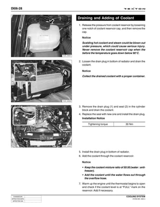
The section outlines key engine systems including intake, exhaust, lubrication, and cooling. It also describes engine controls and components. Cleanliness procedures are emphasized due to the precision of the direct injection fuel system. Vehicle identification numbers and specifications are included to aid technicians in service and repair.


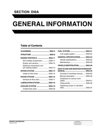


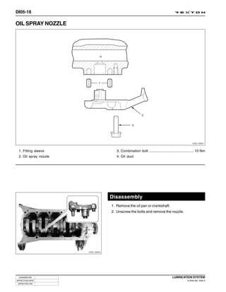
![DI0A-25
Specifications (Cont’d)
Systems Items Diesel Remark
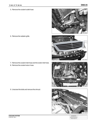
Transfercase Model Part-time ( ): optional item
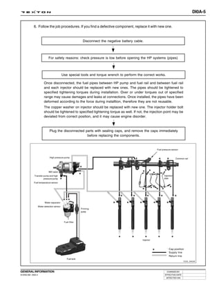
Type Planetary gear type
Gear ratio High 1.000 : 1
Low 2.483 : 1
Clutch Type Hydraulic [A/T: Torque converter]
Disc type Dry single diaphragm type
[A/T: 3 elements 1 stage 2 phases]
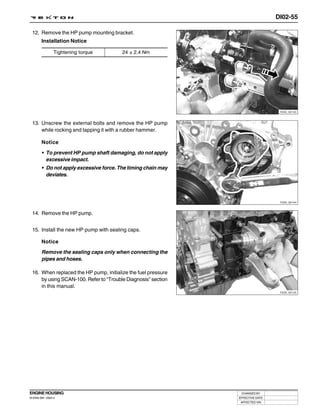
Power Type Rack and pinion
steering Steering angle Inner 36° 17'
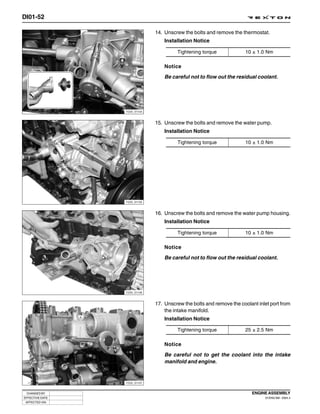
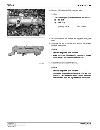
Outer 32° 40'
Front axle Drive shaft type Ball joint type
Axle housing type Build-up type
Rear axle Drive shaft type Semi-floating type
Axle housing type Build-up type
Brake Master cylinder type Tandem type
Booster type Vacuum booster
Type Inner Disc
Outer Drum (Disc)
Parking brake Cable type (internal expansion)
Suspension Front Wishbone + Coil spring
Rear 5-link + Coil spring
Air Refrigerant R134a
conditioner Compressor type Vane type
Electrical Battery type/Capacity (V-AH) MF / 12 - 90
Starter capacity (V-kW) Diesel : 12 - 2.2, Gasoline : 12 - 1.8
Alternator capacity (V-A) IDI 12 - 75 (12 - 90)
DI 12 - 140 (12 - 115)
Gasoline 12 - 115
GENERAL INFORMATION CHANGED BY
DI ENG SM - 2004.4 EFFECTIVE DATE
AFFECTED VIN](https://image.slidesharecdn.com/rextonservicemanualengine-100819164941-phpapp01/85/Rexton-service-manual-engine-29-320.jpg)

![DI0A-28
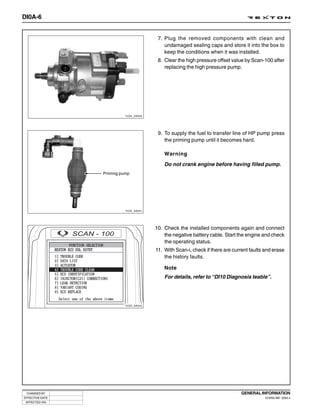
VEHICLE IDENTIFICATION
1. Vehicle identification Number
Vehicle identification number (VIN) is is on the right front
axle upper frame.
[KPTPOA19S1P 122357]
K .. Nation (K: Korea)
P .. Maker Identification (P: Ssangyong Motor Company)
T .. Vehicle Type (T: Passenger car - 4WD)
P .. Line Models (P: Rexton)
O . Body Type (O: 5-door)
A .. Trim Level (A: Standard, B: Deluxe,
Y220_0A018
C: Super deluxe)
1 .. Restraint System (0: No seatbelts, 1: 3-point
seatbelts, 2: 2-point seatbelt)
9 .. Engine Type (9: 3199cc, In-line 6 cylinders, Gasoline E32)
(D: 2874cc, Il-line 5 cylinders, Diesel)
S .. Check Digit (S: All area except North America)
1 .. Model Year (1: 2001, 2: 2002, 3: 2003)
P .. Plant Code (P: Pyungtaek plant)
122357 (Production serial number)
2. Certification Label
The certification label is affixed on the bottom of driver’s side
B-pillar.
Y220_0A019
CHANGED BY GENERAL INFORMATION
EFFECTIVE DATE DI ENG SM - 2004.4
AFFECTED VIN](https://image.slidesharecdn.com/rextonservicemanualengine-100819164941-phpapp01/85/Rexton-service-manual-engine-32-320.jpg)


![DI01-8
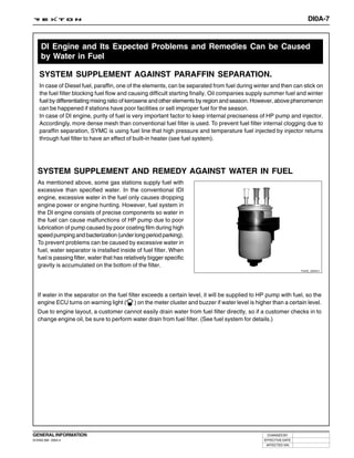
ENGINE PERFORMANCE CURVE
Output and Torque
Output [PS]
Torque [Nm]
Speed [rpm]
Y220_00025
CHANGED BY ENGINE ASSEMBLY
EFFECTIVE DATE DI ENG SM - 2004.4
AFFECTED VIN](https://image.slidesharecdn.com/rextonservicemanualengine-100819164941-phpapp01/85/Rexton-service-manual-engine-51-320.jpg)
![DI01-9
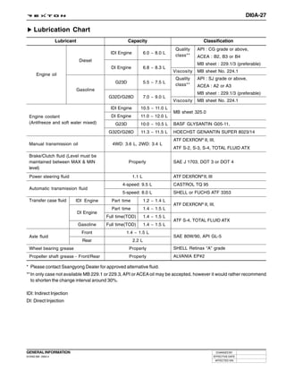
Oil Temperature/Pressure and Boost Pressure
Oil pressure [bar]
Oil temperature [C]
Boost pressure [bar]
Speed [rpm]
Y220_00026
ENGINE ASSEMBLY CHANGED BY
DI ENG SM - 2004.4 EFFECTIVE DATE
AFFECTED VIN](https://image.slidesharecdn.com/rextonservicemanualengine-100819164941-phpapp01/85/Rexton-service-manual-engine-52-320.jpg)


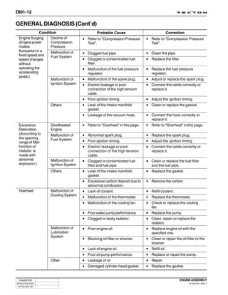


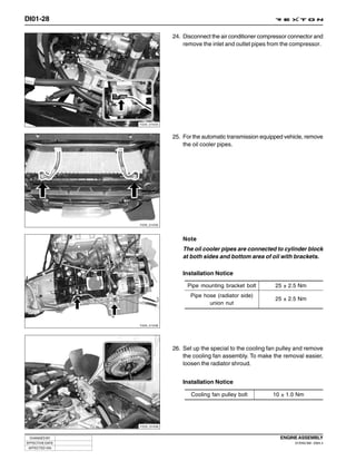


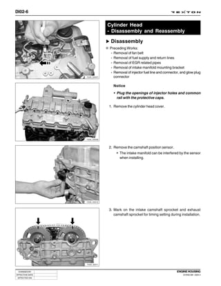


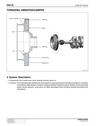


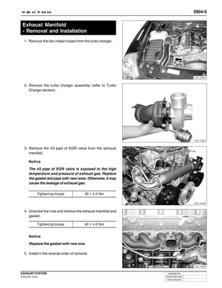
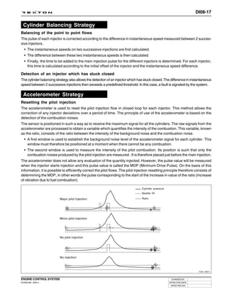
![DI02-43
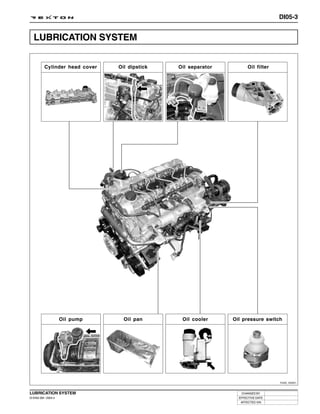
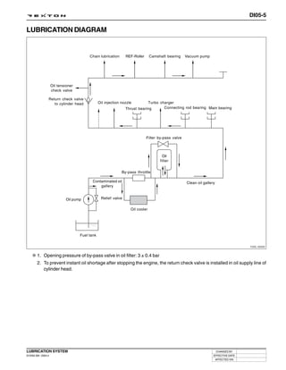
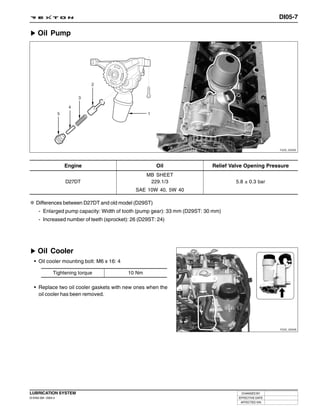
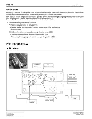
Structure
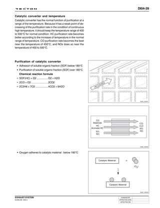
Function and characteristics
• When the output changes from the engine is high during
power stroke ( ): The damper absorbs the shocks to
reduce the changes to transmission.
• When the output changes from the engine is low during
compression stroke ( ): The damper increases the torque
changes to clutch.
<Example of DMF operation>
Y220_02112
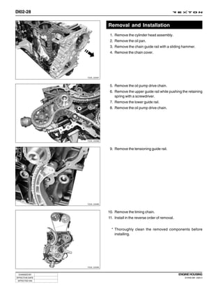
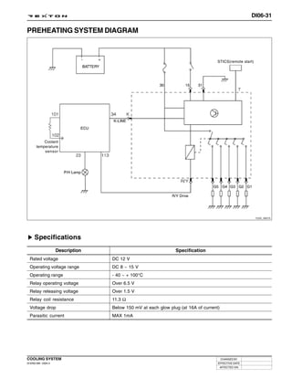
<Torque change curve of engine and drive shaft>
Angular acceleration amplitude [1/s 2]
Conventional system DMFW
Engine
Engine
Transmission
Transmission
Speed [rpm] Speed [rpm]
Y220_02113
System Characteristics
Function Advantages of DMF
• Filters irregularities of engine: The secondary flywheel • Improved torque response by using 3-stage type spring:
operates almost evenly so does not cause gear noises Strengthens the torque response in all ranges (low,
• The mass of the primary flywheel is less than medium, and high speed) by applying respective spring
conventional flywheel so the engine irregularity constant at each range.
increases more (less pulsation absorbing effect) • Stable revolution of the primary and secondary wheel
• Transmission protection function: Reduces the load to by using planetary gear: Works as auxiliary damper
powertrain (transmission) by blocking the irregularity against spring changes
of engine • Less heat generation due to no direct friction against
spring surface: Plastic material is covered on the spring
Characteristics of DMF outer surface
• Reduced vibration noise from the powertrain by blocking
• Increased durability by using plastic bushing (extends
the torsional vibrations
the lifetime of grease)
• Enhanced vehicle silence and riding comforts: reduced
engine torque changes
• Reduced shifting shocks
• Smooth acceleration and deceleration
ENGINE HOUSING CHANGED BY
DI ENG SM - 2004.4 EFFECTIVE DATE
AFFECTED VIN](https://image.slidesharecdn.com/rextonservicemanualengine-100819164941-phpapp01/85/Rexton-service-manual-engine-149-320.jpg)


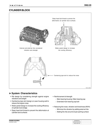
![DI10-4
SCAN-I OPERATING PROCEDURES - D27DT ENGINE
ENTERING DIAGNOSIS PROCEDURES
1. Select “1] DIAGNOSIS” and press “ ” in “MAIN MENU”
screen.
Y220_10001
2. Select “5] REXTON” and press “ ” in “VEHICLE
SELECTION” screen.
Y220_10002
3. Select “1] ECU” and press “ ” in “CONTROL UNIT
SELECTION” screen.
Y220_10003
CHANGED BY DIAGNOSIS
EFFECTIVE DATE DI ENG SM - 2004.4
AFFECTED VIN](https://image.slidesharecdn.com/rextonservicemanualengine-100819164941-phpapp01/85/Rexton-service-manual-engine-396-320.jpg)
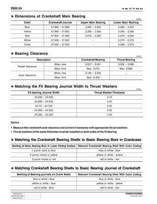
![DI10-5
4. Select “4] XDi 270” and press “ ” in “MODEL
SELECTION” screen.
Y220_10004
5. The “FUNCTION SELECTION” screen is displayed.
Y220_10005
DIAGNOSIS CHANGED BY
DI ENG SM - 2004.4 EFFECTIVE DATE
AFFECTED VIN](https://image.slidesharecdn.com/rextonservicemanualengine-100819164941-phpapp01/85/Rexton-service-manual-engine-397-320.jpg)
![DI10-6
FUNCTION SELECTION
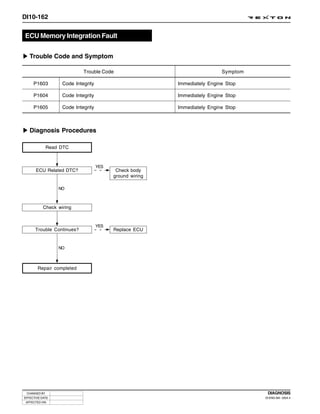
Check the Trouble Code
Preceding work: Perform the “Entering Diagnosis Proce-
dures”
Y220_10006
1. Select “1] TROUBLE CODE” and press “ENTER” in
“FUNCTION SELECTION” screen.
Y220_10007
2. The “DIAGNOSTIC TROUBLE CODEs” screen is
displayed and it shows the trouble.
Note
If there is not any fault, “NO TROUBLE DETECTED”
message appears.
Y220_10008
3. When selecting a trouble code, then
if you press “ ”: Displays the sensor data for the
detected trouble (Freeze Frame
Mode).
if you press “ ”: Displays the help tips for the
detected trouble.
Y220_10013
CHANGED BY DIAGNOSIS
EFFECTIVE DATE DI ENG SM - 2004.4
AFFECTED VIN](https://image.slidesharecdn.com/rextonservicemanualengine-100819164941-phpapp01/85/Rexton-service-manual-engine-398-320.jpg)
![DI10-7
Sensor Data Check
Preceding Work: Perform the “Entering Diagnosis Proce-
dures”
Y220_10010
1. Select “2] DATA LIST” and press “ ” in “FUNCTION
SELECTION” screen.
Y220_10011
2. The screen shows approx. 54 sensor data.
Y220_10012
3. Select the items you want to see and press “ ” key
to freeze them.
Note
You can freeze up to 5 items (*: selected items).
Y220_10013
DIAGNOSIS CHANGED BY
DI ENG SM - 2004.4 EFFECTIVE DATE
AFFECTED VIN](https://image.slidesharecdn.com/rextonservicemanualengine-100819164941-phpapp01/85/Rexton-service-manual-engine-399-320.jpg)
![DI10-8
Actuator Check
Preceding Work: Perform the “Entering Diagnosis Proce-
dures”
Y220_10014
1. Select “3] ACTUATOR” and press “ ” in “FUNCTION
SELECTION” screen.
Y220_10015
2. The screen shows 14 items. Select the item you want to
see and press “ ”.
Y220_10016
3. For example, if you select “02] GLOW PLUG” item and
press “ ”, the screen as shown in figure is displayed.
Y220_10017
CHANGED BY DIAGNOSIS
EFFECTIVE DATE DI ENG SM - 2004.4
AFFECTED VIN](https://image.slidesharecdn.com/rextonservicemanualengine-100819164941-phpapp01/85/Rexton-service-manual-engine-400-320.jpg)

![DI10-10
Trouble Code Clear
Preceding Work: Perform the “Entering Diagnosis Proce-
dures”
Y220_10020
1. Select “1] TROUBLE CODE” and press “ ” in
“FUNCTION SELECTION” screen.
Y220_10021
2. The “DIAGNOSTIC TROUBLE CODEs” screen is
displayed and it shows the trouble.
Note
C = Current trouble, H = History trouble
Y220_10022
3. Fix the trouble and go back to “1] TROUBLE CODE”
screen and check if the trouble has been changed to “H
(History trouble code)” code.
Y220_10023
CHANGED BY DIAGNOSIS
EFFECTIVE DATE DI ENG SM - 2004.4
AFFECTED VIN](https://image.slidesharecdn.com/rextonservicemanualengine-100819164941-phpapp01/85/Rexton-service-manual-engine-402-320.jpg)
![DI10-11
4. If the trouble has been change to “H (History trouble code)”
code, press “ ” key to go back to “FUNCTION
SELECTION” screen. In this screen, select “4] TROUBLE
CODE CLEAR” and press “ ”.
Y220_10024
5. The “TROUBLE CODE CLEAR” screen is displayed. If
you press “ ”, only the history trouble codes will be
cleared.
Note
• Current trouble codes will not be cleared.
• Check the trouble codes after clearing the trouble
codes.
Y220_10025
DIAGNOSIS CHANGED BY
DI ENG SM - 2004.4 EFFECTIVE DATE
AFFECTED VIN](https://image.slidesharecdn.com/rextonservicemanualengine-100819164941-phpapp01/85/Rexton-service-manual-engine-403-320.jpg)
![DI10-12
ECU Identification
Preceding Work: Perform the “Entering Diagnosis Proce-
dures”
Y220_10027
1. Select “1] ECU IDENTIFICATION” and press “ ” in
“FUNCTION SELECTION” screen.
Y220_10028
2. The “ECU IDENTIFICATION” screen that shows the VIN,
ECU software number, ECU software version and
programming date is displayed.
Y220_10029
3. If you replaced the ECU, press “ ” to input the vehicle
identification number.
Y220_10030
CHANGED BY DIAGNOSIS
EFFECTIVE DATE DI ENG SM - 2004.4
AFFECTED VIN](https://image.slidesharecdn.com/rextonservicemanualengine-100819164941-phpapp01/85/Rexton-service-manual-engine-404-320.jpg)
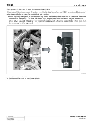
![DI10-13
Injector Coding (C2I)
Preceding Work: Perform the “Entering Diagnosis Proce-
dures”
Notice
If the injector/ECU has been replaced or the injector system
defective is suspected, go to C2I Coding item and check
the injector and coded injector C2I value.
Y220_10031
1. Select “6] INJECTOR (C2I) CORRECTIONS” and press
“ ” in “FUNCTION SELECTION” screen.
Y220_10032
2. The “INJECTOR (C2I) CORRECTIONS” screen that shows
current C2I coding values of #1 to #5 injector is displayed.
3. If you replaced the ECU, enter the C2I value of the relevant
injector.
Y220_10033
Note
• The C2I value of replacing injector is recorded in
the label.
• C2I coding number: 16 digits (ex, B1 B9 D4 1B 43
C6 0E 4F)
Y220_10034
DIAGNOSIS CHANGED BY
DI ENG SM - 2004.4 EFFECTIVE DATE
AFFECTED VIN](https://image.slidesharecdn.com/rextonservicemanualengine-100819164941-phpapp01/85/Rexton-service-manual-engine-405-320.jpg)

![DI10-15
Leak Detection
Preceding Work: Perform the “Entering Diagnosis Proce-
dures”
Note
This item is for checking the high fuel pressure after the
IMV supply line of HP pump in DI engine fuel system. If
you still suspect that the fuel pressure system is defective
even after no trouble is detected, perform the fuel pressure
test again by using a fuel pressure tool kit.
Y220_10037
1. Select “7] LEAK DETECTION” and press “ ” in
“FUNCTION SELECTION” screen.
Y220_10038
2. The “LEAK DETECTION” screen that shows the checking
conditions as shown in figure is displayed.
Y220_10040
DIAGNOSIS CHANGED BY
DI ENG SM - 2004.4 EFFECTIVE DATE
AFFECTED VIN](https://image.slidesharecdn.com/rextonservicemanualengine-100819164941-phpapp01/85/Rexton-service-manual-engine-407-320.jpg)
![DI10-16
Variant Coding
Preceding Work: Perform the “Entering Diagnosis Proce-
dures”
Y220_10041
1. Select “8] VARIANT CODING” and press “ ” in
“FUNCTION SELECTION” screen.
Y220_10042
2. When the “VARIANT CODING” screen is displayed,
select “1] READ VARIANT VALUE” and press “ ”.
Y220_10043
3. The “VARIANT CODING” screen that shows currently
equipped devices is displayed.
Y220_10044
CHANGED BY DIAGNOSIS
EFFECTIVE DATE DI ENG SM - 2004.4
AFFECTED VIN](https://image.slidesharecdn.com/rextonservicemanualengine-100819164941-phpapp01/85/Rexton-service-manual-engine-408-320.jpg)
![DI10-17
4. If you need to change the variant coding, press “ ”
key to go back to “VARIANT CODING” screen. In the
screen, select “2] WRITE VARIANT CODING” and press
“ ”.
Y220_10045
5. When the “VARIANT CODING” screen is displayed,
change the item by using arrow keys.
Y220_10046
6. If you press “ ”, the message as shown in figure
appears. And, then “VARIANT CODING” screen is
displayed.
7. Select “READ VARIANT VALUE” to see the coding coded
value.
Y220_10047
DIAGNOSIS CHANGED BY
DI ENG SM - 2004.4 EFFECTIVE DATE
AFFECTED VIN](https://image.slidesharecdn.com/rextonservicemanualengine-100819164941-phpapp01/85/Rexton-service-manual-engine-409-320.jpg)
![DI10-18
ECU Replace
Preceding Work: Perform the “Entering Diagnosis Proce-
dures”
1. Select “9] ECU REPLACE” and press “ ” in
“FUNCTION SELECTION” screen.
Y220_10048
2. When the “ECU REPLACE (STEP 2)” screen is displayed
followed by “ECU REPLACE (STEP 1) screen, turn the
ignition “OFF” and remove the currently installed ECU.
Notice
Do not turn off the Scan-100 at this time.
Record the below data:
- Vehicle identification number
- Variant coding value
- C2I coding value
Y220_10049 - Multi calibration
3. Install the new ECU.
Y220_10050
CHANGED BY DIAGNOSIS
EFFECTIVE DATE DI ENG SM - 2004.4
AFFECTED VIN](https://image.slidesharecdn.com/rextonservicemanualengine-100819164941-phpapp01/85/Rexton-service-manual-engine-410-320.jpg)
![DI10-19
4. If you turn the ignition switch to “ON” position and press “ ”, the message as shown in figure 1 (system
initialization) appears, and then “MULTI CALIBRATION SELECTION” screen (fig. 2) is displayed.
figure 1 figure 2
Y220_10051
5. In “MULTI CALIBRATION SELECTION” screen, select “2]
DOM/GEN” for automatic transmission equipped vehicle
and select “4] DOM/GEN” for manual transmission
equipped vehicle.
Y220_10052
6. When you press “ ”, the processing message as
shown in figure appears.
Y220_10051A
DIAGNOSIS CHANGED BY
DI ENG SM - 2004.4 EFFECTIVE DATE
AFFECTED VIN](https://image.slidesharecdn.com/rextonservicemanualengine-100819164941-phpapp01/85/Rexton-service-manual-engine-411-320.jpg)