Download as PDF, PPTX


![high data rate links in emergencies.[2]
Satellites
The problem of building a reliable network using
satellites is somewhat similar to that of building a
communications network with unreliable links. When
a satellite is overhead, the link is operative. When a
satellite is not overhead, the link is out of service.
Thus, such links are highly compatible with the type
of system to be described.
Variable Data Rate Links
In a conventional circuit switched system each of the
tandem links requires matched transmission
bandwidths. In order to make fullest use of a digital
link, the post-error-removal data rate would have to
vary, as it is a function of noise level. The problem
then is to build a communication network made up of
links of variable data rate to use the communication
resource most efficiently.
Variable Data Rate Users
We can view both the links and the entry point nodes
of a multiple-user all-digital communications system
as elements operating at an ever changing data rate.
From instant to instant the demand for transmission
will vary.
We would like to take advantage of the average
demand over all users instead of having to allocate a
full peak demand channel to each. Bits can become a
common denominator of loading for economic
charging of customers. We would like to efficiently
Paul Baran‘62 On Distributed Communications Networks
ON A FUTURE SYST E M
DEVELOPMENT](https://image.slidesharecdn.com/pwl2-160607180433/85/Resource-Allocation-in-Computer-Networks-38-320.jpg)
![high data rate links in emergencies.[2]
Satellites
The problem of building a reliable network using
satellites is somewhat similar to that of building a
communications network with unreliable links. When
a satellite is overhead, the link is operative. When a
satellite is not overhead, the link is out of service.
Thus, such links are highly compatible with the type
of system to be described.
Variable Data Rate Links
In a conventional circuit switched system each of the
tandem links requires matched transmission
bandwidths. In order to make fullest use of a digital
link, the post-error-removal data rate would have to
vary, as it is a function of noise level. The problem
then is to build a communication network made up of
links of variable data rate to use the communication
resource most efficiently.
Variable Data Rate Users
We can view both the links and the entry point nodes
of a multiple-user all-digital communications system
as elements operating at an ever changing data rate.
From instant to instant the demand for transmission
will vary.
We would like to take advantage of the average
demand over all users instead of having to allocate a
full peak demand channel to each. Bits can become a
common denominator of loading for economic
charging of customers. We would like to efficiently
Paul Baran‘62 On Distributed Communications Networks
ON A FUTURE SYST E M
DEVELOPMENT](https://image.slidesharecdn.com/pwl2-160607180433/85/Resource-Allocation-in-Computer-Networks-39-320.jpg)


![A protocol that supports the sharing of resources that
exist in different packet switching networks is
presented. The protocol provides for variation in
individual network packet sizes, transmission failures,
sequencing, flow control, end-to-end error checking,
and the creation and destruction of logical process-
to-process connections. Some implementation issues
are considered, and problems such as internetwork
routing, accounting, and timeouts are exposed.
In the last few years considerable effort has been
expended on the design and implementation of
packet switching networks [1]-[7],[14],[17]. A principle
reason for developing such networks has been to
facilitate the sharing of computer resources. A packet
communication network includes a transportation
mechanism for delivering data between computers or
between computers and terminals. To make the data
meaningful, computer and terminals share a common
protocol (i.e, a set of agreed upon conventions).
Several protocols have already been developed for this
purpose [8]-[12],[16]. However, these protocols have
Vinton G. Cerf and Robert E. Kahn‘74 A Protocol for Packet Network Intercommunication
ABSTRACT
INTRODUCTION](https://image.slidesharecdn.com/pwl2-160607180433/85/Resource-Allocation-in-Computer-Networks-55-320.jpg)
![In the last few years considerable effort has been
expended on the design and implementation of
packet switching networks [1]-[7],[14],[17]. A principle
reason for developing such networks has been to
facilitate the sharing of computer resources. A packet
communication network includes a transportation
mechanism for delivering data between computers or
between computers and terminals. To make the data
meaningful, computer and terminals share a common
protocol (i.e, a set of agreed upon conventions).
Several protocols have already been developed for this
purpose [8]-[12],[16]. However, these protocols have
Vinton G. Cerf and Robert E. Kahn‘74 A Protocol for Packet Network Intercommunication
ABSTRACT
INTRODUCTION
A protocol that supports the sharing of resources that
exist in different packet switching networks is
presented. The protocol provides for variation in
individual network packet sizes, transmission failures,
sequencing, flow control, end-to-end error checking,
and the creation and destruction of logical process-
to-process connections. Some implementation issues
are considered, and problems such as internetwork
routing, accounting, and timeouts are exposed.](https://image.slidesharecdn.com/pwl2-160607180433/85/Resource-Allocation-in-Computer-Networks-56-320.jpg)
![In the last few years considerable effort has been
expended on the design and implementation of
packet switching networks [1]-[7],[14],[17]. A principle
reason for developing such networks has been to
facilitate the sharing of computer resources. A packet
communication network includes a transportation
mechanism for delivering data between computers or
between computers and terminals. To make the data
meaningful, computer and terminals share a common
protocol (i.e, a set of agreed upon conventions).
Several protocols have already been developed for this
purpose [8]-[12],[16]. However, these protocols have
Vinton G. Cerf and Robert E. Kahn‘74 A Protocol for Packet Network Intercommunication
ABSTRACT
INTRODUCTION
“A protocol that supports the
sharing of resources that exist in
different packet switching
networks is presented.”
A protocol that supports the sharing of resources that
exist in different packet switching networks is
presented. The protocol provides for variation in
individual network packet sizes, transmission failures,
sequencing, flow control, end-to-end error checking,
and the creation and destruction of logical process-
to-process connections. Some implementation issues
are considered, and problems such as internetwork
routing, accounting, and timeouts are exposed.](https://image.slidesharecdn.com/pwl2-160607180433/85/Resource-Allocation-in-Computer-Networks-57-320.jpg)
![A protocol that supports the sharing of resources that
exist in different packet switching networks is
presented. The protocol provides for variation in
individual network packet sizes, transmission failures,
sequencing, flow control, end-to-end error checking,
and the creation and destruction of logical process-
to-process connections. Some implementation issues
are considered, and problems such as internetwork
routing, accounting, and timeouts are exposed.
In the last few years considerable effort has been
expended on the design and implementation of
packet switching networks [1]-[7],[14],[17]. A principle
reason for developing such networks has been to
facilitate the sharing of computer resources. A packet
communication network includes a transportation
mechanism for delivering data between computers or
between computers and terminals. To make the data
meaningful, computer and terminals share a common
protocol (i.e, a set of agreed upon conventions).
Several protocols have already been developed for this
purpose [8]-[12],[16]. However, these protocols have
Vinton G. Cerf and Robert E. Kahn‘74 A Protocol for Packet Network Intercommunication
ABSTRACT
INTRODUCTION
packet fragmentation
transmission failures
sequencing
flow control
error checking
connection setup](https://image.slidesharecdn.com/pwl2-160607180433/85/Resource-Allocation-in-Computer-Networks-58-320.jpg)


![incorporated. We envision it will occasionally be
invoked to allow HOST accommodation to
infrequent overdemands for limited buffer resources,
and otherwise not used much.
Any retransmission policy requires some means by
which the receiver can detect duplicate arrivals. Even
if an infinite number of distinct packet sequence
numbers were available, the receiver would still have
the problem of knowing how long to remember
previously received packets in order to detect
duplicates. Matters are complicated by the fact that
only a finite number of distinct sequence numbers are
in fact available, and if they are reused, the receiver
must be able to distinguish between new
transmissions and retransmissions.
A window strategy, similar to that used by the French
CYCLADES system (voie virtuelle transmission
mode [8]) and the ARPANET very distant HOST
connection [18]), is proposed here (see Fig. 10).
Suppose that the sequence number field in the
internetwork header permits sequence numbers to
range from 0 to n − 1. We assume that the sender will
not transmit more than w bytes without receiving an
acknowledgment. The w bytes serve as the window
(see Fig. 11). Clearly, w must be less than n. The rules
for sender and receiver are as follows.
Sender: Let L be the sequence number associated
with the left window edge.
1) The sender transmits bytes from segments whose
text lies between L and up to L + w − 1.
Vinton G. Cerf and Robert E. Kahn‘74 A Protocol for Packet Network Intercommunication
RETRANSMISSION A N D
DUPLICATE DETEC TI ON
NETWORK INTERCOMMUNICATION 643
SSIONANDDUPLICATE
DETECTION
e 100 percent reliable. We
d positive acknowledgment mecha-
TCP’s torecover from packet losses
other. A TCP transmits packets and
knowledgements) that are carried in
eam. If noacknowledgment for a
received, theTCP will retransmit.
that the HOST level retransmission
s described inthe following para-
called uponveryofteninpractice.
sts2 that individual networks can be
d without this feature. However, the
retransmissioncapabilitymakes it
om occasional network problems and
of HOST protocol strategies to be in-
ion it will occasionally be invoked to
dation to infrequent overdemandsfor
es, and otherwise not used much.
Left Window Edge
I
0 n-1a+w- 1a
1- window -4
I< packet sequence number space
-1
Fig. 10. The windowconcept.
Source
Address
I Address
Destination
I
6
7
8
9
10
Next Read Position
End ReadPosition
Timeout
Fig. 11. Conceptual TCBformat.](https://image.slidesharecdn.com/pwl2-160607180433/85/Resource-Allocation-in-Computer-Networks-72-320.jpg)
![On retransmission, the same packet might be broken
into three 200-byte packets going through a different
HOST. Since each byte has a sequence number, there
is no confusion at the receiving TCP. We leave for
later the issue of initially synchronizing the sender
and receiver left window edges and the window size.
Every segment that arrives at the destination TCP is
ultimately acknowlegded by returning the sequence
number of the next segment which must be passed to
the process (it may not yet have arrived).
Earlier we described the use of a sequence number
space and window to aid in duplicate detection.
Acknowledgments are carried in the process header
(see Fig. 6) and along with them there is provision for
a “suggested window” which the receiver can use to
control the flow of data from the sender. This is
intended to be the main component of the process
flow control mechanism. The receiver is free to vary
the window size according to any algorithm it desires
so long as the window size never exceeds half the
sequence number space.
This flow control mechanism is exceedingly powerful
and flexible and does not suffer from synchronization
troubles that may be encountered by incremental
buffer allocation schemes [9], [10]. However, it relies
heavily on an effective retransmission strategy. The
receiver can reduce the window even while packets
are en route from the sender whose window is
presently larger. The net effect of this reduction will
be that the receiver may discard incoming packets
(they may be outside the window) and reiterate the
Vinton G. Cerf and Robert E. Kahn‘74 A Protocol for Packet Network Intercommunication
NETWORK INTERCOMMUNICATION 643
SSIONANDDUPLICATE
DETECTION
e 100 percent reliable. We
d positive acknowledgment mecha-
TCP’s torecover from packet losses
other. A TCP transmits packets and
knowledgements) that are carried in
eam. If noacknowledgment for a
received, theTCP will retransmit.
that the HOST level retransmission
s described inthe following para-
called uponveryofteninpractice.
sts2 that individual networks can be
d without this feature. However, the
retransmissioncapabilitymakes it
om occasional network problems and
of HOST protocol strategies to be in-
ion it will occasionally be invoked to
dation to infrequent overdemandsfor
es, and otherwise not used much.
Left Window Edge
I
0 n-1a+w- 1a
1- window -4
I< packet sequence number space
-1
Fig. 10. The windowconcept.
Source
Address
I Address
Destination
I
6
7
8
9
10
Next Read Position
End ReadPosition
Timeout
Fig. 11. Conceptual TCBformat.
“a ‘suggested window’ which
the receiver can use to control
the flow of data from the sender.
This is intended to be the main
component of the process flow
control mechanism.”
FLOW CONTROL](https://image.slidesharecdn.com/pwl2-160607180433/85/Resource-Allocation-in-Computer-Networks-73-320.jpg)


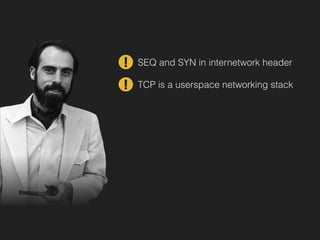
![(vii) fast retransmit
Our measurements and the reports of beta testers
suggest that the final product is fairly good at dealing
with congested conditions on the Internet.
This paper is a brief description of (i) - (v) and the
rationale behind them. (vi) is an algorithm recently
developed by Phil Karn of Bell Communications
Research, described in [KP87]. (vii) is described in a
soon-to-be-published RFC.
Algorithms (i) - (v) spring from one observation: The
flow on a TCP connection (or ISO TP-4 or Xerox NS
SPP connection) should obey a 'conservation of
packets' principle. And, if this principle were obeyed,
congestion collapse would become the exception
rather than the rule. Thus congestion control involves
finding places that violate conservation and fixing
them.
By 'conservation of packets' I mean that for a
connection 'in equilibrium', i.e., running stably with a
full window of data in transit, the packet flow is what
a physicist would call 'conservative': A new packet
isn't put into the network until an old packet leaves.
The physics of flow predicts that systems with this
property should be robust in the face of congestion.
Observation of the Internet suggests that it was not
particularly robust. Why the discrepancy?
There are only three ways for packet conservation to
fail:
1. The connection doesn't get to equilibrium, or
2. A sender injects a new packet before an old packet
has exited, or
3. The equilibrium can't be reached because of
Van Jacobson‘88 Congestion Avoidance and Control](https://image.slidesharecdn.com/pwl2-160607180433/85/Resource-Allocation-in-Computer-Networks-99-320.jpg)
![(vii) fast retransmit
Our measurements and the reports of beta testers
suggest that the final product is fairly good at dealing
with congested conditions on the Internet.
This paper is a brief description of (i) - (v) and the
rationale behind them. (vi) is an algorithm recently
developed by Phil Karn of Bell Communications
Research, described in [KP87]. (vii) is described in a
soon-to-be-published RFC.
Algorithms (i) - (v) spring from one observation: The
flow on a TCP connection (or ISO TP-4 or Xerox NS
SPP connection) should obey a 'conservation of
packets' principle. And, if this principle were obeyed,
congestion collapse would become the exception
rather than the rule. Thus congestion control involves
finding places that violate conservation and fixing
them.
By 'conservation of packets' I mean that for a
connection 'in equilibrium', i.e., running stably with a
full window of data in transit, the packet flow is what
a physicist would call 'conservative': A new packet
isn't put into the network until an old packet leaves.
The physics of flow predicts that systems with this
property should be robust in the face of congestion.
Observation of the Internet suggests that it was not
particularly robust. Why the discrepancy?
There are only three ways for packet conservation to
fail:
1. The connection doesn't get to equilibrium, or
2. A sender injects a new packet before an old packet
has exited, or
3. The equilibrium can't be reached because of
Van Jacobson‘88 Congestion Avoidance and Control
“(…) should obey a
‘conservation of packets’
principle”](https://image.slidesharecdn.com/pwl2-160607180433/85/Resource-Allocation-in-Computer-Networks-100-320.jpg)
![(vii) fast retransmit
Our measurements and the reports of beta testers
suggest that the final product is fairly good at dealing
with congested conditions on the Internet.
This paper is a brief description of (i) - (v) and the
rationale behind them. (vi) is an algorithm recently
developed by Phil Karn of Bell Communications
Research, described in [KP87]. (vii) is described in a
soon-to-be-published RFC.
Algorithms (i) - (v) spring from one observation: The
flow on a TCP connection (or ISO TP-4 or Xerox NS
SPP connection) should obey a 'conservation of
packets' principle. And, if this principle were obeyed,
congestion collapse would become the exception
rather than the rule. Thus congestion control involves
finding places that violate conservation and fixing
them.
By 'conservation of packets' I mean that for a
connection 'in equilibrium', i.e., running stably with a
full window of data in transit, the packet flow is what
a physicist would call 'conservative': A new packet
isn't put into the network until an old packet leaves.
The physics of flow predicts that systems with this
property should be robust in the face of congestion.
Observation of the Internet suggests that it was not
particularly robust. Why the discrepancy?
There are only three ways for packet conservation to
fail:
1. The connection doesn't get to equilibrium, or
2. A sender injects a new packet before an old packet
has exited, or
3. The equilibrium can't be reached because of
“(…) for a connection 'in
equilibrium', (…) the packet flow
is what a physicist would call
'conservative': A new packet
isn't put into the network until an
old packet leaves.”
Van Jacobson‘88 Congestion Avoidance and Control
“(…) should obey a
‘conservation of packets’
principle”](https://image.slidesharecdn.com/pwl2-160607180433/85/Resource-Allocation-in-Computer-Networks-101-320.jpg)


![Van Jacobson‘88 Congestion Avoidance and Control
is costly. But an exponential, almost regardless of its
time constant, increases so quickly that overestimates
are inevitable.
Without justification, I'll state that the best increase
policy is to make small, constant changes to the window
size:
On no congestion:
W~= W~_~+ ~ (~ << Wmo=)
where W,.,,a= is the pipesize (the delay-bandwidth prod-
uct of the path minus protocol overhead -- i.e., the
largest sensible window for the unloaded path). This
is the additive increase / multiplicative decrease policy
suggested in [JRC87] and the policy we've implemented
in TCP. The only difference between the two implemen-
tations is the choice of constants for d and u. We used
0.5 and I for reasons partially explained in appendix C.
A more complete analysis is in yet another in-progress
paper.
The preceding has probably made the congestion
control algorithm sound hairy but it's not. Like slow-
to slo
both c
by a ti
dow, t
depen
tives.
have b
tise th
descri
algori
Fig
nectio
thoug
delibe
nario
IMP en
in tran
4.3BSD
multa
at Ber
the bu
lead 12](https://image.slidesharecdn.com/pwl2-160607180433/85/Resource-Allocation-in-Computer-Networks-108-320.jpg)
![Van Jacobson‘88 Congestion Avoidance and Control
is costly. But an exponential, almost regardless of its
time constant, increases so quickly that overestimates
are inevitable.
Without justification, I'll state that the best increase
policy is to make small, constant changes to the window
size:
On no congestion:
W~= W~_~+ ~ (~ << Wmo=)
where W,.,,a= is the pipesize (the delay-bandwidth prod-
uct of the path minus protocol overhead -- i.e., the
largest sensible window for the unloaded path). This
is the additive increase / multiplicative decrease policy
suggested in [JRC87] and the policy we've implemented
in TCP. The only difference between the two implemen-
tations is the choice of constants for d and u. We used
0.5 and I for reasons partially explained in appendix C.
A more complete analysis is in yet another in-progress
paper.
The preceding has probably made the congestion
control algorithm sound hairy but it's not. Like slow-
to slo
both c
by a ti
dow, t
depen
tives.
have b
tise th
descri
algori
Fig
nectio
thoug
delibe
nario
IMP en
in tran
4.3BSD
multa
at Ber
the bu
lead 12
u = 1](https://image.slidesharecdn.com/pwl2-160607180433/85/Resource-Allocation-in-Computer-Networks-109-320.jpg)
![Van Jacobson‘88 Congestion Avoidance and Control
(These are the first two terms in a Taylor series expan-
sion of L(t). There is reason to believe one might even-
tually need a three term, second order model, but not
until the Internet has grown substantially.)
When the network is congested, 7 must be large and
the queue lengths will start increasing exponentially, s
The system will stabilize only if the traffic sources throt-
tle back at least as quickly as the queues are growing.
Since a source controls load in a window-based proto-
col by adjusting the size of the window, W, we end up
with the sender policy
On congestion:
Wi = dWi_l (d < 1)
I.e., a multiplicative decrease of the window size (which
becomes an exponential decrease over time if the con-
gestion persists).
If there's no congestion, 7 must be near zero and the
load approximately constant. The network announces,
via a dropped packet, when demand is excessive but
utili
have
verg
able
widt
crea
T
tive
Wi =
will
thro
tedio
easy
to re
effec
9I
the s
will f
shrink
bottle
of co
move
is costly. But an exponential, almost regardless of its
time constant, increases so quickly that overestimates
are inevitable.
Without justification, I'll state that the best increase
policy is to make small, constant changes to the window
size:
On no congestion:
W~= W~_~+ ~ (~ << Wmo=)
where W,.,,a= is the pipesize (the delay-bandwidth prod-
uct of the path minus protocol overhead -- i.e., the
largest sensible window for the unloaded path). This
is the additive increase / multiplicative decrease policy
suggested in [JRC87] and the policy we've implemented
in TCP. The only difference between the two implemen-
tations is the choice of constants for d and u. We used
0.5 and I for reasons partially explained in appendix C.
A more complete analysis is in yet another in-progress
paper.
The preceding has probably made the congestion
control algorithm sound hairy but it's not. Like slow-
to slo
both c
by a ti
dow, t
depen
tives.
have b
tise th
descri
algori
Fig
nectio
thoug
delibe
nario
IMP en
in tran
4.3BSD
multa
at Ber
the bu
lead 12
u = 1](https://image.slidesharecdn.com/pwl2-160607180433/85/Resource-Allocation-in-Computer-Networks-110-320.jpg)
![Van Jacobson‘88 Congestion Avoidance and Control
(These are the first two terms in a Taylor series expan-
sion of L(t). There is reason to believe one might even-
tually need a three term, second order model, but not
until the Internet has grown substantially.)
When the network is congested, 7 must be large and
the queue lengths will start increasing exponentially, s
The system will stabilize only if the traffic sources throt-
tle back at least as quickly as the queues are growing.
Since a source controls load in a window-based proto-
col by adjusting the size of the window, W, we end up
with the sender policy
On congestion:
Wi = dWi_l (d < 1)
I.e., a multiplicative decrease of the window size (which
becomes an exponential decrease over time if the con-
gestion persists).
If there's no congestion, 7 must be near zero and the
load approximately constant. The network announces,
via a dropped packet, when demand is excessive but
utili
have
verg
able
widt
crea
T
tive
Wi =
will
thro
tedio
easy
to re
effec
9I
the s
will f
shrink
bottle
of co
move
is costly. But an exponential, almost regardless of its
time constant, increases so quickly that overestimates
are inevitable.
Without justification, I'll state that the best increase
policy is to make small, constant changes to the window
size:
On no congestion:
W~= W~_~+ ~ (~ << Wmo=)
where W,.,,a= is the pipesize (the delay-bandwidth prod-
uct of the path minus protocol overhead -- i.e., the
largest sensible window for the unloaded path). This
is the additive increase / multiplicative decrease policy
suggested in [JRC87] and the policy we've implemented
in TCP. The only difference between the two implemen-
tations is the choice of constants for d and u. We used
0.5 and I for reasons partially explained in appendix C.
A more complete analysis is in yet another in-progress
paper.
The preceding has probably made the congestion
control algorithm sound hairy but it's not. Like slow-
to slo
both c
by a ti
dow, t
depen
tives.
have b
tise th
descri
algori
Fig
nectio
thoug
delibe
nario
IMP en
in tran
4.3BSD
multa
at Ber
the bu
lead 12
u = 1
d = 0.5](https://image.slidesharecdn.com/pwl2-160607180433/85/Resource-Allocation-in-Computer-Networks-111-320.jpg)
![is costly. But an exponential, almost regardless of its
time constant, increases so quickly that overestimates
are inevitable.
Without justification, I'll state that the best increase
policy is to make small, constant changes to the window
size:
On no congestion:
W~= W~_~+ ~ (~ << Wmo=)
where W,.,,a= is the pipesize (the delay-bandwidth prod-
uct of the path minus protocol overhead -- i.e., the
largest sensible window for the unloaded path). This
is the additive increase / multiplicative decrease policy
suggested in [JRC87] and the policy we've implemented
in TCP. The only difference between the two implemen-
tations is the choice of constants for d and u. We used
to slow-start in addition to the above. But, because
both congestion avoidance and slow-start are triggered
by a timeout and both manipulate the congestion win-
dow, they are frequently confused. They are actually in-
dependent algorithms with completely different objec-
tives. To emphasize the difference, the two algorithms
have been presented separately even though in prac-
tise they should be implemented together. Appendix B
describes a combined slow-start/congestion avoidance
algorithm. 11
Figures 7 through 12 show the behavior of TCP con-
nections with and without congestion avoidance. Al-
though the test conditions (e.g., 16 KB windows) were
deliberately chosen to stimulate congestion, the test sce-
nario isn't far from common practice: The Arpanet
IMP end-to-end protocol allows at most eight packets
in transit between any pair of gateways. The default
The first thought is to use a symmetric, multiplicative
increase, possibly with a longer time constant, Wi =
bWi-1, 1 < b <1/d. This is a mistake. The result will
oscillate wildly and, on the average, deliver poor
throughput. There is an analytic reason for this but
it's tedious to derive. It has to do with that fact that it
is easy to drive the net into saturation but hard for
the net to recover (what [Kle76], chap. 2.1, calls the
rush-hour effect).9 Thus overestimating the available
bandwidth is costly. But an exponential, almost
regardless of its time constant, increases so quickly
that overestimates are inevitable.
Without justification, I'll state that the best increase
policy is to make small, constant changes to the
window size:
Van Jacobson‘88 Congestion Avoidance and Control
ADAPTING TO THE PATH :
CONGESTION AVOI DAN C E](https://image.slidesharecdn.com/pwl2-160607180433/85/Resource-Allocation-in-Computer-Networks-112-320.jpg)
![is costly. But an exponential, almost regardless of its
time constant, increases so quickly that overestimates
are inevitable.
Without justification, I'll state that the best increase
policy is to make small, constant changes to the window
size:
On no congestion:
W~= W~_~+ ~ (~ << Wmo=)
where W,.,,a= is the pipesize (the delay-bandwidth prod-
uct of the path minus protocol overhead -- i.e., the
largest sensible window for the unloaded path). This
is the additive increase / multiplicative decrease policy
suggested in [JRC87] and the policy we've implemented
in TCP. The only difference between the two implemen-
tations is the choice of constants for d and u. We used
to slow-start in addition to the above. But, because
both congestion avoidance and slow-start are triggered
by a timeout and both manipulate the congestion win-
dow, they are frequently confused. They are actually in-
dependent algorithms with completely different objec-
tives. To emphasize the difference, the two algorithms
have been presented separately even though in prac-
tise they should be implemented together. Appendix B
describes a combined slow-start/congestion avoidance
algorithm. 11
Figures 7 through 12 show the behavior of TCP con-
nections with and without congestion avoidance. Al-
though the test conditions (e.g., 16 KB windows) were
deliberately chosen to stimulate congestion, the test sce-
nario isn't far from common practice: The Arpanet
IMP end-to-end protocol allows at most eight packets
in transit between any pair of gateways. The default
The first thought is to use a symmetric, multiplicative
increase, possibly with a longer time constant, Wi =
bWi-1, 1 < b <1/d. This is a mistake. The result will
oscillate wildly and, on the average, deliver poor
throughput. There is an analytic reason for this but
it's tedious to derive. It has to do with that fact that it
is easy to drive the net into saturation but hard for
the net to recover (what [Kle76], chap. 2.1, calls the
rush-hour effect).9 Thus overestimating the available
bandwidth is costly. But an exponential, almost
regardless of its time constant, increases so quickly
that overestimates are inevitable.
Without justification, I'll state that the best increase
policy is to make small, constant changes to the
window size:
Van Jacobson‘88 Congestion Avoidance and Control
“There is an analytic reason for
this but it's tedious to derive.”
ADAPTING TO THE PATH :
CONGESTION AVOI DAN C E](https://image.slidesharecdn.com/pwl2-160607180433/85/Resource-Allocation-in-Computer-Networks-113-320.jpg)
![is costly. But an exponential, almost regardless of its
time constant, increases so quickly that overestimates
are inevitable.
Without justification, I'll state that the best increase
policy is to make small, constant changes to the window
size:
On no congestion:
W~= W~_~+ ~ (~ << Wmo=)
where W,.,,a= is the pipesize (the delay-bandwidth prod-
uct of the path minus protocol overhead -- i.e., the
largest sensible window for the unloaded path). This
is the additive increase / multiplicative decrease policy
suggested in [JRC87] and the policy we've implemented
in TCP. The only difference between the two implemen-
tations is the choice of constants for d and u. We used
to slow-start in addition to the above. But, because
both congestion avoidance and slow-start are triggered
by a timeout and both manipulate the congestion win-
dow, they are frequently confused. They are actually in-
dependent algorithms with completely different objec-
tives. To emphasize the difference, the two algorithms
have been presented separately even though in prac-
tise they should be implemented together. Appendix B
describes a combined slow-start/congestion avoidance
algorithm. 11
Figures 7 through 12 show the behavior of TCP con-
nections with and without congestion avoidance. Al-
though the test conditions (e.g., 16 KB windows) were
deliberately chosen to stimulate congestion, the test sce-
nario isn't far from common practice: The Arpanet
IMP end-to-end protocol allows at most eight packets
in transit between any pair of gateways. The default
The first thought is to use a symmetric, multiplicative
increase, possibly with a longer time constant, Wi =
bWi-1, 1 < b <1/d. This is a mistake. The result will
oscillate wildly and, on the average, deliver poor
throughput. There is an analytic reason for this but
it's tedious to derive. It has to do with that fact that it
is easy to drive the net into saturation but hard for
the net to recover (what [Kle76], chap. 2.1, calls the
rush-hour effect).9 Thus overestimating the available
bandwidth is costly. But an exponential, almost
regardless of its time constant, increases so quickly
that overestimates are inevitable.
Without justification, I'll state that the best increase
policy is to make small, constant changes to the
window size:
Van Jacobson‘88 Congestion Avoidance and Control
“There is an analytic reason for
this but it's tedious to derive.”
“Without justification, I’ll state
that the best increase policy
(…)”
ADAPTING TO THE PATH :
CONGESTION AVOI DAN C E](https://image.slidesharecdn.com/pwl2-160607180433/85/Resource-Allocation-in-Computer-Networks-114-320.jpg)
![A reason for using 1⁄2 as the decrease term, as op-
posed to the 7/8 in [JRC87], was the following
handwaving: When a packet is dropped, you're either
starting (or restarting after a drop) or steady-state
sending. If you're starting, you know that half the
current window size 'worked', i.e., that a window's
worth of packets were exchanged with no drops
(slow-start guarantees this). Thus on congestion you
set the window to the largest size that you know
works then slowly increase the size. If the connection
is steady-state running and a packet is dropped, it's
probably because a new connection started up and
took some of your bandwidth. We usually run our
nets with p < 0.5 so it's probable that there are now
exactly two conversations sharing the bandwidth. I.e.,
you should reduce your window by half because the
bandwidth available to you has been reduced by half.
And, if there are more than two conversations sharing
the bandwidth, halving your window is conservative -
and being conservative at high traffic intensities is
probably wise.
Although a factor of two change in window size
seems a large performance penalty, in system terms
Van Jacobson‘88 Congestion Avoidance and Control
WINDOW ADJUSTMEN T POL ICY](https://image.slidesharecdn.com/pwl2-160607180433/85/Resource-Allocation-in-Computer-Networks-115-320.jpg)
![A reason for using 1⁄2 as the decrease term, as op-
posed to the 7/8 in [JRC87], was the following
handwaving: When a packet is dropped, you're either
starting (or restarting after a drop) or steady-state
sending. If you're starting, you know that half the
current window size 'worked', i.e., that a window's
worth of packets were exchanged with no drops
(slow-start guarantees this). Thus on congestion you
set the window to the largest size that you know
works then slowly increase the size. If the connection
is steady-state running and a packet is dropped, it's
probably because a new connection started up and
took some of your bandwidth. We usually run our
nets with p < 0.5 so it's probable that there are now
exactly two conversations sharing the bandwidth. I.e.,
you should reduce your window by half because the
bandwidth available to you has been reduced by half.
And, if there are more than two conversations sharing
the bandwidth, halving your window is conservative -
and being conservative at high traffic intensities is
probably wise.
Although a factor of two change in window size
seems a large performance penalty, in system terms
Van Jacobson‘88 Congestion Avoidance and Control
“A reason for using 1/2 as the
decrease term (…) was the
following handwaving (…)”
WINDOW ADJUSTMEN T POL ICY](https://image.slidesharecdn.com/pwl2-160607180433/85/Resource-Allocation-in-Computer-Networks-116-320.jpg)
![nets with p < 0.5 so it's probable that there are now
exactly two conversations sharing the bandwidth. I.e.,
you should reduce your window by half because the
bandwidth available to you has been reduced by half.
And, if there are more than two conversations sharing
the bandwidth, halving your window is conservative -
and being conservative at high traffic intensities is
probably wise.
Although a factor of two change in window size
seems a large performance penalty, in system terms
the cost is negligible: Currently, packets are dropped
only when a large queue has formed. Even with an
[ISO86] 'congestion experienced' bit to force senders
to reduce their windows, we're stuck with the queue
because the bottleneck is running at 100% utilization
with no excess bandwidth available to dissipate the
queue. If a packet is tossed, some sender shuts up for
two RTT, exactly the time needed to empty the
queue. If that sender restarts with the correct window
size, the queue won't reform. Thus the delay has been
reduced to minimum without the system losing any
bottleneck bandwidth.
The 1 packet increase has less justification than the
0.5 decrease. In fact, it's almost certainly too large. If
the algorithm converges to a window size of w, there
are O(w2) packets between drops with an additive
increase policy. We were shooting for an average drop
rate of < 1% and found that on the Arpanet (the worst
case of the four networks we tested), windows
converged to 8-12 packets. This yields I packet
increments for a 1% average drop rate.
Van Jacobson‘88 Congestion Avoidance and Control
“A reason for using 1/2 as the
decrease term (…) was the
following handwaving (…)”
“The 1-packet increase has less
justification than the 0.5
decrease. In fact, it's almost
certainly too large.”
WINDOW ADJUSTMEN T POL ICY](https://image.slidesharecdn.com/pwl2-160607180433/85/Resource-Allocation-in-Computer-Networks-117-320.jpg)


![This paper is deliberately destructive. It sets out to
destroy an ideology that is blocking progress - the
idea that fairness between multiplexed packet traffic
can be achieved by controlling relative flow rates
alone. Flow rate fairness was the goal behind fair
resource allocation in widely deployed protocols like
weighted fair queuing (WFQ), TCP congestion
control and TCP-friendly rate control [8, 1, 11]. But it
is actually just unsubstantiated dogma to say that
equal flow rates are fair. This is why resource
allocation and accountability keep reappearing on
every list of requirements for the Internet
architecture (e.g. [2]), but never get solved. Obscured
by this broken idea, we wouldn’t know a good
solution from a bad one.
Controlling relative flow rates alone is a completely
impractical way of going about the problem. To be
realistic for large-scale Internet deployment, relative
flow rates should be the outcome of another fairness
mechanism, not the mechanism itself. That other
mechanism should share out the ‘cost’ of one user’s
actions on others—how much each user’s transfers
Bob Briscoe‘07 Flow Rate Fairness: Dismantling A Religion
INTRODUCTION](https://image.slidesharecdn.com/pwl2-160607180433/85/Resource-Allocation-in-Computer-Networks-122-320.jpg)
![This paper is deliberately destructive. It sets out to
destroy an ideology that is blocking progress - the
idea that fairness between multiplexed packet traffic
can be achieved by controlling relative flow rates
alone. Flow rate fairness was the goal behind fair
resource allocation in widely deployed protocols like
weighted fair queuing (WFQ), TCP congestion
control and TCP-friendly rate control [8, 1, 11]. But it
is actually just unsubstantiated dogma to say that
equal flow rates are fair. This is why resource
allocation and accountability keep reappearing on
every list of requirements for the Internet
architecture (e.g. [2]), but never get solved. Obscured
by this broken idea, we wouldn’t know a good
solution from a bad one.
Controlling relative flow rates alone is a completely
impractical way of going about the problem. To be
realistic for large-scale Internet deployment, relative
flow rates should be the outcome of another fairness
mechanism, not the mechanism itself. That other
mechanism should share out the ‘cost’ of one user’s
actions on others—how much each user’s transfers
Bob Briscoe‘07 Flow Rate Fairness: Dismantling A Religion
INTRODUCTION](https://image.slidesharecdn.com/pwl2-160607180433/85/Resource-Allocation-in-Computer-Networks-123-320.jpg)
![This paper is deliberately destructive. It sets out to
destroy an ideology that is blocking progress - the
idea that fairness between multiplexed packet traffic
can be achieved by controlling relative flow rates
alone. Flow rate fairness was the goal behind fair
resource allocation in widely deployed protocols like
weighted fair queuing (WFQ), TCP congestion
control and TCP-friendly rate control [8, 1, 11]. But it
is actually just unsubstantiated dogma to say that
equal flow rates are fair. This is why resource
allocation and accountability keep reappearing on
every list of requirements for the Internet
architecture (e.g. [2]), but never get solved. Obscured
by this broken idea, we wouldn’t know a good
solution from a bad one.
Controlling relative flow rates alone is a completely
impractical way of going about the problem. To be
realistic for large-scale Internet deployment, relative
flow rates should be the outcome of another fairness
mechanism, not the mechanism itself. That other
mechanism should share out the ‘cost’ of one user’s
actions on others—how much each user’s transfers
Bob Briscoe‘07 Flow Rate Fairness: Dismantling A Religion
“This paper is deliberately
destructive.”
INTRODUCTION](https://image.slidesharecdn.com/pwl2-160607180433/85/Resource-Allocation-in-Computer-Networks-124-320.jpg)


![This paper is deliberately destructive. It sets out to
destroy an ideology that is blocking progress - the
idea that fairness between multiplexed packet traffic
can be achieved by controlling relative flow rates
alone. Flow rate fairness was the goal behind fair
resource allocation in widely deployed protocols like
weighted fair queuing (WFQ), TCP congestion
control and TCP-friendly rate control [8, 1, 11]. But it
is actually just unsubstantiated dogma to say that
equal flow rates are fair. This is why resource
allocation and accountability keep reappearing on
every list of requirements for the Internet
architecture (e.g. [2]), but never get solved. Obscured
by this broken idea, we wouldn’t know a good
solution from a bad one.
Controlling relative flow rates alone is a completely
impractical way of going about the problem. To be
realistic for large-scale Internet deployment, relative
flow rates should be the outcome of another fairness
mechanism, not the mechanism itself. That other
mechanism should share out the ‘cost’ of one user’s
actions on others—how much each user’s transfers
restrict other transfers, given capacity constraints.
Then flow rates will depend on a deeper level of
fairness that has so far remained unnamed in the
literature, but is best termed ‘cost fairness’.
It really is only the idea of flow rate fairness that
needs destroying—nearly ever ything we’ve
engineered can remain. The Internet architecture
Bob Briscoe‘07 Flow Rate Fairness: Dismantling A Religion
INTRODUCTION
“Obscured by this broken idea, we
wouldn’t know a good solution
from a bad one.”](https://image.slidesharecdn.com/pwl2-160607180433/85/Resource-Allocation-in-Computer-Networks-150-320.jpg)


![increase with flow rate, but the shape and size of the
function relating the two (the utility function) is
unknown, subjective and private to each user. Flow
rate itself is an extremely inadequate measure for
comparing benefits: user benefit per bit rate might be
ten orders of magnitude different for different types
of flow (e.g. SMS and video). So different applications
might derive completely different benefits from equal
flow rates and equal benefits might be derived from
very different flow rates.
Turning to the cost of a data transfer across a
network, flow rate alone is not the measure of that
either. Cost is also dependent on the level of
congestion on the path. This is counter-intuitive for
some people so we shall explain a little further. Once
a network has been provisioned at a certain size, it
doesn’t cost a network operator any more whether a
user sends more data or not. But if the network
becomes congested, each user restricts every other
user, which can be interpreted as a cost to all - an
externality in economic terms. For any level of
congestion, Kelly showed [20] that the system is
optimal if the blame for congestion is attributed
among all the users causing it, in proportion to their
bit rates. That’s exactly what routers are designed to
do anyway. During congestion, a queue randomly
distributes the losses so all flows see about the same
loss (or ECN marking) rate; if a flow has twice the bit
rate of another it should see twice the losses. In this
respect random early detection (RED [12]) is slightly
fairer than drop tail, but to a first order
approximation they both meet this criterion.
So in networking, the cost of one flow’s behaviour
Bob Briscoe‘07 Flow Rate Fairness: Dismantling A Religion
COST, NOT BENEFIT](https://image.slidesharecdn.com/pwl2-160607180433/85/Resource-Allocation-in-Computer-Networks-153-320.jpg)
![increase with flow rate, but the shape and size of the
function relating the two (the utility function) is
unknown, subjective and private to each user. Flow
rate itself is an extremely inadequate measure for
comparing benefits: user benefit per bit rate might be
ten orders of magnitude different for different types
of flow (e.g. SMS and video). So different applications
might derive completely different benefits from equal
flow rates and equal benefits might be derived from
very different flow rates.
Turning to the cost of a data transfer across a
network, flow rate alone is not the measure of that
either. Cost is also dependent on the level of
congestion on the path. This is counter-intuitive for
some people so we shall explain a little further. Once
a network has been provisioned at a certain size, it
doesn’t cost a network operator any more whether a
user sends more data or not. But if the network
becomes congested, each user restricts every other
user, which can be interpreted as a cost to all - an
externality in economic terms. For any level of
congestion, Kelly showed [20] that the system is
optimal if the blame for congestion is attributed
among all the users causing it, in proportion to their
bit rates. That’s exactly what routers are designed to
do anyway. During congestion, a queue randomly
distributes the losses so all flows see about the same
loss (or ECN marking) rate; if a flow has twice the bit
rate of another it should see twice the losses. In this
respect random early detection (RED [12]) is slightly
fairer than drop tail, but to a first order
approximation they both meet this criterion.
So in networking, the cost of one flow’s behaviour
Bob Briscoe‘07 Flow Rate Fairness: Dismantling A Religion
“(…) if the network becomes
congested, each user restricts every
other user, which can be
interpreted as a cost to all - an
externality in economic terms.”
COST, NOT BENEFIT](https://image.slidesharecdn.com/pwl2-160607180433/85/Resource-Allocation-in-Computer-Networks-154-320.jpg)


The document discusses resource allocation in computer networks with an emphasis on survivability, particularly in scenarios involving enemy attacks. It contrasts centralized and distributed network structures, outlining the vulnerabilities and performance implications associated with each in terms of node and link destruction. Additionally, it explores design considerations for creating resilient systems that balance reliability against cost.