SlideShare a Scribd company logo
Ipsen Three-Row Pusher Furnace
Photograph by Ipsen
Derek Storms
Joseph Trosclair
1
Mercedes-Benz was the first to acquire the Ipsen Three-Row Pusher Furnace at its
powertrain plant in Mettingen, Germany, in autumn of 2013. This particular furnace is used for
the thermal processing of multiple gearbox parts, crown wheels, and drive pinion wheels.
Mercedes-Benz tasked Ipsen with building a thermal processing furnace in a limited space. Ipsen
solved this dilemma by creating and delivering the special atmosphere three-row pusher system
that Mercedes-Benz required.To do this, Ipsen carefully linked the high and low temperature
furnaces, quenching equipment, cleaning *systems, and employed three rows in all of its main
operating zones. This innovation allowed for flexibility for the different types of parts while
minimizing needed space. This furnace is also beneficial to Mercedes-Benz becauseof its lower
operating costs and higher efficiency.
To understand how the Ipsen Three-Row Pusher Furnace is ideal for gearbox
components, one must understand how pusher furnaces work. A pusher furnace is a continuous
furnace that heat treats work-pieces by utilizing electric or hydraulic pushers positioned behind
the charge. The charge is transferred through a sequence of one or more heating zones before it is
discharged. Metallurgy and machine building use pusher furnaces to heat metal metal work-
pieces or pressure shaping and can operate at wide temperature range (752°-2552°F). Using a
pusher is the simplest way to move a charge through a furnace while using relatively simple
equipment. The most common furnace to increase the hardness and case hardness is a pusher
furnace, through carburizing or carbonitriding. Pusher furnaces can be used for the purposes of
carburizing, ferritic nitrocarburizing, carbonitiriding, annealing, and stress relieving. This paper
will focus on the gas carburizing aspect of a pusher furnace, as that is how Mercedes-Benz uses
their three-row pusher furnace.
2
Carburizing is an essential commercial heat treating process used to modify the surface
chemistry of ferrous alloys. This is done through carbon diffusion and absorption in the gearbox
components. The surface of the material will thus undergo a major change in its properties,
which is froman increase in carbon content during the carburizing. The changes in its properties
are due to the carburizing, creating a more porous and protective film of iron (III) oxide or
manganese (II, III) oxide over the surface of the work-pieces. This will create a much stronger
and more abrasive resistant superficial crystalline structure (0.13-0.75mm in thickness) while
maintaining its tough and ductile base structure. This is especially important for gearbox
components because they will become more resistant to abrasive wear, become harder, and will
exhibit better fatigue properties. This process is crucial for any type of automotive drivetrain
component because of the tremendous amounts of heat and friction that are generated during
operation. This can be achieved though gas, liquid, or solid environment carburizing, although
larger carburizing operations use gas. Gas carburizing is preferred because it is more accurate
and has better reproducibility.
For gas carburizing to be effective, the ferrous alloy must be heated and held at a
temperature above its critical point for a period of time. To complete austenitization the work-
pieces are put into a carbonaceous environment consisting of an endothermic carrier gas that is
enriched with vaporized hydrocarbon liquid or hydrocarbon gas. The endothermic carrier gas is
typically Nitrogen (N), carbon monoxide (CO), and propane (C4H10), methane (CH4), or
hydrogen (H2). Vaporized methanol is sometimes used as the hydrocarbon source as well. The
temperatures used for gas carburizing is usually 1562°-1742°F. At this temperature, the gaseous
hydrocarbons will break down into CH4, CO2, CO, H20(g). The primary source of carbon will be
CH4 while the CO2 will serve as a transport medium for the carbon. The purpose of the H2 and N2
3
is to dilute the atmosphere inside the furnace. Pictured below are two examples of the austenite
microstructure.
Figure 1: Microstructure of Austenite
An adequate carbon potential has to be sustained throughout the process to ensure
absorption of carbon at the steel-atmosphere interface. CO and CO2 and H2 and H20 are used in
proper balances to control the carbon potential, as well as the carburizing temperature and by the
solubility of the carbon in the austenite. A carbon concentration gradient is formed between the
surface and the interior of the steel as the carbon is absorbed into the steel. The carbon atoms
then diffuse through an interstitial mechanism, down the composition gradient, according to
Fick’s second law for diffusion,
Equation 1: Fick’s 2nd Law for Diffusion.
If the flux of carbon atoms from the endothermic gas at the steel atmosphere interface can be
kept constant over time, more of the carbon atoms will be able to diffuse further into the surface
of the work-pieces, creating a carburized case.This is how Ipsen is able to reliably reproduce
their results. With their Lock Up technology, they are able to keep diffusion as close to steady
4
state as possible.A carburized case will develop as the carbon atoms diffuse down the carbon
gradient. The temperature and time at which the work-pieces are soaked will determine the depth
of the case hardness.Pictured below is a graphical representation of Fick’s second law for
diffusion.
Figure 2: Pictured above is a graphical representationof carbon concentration level vs. depth beneath the surface ofthe material
being treated.
The x-axis can be considered the thickness of the work-piece being carburized. The y-axis is the
level of concentration of endothermic gas on the surface of the steel. Overtime, the influx of
carbon atoms being diffused into the work-piece will decrease due to the volume of carbon
atoms per unit space increasing.
The three-row pusher furnace from Ipsen used by Mercedes-Benzconsists of a pre-
oxidation furnace, entry gate, three row heating zone, three-row carburizing furnace, single-row
hardening zone, quenching, three-zone post-washing machine, tempering furnace, and transport
units. First, the pre-oxidation chamber is preheated to 852°F using the EcoFire-Preheatsystem
before a batch of components (loads) are loaded into this chamber. This chamber is a low
5
oxygen, partial pressure chamber used to remove the non-porous chromium (III) oxide film that
forms naturally in ambient temperatures on these metals. This non-porous compound can create a
non-uniform distribution of carbon along the case surfaces.This leaves weak spots in the work-
pieces, making the part unsalvageable for Mercedes-Benz. This allows the carburizing furnace to
diffuse its more porous, iron based process gas into the work-pieces, allowing for uniform
carburization throughout the work-pieces.
Once this has been completed, the charges are transported via a pusher system into a
waiting chamber that utilizes Ipsen’s patented Lock Up technology (Patent #8992213) .
Thiscreates a gas-tight entry chamber so that minimal gas or heat can escape the carburizing
furnace. Whenever a charge is ready to be pushed into the carburizing furnace, the pressure in
the “waiting chamber” is increased. Following Gay-Lussac’s Law,
,
Equation 2: Pictured above, Gay Lussac's Law.
as temperature increases, pressure also increases at linear rate. How this applies to carburizing is
simple. The temperature in the carburizing furnace is heated to 1562°-1742F. This temperature,
coupled with the endothermic gas, builds pressure because the atoms are getting increasingly
excited as the temperature rises. This rise in pressure creates a force strong enough to allow the
carbon atoms to break free from their gas bonds and ultimately diffuse into the work-piece.Once
the entrance chamber is at an adequate temperature, the gas tight door will open and the charges
will be pushed into the main furnace.This allows Ipsen’s furnace to regulate and maintain a
steady temperature in the carburizing furnace as little heat, carbon and process gas are lost when
transporting the charges in and out of the furnace.This conservation of heat, carbon and process
6
gas will save money, speed the process, and improve efficiency. Pictured below shows how
Ipsen’s Lock Up technology conserves heat.
Figure 3: Pictured above is the difference in heat loss between the earlier furnace design, pictured on the left, and the new
furnace design, pictured on the right.
In conjunction with the carburizing furnace, Ipsen uses a patented system called Ecofire-
Preheat (Patent #20130078152). The most notable attribute of the Ecofire systemis its cost
savings. Typically, the standard procedure for disposing of exhausted process gas was to burn it
off into the atmosphere. Ecofire reusesthe exhausted gas that is removed from the carburizing
furnace and is then recycled with air to create a combustion gas.This combustion gas is then used
with air in an open burner system to preheat the pre-oxidation furnace. For this to be done, the
used process gas is transferred to an open burner system of the pre-oxidation furnace, adapted for
endothermic gas. The gas, together with air, will then be burned off to heat up the load. During
loading, unloading, and quenching, Ecofire is not used. The pre-oxidation furnace must then be
heated by a normal open burner system. According to Ipsen, this can save an average of $20,948
7
per year based on a three shift per day operation. Pictured below is a schematic diagram of
showing how Eco-Fire Preheat works.
Figure 4: Flow Diagram of the Ecofire Preheat system
Upon exiting the carburizing furnace, the loads are then to be transferred to a single row
pre-quench soak zone before being free quenched or press quenched. The pre-quench soak zone
is essentially another waiting chamber with gas tight doors to allow the charge to air cool for a
period before being loaded into the quenching zone. The recommended time is one hour for
every inch of thickness. Once pre-quenching is done, the load is transferred into the quenching
zone. The purpose of quenching is to rapidly cool the metal so that it transforms from austenite,
which is a face centered cubic (FCC) structure, to martensite, a body centered cubic (BCC)
structure, however, martensite is unstable in the quenched state. There are two types of
quenching, free-quenching and press-quenching.Free quenching is the process in which an entire
load is lowered into a vat of oil for rapid cooling.Press quenching involves holding the individual
8
work-pieces under the controlled force of a quench die. The clamps that hold the piece are
slotted to allow the quenching oil to flow through each slot, thereby cooling the part.The quench
oils range in flash point from 270°-560°F. The operating temperature of the oil in an open
quench tank should be at least 150°F below its flash point. Whether the part is to be free
quenched or press quenched is determined by its size. Smaller parts will be free quenchedand
theparts with diameters greater than 11.8 inches, such as ring gears, will be press quenched to
keep them from distorting under rapid cooling.
An automated transfer system will transport the parts for any other processing they may
need after the quenching process is completed. If the work-pieces have not been distorted, the
processing will include efficiently cleaning the parts in a three zone post washing machine before
they are dried. If the parts have been distorted, they will be removed to be straightened or other
related processes. After the post-quenching process has been completed, they are then sent to a
two row tempering furnace. An automated transfer system will transport the parts for any other
processing they may need after the quenching process is completed. If the parts are not distorted,
they will be cleaned in a three zone washing station. Once cleaned, they are then sent to a two
row tempering furnace.
Tempering is done to develop the required combination of hardness, strength and
toughness, or to relieve the brittleness of fully hardened steels.When tempered, excess carbon
atoms diffuse back into the atmosphere and the martensite becomes pearlite. Pearlite combines
the hardness and strength of cementite with the ductility of ferrite. The structure of pearlite is
what gives the steel toughness. This is achieved by heating the work-pieces to a relatively low
temperature (300°-1000°F) for a certain period of time to achieve the desired properties.
Martensite is extremely hard but also very brittle in the as-quenched state, so it is unable to be
9
used in most applications. Tempering is necessary to increase ductility, toughness, and relieve
internal stresses that happen during the quenching process. The combination of quenching and
tempering is important to make tough work-pieces. The result is a component with the
appropriate combination of hardness, strength and toughness for the intended application.
Tempering is also effective in relieving the stresses induced by quenching.
The next process is cooling the parts in still air. The temperature of the air will determine
the amount of hardness removed. The temperature of the air also depends on the composition of
the alloy and the desired properties of the finished product. It is then that the parts will be sent to
the load handling system for the final stages of cooling before being sent to storage.
In conclusion, after having done the research on what we thought to be a not so
interesting topic, the two of us now have a much better understanding of what kind of research
goes into getting the best heat treatment possible for a low carbon steel. Carburizing can be
defined to us as the positive correlation between temperature and pressure, allowing carbon
atoms in a carbon bearing gas to attain enough energy from this increased heat and pressure
forthe carbon atomto be able to break its bonds and “jump” into the steel. Over time more carbon
will flow into the work-piece increasing the volume while maintaining a constant area.Quenching
and tempering is also crucial to manufacturing carburized metal components that will be used in a
dynamic setting. Quenching is a way to rapidly cool freshly carburized work-pieces, changing its
microstructure from (FCC) to (BCC). Quenching also creates a lot of stresses inside the work-pieces due
to the increased volume per unit area. This also creates a very brittle material. Tempering is done to
relieve the stresses in the material and to allow excess carbon to sweat back into the atmosphere. This
further changes the microstructure to a partial ferrite-cementite, otherwise known as Pearlite.
10
Works Cited
1. "Partnering in Success, Ipsen Performs Challenging Installation for Mercedes-
Benz." Partnering in Success, Ipsen Performs Challenging Installation for Mercedes-
Benz. N.p., 4 Sept. 2014. Web. 13 Mar. 2015.
2. "Ipsen Delivers Three-Row Pusher Furnace." Ipsen Delivers Three-Row Pusher Furnace.
N.p., n.d. Web. 13 May 2015.
3. "Pusher Furnace for Continuous Type Heat Treatment Application | Ipsen."Pusher
Furnace for Continuous Type Heat Treatment Application | Ipsen. N.p., n.d. Web. 13
May 2015.
4. "Pusher Furnace." TheFreeDictionary.com. N.p., n.d. Web. 21 Mar. 2015.
5. "Sealing Mechanism for a Vacuum Heat Treating Furnace." Patent (Patent # 8,992,213
Issued March 31, 2015) - Justia Patents Database. N.p., n.d. Web. 21 May 2015.
6. "Device for Conditioning Process Gases for the Heat Treatment of Metallic Work Pieces
in Industrial Furnaces." Patent Application (Application #20130078152 Issued March 28,
2013) - Justia Patents Database. N.p., n.d. Web. 21 Mar. 2015.
7. Matthias Rink, Dirk Joritz. “Increasing Energy Efficiency by Optimizing Furnace Design
and Process Controll.” Ipsen (2014). PDF file.
11

More Related Content

What's hot

Chap 01
Chap 01Chap 01
Chap 01
Anai Gaia
 
Power plant engineering
Power plant engineeringPower plant engineering
Power plant engineering
Vivekanandan Mahendran
 
Circulating fluidizing bed combustion Boiler presentation
Circulating fluidizing bed combustion Boiler presentation Circulating fluidizing bed combustion Boiler presentation
Circulating fluidizing bed combustion Boiler presentation
Sawan Vaja
 
Introduction to furnace and its types
Introduction to furnace and its typesIntroduction to furnace and its types
Introduction to furnace and its types
steadfast123
 
boiler and cogeneration training material
boiler and cogeneration training materialboiler and cogeneration training material
boiler and cogeneration training material
Harshit Kumar Mishra
 
Reheating Furnace in Rolling Mill Industries
Reheating  Furnace in Rolling Mill IndustriesReheating  Furnace in Rolling Mill Industries
Reheating Furnace in Rolling Mill Industries
Vikas Yadav
 
FIREBALL FORMATION AND COMBUSTION OPTIMIZATION IN A BOILER
FIREBALL FORMATION AND COMBUSTION OPTIMIZATION  IN A BOILERFIREBALL FORMATION AND COMBUSTION OPTIMIZATION  IN A BOILER
FIREBALL FORMATION AND COMBUSTION OPTIMIZATION IN A BOILER
kumaraswamy Hiremath
 
FIRE BALL CONFIGURATION IN COAL FIRED BOILER PART-I
FIRE BALL CONFIGURATION IN COAL FIRED BOILER PART-IFIRE BALL CONFIGURATION IN COAL FIRED BOILER PART-I
FIRE BALL CONFIGURATION IN COAL FIRED BOILER PART-I
kumaraswamy Hiremath
 
Fuel economy
Fuel economyFuel economy
Fuel economy
Rahat Inayat Ali
 
Furnace & Kilns by Fel
Furnace & Kilns by FelFurnace & Kilns by Fel
Furnace & Kilns by Fel
Junafel Dela Cruz
 
Boiler & co generation presentation finished not yet
Boiler & co generation presentation finished not yetBoiler & co generation presentation finished not yet
Boiler & co generation presentation finished not yetRohit Meena
 
Fluidized bed combustor
Fluidized bed combustorFluidized bed combustor
Fluidized bed combustor
Akash Raj
 
Fireball Formation and Combustion of Coal in a Boiler
Fireball Formation and Combustion of Coal in a BoilerFireball Formation and Combustion of Coal in a Boiler
Fireball Formation and Combustion of Coal in a BoilerZalak Shah
 
Boiler Introduction & Classification
Boiler Introduction & ClassificationBoiler Introduction & Classification
Boiler Introduction & Classification
Arpit Modh
 
Boilers and Thermic Fluidheaters
Boilers and Thermic FluidheatersBoilers and Thermic Fluidheaters
Boilers and Thermic FluidheatersMusa Sabri
 
Furnace (1)
Furnace (1)Furnace (1)
Furnace (1)
harish gupta
 
Presentation on boiler and cogeneration
Presentation on boiler and cogenerationPresentation on boiler and cogeneration
Presentation on boiler and cogeneration
Harshit Kumar Mishra
 

What's hot (20)

Chap 01
Chap 01Chap 01
Chap 01
 
Power plant engineering
Power plant engineeringPower plant engineering
Power plant engineering
 
Circulating fluidizing bed combustion Boiler presentation
Circulating fluidizing bed combustion Boiler presentation Circulating fluidizing bed combustion Boiler presentation
Circulating fluidizing bed combustion Boiler presentation
 
Introduction to furnace and its types
Introduction to furnace and its typesIntroduction to furnace and its types
Introduction to furnace and its types
 
boiler and cogeneration training material
boiler and cogeneration training materialboiler and cogeneration training material
boiler and cogeneration training material
 
Reheating Furnace in Rolling Mill Industries
Reheating  Furnace in Rolling Mill IndustriesReheating  Furnace in Rolling Mill Industries
Reheating Furnace in Rolling Mill Industries
 
FIREBALL FORMATION AND COMBUSTION OPTIMIZATION IN A BOILER
FIREBALL FORMATION AND COMBUSTION OPTIMIZATION  IN A BOILERFIREBALL FORMATION AND COMBUSTION OPTIMIZATION  IN A BOILER
FIREBALL FORMATION AND COMBUSTION OPTIMIZATION IN A BOILER
 
Coal firing
Coal firingCoal firing
Coal firing
 
FIRE BALL CONFIGURATION IN COAL FIRED BOILER PART-I
FIRE BALL CONFIGURATION IN COAL FIRED BOILER PART-IFIRE BALL CONFIGURATION IN COAL FIRED BOILER PART-I
FIRE BALL CONFIGURATION IN COAL FIRED BOILER PART-I
 
Fuel economy
Fuel economyFuel economy
Fuel economy
 
Furnace & Kilns by Fel
Furnace & Kilns by FelFurnace & Kilns by Fel
Furnace & Kilns by Fel
 
Pptfbc
PptfbcPptfbc
Pptfbc
 
Boiler & co generation presentation finished not yet
Boiler & co generation presentation finished not yetBoiler & co generation presentation finished not yet
Boiler & co generation presentation finished not yet
 
ppt. clg
ppt. clgppt. clg
ppt. clg
 
Fluidized bed combustor
Fluidized bed combustorFluidized bed combustor
Fluidized bed combustor
 
Fireball Formation and Combustion of Coal in a Boiler
Fireball Formation and Combustion of Coal in a BoilerFireball Formation and Combustion of Coal in a Boiler
Fireball Formation and Combustion of Coal in a Boiler
 
Boiler Introduction & Classification
Boiler Introduction & ClassificationBoiler Introduction & Classification
Boiler Introduction & Classification
 
Boilers and Thermic Fluidheaters
Boilers and Thermic FluidheatersBoilers and Thermic Fluidheaters
Boilers and Thermic Fluidheaters
 
Furnace (1)
Furnace (1)Furnace (1)
Furnace (1)
 
Presentation on boiler and cogeneration
Presentation on boiler and cogenerationPresentation on boiler and cogeneration
Presentation on boiler and cogeneration
 

Similar to Research Paper

ICR OFT April
ICR OFT AprilICR OFT April
ICR OFT AprilTom Lowes
 
Latest Burner Profiles | Global Cement
Latest Burner Profiles | Global CementLatest Burner Profiles | Global Cement
Latest Burner Profiles | Global Cement
A TEC Group
 
H012445056
H012445056H012445056
H012445056
IOSR Journals
 
Dual chamber vacuum furnace for Low Pressure Carburizing (LPC) and High Press...
Dual chamber vacuum furnace for Low Pressure Carburizing (LPC) and High Press...Dual chamber vacuum furnace for Low Pressure Carburizing (LPC) and High Press...
Dual chamber vacuum furnace for Low Pressure Carburizing (LPC) and High Press...
ALD Vacuum Systems Inc.
 
Minimising emissions, maximising alternative fuels
Minimising emissions, maximising alternative fuelsMinimising emissions, maximising alternative fuels
Minimising emissions, maximising alternative fuels
A TEC Group
 
Enhancing Energy Efficiency of Thermochemical Vacuum-Processes and Systems
Enhancing Energy Efficiency of Thermochemical Vacuum-Processes and SystemsEnhancing Energy Efficiency of Thermochemical Vacuum-Processes and Systems
Enhancing Energy Efficiency of Thermochemical Vacuum-Processes and Systems
ALD Vacuum Systems Inc.
 
Gas turbines
Gas turbinesGas turbines
Gas turbines
Harshith Varma
 
Abstract
AbstractAbstract
Abstract
Deepak Agrawal
 
Fundamentals of gas welding and cutting
Fundamentals of gas welding and cuttingFundamentals of gas welding and cutting
Fundamentals of gas welding and cutting
musadoto
 
Corex Process in Iron Making
Corex Process in Iron MakingCorex Process in Iron Making
Corex Process in Iron Making
Aditya Singh
 
Development of advanced materials and manufacturing technologies for high eff...
Development of advanced materials and manufacturing technologies for high eff...Development of advanced materials and manufacturing technologies for high eff...
Development of advanced materials and manufacturing technologies for high eff...
naveenchandra103
 
Cfbc
CfbcCfbc
Burners & fire boxes
Burners & fire boxesBurners & fire boxes
Burners & fire boxes
Sabbir Ahasan
 
DETRITUS 06-2019_pages 68-76_DJ-18-082.pdf
DETRITUS 06-2019_pages 68-76_DJ-18-082.pdfDETRITUS 06-2019_pages 68-76_DJ-18-082.pdf
DETRITUS 06-2019_pages 68-76_DJ-18-082.pdf
SergioPereira229337
 
Brochure_Range_Of_Products_And_Services
Brochure_Range_Of_Products_And_ServicesBrochure_Range_Of_Products_And_Services
Brochure_Range_Of_Products_And_ServicesAnton Besaris
 
Thermal Engineering - II
Thermal Engineering - IIThermal Engineering - II
Thermal Engineering - II
GOBINATHS18
 
Epcon: Leading Industrial Manufacturer of Heat Recovery Systems
Epcon: Leading Industrial Manufacturer of Heat Recovery SystemsEpcon: Leading Industrial Manufacturer of Heat Recovery Systems
Epcon: Leading Industrial Manufacturer of Heat Recovery Systems
EpconLP
 
Review of Gas Turbine Combustion Chamber Designs to Reduce Emissions
Review of Gas Turbine Combustion Chamber Designs to Reduce EmissionsReview of Gas Turbine Combustion Chamber Designs to Reduce Emissions
Review of Gas Turbine Combustion Chamber Designs to Reduce Emissions
IJAEMSJORNAL
 
Process Heaters, Furnaces and Fired Heaters: Improving Efficiency and Reducin...
Process Heaters, Furnaces and Fired Heaters: Improving Efficiency and Reducin...Process Heaters, Furnaces and Fired Heaters: Improving Efficiency and Reducin...
Process Heaters, Furnaces and Fired Heaters: Improving Efficiency and Reducin...
Belilove Company-Engineers
 

Similar to Research Paper (20)

ICR OFT April
ICR OFT AprilICR OFT April
ICR OFT April
 
Latest Burner Profiles | Global Cement
Latest Burner Profiles | Global CementLatest Burner Profiles | Global Cement
Latest Burner Profiles | Global Cement
 
H012445056
H012445056H012445056
H012445056
 
Dual chamber vacuum furnace for Low Pressure Carburizing (LPC) and High Press...
Dual chamber vacuum furnace for Low Pressure Carburizing (LPC) and High Press...Dual chamber vacuum furnace for Low Pressure Carburizing (LPC) and High Press...
Dual chamber vacuum furnace for Low Pressure Carburizing (LPC) and High Press...
 
Minimising emissions, maximising alternative fuels
Minimising emissions, maximising alternative fuelsMinimising emissions, maximising alternative fuels
Minimising emissions, maximising alternative fuels
 
Enhancing Energy Efficiency of Thermochemical Vacuum-Processes and Systems
Enhancing Energy Efficiency of Thermochemical Vacuum-Processes and SystemsEnhancing Energy Efficiency of Thermochemical Vacuum-Processes and Systems
Enhancing Energy Efficiency of Thermochemical Vacuum-Processes and Systems
 
Gas turbines
Gas turbinesGas turbines
Gas turbines
 
Abstract
AbstractAbstract
Abstract
 
Fundamentals of gas welding and cutting
Fundamentals of gas welding and cuttingFundamentals of gas welding and cutting
Fundamentals of gas welding and cutting
 
Corex Process in Iron Making
Corex Process in Iron MakingCorex Process in Iron Making
Corex Process in Iron Making
 
Development of advanced materials and manufacturing technologies for high eff...
Development of advanced materials and manufacturing technologies for high eff...Development of advanced materials and manufacturing technologies for high eff...
Development of advanced materials and manufacturing technologies for high eff...
 
Cfbc
CfbcCfbc
Cfbc
 
Burners & fire boxes
Burners & fire boxesBurners & fire boxes
Burners & fire boxes
 
DETRITUS 06-2019_pages 68-76_DJ-18-082.pdf
DETRITUS 06-2019_pages 68-76_DJ-18-082.pdfDETRITUS 06-2019_pages 68-76_DJ-18-082.pdf
DETRITUS 06-2019_pages 68-76_DJ-18-082.pdf
 
Brochure_Range_Of_Products_And_Services
Brochure_Range_Of_Products_And_ServicesBrochure_Range_Of_Products_And_Services
Brochure_Range_Of_Products_And_Services
 
Thermal Engineering - II
Thermal Engineering - IIThermal Engineering - II
Thermal Engineering - II
 
6
66
6
 
Epcon: Leading Industrial Manufacturer of Heat Recovery Systems
Epcon: Leading Industrial Manufacturer of Heat Recovery SystemsEpcon: Leading Industrial Manufacturer of Heat Recovery Systems
Epcon: Leading Industrial Manufacturer of Heat Recovery Systems
 
Review of Gas Turbine Combustion Chamber Designs to Reduce Emissions
Review of Gas Turbine Combustion Chamber Designs to Reduce EmissionsReview of Gas Turbine Combustion Chamber Designs to Reduce Emissions
Review of Gas Turbine Combustion Chamber Designs to Reduce Emissions
 
Process Heaters, Furnaces and Fired Heaters: Improving Efficiency and Reducin...
Process Heaters, Furnaces and Fired Heaters: Improving Efficiency and Reducin...Process Heaters, Furnaces and Fired Heaters: Improving Efficiency and Reducin...
Process Heaters, Furnaces and Fired Heaters: Improving Efficiency and Reducin...
 

Research Paper

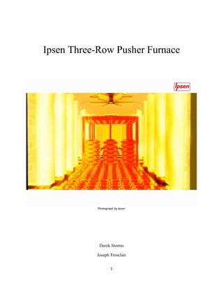
  • 1. Ipsen Three-Row Pusher Furnace Photograph by Ipsen Derek Storms Joseph Trosclair 1
  • 2. Mercedes-Benz was the first to acquire the Ipsen Three-Row Pusher Furnace at its powertrain plant in Mettingen, Germany, in autumn of 2013. This particular furnace is used for the thermal processing of multiple gearbox parts, crown wheels, and drive pinion wheels. Mercedes-Benz tasked Ipsen with building a thermal processing furnace in a limited space. Ipsen solved this dilemma by creating and delivering the special atmosphere three-row pusher system that Mercedes-Benz required.To do this, Ipsen carefully linked the high and low temperature furnaces, quenching equipment, cleaning *systems, and employed three rows in all of its main operating zones. This innovation allowed for flexibility for the different types of parts while minimizing needed space. This furnace is also beneficial to Mercedes-Benz becauseof its lower operating costs and higher efficiency. To understand how the Ipsen Three-Row Pusher Furnace is ideal for gearbox components, one must understand how pusher furnaces work. A pusher furnace is a continuous furnace that heat treats work-pieces by utilizing electric or hydraulic pushers positioned behind the charge. The charge is transferred through a sequence of one or more heating zones before it is discharged. Metallurgy and machine building use pusher furnaces to heat metal metal work- pieces or pressure shaping and can operate at wide temperature range (752°-2552°F). Using a pusher is the simplest way to move a charge through a furnace while using relatively simple equipment. The most common furnace to increase the hardness and case hardness is a pusher furnace, through carburizing or carbonitriding. Pusher furnaces can be used for the purposes of carburizing, ferritic nitrocarburizing, carbonitiriding, annealing, and stress relieving. This paper will focus on the gas carburizing aspect of a pusher furnace, as that is how Mercedes-Benz uses their three-row pusher furnace. 2
  • 3. Carburizing is an essential commercial heat treating process used to modify the surface chemistry of ferrous alloys. This is done through carbon diffusion and absorption in the gearbox components. The surface of the material will thus undergo a major change in its properties, which is froman increase in carbon content during the carburizing. The changes in its properties are due to the carburizing, creating a more porous and protective film of iron (III) oxide or manganese (II, III) oxide over the surface of the work-pieces. This will create a much stronger and more abrasive resistant superficial crystalline structure (0.13-0.75mm in thickness) while maintaining its tough and ductile base structure. This is especially important for gearbox components because they will become more resistant to abrasive wear, become harder, and will exhibit better fatigue properties. This process is crucial for any type of automotive drivetrain component because of the tremendous amounts of heat and friction that are generated during operation. This can be achieved though gas, liquid, or solid environment carburizing, although larger carburizing operations use gas. Gas carburizing is preferred because it is more accurate and has better reproducibility. For gas carburizing to be effective, the ferrous alloy must be heated and held at a temperature above its critical point for a period of time. To complete austenitization the work- pieces are put into a carbonaceous environment consisting of an endothermic carrier gas that is enriched with vaporized hydrocarbon liquid or hydrocarbon gas. The endothermic carrier gas is typically Nitrogen (N), carbon monoxide (CO), and propane (C4H10), methane (CH4), or hydrogen (H2). Vaporized methanol is sometimes used as the hydrocarbon source as well. The temperatures used for gas carburizing is usually 1562°-1742°F. At this temperature, the gaseous hydrocarbons will break down into CH4, CO2, CO, H20(g). The primary source of carbon will be CH4 while the CO2 will serve as a transport medium for the carbon. The purpose of the H2 and N2 3
  • 4. is to dilute the atmosphere inside the furnace. Pictured below are two examples of the austenite microstructure. Figure 1: Microstructure of Austenite An adequate carbon potential has to be sustained throughout the process to ensure absorption of carbon at the steel-atmosphere interface. CO and CO2 and H2 and H20 are used in proper balances to control the carbon potential, as well as the carburizing temperature and by the solubility of the carbon in the austenite. A carbon concentration gradient is formed between the surface and the interior of the steel as the carbon is absorbed into the steel. The carbon atoms then diffuse through an interstitial mechanism, down the composition gradient, according to Fick’s second law for diffusion, Equation 1: Fick’s 2nd Law for Diffusion. If the flux of carbon atoms from the endothermic gas at the steel atmosphere interface can be kept constant over time, more of the carbon atoms will be able to diffuse further into the surface of the work-pieces, creating a carburized case.This is how Ipsen is able to reliably reproduce their results. With their Lock Up technology, they are able to keep diffusion as close to steady 4
  • 5. state as possible.A carburized case will develop as the carbon atoms diffuse down the carbon gradient. The temperature and time at which the work-pieces are soaked will determine the depth of the case hardness.Pictured below is a graphical representation of Fick’s second law for diffusion. Figure 2: Pictured above is a graphical representationof carbon concentration level vs. depth beneath the surface ofthe material being treated. The x-axis can be considered the thickness of the work-piece being carburized. The y-axis is the level of concentration of endothermic gas on the surface of the steel. Overtime, the influx of carbon atoms being diffused into the work-piece will decrease due to the volume of carbon atoms per unit space increasing. The three-row pusher furnace from Ipsen used by Mercedes-Benzconsists of a pre- oxidation furnace, entry gate, three row heating zone, three-row carburizing furnace, single-row hardening zone, quenching, three-zone post-washing machine, tempering furnace, and transport units. First, the pre-oxidation chamber is preheated to 852°F using the EcoFire-Preheatsystem before a batch of components (loads) are loaded into this chamber. This chamber is a low 5
  • 6. oxygen, partial pressure chamber used to remove the non-porous chromium (III) oxide film that forms naturally in ambient temperatures on these metals. This non-porous compound can create a non-uniform distribution of carbon along the case surfaces.This leaves weak spots in the work- pieces, making the part unsalvageable for Mercedes-Benz. This allows the carburizing furnace to diffuse its more porous, iron based process gas into the work-pieces, allowing for uniform carburization throughout the work-pieces. Once this has been completed, the charges are transported via a pusher system into a waiting chamber that utilizes Ipsen’s patented Lock Up technology (Patent #8992213) . Thiscreates a gas-tight entry chamber so that minimal gas or heat can escape the carburizing furnace. Whenever a charge is ready to be pushed into the carburizing furnace, the pressure in the “waiting chamber” is increased. Following Gay-Lussac’s Law, , Equation 2: Pictured above, Gay Lussac's Law. as temperature increases, pressure also increases at linear rate. How this applies to carburizing is simple. The temperature in the carburizing furnace is heated to 1562°-1742F. This temperature, coupled with the endothermic gas, builds pressure because the atoms are getting increasingly excited as the temperature rises. This rise in pressure creates a force strong enough to allow the carbon atoms to break free from their gas bonds and ultimately diffuse into the work-piece.Once the entrance chamber is at an adequate temperature, the gas tight door will open and the charges will be pushed into the main furnace.This allows Ipsen’s furnace to regulate and maintain a steady temperature in the carburizing furnace as little heat, carbon and process gas are lost when transporting the charges in and out of the furnace.This conservation of heat, carbon and process 6
  • 7. gas will save money, speed the process, and improve efficiency. Pictured below shows how Ipsen’s Lock Up technology conserves heat. Figure 3: Pictured above is the difference in heat loss between the earlier furnace design, pictured on the left, and the new furnace design, pictured on the right. In conjunction with the carburizing furnace, Ipsen uses a patented system called Ecofire- Preheat (Patent #20130078152). The most notable attribute of the Ecofire systemis its cost savings. Typically, the standard procedure for disposing of exhausted process gas was to burn it off into the atmosphere. Ecofire reusesthe exhausted gas that is removed from the carburizing furnace and is then recycled with air to create a combustion gas.This combustion gas is then used with air in an open burner system to preheat the pre-oxidation furnace. For this to be done, the used process gas is transferred to an open burner system of the pre-oxidation furnace, adapted for endothermic gas. The gas, together with air, will then be burned off to heat up the load. During loading, unloading, and quenching, Ecofire is not used. The pre-oxidation furnace must then be heated by a normal open burner system. According to Ipsen, this can save an average of $20,948 7
  • 8. per year based on a three shift per day operation. Pictured below is a schematic diagram of showing how Eco-Fire Preheat works. Figure 4: Flow Diagram of the Ecofire Preheat system Upon exiting the carburizing furnace, the loads are then to be transferred to a single row pre-quench soak zone before being free quenched or press quenched. The pre-quench soak zone is essentially another waiting chamber with gas tight doors to allow the charge to air cool for a period before being loaded into the quenching zone. The recommended time is one hour for every inch of thickness. Once pre-quenching is done, the load is transferred into the quenching zone. The purpose of quenching is to rapidly cool the metal so that it transforms from austenite, which is a face centered cubic (FCC) structure, to martensite, a body centered cubic (BCC) structure, however, martensite is unstable in the quenched state. There are two types of quenching, free-quenching and press-quenching.Free quenching is the process in which an entire load is lowered into a vat of oil for rapid cooling.Press quenching involves holding the individual 8
  • 9. work-pieces under the controlled force of a quench die. The clamps that hold the piece are slotted to allow the quenching oil to flow through each slot, thereby cooling the part.The quench oils range in flash point from 270°-560°F. The operating temperature of the oil in an open quench tank should be at least 150°F below its flash point. Whether the part is to be free quenched or press quenched is determined by its size. Smaller parts will be free quenchedand theparts with diameters greater than 11.8 inches, such as ring gears, will be press quenched to keep them from distorting under rapid cooling. An automated transfer system will transport the parts for any other processing they may need after the quenching process is completed. If the work-pieces have not been distorted, the processing will include efficiently cleaning the parts in a three zone post washing machine before they are dried. If the parts have been distorted, they will be removed to be straightened or other related processes. After the post-quenching process has been completed, they are then sent to a two row tempering furnace. An automated transfer system will transport the parts for any other processing they may need after the quenching process is completed. If the parts are not distorted, they will be cleaned in a three zone washing station. Once cleaned, they are then sent to a two row tempering furnace. Tempering is done to develop the required combination of hardness, strength and toughness, or to relieve the brittleness of fully hardened steels.When tempered, excess carbon atoms diffuse back into the atmosphere and the martensite becomes pearlite. Pearlite combines the hardness and strength of cementite with the ductility of ferrite. The structure of pearlite is what gives the steel toughness. This is achieved by heating the work-pieces to a relatively low temperature (300°-1000°F) for a certain period of time to achieve the desired properties. Martensite is extremely hard but also very brittle in the as-quenched state, so it is unable to be 9
  • 10. used in most applications. Tempering is necessary to increase ductility, toughness, and relieve internal stresses that happen during the quenching process. The combination of quenching and tempering is important to make tough work-pieces. The result is a component with the appropriate combination of hardness, strength and toughness for the intended application. Tempering is also effective in relieving the stresses induced by quenching. The next process is cooling the parts in still air. The temperature of the air will determine the amount of hardness removed. The temperature of the air also depends on the composition of the alloy and the desired properties of the finished product. It is then that the parts will be sent to the load handling system for the final stages of cooling before being sent to storage. In conclusion, after having done the research on what we thought to be a not so interesting topic, the two of us now have a much better understanding of what kind of research goes into getting the best heat treatment possible for a low carbon steel. Carburizing can be defined to us as the positive correlation between temperature and pressure, allowing carbon atoms in a carbon bearing gas to attain enough energy from this increased heat and pressure forthe carbon atomto be able to break its bonds and “jump” into the steel. Over time more carbon will flow into the work-piece increasing the volume while maintaining a constant area.Quenching and tempering is also crucial to manufacturing carburized metal components that will be used in a dynamic setting. Quenching is a way to rapidly cool freshly carburized work-pieces, changing its microstructure from (FCC) to (BCC). Quenching also creates a lot of stresses inside the work-pieces due to the increased volume per unit area. This also creates a very brittle material. Tempering is done to relieve the stresses in the material and to allow excess carbon to sweat back into the atmosphere. This further changes the microstructure to a partial ferrite-cementite, otherwise known as Pearlite. 10
  • 11. Works Cited 1. "Partnering in Success, Ipsen Performs Challenging Installation for Mercedes- Benz." Partnering in Success, Ipsen Performs Challenging Installation for Mercedes- Benz. N.p., 4 Sept. 2014. Web. 13 Mar. 2015. 2. "Ipsen Delivers Three-Row Pusher Furnace." Ipsen Delivers Three-Row Pusher Furnace. N.p., n.d. Web. 13 May 2015. 3. "Pusher Furnace for Continuous Type Heat Treatment Application | Ipsen."Pusher Furnace for Continuous Type Heat Treatment Application | Ipsen. N.p., n.d. Web. 13 May 2015. 4. "Pusher Furnace." TheFreeDictionary.com. N.p., n.d. Web. 21 Mar. 2015. 5. "Sealing Mechanism for a Vacuum Heat Treating Furnace." Patent (Patent # 8,992,213 Issued March 31, 2015) - Justia Patents Database. N.p., n.d. Web. 21 May 2015. 6. "Device for Conditioning Process Gases for the Heat Treatment of Metallic Work Pieces in Industrial Furnaces." Patent Application (Application #20130078152 Issued March 28, 2013) - Justia Patents Database. N.p., n.d. Web. 21 Mar. 2015. 7. Matthias Rink, Dirk Joritz. “Increasing Energy Efficiency by Optimizing Furnace Design and Process Controll.” Ipsen (2014). PDF file. 11