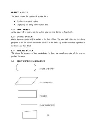
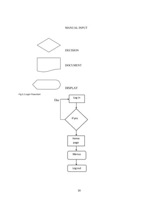
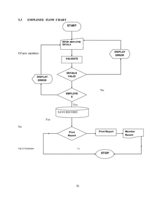
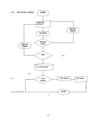
i
DECLARATION
STUDENT’S DECLARATION
As far as my knowledge and ability is concerned I declare that the work has been done to my
level best and it has not been presented for the award of Diploma at KCA university or any other
college or university.
Signature: ……………………………………..
Date: ……………………………………………
Name: ....................................................................
SUPERVISOR’S DECLARATION
This report has been submitted to KCA University for examinations with approval as the
university supervisor.
Signature: ……………………………………..
Date: ……………………………………………
Name: ………………………………………….
ii
DEDICATION
I’ve dedicated this project to my beloved family members. Also other special dedication goes to
my dear friends for their moral support during all this period.
iii
ACKNOWLEDGEMENT
The successful preparation and completion of this project marks a fundamental milestone in my
academic path. I feel humbled that God has accompanied me onthis journey and made all things
possible by giving strength, courage and power to believe in myself and pursue my dreams.
I highly appreciate and acknowledge the work done by my supervisor MR James Bwire who was
readily available to give assistance and guidance throughout my project report writing. However
my heartfelt appreciation goes to my uncle who granted me both moral and financial support to
enable me finish my course study. A great deal of gratitude must also be expressed to my
classmates for their undying motivation towards writing my report.
“May God bless and highly reward their efforts”
iv
ABSTRACT
The project intended to come up with an efficient and effective fleet management system
keepstrack the information about the Vehicles, Maintenance information Employees, Location
and Vendors. It also keeps track the maintenance performed for different vehicles which are used
for transportation.The super users of the system are the ‘ADMIN’ and the ‘MANAGERS’ of the
different departments allocated by the admin. The admin may be the owner of the transportation
organization or the manager of transportation department of the company. If any other vehicle is
added to the fleet which already exists for the organization/department the details of the vehicle
is added. Any employee is newly appointed or the existing employee is taken off both the details
are maintained including their personal details and profession details.The system has been
developed using database MYSQL as the backend, middle tier of PHP, HTML and CSS running
on WAMP SERVER.
v
TABLE OF CONTENTS
DECLARATION................................................................................................................................ i
DEDICATION.................................................................................................................................. ii
ACKNOWLEDGEMENT................................................................................................................. iii
ABSTRACT.....................................................................................................................................iv
CHAPTER ONE: INTRODUCTION...................................................................................................1
1.1 BACKGROUND OF THE PROJECT...................................................................................1
1.2 THE ORGANIZATIONAL STRUCTURE............................................................................2
1.3 PROBLEM STATEMENT...................................................................................................3
1.4 MAIN OBJECTIVE OF THEPROJECT...............................................................................3
1.5 JUSTICATION OF THE PROJECT .....................................................................................3
1.6 SCOPE OF THE PROJECT.................................................................................................4
CHAPTER TWO: LITERATURE REVIEW........................................................................................5
CHAPTER THREE: METHODOLOGY..............................................................................................7
3.1 SYSTEM DEVELOPMENT METHODOLOGY...................................................................7
3.2 DATA COLLECTION METHODS......................................................................................9
3.21 INTERVIEWS.................................................................................................................9
3.22 OBSERVATION .............................................................................................................9
CHAPTER FOUR: SYSTEM REQUIREMENTS...............................................................................10
4.1 FUNCTIONAL REQUIREMENTS....................................................................................10
4.2 NONFUNCTIONAL REQUIREMENTS............................................................................10
4.3 PERFORMANCE REQUIREMENTS.................................................................................10
4.4 HARDWARE REQUIREMENTS......................................................................................10
4.5 SOFTWARE REQUIREMENTS........................................................................................10
CHAPTER FIVE:DESIGN ...............................................................................................................12
5.1 SYSTEM MODULE DESIGN...........................................................................................12
5.12 AUTHENTICATION.....................................................................................................12
5.13 MENU...........................................................................................................................12
5.14 INPUT DESIGN ............................................................................................................13
5.15 OUTPUT DESIGN.........................................................................................................13
vi
5.16 PROCESS DESIGN.......................................................................................................13
FLOW CHART SYMBOLS USED ...............................................................................................13
EMPLOYEE FLOW CHART..........................................................................................................15
BUS FLOW CHART.......................................................................................................................16
CHAPTER SIX: TESTING..............................................................................................................21
7.1 TYPES OF ERRORS FIXED DURING TESTING..............................................................21
7.2 MAINTENANCE..............................................................................................................21
7.3 REPLACEMENT..............................................................................................................22
CHAPTER SIX: IMPLEMENTATION .............................................................................................23
6.0 IMPLEMENTATION..............................................................................................................23
Test plan ......................................................................................................................................23
Unit testing ...............................................................................................................................23
CHAPTER EIGHT: CONCLUSION AND RECOMMENDATION ....................................................25
8.1 ACHIEVEMENTS..................................................................................................................25
8.2 CHALLENGES......................................................................................................................26
8.3APPENDICES.........................................................................................................................27
APPENDIX A...........................................................................................................................27
LIST OF REFERENCE....................................................................................................................27
APPENDIX B: PROJECT SHEDULE........................................................................................28
GANTT CHART..........................................................................................................................28
LIST OF FIGURES
Fig 1.1 Organization Structure ............................................................................................................2
Fig 3.1 Waterfall Mode .......................................................................................................................7
Fig 5.1 Login Flowchart .....................................................................................................................14
Fig 5.2 Employee …………….................................................................................................................15
Fig 5.3 Bus Flow Chart ......................................................................................................................16
vii
Fig 5.4 Login Form............................................................................................................................17
Fig 5.5 Homepage ............................................................................................................................18
Fig 5.6 Employee Records .................................................................................................................18
Fig 5.7 Adding anew bus ...................................................................................................................19
Fig 5.8 Logging History .....................................................................................................................20
Fig 5.9 Logging Out ..........................................................................................................................20
Fig 8.1 Gantt Chart ...........................................................................................................................28
1
CHAPTER ONE:INTRODUCTION
The fleet operation industry has been an area of heavy investment since independence and the progress
has been significant. But the task is so gigantic that it requires many years and large doses of investment
to bring about the desired improvement in the country’s transportation system. However, the sector has
not been able to keep pace with the rising demand in fleet management services and is proving a drag in
the economy. Kenya’s transport sector being large and diverse caters for millions of people, due to its
high growing economy it has witnessed a rise in demand for infrastructure and services for around 10%
a year. Major improvements are therefore required to support the growth of the economy.
This project intended to investigate this unexplored area. This was done by evaluating the fleet planning
and management systems problems experienced by various Kenyan companies running large fleet of
vehicles. This application of information technology to vehicle fleet management was centered on
tracking vehicles information, driver monitoring and fleet security control. Fleet management system
aims at improving the quality and efficiency of the industry by keeping track of vehicles information
alongside the employee information.
Any employee is newly appointed or the existing employee is taken off both the details are maintained
including their personal details and profession detail Since all the mentioned functionalities above
cannot be achieved in the existing, therefore there is need for a better system that will keep track of all
this information to improve on the company’s future development. By doing so, this will make the
process simple easier to schedule vehicles as well as staff.
Fleet management system being an umbrella for applications that aim improving the overall
performance, maintenance, repair and employee follow up there is need for it to be developed. Through
the information that will be gathered via literature, observation and interviews it will be able to come up
with an efficient system.
1.1 BACKGROUND OF THE PROJECT
In both public and private transport sectors in our country, we’ve got different systems in various
companies which enhance their daily operations respectively. Crown Bus Company Ltd has been a
reputable transport company that provides better transport services to its customers so as to achieve its
mission and vision which revolves around; comfort, reliability, outstanding, welcoming and nostalgic
experience. It started its operations in 2006 out of passion transport upon realization that most bus
companies did no focus on passenger comfort and were slow to react to customer demands.
The project was based on the background of Crown Bus Company that started its operations in 2006 out
of the passion for passenger transport upon realization that most companies did not focus on passenger
comfort and were slow to react to customer demands. Its management structure is made up of two
directors who act as the shareholders of the company. The directors from inception were focused on
service delivery to its customers. Under this there are various employees who work in order to ensure
equal delivery to its customers. The mission of crown Bus Company was to revolutionize the transport
sector by introducing executive buses and acquiring a new state of art luxury.
2
It was also the first bus company to provide bottled mineral water to its customers, introduce executive
buses in the western region rated number one in the bus category by Association of Kenya Insurance.
The company has also automated its offices to accommodate online booking and payments however the
current system cannot automate the vehicles information, repair and maintenance alongside the
employee details. The company has two directors that operate with the aim of improving and achieving
the company’s service delivery. The company has also automated its offices to accommodate online
booking and payments however; the current system doesn’t keep track of vehicle s information
alongside employees. Since the system cannot automate huge fleet information this has resulted to
inefficiency, poor interactivity and higher expenses in managing the fleet.
Considering the facts, this project introduced the use of latest systems and open source tools to build a
low cost fleet management system for crown bus that will address the problems discussed. This will
have a greater impact on the company’s future development upon ensuring service delivery.
1.2 THE ORGANIZATIONAL STRUCTURE
The following diagram shows the organizational structure of crown bus company.
Fig 1.1 Organization Structure
BOARD OF DIRECTOR
GENERAL MANAGER
ADMINCLERK
DRIVERSMECHANICSGENERAL
CLERKS
ACCOUNT
CLERKS
ACCOUNTANT MAINTENANCE
SUPERVISOR
DRIVER
SUPERVISOR
MARKETING
REPRESENTATIVES
OPERATION
MANAGER
ASSISTANTGENERAL
MANAGER/HR
3
1.3 PROBLEM STATEMENT
Most bus companies running nowadays with huge fleet of vehicles haven’t acquired the state of art when
it comes to managing vehicles information, Crown Bus Company being among them started its
operations in 2006 it has been not been able to keep track of its vehicles information and staff together
since vehicles can be allocated to any driver provided there is need for delivery.
• Having huge fleet information that becomes hard to manage.
• In order to schedule vehicles as well as staff, we the scheduler should not how many vehicles are
there on board and available for allocation.
• Keeping track of repair information is difficult as some times vehicles can be referred for
insurance
• Errors of omission deliberate and non-deliberate since there is no update of information
1.4 MAIN OBJECTIVE OF THE PROJECT
The goal of any system development is to develop and implement system cost effectively; user friendly
and most suited to the users is to the heart of the process. Analysis is the study of various operations
performed by the system and their relationship within and outside the system. The main objective of the
project was to;
i. Develop an efficient and effective fleet management system that implements the proposed
solution in a user friendly manner.
ii. To create a fleet management system that will automate of vehicles information alongside the
staff
iii. To create a fleet management system that will manage huge fleet information in a computerized
and efficient manner
iv. To generate reports on fleet general information and employee records.
v. To provide best services to their customer, increasing working capacity, accuracy in calculation,
better maintenance of the organization resources
1.5 JUSTICATION OF THE PROJECT
The major reasons why I had to spend time doing this project were to:
 Come up with an efficient, effective system that will enable the company to keep track of
vehicles information, repair, and maintenance and employee information.
 Meet the requirements for Diploma in information technology
 Manage my time well in order to meet the required deadlines.
 Improve my programming skills and be able to apply them in the real world
 Understand other languages that are were not inline to the syllabus but may be required in
developing my project.
4
1.6 SCOPE OF THE PROJECT
The system is based to manage fleet information that take place within Crown Bus Company only.
However this should not interfere with the company’s operations done from other departments.
5
CHAPTER TWO: LITERATURE REVIEW
Researchers have tested a wide array of technologies in attempt to find improved methods of monitoring
transport conditions. This research in fleet surveillance has ranged from studies of traditional loop
detection methods to the use of anti –submarine warfare. A brief survey of technologies explored during
the recent past has been given below to provide an understanding of the level of research interest in fleet
management systems.
According to the European Commission DG (Energy, 2009)some software information systems can
improve both mobility and transportation management fleet being one of them. A number of
applications (Waiyaki E. , dissertation_waiyaki_ec.pdf?, 2013)(e.g. web- enabled information and
booking services, delivery notification and information through mobile telephones, trip planning and
resource optimization, GPS- based vehicle location systems, long range, wireless communication and
others) enable users to manage resources and realize flexibility in demand.
In today’s competitive marketplace, it is imperative that businesses operate at peak efficiency, provide
timely customer service and still make a profit. Thus, in view of these realities, it is often crucial for
business owners to discover those areas in terms of which cost effectiveness may be improved.
(Azevedo, 2007)support the idea that ICT systems affect competition in the logistics sector in three
distinct ways. Firstly, ICT systems may change the structure of the logistics industry, and even modify
the rules of competition. Technology is usually the driving force behind such discoveries. Organizations
that manage fleets or a mobile sales force as well as field service organizations are facing many
challenges. These challenges include improving compliance and organizational communications,
reducing costs, and improving customer satisfaction. As a result, fleet management systems are
perceived in terms of how they are able to benefit companies by realizing efficiency and profitability. In
the knowledge-based economy of today, the rapidly changing and uncertain environment means that
transport firms are facing their biggest challenge in how to address the current situation and capture a
competitive advantage. The increasing competence in the market is an important factor that drives the
adoption of new technologies and innovation, as companies search for new opportunities to cut costs by
improving process efficiency or by developing new products (Hidalgo.A. & Lopez, 2013)
Current real-time fleet management systems may be categorized according to the type of real-time
information which they process. Available work addresses cases where a new customer request appears
and must be fulfilled in a specific time period. The systems that existed in the previous decade were able
to cope with new customer requests although they either assumed that travel times were constant
throughout the day or they used simple procedures to adjust such travel times, including multiplier
factors that were associated with different periods of the day. However, these assumptions were weak
approximations of the real-world conditions in which travel times are subject to more subtle variations
over time (Goetschalckx, 2007), (Powell, 2004) (Savelsbergh, 1998) (Ganz, 2005)These variations may
result either from predictable events such as congestion during peak hours or from unpredictable events
such as accidents, mechanical failures, and so forth.
6
The objective of this research is to align operational and mobile information system models in a manner
that will meet the demands of transport companies. In addition, road transport logistics exceeds other
modes such as sea (41%), rail (8%), inland waterways (4%) and pipeline (3%) (Mondragon Coronado,
2009)The implementation of fleet management system incorporates several value-added processes
including delivery controls such as updated, estimated time of arrival (ETA) and the issue of late
running; statistical reporting such as vehicle and job histories; digital imaging for damaged goods;
vehicle defect reporting; driver time reporting; and highways agency data/warnings.
A recent survey of the users of tracking systems, published in (Porter, 2008)reported benefits such as
increased productivity, reduced costs and enhanced fleet performance. Other benefits mentioned include
reductions in overtime claims, insurance premiums, fuel usage, communications costs and
administration.(Roseindia, 2012)(http://www.roseindia.net/technology/gps/fleetmanagement.
Fleet management system helps the manager to keep the record of vehicles in the fleet or profile of the
driver. These records can be of great use when it comes to references, bills and sometimes to save
themselves from the lawsuits. Keeping the driver profile helps manager to know about his behavior on
and off the work, this can come crucial at any time.
Finally the validity of this proposed system will of management will be examined through its different
applications to organizational improvement.
Limitations of the existing system
• Keeping track of repair information is difficult as some times vehicles can be referred for
insurance
• In order to schedule vehicles as well as staff, we the scheduler should not how many vehicles are
there on board and available for allocation.
7
CHAPTER THREE: METHODOLOGY
This chapter describes the methodology used in conducting the project. These includes; data collection
methods, data collection instruments, reliability of collection instruments, validity of collection
instruments and data analysis benefits and limitations
3.1 SYSTEM DEVELOPMENT METHODOLOGY
For the purpose of this project I used the Waterfall model. Briefly, this model known as thewaterfall is
an approach to development that emphasizes completing a phase of the development before proceeding
to the next phase. In conjunction with certain phase completions, a baseline is established that "freezes"
the products of the development at that point. If a need is identified to change these products, a formal
change process is followed to make the change. The graphic representation of these phases in software
development resembles the downward flow of a waterfall.
The following diagram shows the waterfall model.
Fig 3.1 Waterfall Model
Source(Tutorialspoint, 2010)http://www.tutorialspoint.com/sdlc/sdlc_waterfall_model.htm
8
The sequential phases in Waterfall model are:
 Requirement Gathering and analysis: All possible requirements of the system to be developed
are captured in this phase and documented in a requirement specification doc.
 System Design: The requirement specifications from first phase are studied in this phase and
system design is prepared. System Design helps in specifying hardware and system requirements
and also helps in defining overall system architecture.
 Implementation: With inputs from system design, the system is first developed in small
programs called units, which are integrated in the next phase. Each unit is developed and tested
for its functionality which is referred to as Unit Testing.
 Integration and Testing: All the units developed in the implementation phase are integrated
into a system after testing of each unit. Post integration the entire system is tested for any faults
and failures.
 Deployment of system: Once the functional and non-functional testing is done, the product is
deployed in the customer environment or released into the market.
 Maintenance: There are some issues which come up in the client environment. To fix those
issues patches are released. Also to enhance the product some better versions are released.
Maintenance is done to deliver these changes in the customer environment.
All these phases are cascaded to each other in which progress is seen as flowing steadily downwards
(like a waterfall) through the phases. The next phase is started only after the defined
ADVANTAGES OF WATERFALL MODEL
 Simple and easy to understand and use
 Easy to manage due to the rigidity of the model. Each phase has specific deliverables and a
review process.
 Phases are processed and completed one at a time.
 Works well for smaller projects where requirements are very well understood.
 Clearly defined stages.
 Well understood milestones.
 Easy to arrange tasks.
 Process and results are well documented
DISADVATAGES
 No working software is produced until late during the life cycle.
 High amounts of risk and uncertainty.
 Not a good model for complex and object-oriented projects.
9
3.2 DATA COLLECTION METHODS
These are the methods that I used in gathering data.
3.21 INTERVIEWS
This refers to face to face/ conversational between the system analyst and the user. The analyst obtains
answers to questions that he or she asks. I preferred using this because of the following.
 Information collected through this method was reliable and accurate since people who were
affected by the current system were the one interviewed
 Verbal communication for each and every interviewee was observed as well as body language.
 It gave out the opportunity to motivate interviewees to respond freely and open to question.
 Helps to overcome fears and resistance to change what may be felt by employees and gain their
trust
Disadvantages of this method
 Success of the interview is highly dependent on the system analyst
 It requires a lot of time
 Interviewees may feel that they are being summoned by the interviewer and may fail to give
correct information.
3.22 OBSERVATION
It is a data gathering technique whereby the system analyst observes the behaviors of respondents. It is
the most effective fact finding technique that requires analyst to participate in performing some of the
activities carried out by the user.
Advantages
• Data gathered is highly reliable thus the method can be used to verify the facts collected through
other methods.
• The analyst is able to see what is done clearly including facts which are difficult to explain in
writing.
• Inaccurately described work can easily be identified
• Is relatively cheap compared to other methods
Disadvantages
• People feel uncomfortable being observed and they behave abnormally and influences the
analyst conclusion
• The task being observed may be interrupted and the analyst may gather wrong facts
10
CHAPTER FOUR:SYSTEM REQUIREMENTS
4.1 FUNCTIONAL REQUIREMENTS
These are the fundamental actions that the system must perform. The system should be able to carry out
the following.
 Vehicle information management i.e. adds, delete or edit vehicle details.
 Display login history.
 Employee information management i.e. adds, delete and modify employee details
4.2 NONFUNCTIONAL REQUIREMENTS
Nonfunctional requirements define the needs in terms of performance, logical database requirements,
design constraints, standards compliance, reliability, availability, security, maintainability, and as well
as portability i.e.
 The system should have an easy user interface to provide learn ability to its user.
 The system should not take much time during login
4.3 PERFORMANCE REQUIREMENTS
Requirement specification plays an important part in the analysis of a system. Only when the
requirement specifications are properly given, it is possible to design a system, which will fit into
required environment. The existing system is completely dependent on the user to perform all the duties.
The requirement specification for any system can be broadly stated as given below:
· The system should be able to interface with the existing system
· The system should be accurate
· The system should be better than the existing system
4.4 HARDWARE REQUIREMENTS
 Hard disk- Minimum 20GB 40GB recommended
 Processor- 1.0GHZ
 Ram-1Gb minimum
4.5 SOFTWARE REQUIREMENTS
 Operating system- windows XP service pack 3and above
 Technologies-Apache wamp server, Dreamweaver 8.0
 Browser- Internet Explorer or Mozilla Firefox
11
4.6 SYSTEM OVERVIEW
Generally the system has to do the following functionalities.
i. Manage employee records successful.
ii. Password to enhance security.
iii. Manage bus records.
iv. Generating reports.
v. Show login history
12
CHAPTER FIVE:DESIGN
PHP, HTML, JAVASCRIPT and MYSQL were used to write the program (codes) required for
this system. PHP was also used to develop the front end application that interface between the
user and the system while MYSQL acted at the background.
5.1 SYSTEM MODULE DESIGN
The system design modules are as follows
 Authentication
 Main menu
 Output
 Input
5.12 AUTHENTICATION
The program form window namely login will be responsible for authorized user to access the
system. It has been designed in user or user name and the corresponding password for the user or
authorized guest. If both user name and password are correct then the user will be authorized to
access the system, otherwise the user will be denied with message. “Please Check Your
username and Password.”
5.13 MENU
There will be a number of menus in the fleet management system that will be guiding the user to
navigate through the system. The menu will enable the user to choose the execution that he
would like the system to perform by simply choosing on the different menu option on the main
interface.
INPUT MODULE
This will enable the user of the system to: -
 Edit existing records
 Input new records
 Saving of changes
 Exit from the system.
13
OUTPUT MODULE
The output outside the system will be used for: -
 Printing the required reports.
 Displaying and listing all the system data.
5.14 INPUT DESIGN
All the input will be entered into the system using an input device, keyboard only.
5.15 OUTPUT DESIGN
Output from the system will be mainly in the form of lists. The user shall either run the existing
programs to list the desired information or click on the menu e.g. to view members registered in
the library and their details
5.16 PROCESS DESIGN
This shows the sequence of data manipulation. It shows the actual processing of the input to
produce the output.
5.2 FLOW CHART SYMBOLS USED
START AND END
INPUT / OUTPUT
PROCESS
FLOW DIRECTION
14
MANUAL INPUT
DECISION
DOCUMENT
DISPLAY
Fig 5.1 Login Flowchart
Else
If yes
Log in
Home
page
Log out
Menus
15
5.3 EMPLOYEE FLOW CHART
Of new members
No
Yes
Yes
No
Fig 5.2 Employee Yes
START
ENTER EMPLOYEE
DETAILS
VALIDATE
DISPLAY
ERROR
DETAILS
VALIDDISPLAY
ERROR
EMPLOYE
E
Existing
Print
Report
Print Report
STOP
Member
Report
SAVE RECORD
16
5.4 BUS FLOW CHART
No
Yes
Yes
No
Fig 5.3 Bus Flow Chart
Yes
START
ENTER BUS
DETAILS
VALIDATE
DISPLAY
ERROR
DETAILS
VALIDDISPLAY
ERROR
BUS
Existing
Print
Report
SAVE RECORD
Print Report
STOP
Bus report
SAVE RECORD
17
PHYSICAL AND LOGICAL DESIGN
LOGIN FORM
This form allows the user to log into the system.
Fig 5.4 Login Form
18
HOMEPAGEFig 5.5 Homepage
EMPLOYEE RECORDSFig 5.6 Employee Records
19
ADDING ANEW BUS
Fig 5.7 Adding a new bus
20
LOGIN HISTORY
Shows the login history from the start of the system.
Fig 5.8 Logging History
LOGGING OUT
Fig 5.9 Logging Out
21
CHAPTER SIX: TESTING
In this stage, both individual components and the integrated whole have been methodically
verified to ensure that they are error-free and fully meet the requirements outlined in the first
step.
 Unit testing of individual code modules
 System testing of the integrated product
 Acceptance testing
This formally, was conducted by or on behalf of the customer. Defects, if found, are logged and
feedback provided to the implementation team to enable correction. This is also the stage at
which product documentation, such as a user manual, is prepared, reviewed and published. Once
the product has been tested and certified as fit for use, and involves preparing the system or
product for installation and use at the customer site. Delivery may take place via the Internet or
physical media, and the deliverable is typically tagged with a formal revision number to facilitate
updates at a later date.
6.1 TYPES OF ERRORS FIXED DURING TESTING.
a) Bugs
These were faults in software. On finding these errors, Debugging was done where errors were
located and fixed whenever the software did not behave correctly.
b) Syntax errors
These errors are made due to wrong definition or non-invalid use of a programming
c) Logicalerrors
These are errors in programming logic they result in incorrect results.
6.2 MAINTENANCE
This step occurs after installation, and involves making modifications to the system or an
individual component to alter attributes or improve performance. These modifications arise
either due to change requests initiated by the customer, or defects uncovered during live use of
the system. Typically, every change made to the product during the maintenance cycle is
recorded and a new product release (called a "maintenance release" and exhibiting an updated
revision number) is performed to enable the customer to gain the benefit of the update.
22
6.3 REPLACEMENT
Direct changeover/ Straight change over
Takes a lot of planning however the best because it is simple is. All files have to be ready to
load; all workers need to have been trained in advance and the system must have been properly
tested. If the check outs do not work, when they are switched on, the store will have to close
because they cannot go back to the old system.
Advantages
i. Fast implementation
ii. It’s cheaper than parallel since the new system is run only at that particular time
hence the old system is abandoned.
Disadvantages
i. Any new data files have to be operational before the change
23
CHAPTER SEVEN: IMPLEMENTATION
6.0 IMPLEMENTATION
This fleet management system’s user interface was implemented using PHP and HTML while
the Database was implemented using MYSQL. It functions as storage to keep track of the entire
bus records and employee records.
a) PHP-It was used to query data from the database and enable some automation using
logical conditions.
b) JavaScript–it enabled the validation of forms used in the entire project.
c) HTML-Enabled the development of a web based interface that can be interpreted by
other browsers.
d) CSS-Enabled organization and consistency of the appearance of the webpage.
Test plan
Fleet management system was thoroughly tested with the administrator and user so as to make
sure that the final system does not have defects. There exist four major types of testing. They
include;
Unit testing
In this type of testing, the smallest parts of the system I.e. units were individually tested and
independently examined for correct functionality. This type of testing involved both the positive
testing and negative testing.
Integration testing
This is where two or more related programs were tested. The test involved two types of approaches i.e.
the bottom-up approach that begins with the simplest task to the most complex part e.g. from bus table to
the database and up-down approach that tests the system from the complex task to the simplest unit of all.
All the files linked to the database through the data environment wereconnected well without any
issue.
24
System testing
This is the type of testing where I tested the entire system for functionality to ensure that the
system can process and handle large volumes of data quickly and efficiently. Possible problems
were corrected before really conversion.
25
CHAPTER EIGHT: CONCLUSION AND RECOMMENDATION
It has been a great pleasure for me to work on this exciting and challenging project. This
project proved good for me as it provided practical knowledge of not only programming in
PHP,JAVASCRIPT and HTML based application, but also about all handling procedure related
with “CROWN BUS COMPANY”. It also provided knowledge about the latest technology
used in developing web based system that will be of great demand in future. This will provide
better opportunities and guidance in future in developing projects independently.
8.1 ACHIEVEMENTS.
The successive completion of this project is a clear indication that the following were
achieved.
 The system can store employee records successfully.
 The system has improved system security features for authentication i.e. login
password.
 The system is able to keep bus records.
 The system has measures that control errors including: submitting an empty or
incomplete form.
 The system provides login history to show time the user was on the system.
 The system is able to print view the bus and employee records.
8.2 WHAT I LEARNT
 I have gainedskillsinprogramminglanguages PHP, JAVASCRIPTand HTML.
 I havelearnttheuseofdifferentjoinsinMySQL queries.
 I have gainedmoreskillsinvalidationoffieldinforms andtables.
 I havealsogainedmoreexperienceinwritingofproposals and technical reports.
 I haveacquiredskillsinindependentprojectplanningandscheduling.
 The project has also enabled me to fulfill the requirement for the award of Diploma in
Information technology.
26
8.3 CHALLENGES
During the development of theproject, there were various challenges that were noted.
i. Financial constraints in acquiring the right resources
ii. Limited knowledge in some of the tools used i.e. PHP, MySQL and Apache WAMP
server.
iii. More time spent on proposal writing thus affecting the project schedule.
iv. Doing the project for the first time was abit challenging.
v. Undertaking the project at the same time attending other units in class.
vi. Insufficient knowledge in use of project planning software i.e. MS Project.
vii. Unable to achieve all the functionalities of the system i.e. maintenance, tracking and
repair modules.
8.4 RECOMMENDATIONS
In overcoming the challenges above I do recommend that:
i. The project has not captured all the functionalities that had to be rendered i.e.
maintenance, repair and tracking modules, therefore the project is open for future
improvement.
ii. I recommend the incorporation of tracking and employee monitoring in the system to
enhance more security and flexibility.
iii. I would recommend that the system developer wishing to implement this should use
higher level languages like JAVA which is currently in the curriculum.
iv. I recommend use of interviews and observations for the developer wishing to implement
this.
v. I recommend that the institution should set project proposal to be completed at level four
of Diploma so as to set time for project development and documentation.
vi. The institution should support students in printing out project documentation by
providing printing equipments in Oder to reduce project budget.
vii. The institution to provide an open forum where students can propose project ideas prior
the actual stage of project development.
viii. The institution to provide proprietary software’s for students doing projects.
27
8.3APPENDICES
APPENDIX A
LIST OF REFERENCE
Azevedo, S. F. (2007). The role of Informational and Communication technologies In promoting
Competitive advantages of the firm. Munich: University Library Of Munich.
Energy, E. C. (2009). Transport Research Knowledge Center. New York: Freight Transport
Thematic.
Ganz, N. R. (2005). Dynamic Vehicle Dispatching . Operations Research, 47(5).
George Marakas, M. (2001). System Analysis And Design. Prentice Hall.
Goetschalckx, M. (2007). International Journal Of Physical Distribution And Materials
Management , 34-32.
Hidalgo.A. & Lopez, 2. (2013, September 13). Drivers And Impact of ICT on transport And
logistics. Retrieved July 23, 2014, from unisa.ac:
http://uir.unisa.ac.za/bitstream/handle/10500/11883/dissertation_waiyaki_ec.pdf?sequence=1
Mondragon Coronado, A. L. (2009, May ). mondragon. Retrieved June 10, 2014, from
mondragon_corporation.com.
Porter. (2008, April ). M logman. Retrieved July 14, 2014, from M logman Website :
http://www.mlogmag.com/magazine/34/A of_fleets.shtml.
Powell, W. (2004). Real Time Optimization For Truckload Motor Carriers. Ms Today Vol 1.
Roseindia. (2012, April). Fleet Management. Retrieved June 24, 2014, from roseindia.net:
http://www.roseindia.net/technology/gps/fleetmanagement .
Savelsbergh, M. &. (1998). Dynamic Routing Of Independent Vehicles . Operations Research,
vol 46:474-490.
Tutorials Point. (2014, January). Retrieved July 18, 2014, from tutorialspoint.com:
http://www.tutorialspoint.com/sdlc/sdlc_waterfall_model.htm
Waiyaki, C. (2008). Fleet Solutions. M.logistics .
Waiyaki, E. (2013, September 13). dissertation_waiyaki_ec.pdf? Retrieved June 14, 2014, from
Leverage Technology For Business :
http://uir.unisa.ac.za/bitstream/handle/10500/11883/dissertation_waiyaki_ec.pdf?sequence=1
Waiyaki, E. (2003). Telematics Good Practice Guide :341. London: Stationery Office.
28
APPENDIX B
APPENDIX B: PROJECT SHEDULE
This schedule shows how much time I took in doing the project. In my proposal I had
proposed that the project will be completed in 10 weeks but it took me 2 more weeks since I
had to complete my final exams before finishing the project. Below is the new Gantt chart
that I used.
GANTT CHART
Fig 8.1 Gantt Chart

Report Writing

  • 1.
    i DECLARATION STUDENT’S DECLARATION As faras my knowledge and ability is concerned I declare that the work has been done to my level best and it has not been presented for the award of Diploma at KCA university or any other college or university. Signature: …………………………………….. Date: …………………………………………… Name: .................................................................... SUPERVISOR’S DECLARATION This report has been submitted to KCA University for examinations with approval as the university supervisor. Signature: …………………………………….. Date: …………………………………………… Name: ………………………………………….
  • 2.
    ii DEDICATION I’ve dedicated thisproject to my beloved family members. Also other special dedication goes to my dear friends for their moral support during all this period.
  • 3.
    iii ACKNOWLEDGEMENT The successful preparationand completion of this project marks a fundamental milestone in my academic path. I feel humbled that God has accompanied me onthis journey and made all things possible by giving strength, courage and power to believe in myself and pursue my dreams. I highly appreciate and acknowledge the work done by my supervisor MR James Bwire who was readily available to give assistance and guidance throughout my project report writing. However my heartfelt appreciation goes to my uncle who granted me both moral and financial support to enable me finish my course study. A great deal of gratitude must also be expressed to my classmates for their undying motivation towards writing my report. “May God bless and highly reward their efforts”
  • 4.
    iv ABSTRACT The project intendedto come up with an efficient and effective fleet management system keepstrack the information about the Vehicles, Maintenance information Employees, Location and Vendors. It also keeps track the maintenance performed for different vehicles which are used for transportation.The super users of the system are the ‘ADMIN’ and the ‘MANAGERS’ of the different departments allocated by the admin. The admin may be the owner of the transportation organization or the manager of transportation department of the company. If any other vehicle is added to the fleet which already exists for the organization/department the details of the vehicle is added. Any employee is newly appointed or the existing employee is taken off both the details are maintained including their personal details and profession details.The system has been developed using database MYSQL as the backend, middle tier of PHP, HTML and CSS running on WAMP SERVER.
  • 5.
    v TABLE OF CONTENTS DECLARATION................................................................................................................................i DEDICATION.................................................................................................................................. ii ACKNOWLEDGEMENT................................................................................................................. iii ABSTRACT.....................................................................................................................................iv CHAPTER ONE: INTRODUCTION...................................................................................................1 1.1 BACKGROUND OF THE PROJECT...................................................................................1 1.2 THE ORGANIZATIONAL STRUCTURE............................................................................2 1.3 PROBLEM STATEMENT...................................................................................................3 1.4 MAIN OBJECTIVE OF THEPROJECT...............................................................................3 1.5 JUSTICATION OF THE PROJECT .....................................................................................3 1.6 SCOPE OF THE PROJECT.................................................................................................4 CHAPTER TWO: LITERATURE REVIEW........................................................................................5 CHAPTER THREE: METHODOLOGY..............................................................................................7 3.1 SYSTEM DEVELOPMENT METHODOLOGY...................................................................7 3.2 DATA COLLECTION METHODS......................................................................................9 3.21 INTERVIEWS.................................................................................................................9 3.22 OBSERVATION .............................................................................................................9 CHAPTER FOUR: SYSTEM REQUIREMENTS...............................................................................10 4.1 FUNCTIONAL REQUIREMENTS....................................................................................10 4.2 NONFUNCTIONAL REQUIREMENTS............................................................................10 4.3 PERFORMANCE REQUIREMENTS.................................................................................10 4.4 HARDWARE REQUIREMENTS......................................................................................10 4.5 SOFTWARE REQUIREMENTS........................................................................................10 CHAPTER FIVE:DESIGN ...............................................................................................................12 5.1 SYSTEM MODULE DESIGN...........................................................................................12 5.12 AUTHENTICATION.....................................................................................................12 5.13 MENU...........................................................................................................................12 5.14 INPUT DESIGN ............................................................................................................13 5.15 OUTPUT DESIGN.........................................................................................................13
  • 6.
    vi 5.16 PROCESS DESIGN.......................................................................................................13 FLOWCHART SYMBOLS USED ...............................................................................................13 EMPLOYEE FLOW CHART..........................................................................................................15 BUS FLOW CHART.......................................................................................................................16 CHAPTER SIX: TESTING..............................................................................................................21 7.1 TYPES OF ERRORS FIXED DURING TESTING..............................................................21 7.2 MAINTENANCE..............................................................................................................21 7.3 REPLACEMENT..............................................................................................................22 CHAPTER SIX: IMPLEMENTATION .............................................................................................23 6.0 IMPLEMENTATION..............................................................................................................23 Test plan ......................................................................................................................................23 Unit testing ...............................................................................................................................23 CHAPTER EIGHT: CONCLUSION AND RECOMMENDATION ....................................................25 8.1 ACHIEVEMENTS..................................................................................................................25 8.2 CHALLENGES......................................................................................................................26 8.3APPENDICES.........................................................................................................................27 APPENDIX A...........................................................................................................................27 LIST OF REFERENCE....................................................................................................................27 APPENDIX B: PROJECT SHEDULE........................................................................................28 GANTT CHART..........................................................................................................................28 LIST OF FIGURES Fig 1.1 Organization Structure ............................................................................................................2 Fig 3.1 Waterfall Mode .......................................................................................................................7 Fig 5.1 Login Flowchart .....................................................................................................................14 Fig 5.2 Employee …………….................................................................................................................15 Fig 5.3 Bus Flow Chart ......................................................................................................................16
  • 7.
    vii Fig 5.4 LoginForm............................................................................................................................17 Fig 5.5 Homepage ............................................................................................................................18 Fig 5.6 Employee Records .................................................................................................................18 Fig 5.7 Adding anew bus ...................................................................................................................19 Fig 5.8 Logging History .....................................................................................................................20 Fig 5.9 Logging Out ..........................................................................................................................20 Fig 8.1 Gantt Chart ...........................................................................................................................28
  • 8.
    1 CHAPTER ONE:INTRODUCTION The fleetoperation industry has been an area of heavy investment since independence and the progress has been significant. But the task is so gigantic that it requires many years and large doses of investment to bring about the desired improvement in the country’s transportation system. However, the sector has not been able to keep pace with the rising demand in fleet management services and is proving a drag in the economy. Kenya’s transport sector being large and diverse caters for millions of people, due to its high growing economy it has witnessed a rise in demand for infrastructure and services for around 10% a year. Major improvements are therefore required to support the growth of the economy. This project intended to investigate this unexplored area. This was done by evaluating the fleet planning and management systems problems experienced by various Kenyan companies running large fleet of vehicles. This application of information technology to vehicle fleet management was centered on tracking vehicles information, driver monitoring and fleet security control. Fleet management system aims at improving the quality and efficiency of the industry by keeping track of vehicles information alongside the employee information. Any employee is newly appointed or the existing employee is taken off both the details are maintained including their personal details and profession detail Since all the mentioned functionalities above cannot be achieved in the existing, therefore there is need for a better system that will keep track of all this information to improve on the company’s future development. By doing so, this will make the process simple easier to schedule vehicles as well as staff. Fleet management system being an umbrella for applications that aim improving the overall performance, maintenance, repair and employee follow up there is need for it to be developed. Through the information that will be gathered via literature, observation and interviews it will be able to come up with an efficient system. 1.1 BACKGROUND OF THE PROJECT In both public and private transport sectors in our country, we’ve got different systems in various companies which enhance their daily operations respectively. Crown Bus Company Ltd has been a reputable transport company that provides better transport services to its customers so as to achieve its mission and vision which revolves around; comfort, reliability, outstanding, welcoming and nostalgic experience. It started its operations in 2006 out of passion transport upon realization that most bus companies did no focus on passenger comfort and were slow to react to customer demands. The project was based on the background of Crown Bus Company that started its operations in 2006 out of the passion for passenger transport upon realization that most companies did not focus on passenger comfort and were slow to react to customer demands. Its management structure is made up of two directors who act as the shareholders of the company. The directors from inception were focused on service delivery to its customers. Under this there are various employees who work in order to ensure equal delivery to its customers. The mission of crown Bus Company was to revolutionize the transport sector by introducing executive buses and acquiring a new state of art luxury.
  • 9.
    2 It was alsothe first bus company to provide bottled mineral water to its customers, introduce executive buses in the western region rated number one in the bus category by Association of Kenya Insurance. The company has also automated its offices to accommodate online booking and payments however the current system cannot automate the vehicles information, repair and maintenance alongside the employee details. The company has two directors that operate with the aim of improving and achieving the company’s service delivery. The company has also automated its offices to accommodate online booking and payments however; the current system doesn’t keep track of vehicle s information alongside employees. Since the system cannot automate huge fleet information this has resulted to inefficiency, poor interactivity and higher expenses in managing the fleet. Considering the facts, this project introduced the use of latest systems and open source tools to build a low cost fleet management system for crown bus that will address the problems discussed. This will have a greater impact on the company’s future development upon ensuring service delivery. 1.2 THE ORGANIZATIONAL STRUCTURE The following diagram shows the organizational structure of crown bus company. Fig 1.1 Organization Structure BOARD OF DIRECTOR GENERAL MANAGER ADMINCLERK DRIVERSMECHANICSGENERAL CLERKS ACCOUNT CLERKS ACCOUNTANT MAINTENANCE SUPERVISOR DRIVER SUPERVISOR MARKETING REPRESENTATIVES OPERATION MANAGER ASSISTANTGENERAL MANAGER/HR
  • 10.
    3 1.3 PROBLEM STATEMENT Mostbus companies running nowadays with huge fleet of vehicles haven’t acquired the state of art when it comes to managing vehicles information, Crown Bus Company being among them started its operations in 2006 it has been not been able to keep track of its vehicles information and staff together since vehicles can be allocated to any driver provided there is need for delivery. • Having huge fleet information that becomes hard to manage. • In order to schedule vehicles as well as staff, we the scheduler should not how many vehicles are there on board and available for allocation. • Keeping track of repair information is difficult as some times vehicles can be referred for insurance • Errors of omission deliberate and non-deliberate since there is no update of information 1.4 MAIN OBJECTIVE OF THE PROJECT The goal of any system development is to develop and implement system cost effectively; user friendly and most suited to the users is to the heart of the process. Analysis is the study of various operations performed by the system and their relationship within and outside the system. The main objective of the project was to; i. Develop an efficient and effective fleet management system that implements the proposed solution in a user friendly manner. ii. To create a fleet management system that will automate of vehicles information alongside the staff iii. To create a fleet management system that will manage huge fleet information in a computerized and efficient manner iv. To generate reports on fleet general information and employee records. v. To provide best services to their customer, increasing working capacity, accuracy in calculation, better maintenance of the organization resources 1.5 JUSTICATION OF THE PROJECT The major reasons why I had to spend time doing this project were to:  Come up with an efficient, effective system that will enable the company to keep track of vehicles information, repair, and maintenance and employee information.  Meet the requirements for Diploma in information technology  Manage my time well in order to meet the required deadlines.  Improve my programming skills and be able to apply them in the real world  Understand other languages that are were not inline to the syllabus but may be required in developing my project.
  • 11.
    4 1.6 SCOPE OFTHE PROJECT The system is based to manage fleet information that take place within Crown Bus Company only. However this should not interfere with the company’s operations done from other departments.
  • 12.
    5 CHAPTER TWO: LITERATUREREVIEW Researchers have tested a wide array of technologies in attempt to find improved methods of monitoring transport conditions. This research in fleet surveillance has ranged from studies of traditional loop detection methods to the use of anti –submarine warfare. A brief survey of technologies explored during the recent past has been given below to provide an understanding of the level of research interest in fleet management systems. According to the European Commission DG (Energy, 2009)some software information systems can improve both mobility and transportation management fleet being one of them. A number of applications (Waiyaki E. , dissertation_waiyaki_ec.pdf?, 2013)(e.g. web- enabled information and booking services, delivery notification and information through mobile telephones, trip planning and resource optimization, GPS- based vehicle location systems, long range, wireless communication and others) enable users to manage resources and realize flexibility in demand. In today’s competitive marketplace, it is imperative that businesses operate at peak efficiency, provide timely customer service and still make a profit. Thus, in view of these realities, it is often crucial for business owners to discover those areas in terms of which cost effectiveness may be improved. (Azevedo, 2007)support the idea that ICT systems affect competition in the logistics sector in three distinct ways. Firstly, ICT systems may change the structure of the logistics industry, and even modify the rules of competition. Technology is usually the driving force behind such discoveries. Organizations that manage fleets or a mobile sales force as well as field service organizations are facing many challenges. These challenges include improving compliance and organizational communications, reducing costs, and improving customer satisfaction. As a result, fleet management systems are perceived in terms of how they are able to benefit companies by realizing efficiency and profitability. In the knowledge-based economy of today, the rapidly changing and uncertain environment means that transport firms are facing their biggest challenge in how to address the current situation and capture a competitive advantage. The increasing competence in the market is an important factor that drives the adoption of new technologies and innovation, as companies search for new opportunities to cut costs by improving process efficiency or by developing new products (Hidalgo.A. & Lopez, 2013) Current real-time fleet management systems may be categorized according to the type of real-time information which they process. Available work addresses cases where a new customer request appears and must be fulfilled in a specific time period. The systems that existed in the previous decade were able to cope with new customer requests although they either assumed that travel times were constant throughout the day or they used simple procedures to adjust such travel times, including multiplier factors that were associated with different periods of the day. However, these assumptions were weak approximations of the real-world conditions in which travel times are subject to more subtle variations over time (Goetschalckx, 2007), (Powell, 2004) (Savelsbergh, 1998) (Ganz, 2005)These variations may result either from predictable events such as congestion during peak hours or from unpredictable events such as accidents, mechanical failures, and so forth.
  • 13.
    6 The objective ofthis research is to align operational and mobile information system models in a manner that will meet the demands of transport companies. In addition, road transport logistics exceeds other modes such as sea (41%), rail (8%), inland waterways (4%) and pipeline (3%) (Mondragon Coronado, 2009)The implementation of fleet management system incorporates several value-added processes including delivery controls such as updated, estimated time of arrival (ETA) and the issue of late running; statistical reporting such as vehicle and job histories; digital imaging for damaged goods; vehicle defect reporting; driver time reporting; and highways agency data/warnings. A recent survey of the users of tracking systems, published in (Porter, 2008)reported benefits such as increased productivity, reduced costs and enhanced fleet performance. Other benefits mentioned include reductions in overtime claims, insurance premiums, fuel usage, communications costs and administration.(Roseindia, 2012)(http://www.roseindia.net/technology/gps/fleetmanagement. Fleet management system helps the manager to keep the record of vehicles in the fleet or profile of the driver. These records can be of great use when it comes to references, bills and sometimes to save themselves from the lawsuits. Keeping the driver profile helps manager to know about his behavior on and off the work, this can come crucial at any time. Finally the validity of this proposed system will of management will be examined through its different applications to organizational improvement. Limitations of the existing system • Keeping track of repair information is difficult as some times vehicles can be referred for insurance • In order to schedule vehicles as well as staff, we the scheduler should not how many vehicles are there on board and available for allocation.
  • 14.
    7 CHAPTER THREE: METHODOLOGY Thischapter describes the methodology used in conducting the project. These includes; data collection methods, data collection instruments, reliability of collection instruments, validity of collection instruments and data analysis benefits and limitations 3.1 SYSTEM DEVELOPMENT METHODOLOGY For the purpose of this project I used the Waterfall model. Briefly, this model known as thewaterfall is an approach to development that emphasizes completing a phase of the development before proceeding to the next phase. In conjunction with certain phase completions, a baseline is established that "freezes" the products of the development at that point. If a need is identified to change these products, a formal change process is followed to make the change. The graphic representation of these phases in software development resembles the downward flow of a waterfall. The following diagram shows the waterfall model. Fig 3.1 Waterfall Model Source(Tutorialspoint, 2010)http://www.tutorialspoint.com/sdlc/sdlc_waterfall_model.htm
  • 15.
    8 The sequential phasesin Waterfall model are:  Requirement Gathering and analysis: All possible requirements of the system to be developed are captured in this phase and documented in a requirement specification doc.  System Design: The requirement specifications from first phase are studied in this phase and system design is prepared. System Design helps in specifying hardware and system requirements and also helps in defining overall system architecture.  Implementation: With inputs from system design, the system is first developed in small programs called units, which are integrated in the next phase. Each unit is developed and tested for its functionality which is referred to as Unit Testing.  Integration and Testing: All the units developed in the implementation phase are integrated into a system after testing of each unit. Post integration the entire system is tested for any faults and failures.  Deployment of system: Once the functional and non-functional testing is done, the product is deployed in the customer environment or released into the market.  Maintenance: There are some issues which come up in the client environment. To fix those issues patches are released. Also to enhance the product some better versions are released. Maintenance is done to deliver these changes in the customer environment. All these phases are cascaded to each other in which progress is seen as flowing steadily downwards (like a waterfall) through the phases. The next phase is started only after the defined ADVANTAGES OF WATERFALL MODEL  Simple and easy to understand and use  Easy to manage due to the rigidity of the model. Each phase has specific deliverables and a review process.  Phases are processed and completed one at a time.  Works well for smaller projects where requirements are very well understood.  Clearly defined stages.  Well understood milestones.  Easy to arrange tasks.  Process and results are well documented DISADVATAGES  No working software is produced until late during the life cycle.  High amounts of risk and uncertainty.  Not a good model for complex and object-oriented projects.
  • 16.
    9 3.2 DATA COLLECTIONMETHODS These are the methods that I used in gathering data. 3.21 INTERVIEWS This refers to face to face/ conversational between the system analyst and the user. The analyst obtains answers to questions that he or she asks. I preferred using this because of the following.  Information collected through this method was reliable and accurate since people who were affected by the current system were the one interviewed  Verbal communication for each and every interviewee was observed as well as body language.  It gave out the opportunity to motivate interviewees to respond freely and open to question.  Helps to overcome fears and resistance to change what may be felt by employees and gain their trust Disadvantages of this method  Success of the interview is highly dependent on the system analyst  It requires a lot of time  Interviewees may feel that they are being summoned by the interviewer and may fail to give correct information. 3.22 OBSERVATION It is a data gathering technique whereby the system analyst observes the behaviors of respondents. It is the most effective fact finding technique that requires analyst to participate in performing some of the activities carried out by the user. Advantages • Data gathered is highly reliable thus the method can be used to verify the facts collected through other methods. • The analyst is able to see what is done clearly including facts which are difficult to explain in writing. • Inaccurately described work can easily be identified • Is relatively cheap compared to other methods Disadvantages • People feel uncomfortable being observed and they behave abnormally and influences the analyst conclusion • The task being observed may be interrupted and the analyst may gather wrong facts
  • 17.
    10 CHAPTER FOUR:SYSTEM REQUIREMENTS 4.1FUNCTIONAL REQUIREMENTS These are the fundamental actions that the system must perform. The system should be able to carry out the following.  Vehicle information management i.e. adds, delete or edit vehicle details.  Display login history.  Employee information management i.e. adds, delete and modify employee details 4.2 NONFUNCTIONAL REQUIREMENTS Nonfunctional requirements define the needs in terms of performance, logical database requirements, design constraints, standards compliance, reliability, availability, security, maintainability, and as well as portability i.e.  The system should have an easy user interface to provide learn ability to its user.  The system should not take much time during login 4.3 PERFORMANCE REQUIREMENTS Requirement specification plays an important part in the analysis of a system. Only when the requirement specifications are properly given, it is possible to design a system, which will fit into required environment. The existing system is completely dependent on the user to perform all the duties. The requirement specification for any system can be broadly stated as given below: · The system should be able to interface with the existing system · The system should be accurate · The system should be better than the existing system 4.4 HARDWARE REQUIREMENTS  Hard disk- Minimum 20GB 40GB recommended  Processor- 1.0GHZ  Ram-1Gb minimum 4.5 SOFTWARE REQUIREMENTS  Operating system- windows XP service pack 3and above  Technologies-Apache wamp server, Dreamweaver 8.0  Browser- Internet Explorer or Mozilla Firefox
  • 18.
    11 4.6 SYSTEM OVERVIEW Generallythe system has to do the following functionalities. i. Manage employee records successful. ii. Password to enhance security. iii. Manage bus records. iv. Generating reports. v. Show login history
  • 19.
    12 CHAPTER FIVE:DESIGN PHP, HTML,JAVASCRIPT and MYSQL were used to write the program (codes) required for this system. PHP was also used to develop the front end application that interface between the user and the system while MYSQL acted at the background. 5.1 SYSTEM MODULE DESIGN The system design modules are as follows  Authentication  Main menu  Output  Input 5.12 AUTHENTICATION The program form window namely login will be responsible for authorized user to access the system. It has been designed in user or user name and the corresponding password for the user or authorized guest. If both user name and password are correct then the user will be authorized to access the system, otherwise the user will be denied with message. “Please Check Your username and Password.” 5.13 MENU There will be a number of menus in the fleet management system that will be guiding the user to navigate through the system. The menu will enable the user to choose the execution that he would like the system to perform by simply choosing on the different menu option on the main interface. INPUT MODULE This will enable the user of the system to: -  Edit existing records  Input new records  Saving of changes  Exit from the system.
  • 20.
    13 OUTPUT MODULE The outputoutside the system will be used for: -  Printing the required reports.  Displaying and listing all the system data. 5.14 INPUT DESIGN All the input will be entered into the system using an input device, keyboard only. 5.15 OUTPUT DESIGN Output from the system will be mainly in the form of lists. The user shall either run the existing programs to list the desired information or click on the menu e.g. to view members registered in the library and their details 5.16 PROCESS DESIGN This shows the sequence of data manipulation. It shows the actual processing of the input to produce the output. 5.2 FLOW CHART SYMBOLS USED START AND END INPUT / OUTPUT PROCESS FLOW DIRECTION
  • 21.
    14 MANUAL INPUT DECISION DOCUMENT DISPLAY Fig 5.1Login Flowchart Else If yes Log in Home page Log out Menus
  • 22.
    15 5.3 EMPLOYEE FLOWCHART Of new members No Yes Yes No Fig 5.2 Employee Yes START ENTER EMPLOYEE DETAILS VALIDATE DISPLAY ERROR DETAILS VALIDDISPLAY ERROR EMPLOYE E Existing Print Report Print Report STOP Member Report SAVE RECORD
  • 23.
    16 5.4 BUS FLOWCHART No Yes Yes No Fig 5.3 Bus Flow Chart Yes START ENTER BUS DETAILS VALIDATE DISPLAY ERROR DETAILS VALIDDISPLAY ERROR BUS Existing Print Report SAVE RECORD Print Report STOP Bus report SAVE RECORD
  • 24.
    17 PHYSICAL AND LOGICALDESIGN LOGIN FORM This form allows the user to log into the system. Fig 5.4 Login Form
  • 25.
    18 HOMEPAGEFig 5.5 Homepage EMPLOYEERECORDSFig 5.6 Employee Records
  • 26.
    19 ADDING ANEW BUS Fig5.7 Adding a new bus
  • 27.
    20 LOGIN HISTORY Shows thelogin history from the start of the system. Fig 5.8 Logging History LOGGING OUT Fig 5.9 Logging Out
  • 28.
    21 CHAPTER SIX: TESTING Inthis stage, both individual components and the integrated whole have been methodically verified to ensure that they are error-free and fully meet the requirements outlined in the first step.  Unit testing of individual code modules  System testing of the integrated product  Acceptance testing This formally, was conducted by or on behalf of the customer. Defects, if found, are logged and feedback provided to the implementation team to enable correction. This is also the stage at which product documentation, such as a user manual, is prepared, reviewed and published. Once the product has been tested and certified as fit for use, and involves preparing the system or product for installation and use at the customer site. Delivery may take place via the Internet or physical media, and the deliverable is typically tagged with a formal revision number to facilitate updates at a later date. 6.1 TYPES OF ERRORS FIXED DURING TESTING. a) Bugs These were faults in software. On finding these errors, Debugging was done where errors were located and fixed whenever the software did not behave correctly. b) Syntax errors These errors are made due to wrong definition or non-invalid use of a programming c) Logicalerrors These are errors in programming logic they result in incorrect results. 6.2 MAINTENANCE This step occurs after installation, and involves making modifications to the system or an individual component to alter attributes or improve performance. These modifications arise either due to change requests initiated by the customer, or defects uncovered during live use of the system. Typically, every change made to the product during the maintenance cycle is recorded and a new product release (called a "maintenance release" and exhibiting an updated revision number) is performed to enable the customer to gain the benefit of the update.
  • 29.
    22 6.3 REPLACEMENT Direct changeover/Straight change over Takes a lot of planning however the best because it is simple is. All files have to be ready to load; all workers need to have been trained in advance and the system must have been properly tested. If the check outs do not work, when they are switched on, the store will have to close because they cannot go back to the old system. Advantages i. Fast implementation ii. It’s cheaper than parallel since the new system is run only at that particular time hence the old system is abandoned. Disadvantages i. Any new data files have to be operational before the change
  • 30.
    23 CHAPTER SEVEN: IMPLEMENTATION 6.0IMPLEMENTATION This fleet management system’s user interface was implemented using PHP and HTML while the Database was implemented using MYSQL. It functions as storage to keep track of the entire bus records and employee records. a) PHP-It was used to query data from the database and enable some automation using logical conditions. b) JavaScript–it enabled the validation of forms used in the entire project. c) HTML-Enabled the development of a web based interface that can be interpreted by other browsers. d) CSS-Enabled organization and consistency of the appearance of the webpage. Test plan Fleet management system was thoroughly tested with the administrator and user so as to make sure that the final system does not have defects. There exist four major types of testing. They include; Unit testing In this type of testing, the smallest parts of the system I.e. units were individually tested and independently examined for correct functionality. This type of testing involved both the positive testing and negative testing. Integration testing This is where two or more related programs were tested. The test involved two types of approaches i.e. the bottom-up approach that begins with the simplest task to the most complex part e.g. from bus table to the database and up-down approach that tests the system from the complex task to the simplest unit of all. All the files linked to the database through the data environment wereconnected well without any issue.
  • 31.
    24 System testing This isthe type of testing where I tested the entire system for functionality to ensure that the system can process and handle large volumes of data quickly and efficiently. Possible problems were corrected before really conversion.
  • 32.
    25 CHAPTER EIGHT: CONCLUSIONAND RECOMMENDATION It has been a great pleasure for me to work on this exciting and challenging project. This project proved good for me as it provided practical knowledge of not only programming in PHP,JAVASCRIPT and HTML based application, but also about all handling procedure related with “CROWN BUS COMPANY”. It also provided knowledge about the latest technology used in developing web based system that will be of great demand in future. This will provide better opportunities and guidance in future in developing projects independently. 8.1 ACHIEVEMENTS. The successive completion of this project is a clear indication that the following were achieved.  The system can store employee records successfully.  The system has improved system security features for authentication i.e. login password.  The system is able to keep bus records.  The system has measures that control errors including: submitting an empty or incomplete form.  The system provides login history to show time the user was on the system.  The system is able to print view the bus and employee records. 8.2 WHAT I LEARNT  I have gainedskillsinprogramminglanguages PHP, JAVASCRIPTand HTML.  I havelearnttheuseofdifferentjoinsinMySQL queries.  I have gainedmoreskillsinvalidationoffieldinforms andtables.  I havealsogainedmoreexperienceinwritingofproposals and technical reports.  I haveacquiredskillsinindependentprojectplanningandscheduling.  The project has also enabled me to fulfill the requirement for the award of Diploma in Information technology.
  • 33.
    26 8.3 CHALLENGES During thedevelopment of theproject, there were various challenges that were noted. i. Financial constraints in acquiring the right resources ii. Limited knowledge in some of the tools used i.e. PHP, MySQL and Apache WAMP server. iii. More time spent on proposal writing thus affecting the project schedule. iv. Doing the project for the first time was abit challenging. v. Undertaking the project at the same time attending other units in class. vi. Insufficient knowledge in use of project planning software i.e. MS Project. vii. Unable to achieve all the functionalities of the system i.e. maintenance, tracking and repair modules. 8.4 RECOMMENDATIONS In overcoming the challenges above I do recommend that: i. The project has not captured all the functionalities that had to be rendered i.e. maintenance, repair and tracking modules, therefore the project is open for future improvement. ii. I recommend the incorporation of tracking and employee monitoring in the system to enhance more security and flexibility. iii. I would recommend that the system developer wishing to implement this should use higher level languages like JAVA which is currently in the curriculum. iv. I recommend use of interviews and observations for the developer wishing to implement this. v. I recommend that the institution should set project proposal to be completed at level four of Diploma so as to set time for project development and documentation. vi. The institution should support students in printing out project documentation by providing printing equipments in Oder to reduce project budget. vii. The institution to provide an open forum where students can propose project ideas prior the actual stage of project development. viii. The institution to provide proprietary software’s for students doing projects.
  • 34.
    27 8.3APPENDICES APPENDIX A LIST OFREFERENCE Azevedo, S. F. (2007). The role of Informational and Communication technologies In promoting Competitive advantages of the firm. Munich: University Library Of Munich. Energy, E. C. (2009). Transport Research Knowledge Center. New York: Freight Transport Thematic. Ganz, N. R. (2005). Dynamic Vehicle Dispatching . Operations Research, 47(5). George Marakas, M. (2001). System Analysis And Design. Prentice Hall. Goetschalckx, M. (2007). International Journal Of Physical Distribution And Materials Management , 34-32. Hidalgo.A. & Lopez, 2. (2013, September 13). Drivers And Impact of ICT on transport And logistics. Retrieved July 23, 2014, from unisa.ac: http://uir.unisa.ac.za/bitstream/handle/10500/11883/dissertation_waiyaki_ec.pdf?sequence=1 Mondragon Coronado, A. L. (2009, May ). mondragon. Retrieved June 10, 2014, from mondragon_corporation.com. Porter. (2008, April ). M logman. Retrieved July 14, 2014, from M logman Website : http://www.mlogmag.com/magazine/34/A of_fleets.shtml. Powell, W. (2004). Real Time Optimization For Truckload Motor Carriers. Ms Today Vol 1. Roseindia. (2012, April). Fleet Management. Retrieved June 24, 2014, from roseindia.net: http://www.roseindia.net/technology/gps/fleetmanagement . Savelsbergh, M. &. (1998). Dynamic Routing Of Independent Vehicles . Operations Research, vol 46:474-490. Tutorials Point. (2014, January). Retrieved July 18, 2014, from tutorialspoint.com: http://www.tutorialspoint.com/sdlc/sdlc_waterfall_model.htm Waiyaki, C. (2008). Fleet Solutions. M.logistics . Waiyaki, E. (2013, September 13). dissertation_waiyaki_ec.pdf? Retrieved June 14, 2014, from Leverage Technology For Business : http://uir.unisa.ac.za/bitstream/handle/10500/11883/dissertation_waiyaki_ec.pdf?sequence=1 Waiyaki, E. (2003). Telematics Good Practice Guide :341. London: Stationery Office.
  • 35.
    28 APPENDIX B APPENDIX B:PROJECT SHEDULE This schedule shows how much time I took in doing the project. In my proposal I had proposed that the project will be completed in 10 weeks but it took me 2 more weeks since I had to complete my final exams before finishing the project. Below is the new Gantt chart that I used. GANTT CHART Fig 8.1 Gantt Chart