Download to read offline

![51
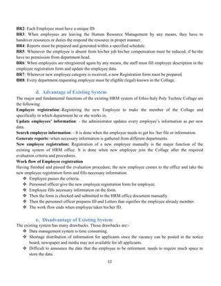
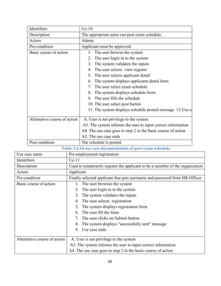
REFERENCES
[1] www.eipc.com)“ history of the Collage”
[2] J.Jones. (2001,May 15).difference between constraint and limitation(3rd
ed.)[online].online.Available:https://www.Quara.com
[3] Dianll Arthur. Managing human resource in small and midsized companies.1986, 2nd edition, amacom.
[4] William p.anthony, k.michelekacmarpamal. l.perrewe’tohumanResource management a strategic
Approach, 4th edition.
[5] Trevor Bolton, An introduction to human Resource Management, 2002 3rd edition.](https://image.slidesharecdn.com/project-210201113903/85/HRMS-61-320.jpg)

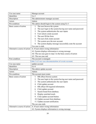
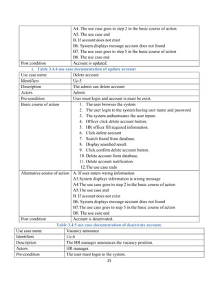
The document presents a proposal for a Human Resource Management System for Ethio-Italy Poly Technical College. The proposed system would manage all employee activities in the college more efficiently by automating the manual processes. It would reduce costs, time, and resource wastage compared to the existing system. The system would be developed using object-oriented approaches like UML modeling and iterative testing. It aims to fulfill all requirements in a well-designed, clear, and efficient manner.


![Documentation project of college management [1]](https://cdn.slidesharecdn.com/ss_thumbnails/documentationprojectofcollegemanagement1-210528071416-thumbnail.jpg?width=640&height=640&fit=bounds)


![5G Explained! A High Level Overview [Introduction]](https://cdn.slidesharecdn.com/ss_thumbnails/5gexplainedahighleveloverview-260119165306-cc137a3e-thumbnail.jpg?width=640&height=640&fit=bounds)


