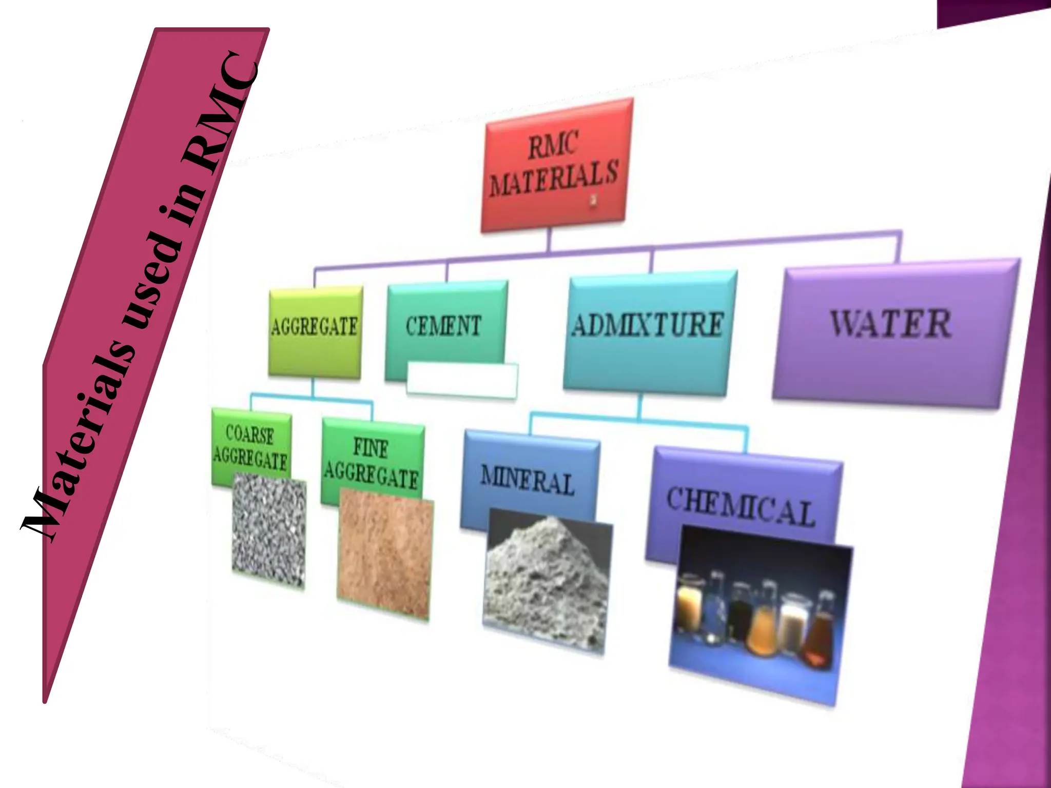
UNIT-5
 Ready-mix concrete (RMC) is a ready-to-use material, with
predetermined mixture of Cement, sand, aggregates and water.
 Ready mix concrete is a tailor made concrete which improves
durability and sustainability.
 The conventional methods of making concrete was found to be
inadequate in quality, quantity and speed to meet the need of
construction industries.
 A concrete whose constituents are weight batched at a central
batching plant, mixed either at the plant itself or in truck mixers
and then transported to the construction site and delivered in a
condition ready to use is termed as ready mix concrete.
 Ready mix concrete is produced under factory conditions and
permits a close control of all operations of manufacture and
transportation of fresh concrete.
 Quality of RMC is generally specified in terms of
performance parameters and in terms of perspective
specifications.
 RMC is ordered and supplied by volume (cubic
meter) in a freshly mixed and unhardened state.
 When ordering concrete 5 to 10% more concrete
than estimated from a volumetric calculation is
ordered.
4
 Uniform and assured quality of concrete
 Durability of concrete
 Reduction in cement consumption by 10-12%
 Faster construction speed
 Elimination of storage needs at the construction site
 Easier admixture addition
 Documentation of mix design
 Reduction in wastage of materials
 RMC is eco-friendly
1. RMC plant with supporting equipments
2. Transit mixers
3. Site equipments for handling concrete
A. Aggregate delivery
B. Aggregate receiving hopper
C. Aggregate storage
D. Conveyor belt
E. Cementing material storage
F. Weigh hopper
G. Cement delivery
H. Mixer
I. Admixtures
I. Ready mix truck with returned concrete
J. Recycled water
K. Reclaimed aggregate
L. Pump
M. Water storage
N. Concrete loaded in ready mix truck
O. Control room
8
 Capacity of 55-60 m3/h meets the requirement of a
small town with 16-18h operation.
 The supporting equipment for the plant include:
 Arrangement for unloading the bags of cements
 Fork lift truck
 Front end loader
 Weigh bridge
 Telecommunication system
 Captive diesel set
 Cement silos for 2-3- days capacity storing
 Admixture tank
 Site laboratory
 Vicat apparatus
 Blaine’s apparatus for fineness of cement
 Mortar cube vibrator
 50 cm² cube moulds
 150mm cube mould
 100*100*400mm beam mould
 Slump test apparatus
 Needle vibrator
 Compacting factor apparatus
 A set of IS sieves
 Curing tank
 Compression testing machine
 Platform balances
11
12
14
Batching Mixing Testing Transporti
ng
Placing Compac
ting
Curing
The batching equipment falls into three general
Categories
1.Manual Batching:
 For small jobs having low batch rates
2.Semiautomatic batching:
 Aggregate bin gates for charging batches are
opened by manual operated switches
 Gates are closed automatically when the
designated weight of material has been delivered.
3.Automatic batching:
 All scales for the materials are electrically
activated by single switch.
 Complete autographic records are made of the
weight of each material in each batch.
 In addition, to accurate batching of mixing water,
the amount of moisture present in the aggregate as
it is batched should be taken into account.
A mixer is generally mounted on a self-propelled
chassis, capable of mixing the ingredients of
concrete and agitating the mixed concrete during
transportation.
Usually a 4-6m³ capacity transit mixer would meet the
requirement.
1.Transit mixed
2. Central mixed
3. Shrink- mixed
1.Transit mixed: In transit mix or truck mix the materials
are batched at central plant but are mixed in a mixer
truck either in transit to the site or immediately prior to
the concrete being discharged
2.Central mixed: Here mixing is done at the central
plant and the mixed concrete is then transported,
usually in an agitator truck which revolves slowly so
as to prevent segregation and undue stiffening of mix.
3. Shrink-mixed concrete: The concrete is partially
mixed at a central plant and then discharged in to the
drum of truck mixer for completion of mixing.
 All the raw ingredients are charged directly in the truck
mixer.
 Most of the water batched into the plant.
 The mixer drum is turned at charging speed during the
loading of the materials
Three options for truck mixed concrete.
1.Concrete mixed at the job site:
 Drum is turned at agitating speed.
 After arriving, the concrete is completely mixed
 Drum is the turned for 70 to 100 revelolutions.
2. Concrete is mixed in the yard or central batching plant:
 Drum is turned at high speed or 12-15rpm for 50
revolutions
 Concrete is agitated slowly while driving
3. Concrete is nixed in transit:
 Drum is turned in medium speed or about 8rpm for 70
revolutions while driving.
 Drum is then slowed to agitating speed.
 The concrete shall be placed as soon as possible, after
delivery, as close as is practicable to its final position to
avoid re-handling or moving the concrete horizontally
by vibration.
 Depending upon the equipment for handling and
placing, the unloading and placing time for a 6m³
capacity transit mixer would be approximately as
follows:
 Truck mounted concrete pump : 6-8min
 Trailer mounted pump : 15-20min
 Tower crane and bucket : 25-30min
 Skip and hoist : 35-45 min
 However should be discharged within 30 min of arrival
at the site.
 Storage of materials – batched – mixer drum- to
trucks
 Water ponds (1.5-2.5m) to clean the truck. –
reused .
 Compressive strength test- at batching plant and
site. (7 & 28 days)
 Mix design –
 Order and supply by three ,methods:
I. Performance batch
II. Recipe batch
III. Part performance and part recipe batch
 Centrally batched concrete is manufactured in plants and
transported to various sites.
 The cement silo feeds cement directly into the weigh
hooper.
 This in turn feeds the cement directly in to the transit
mix truck.
 The aggregates are accurately weighed by the front end
loader into the weigh hooper and then transferred
directly in to the truck by means of a conveyor system.
 Trucks are washed and cleaned prior to loading each
time.
 The transportation vehicle comprises a mixing
drum on the lorry or truck chassis.
 The 3 basic methods of production and delivery
are as follows:
 The central mixer discharges into truck mixer or
agitating vehicle.
 The central mixer discharges into a special non-
agitating vehicle as a bowl or dump truck.
 Dry materials are weigh batched into a truck
mixer drum and mixing is completed at the
factory or finished on site.
 With proper access the modern truck mixer can
position itself and discharge its full load in only
10-15 min.
 Contractor handles concrete using a crane and a
bucket or with manual labour only.
 Some of the continuous handling methods are
small-diameter mobile pump and the conveyor
system.
 IS- 4926-2003 and ASTM C94.
 By ASTM C94. Time : 90 min from water added.
or before 300 revolutions of drum.
 By IS- 4926-2003 , time 2hrs from time of loading
 Transit mixer – 8-10rpm usually
 Mixed with 1000 revolutions (6m³ of concrete)
 Addition of water is allowed if concrete stiffens.
But additional 30 revolutions is given.
32
MERITS OF R.M.C.
1. Better quality concrete is produced.
2. Elimination of storage space for basic materials at site.
3. Elimination of Hiring plant and machinery
4. Wastage of basic materials is avoided.
5. Labour associated with production of concrete is
eliminated.
6. Time required is greatly reduced
7. Noise and dust pollution at site is reduced.
8 .No wastage at site
9. Environment friendly
33
DEMERITS OF R.M.C.
1. Need huge initial investment.
2. Not affordable for small projects (small quantity
of concrete)
3. Needs effective transportation system from R.M.C
to site.
4. Traffic jam or failure of vehicle creates problem if
proper dose of admixture is not given.
5. Labours should be ready on site to cast the
concrete in position to vibrate it and compact it.
6. Concrete's limited time span between mixing and
going-off means that ready-mix should be placed
within 90 minutes of batching at the plant.
45
SCOPE OF READY MIX
CONCRETE
1. Major concerting projects like dams, roads,
bridges, tunnels, canals etc.
2. For concreting in congested areas where storage of
materials is not possible.
3. Sites where intensity of traffic makes problems.
4. When supervisor and labour staff is less.
5. To reduce the time required for construction etc.
6. Huge industrial and residential projects.
46
No
Ready Mix Concrete Site Mix Concrete
1 Consistent Quality- concrete is made in high tech
batching plants in a computerized environment.
Quality is inconsistent–because concrete is hand
mixed.
2 Construction in double quick time. Manual mixing is time consuming. Projects take
longer time to finish.
3 Raw materials are chosen after strict quality checks Quality of raw materials is manually checked. Or
not checked at all.
4 Large quantities of concrete can be ordered. This
allows you to upgrade yourself and handle projects
of any size.
Takes more time. Repeated mixing needs to be done
for large quantities as the mixer will be too small to
handle the requirement.
5 No wastage of raw materials at your site.
Everything is pre-mixed at our plants, based on
your needs.
High wastage of raw materials due to manual
mixing.
6 No hassle of managing labour on site. We supply
ready-to-use concrete. Our well-equipped technical
crew will handle the pouring and patching of
concrete at the site.
Involves the use of labourers for mixing the
concrete on site. Management of labour means more
time, efforts and money.
7 Safe work practices – no disruption in your
schedule.
Highly unsafe. Unskilled and untrained labourers
may work carelessly resulting in dangerous working
conditions.
8 You don’t have to stock materials and watch over
them. There’s no worry about pilferage.
Risk of pilferage of raw materials is high.
36
No Year Cement
demand in
Million
Tons
Total
concrete
requirement
in million m3
Concrete
requirement
for Major
projects in
million m3
Concrete
requirement
in rural
areas in
million m3
Concrete
requirement
within domain
of RMC in
million m3
1 2006-07 145 282 55 96 131
2 2007-08 158 308 60 104 144
3 2008-09 172 335 66 113 156
4 2009-10 187 364 72 123 169
5 2010-11 204 397 78 134 185
6 2011-12 223 435 85 146 204
7 2012-13 243 474 93 159 222
8 2013-14 262 511 100 171 240
9 2014-15 283 522 108 184 260
 Ready Mix Concrete is a modern technique of production of concrete
in massive quantities away from the actual site of placing.
 It is very useful where demand of concrete is very high and
construction sites are in congested areas, where mixing on site is not
possible due to lake of storage place.
 RMC is ready to use material. It is widely adopted throughout the
world.
 It gives higher strength to the structure and it also provides higher
Durability to the structure.
 It reduces noise pollution as well as air pollution.
 The Supervisory and labour costs associated with the production of
RMC is less, and the quality of concrete is high.
 It is suitable for huge industrial and residential projects where time
plays a vital role.
 So ultimately it provides economy in the construction and better finish
to the structure.
 Hence now a days the advantages of RMC are realized by engineers
and contractors in the construction industry.
 Concrete is often required to be placed under water
or in a trench filled with the bentonite slurry.
 The satisfactory method of placing concrete under
water is by the use of tremie pipe.
 The word tremie is derived from the french word
hooper.
 A tremie pipe is a pipe having a diameter of about
20cm capable of easy coupling for increase or
decrease of length.
 A funnel is fitted to the top end to facilitate pouring
of concrete.
 When the pipe is raised and given a jerk, due to
the weight of concrete, the bottom plug falls and
the concrete gets discharged.
 Particular care must be taken at this stage to see
that the end of the tremie pipe remains inside the
concrete so that no water enters in to the pipe
from the bottom.
 Again concrete is poured over the funnel and
when the whole length of the tremie pipe is filled
with concrete, the pipe is again slightly lifted and
given slight jerk.
 The bottom end is closed with a plug or thick
polyethylene sheet or such other material and taken
below the water and made to rest at the point where
concrete is to be placed.
 Since the end is blocked no water will enter the pipe.
 The concrete having very high slump of 15-20cm is
poured in to the funnel.
 When the whole length of pipe is filled with concrete,
the tremie pipe is lifted up and a slight jerk is given
by a winch and pully arrangement.
 Care is taken all the time to keep the lower end
of the tremie pipe well embaded in the wet
concrete.
 The concrete in the tremie pipe gets discharged.
 In this way concrete work is progressed without
stopping till the concrete level comes above the
water level.
 The advantage of this method is that the concrete
doesnot get affected by water except the top
layer.
 The top layer is scrubbed or cut off to remove the
affected concrete at the end of the whole operation.
 During the course of concreting, no pumping of water
should be permitted.
 Under water concreting need not be compacted as
concrete gets automatically compacted by the
hydrostatic pressure of water.
 Shotcrete is mortar or very fine concrete deposited by
jetting it with high velocity on to a prepared surface.
 Shotcrete offers advantages over conventional
concrete in a variety of new construction and repair
works.
 It is capable of excellent bonding with a number of
materials and this may be an important consideration.
 Thin overhead vertical or horizontal surfaces
 Particularly the curved or folded sections
 Canal, reservoir and tunnel lining
 Swimming pools
 Water retaining structures
 Prestressed tanks.
 Restoration and repair of concrete structures
 Fire damaged structures
 Waterproofing of walls.
 Stabilization of rock slopes and temporary
protection of freshly excavated rock surfaces.
 In dry process the mixture of cement and damp sand
is conveyed through a delivery hose pipe to special
mechanical feeder or gun called delivery equipment.
 The mixture is metered in to the delivery hose by a
feed wheel or distributor.
 This material is carried by compressed air through
the delivery hose to a special nozzle.
 From nozzle water is introduced under pressure and
intimately mixed with other ingredients.
 This is jetted from the nozzle at high velocity on to
the surface to be shotcreted.
 The amount of water should be so adjusted that
wastage of material by rebounding is minimum.
 The water –cement ratio should be between 0.33
and 0.50
 In this process all the ingradients i,e cement,
sand , small sized coarse aggregates and water
are mixed before entering the chamber of
delivery equipment.
 The ready mixed concrete is metered in to the
feeding chamber and conveyed by compressed
air at a pressure of 5.5 – 7 atmosphere to a
nozzle.
 Additional air is injected at the nozzle to
increase the velocity and improve the gunning
pattern.
 Equipment capable of placing concrete at the
rate of 3 -9 m³/hr is available.
 The phenomenon of falling back of a part of mortar or
concrete jetted on to surface to be treated , due to high
velocity of jet is called rebound and depends upon the
water cement ratio and nature and position of the
surface treated.
 The rebound decreases with higher water cement ratio
and has higher values for vertical and overhead
surfaces.
 The rebound material falling on surface is cleaned
before being treated by shotcreating.
 The vertical distance should be treated from bottom to
top.
 The nozzle should be kept at a distance of
900mm from the surface.
 Addition of pozzolanic material to the mix
reduces the rebound by improving its plasticity.
 For the use of light weight concrete, dry mix is
preferred.
 Lower water cement ratio results in higher
strengths ,less creep and drying shrinkage and
higher durability.
 In wet process the higher durability can easily be
achieved by using air-entraining agents.
 The water cement ratio can be very accurately
controlled in wet process.
1.Preparation of surface to receive shotcrete
2. Construction of forms
3.Placement of reinforcement
4.Preparation for succeeding layers.
5.Finishing of the surface.
 Where the shotcrete is to be placed against earth
surfaces as in canal linings, the surfaces should first be
thoroughly compacted and trimmed to line and grade.
 The surface should be kept damp for several hours
before applying shotcreting.
 For repairing deteriorated concrete it is essential to
remove all unsound material.
 Chipping should be done to remove all the offsets in
the cavity which may cause abrupt change in thickness
of the repair work.
 After ensuring the shotcreting surface, it should be
sand balasted.
 The nozzleman usually scours clean the area
before applying the shotcrete with an air water
jet and then the water is shut off and all free
water is blown away by compressed air.
 The forms are usually of plywood sheeting, true to
line and dimension.
 They are adequately braced to ensure protection
against excessive vibration.
 The forms should be constructed to permit the
escape of air and rebound during the gunning
operation.
 They should also be oiled and dampened.
 Adequate and safe scaffolding is necessary so that
the nozzleman can hold the nozzle at a distance of 1
to 1.5m from the surface.
 Sufficient clearance should be provided around the
reinforcement to permit complete encasement with
the shotcrete.
 The minimum clearance between the reinforcement
and the form may vary between 12mm for the case of
a mortar mix and wire mesh reinforcement to 50mm
for the case of concrete and reinforcing bar.
 The receiving layer should be allowed to take its
initial set before applying a fresh layer of shotcrete.
 All laitance , loose material and rebound should be
removed by brooming.
 Any laitance which has been allowed to take final set
should be removed by sand blasting and the surface
is cleaned with air-water jet.
 Natural gun finish is preferred from both structural
and durability standpoints.
 There is a possibility that further finishing may
disturb the section, harming the bond between
shotcrete and underlying material and creating cracks
in the shotcrete.
 Where greater smoothness and better appearance is
required special finishes must be applied.
80
WHAT IS SCC ?
Self-compacting concrete (SCC)
describes a concrete with the ability to
compact itself only by means of its own
weight without the requirement of vibration.
Self-compacting concrete also known as
Self-consolidating concrete or self levelling
concrete.
81
HISTORY OF SCC
 FIRST DEVELOPED IN JAPAN IN LATE 1980’S where
the lack of uniform and complete compaction had been
identified as the primary factor responsible for poor
performance of concrete structures.
 This led to the development of the first practicable SCC
by researchers (Okamura, Ozawa et al.) at the University
of Tokyo and the large Japanese contractors (e.g. Kajima,
Maeda, Taisei etc.) quickly took up the idea.
 Self-compacting concrete has been successfully used in
France, Denmark, the Netherlands, UK, USA, and
Germany apart from Japan.
 Originally developed in Japan to offset a growing
shortage of skilled labour, it has proved to be
beneficial from following points:
 Faster construction
 Reduction in site manpower
 Better surface finish
 Easier placing
 Improved durability
 Thinner concrete sections
 Safe working environment
 Reduced noise level.
 Cement: Ordinary Portland cement 43 or 53 grade
can be used.
 Aggregates: Maximum size of aggregate is
generally limited to 20mm.
 Well graded cubical or rounded aggregates are
desirable.
 Aggregates should be of uniform quality with
respect to shape and grading.
 Grading of fine aggregates must be uniform
throughout the work.
 Mixing water: Water quality must be established on
the same line as that for using prestressed or
reinforced concrete.
 Chemical admixtures: Super plasticizers are essential
components of SCC to provide necessary workability.
 The new generation super plasticizers termed poly-
carboxylated ethers (PCE) is particularly useful for
SCC.
 Other types such as Viscosity Modifying Agents
(VMA) for stability , air entraining agents (AEA) to
improve freeze-thaw resistance and retarders for
control of setting.
 Fly ash: In appropriate quantity is added to improve
the quality and durability of SCC.
 GGBFS: Added to improve rheological properties.
 Silica fume: Silica fume may be added to improve
the mechanical properties of SCC.
 Stone Powder: Finely crushed limestone , granite
may be added to increase the powder content. The
fraction should be less than 125micron.
 Fibres: Fibres may be used to enhance the properties
of SCC in the same way as for normal concrete.
1.Shortening of construction period
2.It eliminates noise due to vibration: effective
especially at concrete products plants
3.Reduction in site man power
4.Better surface finishes.
5.Easier placing
6.Improved durability
7.Greater freedom in design
8.Thinner sections
9.High strength concrete
86
SL.NO METHOD PROPERTY
1 SLUMP FLOW BY ABRAMS
CONE
FILLING ABILITY
2 T50 SLUMP FLOW FILLING ABILITY
3 J – RING PASSING ABILITY
4 V- FUNNEL FILLING ABILITY
5 V- FUNNEL AT T5 MINUTES SEGREGATION RESISTANCE
6 L- BOX PASSING ABILITY
7 U-BOX PASSING ABILITY
8 FILL- BOX PASSING ABILITY
9 GTM SCREEN STABILITY
TEST
SEGREGATION RESISTANCE
10 ORIMET FILLING ABILITY
 The slump flow test is done to access the horizontal flow
of concrete in the absence of obstructions.
 Slump cone with base diameter of 200mm, top diameter
100mm and height 300mm.
Procedure:
 About 6lts of concrete is needed for this test.
 Place the base plate on level ground.
 Keep the slump cone centrally on the base plate.
 Fill the cone with scoop and do not tamp.
 Level the top surface with trowel and remove surplus
concrete lying on the base plate.
 Rise the cone vertically and allow the concrete to flow
freely.
 Measure the final diameter of the concrete in two
perpendicular directions and calculate the average of
the two diameters. This is the slump flow in mm.
 The higher the flow value the greater its ability to fill
formwork under its own weight.
 A value of at least 650mm is required for SCC.
90
FIG 2 : SLUMP FLOW APPARATUS
 Same as for Slump flow test.
 When the slump cone is lifted, start the stop watch
and find the time taken for the concrete to reach
500mm mark
 Time is called T50 time.
 Lower time indicates the greater flowability.
 T50 time may be 2 to 5 secs.
Equipment :
 J ring rectangular section of 30mm*25mm open steel
ring drilled vertically with holes to accept threaded
sections of reinforcing bars 10mm diameter 100mm in
length.
 The bars and sections can be placed at different distance
apart to simulate the congestion of reinforcement at the
site.
 The diameter of the ring formed by vertical sections is
300mm and height is 100mm.
Procedure:
 Moisten the inside of slump cone and base plate.
 Place the J-ring centrally on the base plate and slump
cone centrally inside the J-ring.
 Fill the slump cone with scoop do not tamp.
 Strike off the top surface with trowel and remove all
surplus concrete.
 Raise the cone vertically and allow concrete to flow
out through the J-ring.
 Measure final diameter in 2 perpendicular direction.
 Calculate the average diameter.
 Measure the difference in height between the
concrete just inside and outside the J-ring bars.
 Calculate the average of the difference in height at 4
locations in mm. (between 0-10mm)
95
FIG 4: J RING TEST
 V-funnel test is used to determine the filling ability
of the concrete with maximum size of aggregate
20mm size.
 The funnel is filled with about 12 liters of concrete.
 Find the time taken for it to flow down.
 After this the funnel can be filled with concrete and
left for 5 minutes to settle.
 Procedure: Set the V-funnel on firm ground.
 Moisten inside of the funnel.
 Keep the trap door open to remove any surplus
water.
 Close the trap door and place a bucket underneath.
 Fill the apparatus completely with concrete, no
compaction or tamping is done. Strike off the
concrete level.
 Open within 10 seconds the trap door and record
time taken for the concrete to flow down.
 Record the time for emptying. The whole test is
performed within 5 min.
 About 14lts of concrete is required for this test.
 Ensure that sliding gate can open freely and then
close it.
 Moisten the inside surface, remove all surplus water.
 Fill the vertical section of the apparatus with
concrete.
 Leave it standing for 1 minute.
 Lift the sliding gate and allow the concrete to flow
out in to the horizontal section.
 Simultaneously start the stop watch and record the
time taken for the concrete to reach 200 and 400mm
marks.
 When the concrete stops flowing the height H1 and
H2 are measured.
 Calculate H2/H1 the blocking ratio.
 The whole test has to be performed within 5
minutes.
 If the concrete flows freely as water, at rest it will be
horizontal.
 Therefore H2/H1 will be equal to 1.
 About 20 litre of concrete is needed for this test.
 Ensure that sliding gate can open freely and then
close it.
 Moisten the inside the surface and remove any
surplus water.
 Fill the one compartment of the apparatus with
about 20litre concrete.
 Leave it to stand for 1 minute.
 lift the sliding gate and allow the concrete to flow
to the other component.
 Once the concrete has come to rest, measure the
height of the concrete in the second compartment
in two places.
 Calculate the mean.
 Let it be H2.
 The height of concrete in the 1st compartment be
H1.
 Calculate H1- H2 the filling height.
 The whole test has to be completed within 5
minutes.
 Main characteristics of SCC are the properties in
fresh state.
 The mix design is focused on the ability to flow
under its own weight without vibration, the ability to
flow through heavily congested reinforcement under
its own weight and the ability to retain homogeneity
without segregation.
 A concrete mix can only be classified as self-
compacting if it has the flow characteristics such as
filling ability , Passing ability, Segregation
resistance.
 Initial mix composition:
 Water/powder ratio by volume is to be 0.80 to 1.00
 Total powder content to be 160 – 240 lts(400-600)/
m³.
 The sand content may be more than 38% of the
mortar volume.
 Coarse aggregate content should normally be 28 to
35% by volume of the mix.
 Water/cement ratio is selected based on strength. In
any case water content should not exceed 200lts/m³.

Ready Mix Concrete - concrete practices.pptx

  • 1.
  • 2.
     Ready-mix concrete(RMC) is a ready-to-use material, with predetermined mixture of Cement, sand, aggregates and water.  Ready mix concrete is a tailor made concrete which improves durability and sustainability.  The conventional methods of making concrete was found to be inadequate in quality, quantity and speed to meet the need of construction industries.  A concrete whose constituents are weight batched at a central batching plant, mixed either at the plant itself or in truck mixers and then transported to the construction site and delivered in a condition ready to use is termed as ready mix concrete.  Ready mix concrete is produced under factory conditions and permits a close control of all operations of manufacture and transportation of fresh concrete.
  • 3.
     Quality ofRMC is generally specified in terms of performance parameters and in terms of perspective specifications.  RMC is ordered and supplied by volume (cubic meter) in a freshly mixed and unhardened state.  When ordering concrete 5 to 10% more concrete than estimated from a volumetric calculation is ordered.
  • 4.
  • 5.
     Uniform andassured quality of concrete  Durability of concrete  Reduction in cement consumption by 10-12%  Faster construction speed  Elimination of storage needs at the construction site  Easier admixture addition  Documentation of mix design  Reduction in wastage of materials  RMC is eco-friendly
  • 6.
    1. RMC plantwith supporting equipments 2. Transit mixers 3. Site equipments for handling concrete
  • 7.
    A. Aggregate delivery B.Aggregate receiving hopper C. Aggregate storage D. Conveyor belt E. Cementing material storage F. Weigh hopper G. Cement delivery H. Mixer I. Admixtures I. Ready mix truck with returned concrete J. Recycled water K. Reclaimed aggregate L. Pump M. Water storage N. Concrete loaded in ready mix truck O. Control room
  • 8.
  • 9.
     Capacity of55-60 m3/h meets the requirement of a small town with 16-18h operation.  The supporting equipment for the plant include:  Arrangement for unloading the bags of cements  Fork lift truck  Front end loader  Weigh bridge  Telecommunication system  Captive diesel set  Cement silos for 2-3- days capacity storing  Admixture tank  Site laboratory
  • 10.
     Vicat apparatus Blaine’s apparatus for fineness of cement  Mortar cube vibrator  50 cm² cube moulds  150mm cube mould  100*100*400mm beam mould  Slump test apparatus  Needle vibrator  Compacting factor apparatus  A set of IS sieves  Curing tank  Compression testing machine  Platform balances
  • 11.
  • 12.
  • 14.
    14 Batching Mixing TestingTransporti ng Placing Compac ting Curing
  • 15.
    The batching equipmentfalls into three general Categories 1.Manual Batching:  For small jobs having low batch rates 2.Semiautomatic batching:  Aggregate bin gates for charging batches are opened by manual operated switches  Gates are closed automatically when the designated weight of material has been delivered.
  • 16.
    3.Automatic batching:  Allscales for the materials are electrically activated by single switch.  Complete autographic records are made of the weight of each material in each batch.  In addition, to accurate batching of mixing water, the amount of moisture present in the aggregate as it is batched should be taken into account.
  • 17.
    A mixer isgenerally mounted on a self-propelled chassis, capable of mixing the ingredients of concrete and agitating the mixed concrete during transportation. Usually a 4-6m³ capacity transit mixer would meet the requirement. 1.Transit mixed 2. Central mixed 3. Shrink- mixed 1.Transit mixed: In transit mix or truck mix the materials are batched at central plant but are mixed in a mixer truck either in transit to the site or immediately prior to the concrete being discharged
  • 18.
    2.Central mixed: Heremixing is done at the central plant and the mixed concrete is then transported, usually in an agitator truck which revolves slowly so as to prevent segregation and undue stiffening of mix. 3. Shrink-mixed concrete: The concrete is partially mixed at a central plant and then discharged in to the drum of truck mixer for completion of mixing.
  • 19.
     All theraw ingredients are charged directly in the truck mixer.  Most of the water batched into the plant.  The mixer drum is turned at charging speed during the loading of the materials Three options for truck mixed concrete. 1.Concrete mixed at the job site:  Drum is turned at agitating speed.  After arriving, the concrete is completely mixed  Drum is the turned for 70 to 100 revelolutions.
  • 20.
    2. Concrete ismixed in the yard or central batching plant:  Drum is turned at high speed or 12-15rpm for 50 revolutions  Concrete is agitated slowly while driving 3. Concrete is nixed in transit:  Drum is turned in medium speed or about 8rpm for 70 revolutions while driving.  Drum is then slowed to agitating speed.
  • 22.
     The concreteshall be placed as soon as possible, after delivery, as close as is practicable to its final position to avoid re-handling or moving the concrete horizontally by vibration.  Depending upon the equipment for handling and placing, the unloading and placing time for a 6m³ capacity transit mixer would be approximately as follows:  Truck mounted concrete pump : 6-8min  Trailer mounted pump : 15-20min  Tower crane and bucket : 25-30min  Skip and hoist : 35-45 min  However should be discharged within 30 min of arrival at the site.
  • 27.
     Storage ofmaterials – batched – mixer drum- to trucks  Water ponds (1.5-2.5m) to clean the truck. – reused .  Compressive strength test- at batching plant and site. (7 & 28 days)  Mix design –  Order and supply by three ,methods: I. Performance batch II. Recipe batch III. Part performance and part recipe batch
  • 28.
     Centrally batchedconcrete is manufactured in plants and transported to various sites.  The cement silo feeds cement directly into the weigh hooper.  This in turn feeds the cement directly in to the transit mix truck.  The aggregates are accurately weighed by the front end loader into the weigh hooper and then transferred directly in to the truck by means of a conveyor system.  Trucks are washed and cleaned prior to loading each time.
  • 29.
     The transportationvehicle comprises a mixing drum on the lorry or truck chassis.  The 3 basic methods of production and delivery are as follows:  The central mixer discharges into truck mixer or agitating vehicle.  The central mixer discharges into a special non- agitating vehicle as a bowl or dump truck.  Dry materials are weigh batched into a truck mixer drum and mixing is completed at the factory or finished on site.
  • 30.
     With properaccess the modern truck mixer can position itself and discharge its full load in only 10-15 min.  Contractor handles concrete using a crane and a bucket or with manual labour only.  Some of the continuous handling methods are small-diameter mobile pump and the conveyor system.
  • 31.
     IS- 4926-2003and ASTM C94.  By ASTM C94. Time : 90 min from water added. or before 300 revolutions of drum.  By IS- 4926-2003 , time 2hrs from time of loading  Transit mixer – 8-10rpm usually  Mixed with 1000 revolutions (6m³ of concrete)  Addition of water is allowed if concrete stiffens. But additional 30 revolutions is given.
  • 32.
  • 33.
    MERITS OF R.M.C. 1.Better quality concrete is produced. 2. Elimination of storage space for basic materials at site. 3. Elimination of Hiring plant and machinery 4. Wastage of basic materials is avoided. 5. Labour associated with production of concrete is eliminated. 6. Time required is greatly reduced 7. Noise and dust pollution at site is reduced. 8 .No wastage at site 9. Environment friendly 33
  • 34.
    DEMERITS OF R.M.C. 1.Need huge initial investment. 2. Not affordable for small projects (small quantity of concrete) 3. Needs effective transportation system from R.M.C to site. 4. Traffic jam or failure of vehicle creates problem if proper dose of admixture is not given. 5. Labours should be ready on site to cast the concrete in position to vibrate it and compact it. 6. Concrete's limited time span between mixing and going-off means that ready-mix should be placed within 90 minutes of batching at the plant. 45
  • 35.
    SCOPE OF READYMIX CONCRETE 1. Major concerting projects like dams, roads, bridges, tunnels, canals etc. 2. For concreting in congested areas where storage of materials is not possible. 3. Sites where intensity of traffic makes problems. 4. When supervisor and labour staff is less. 5. To reduce the time required for construction etc. 6. Huge industrial and residential projects. 46
  • 36.
    No Ready Mix ConcreteSite Mix Concrete 1 Consistent Quality- concrete is made in high tech batching plants in a computerized environment. Quality is inconsistent–because concrete is hand mixed. 2 Construction in double quick time. Manual mixing is time consuming. Projects take longer time to finish. 3 Raw materials are chosen after strict quality checks Quality of raw materials is manually checked. Or not checked at all. 4 Large quantities of concrete can be ordered. This allows you to upgrade yourself and handle projects of any size. Takes more time. Repeated mixing needs to be done for large quantities as the mixer will be too small to handle the requirement. 5 No wastage of raw materials at your site. Everything is pre-mixed at our plants, based on your needs. High wastage of raw materials due to manual mixing. 6 No hassle of managing labour on site. We supply ready-to-use concrete. Our well-equipped technical crew will handle the pouring and patching of concrete at the site. Involves the use of labourers for mixing the concrete on site. Management of labour means more time, efforts and money. 7 Safe work practices – no disruption in your schedule. Highly unsafe. Unskilled and untrained labourers may work carelessly resulting in dangerous working conditions. 8 You don’t have to stock materials and watch over them. There’s no worry about pilferage. Risk of pilferage of raw materials is high. 36
  • 37.
    No Year Cement demandin Million Tons Total concrete requirement in million m3 Concrete requirement for Major projects in million m3 Concrete requirement in rural areas in million m3 Concrete requirement within domain of RMC in million m3 1 2006-07 145 282 55 96 131 2 2007-08 158 308 60 104 144 3 2008-09 172 335 66 113 156 4 2009-10 187 364 72 123 169 5 2010-11 204 397 78 134 185 6 2011-12 223 435 85 146 204 7 2012-13 243 474 93 159 222 8 2013-14 262 511 100 171 240 9 2014-15 283 522 108 184 260
  • 38.
     Ready MixConcrete is a modern technique of production of concrete in massive quantities away from the actual site of placing.  It is very useful where demand of concrete is very high and construction sites are in congested areas, where mixing on site is not possible due to lake of storage place.  RMC is ready to use material. It is widely adopted throughout the world.  It gives higher strength to the structure and it also provides higher Durability to the structure.  It reduces noise pollution as well as air pollution.  The Supervisory and labour costs associated with the production of RMC is less, and the quality of concrete is high.  It is suitable for huge industrial and residential projects where time plays a vital role.  So ultimately it provides economy in the construction and better finish to the structure.  Hence now a days the advantages of RMC are realized by engineers and contractors in the construction industry.
  • 39.
     Concrete isoften required to be placed under water or in a trench filled with the bentonite slurry.  The satisfactory method of placing concrete under water is by the use of tremie pipe.  The word tremie is derived from the french word hooper.  A tremie pipe is a pipe having a diameter of about 20cm capable of easy coupling for increase or decrease of length.  A funnel is fitted to the top end to facilitate pouring of concrete.
  • 44.
     When thepipe is raised and given a jerk, due to the weight of concrete, the bottom plug falls and the concrete gets discharged.  Particular care must be taken at this stage to see that the end of the tremie pipe remains inside the concrete so that no water enters in to the pipe from the bottom.  Again concrete is poured over the funnel and when the whole length of the tremie pipe is filled with concrete, the pipe is again slightly lifted and given slight jerk.
  • 45.
     The bottomend is closed with a plug or thick polyethylene sheet or such other material and taken below the water and made to rest at the point where concrete is to be placed.  Since the end is blocked no water will enter the pipe.  The concrete having very high slump of 15-20cm is poured in to the funnel.  When the whole length of pipe is filled with concrete, the tremie pipe is lifted up and a slight jerk is given by a winch and pully arrangement.
  • 46.
     Care istaken all the time to keep the lower end of the tremie pipe well embaded in the wet concrete.  The concrete in the tremie pipe gets discharged.  In this way concrete work is progressed without stopping till the concrete level comes above the water level.  The advantage of this method is that the concrete doesnot get affected by water except the top layer.
  • 47.
     The toplayer is scrubbed or cut off to remove the affected concrete at the end of the whole operation.  During the course of concreting, no pumping of water should be permitted.  Under water concreting need not be compacted as concrete gets automatically compacted by the hydrostatic pressure of water.
  • 63.
     Shotcrete ismortar or very fine concrete deposited by jetting it with high velocity on to a prepared surface.  Shotcrete offers advantages over conventional concrete in a variety of new construction and repair works.  It is capable of excellent bonding with a number of materials and this may be an important consideration.
  • 65.
     Thin overheadvertical or horizontal surfaces  Particularly the curved or folded sections  Canal, reservoir and tunnel lining  Swimming pools  Water retaining structures  Prestressed tanks.  Restoration and repair of concrete structures  Fire damaged structures  Waterproofing of walls.  Stabilization of rock slopes and temporary protection of freshly excavated rock surfaces.
  • 66.
     In dryprocess the mixture of cement and damp sand is conveyed through a delivery hose pipe to special mechanical feeder or gun called delivery equipment.  The mixture is metered in to the delivery hose by a feed wheel or distributor.  This material is carried by compressed air through the delivery hose to a special nozzle.  From nozzle water is introduced under pressure and intimately mixed with other ingredients.  This is jetted from the nozzle at high velocity on to the surface to be shotcreted.
  • 67.
     The amountof water should be so adjusted that wastage of material by rebounding is minimum.  The water –cement ratio should be between 0.33 and 0.50
  • 68.
     In thisprocess all the ingradients i,e cement, sand , small sized coarse aggregates and water are mixed before entering the chamber of delivery equipment.  The ready mixed concrete is metered in to the feeding chamber and conveyed by compressed air at a pressure of 5.5 – 7 atmosphere to a nozzle.  Additional air is injected at the nozzle to increase the velocity and improve the gunning pattern.  Equipment capable of placing concrete at the rate of 3 -9 m³/hr is available.
  • 69.
     The phenomenonof falling back of a part of mortar or concrete jetted on to surface to be treated , due to high velocity of jet is called rebound and depends upon the water cement ratio and nature and position of the surface treated.  The rebound decreases with higher water cement ratio and has higher values for vertical and overhead surfaces.  The rebound material falling on surface is cleaned before being treated by shotcreating.  The vertical distance should be treated from bottom to top.
  • 70.
     The nozzleshould be kept at a distance of 900mm from the surface.  Addition of pozzolanic material to the mix reduces the rebound by improving its plasticity.
  • 71.
     For theuse of light weight concrete, dry mix is preferred.  Lower water cement ratio results in higher strengths ,less creep and drying shrinkage and higher durability.  In wet process the higher durability can easily be achieved by using air-entraining agents.  The water cement ratio can be very accurately controlled in wet process.
  • 72.
    1.Preparation of surfaceto receive shotcrete 2. Construction of forms 3.Placement of reinforcement 4.Preparation for succeeding layers. 5.Finishing of the surface.
  • 73.
     Where theshotcrete is to be placed against earth surfaces as in canal linings, the surfaces should first be thoroughly compacted and trimmed to line and grade.  The surface should be kept damp for several hours before applying shotcreting.  For repairing deteriorated concrete it is essential to remove all unsound material.  Chipping should be done to remove all the offsets in the cavity which may cause abrupt change in thickness of the repair work.  After ensuring the shotcreting surface, it should be sand balasted.
  • 74.
     The nozzlemanusually scours clean the area before applying the shotcrete with an air water jet and then the water is shut off and all free water is blown away by compressed air.
  • 75.
     The formsare usually of plywood sheeting, true to line and dimension.  They are adequately braced to ensure protection against excessive vibration.  The forms should be constructed to permit the escape of air and rebound during the gunning operation.  They should also be oiled and dampened.  Adequate and safe scaffolding is necessary so that the nozzleman can hold the nozzle at a distance of 1 to 1.5m from the surface.
  • 77.
     Sufficient clearanceshould be provided around the reinforcement to permit complete encasement with the shotcrete.  The minimum clearance between the reinforcement and the form may vary between 12mm for the case of a mortar mix and wire mesh reinforcement to 50mm for the case of concrete and reinforcing bar.
  • 78.
     The receivinglayer should be allowed to take its initial set before applying a fresh layer of shotcrete.  All laitance , loose material and rebound should be removed by brooming.  Any laitance which has been allowed to take final set should be removed by sand blasting and the surface is cleaned with air-water jet.
  • 79.
     Natural gunfinish is preferred from both structural and durability standpoints.  There is a possibility that further finishing may disturb the section, harming the bond between shotcrete and underlying material and creating cracks in the shotcrete.  Where greater smoothness and better appearance is required special finishes must be applied.
  • 80.
    80 WHAT IS SCC? Self-compacting concrete (SCC) describes a concrete with the ability to compact itself only by means of its own weight without the requirement of vibration. Self-compacting concrete also known as Self-consolidating concrete or self levelling concrete.
  • 81.
    81 HISTORY OF SCC FIRST DEVELOPED IN JAPAN IN LATE 1980’S where the lack of uniform and complete compaction had been identified as the primary factor responsible for poor performance of concrete structures.  This led to the development of the first practicable SCC by researchers (Okamura, Ozawa et al.) at the University of Tokyo and the large Japanese contractors (e.g. Kajima, Maeda, Taisei etc.) quickly took up the idea.  Self-compacting concrete has been successfully used in France, Denmark, the Netherlands, UK, USA, and Germany apart from Japan.
  • 82.
     Originally developedin Japan to offset a growing shortage of skilled labour, it has proved to be beneficial from following points:  Faster construction  Reduction in site manpower  Better surface finish  Easier placing  Improved durability  Thinner concrete sections  Safe working environment  Reduced noise level.
  • 83.
     Cement: OrdinaryPortland cement 43 or 53 grade can be used.  Aggregates: Maximum size of aggregate is generally limited to 20mm.  Well graded cubical or rounded aggregates are desirable.  Aggregates should be of uniform quality with respect to shape and grading.  Grading of fine aggregates must be uniform throughout the work.  Mixing water: Water quality must be established on the same line as that for using prestressed or reinforced concrete.
  • 84.
     Chemical admixtures:Super plasticizers are essential components of SCC to provide necessary workability.  The new generation super plasticizers termed poly- carboxylated ethers (PCE) is particularly useful for SCC.  Other types such as Viscosity Modifying Agents (VMA) for stability , air entraining agents (AEA) to improve freeze-thaw resistance and retarders for control of setting.
  • 85.
     Fly ash:In appropriate quantity is added to improve the quality and durability of SCC.  GGBFS: Added to improve rheological properties.  Silica fume: Silica fume may be added to improve the mechanical properties of SCC.  Stone Powder: Finely crushed limestone , granite may be added to increase the powder content. The fraction should be less than 125micron.  Fibres: Fibres may be used to enhance the properties of SCC in the same way as for normal concrete.
  • 86.
    1.Shortening of constructionperiod 2.It eliminates noise due to vibration: effective especially at concrete products plants 3.Reduction in site man power 4.Better surface finishes. 5.Easier placing 6.Improved durability 7.Greater freedom in design 8.Thinner sections 9.High strength concrete 86
  • 87.
    SL.NO METHOD PROPERTY 1SLUMP FLOW BY ABRAMS CONE FILLING ABILITY 2 T50 SLUMP FLOW FILLING ABILITY 3 J – RING PASSING ABILITY 4 V- FUNNEL FILLING ABILITY 5 V- FUNNEL AT T5 MINUTES SEGREGATION RESISTANCE 6 L- BOX PASSING ABILITY 7 U-BOX PASSING ABILITY 8 FILL- BOX PASSING ABILITY 9 GTM SCREEN STABILITY TEST SEGREGATION RESISTANCE 10 ORIMET FILLING ABILITY
  • 88.
     The slumpflow test is done to access the horizontal flow of concrete in the absence of obstructions.  Slump cone with base diameter of 200mm, top diameter 100mm and height 300mm. Procedure:  About 6lts of concrete is needed for this test.  Place the base plate on level ground.  Keep the slump cone centrally on the base plate.  Fill the cone with scoop and do not tamp.  Level the top surface with trowel and remove surplus concrete lying on the base plate.  Rise the cone vertically and allow the concrete to flow freely.
  • 89.
     Measure thefinal diameter of the concrete in two perpendicular directions and calculate the average of the two diameters. This is the slump flow in mm.  The higher the flow value the greater its ability to fill formwork under its own weight.  A value of at least 650mm is required for SCC.
  • 90.
    90 FIG 2 :SLUMP FLOW APPARATUS
  • 91.
     Same asfor Slump flow test.  When the slump cone is lifted, start the stop watch and find the time taken for the concrete to reach 500mm mark  Time is called T50 time.  Lower time indicates the greater flowability.  T50 time may be 2 to 5 secs.
  • 92.
    Equipment :  Jring rectangular section of 30mm*25mm open steel ring drilled vertically with holes to accept threaded sections of reinforcing bars 10mm diameter 100mm in length.  The bars and sections can be placed at different distance apart to simulate the congestion of reinforcement at the site.  The diameter of the ring formed by vertical sections is 300mm and height is 100mm. Procedure:  Moisten the inside of slump cone and base plate.  Place the J-ring centrally on the base plate and slump cone centrally inside the J-ring.
  • 94.
     Fill theslump cone with scoop do not tamp.  Strike off the top surface with trowel and remove all surplus concrete.  Raise the cone vertically and allow concrete to flow out through the J-ring.  Measure final diameter in 2 perpendicular direction.  Calculate the average diameter.  Measure the difference in height between the concrete just inside and outside the J-ring bars.  Calculate the average of the difference in height at 4 locations in mm. (between 0-10mm)
  • 95.
    95 FIG 4: JRING TEST
  • 96.
     V-funnel testis used to determine the filling ability of the concrete with maximum size of aggregate 20mm size.  The funnel is filled with about 12 liters of concrete.  Find the time taken for it to flow down.  After this the funnel can be filled with concrete and left for 5 minutes to settle.  Procedure: Set the V-funnel on firm ground.  Moisten inside of the funnel.  Keep the trap door open to remove any surplus water.
  • 97.
     Close thetrap door and place a bucket underneath.  Fill the apparatus completely with concrete, no compaction or tamping is done. Strike off the concrete level.  Open within 10 seconds the trap door and record time taken for the concrete to flow down.  Record the time for emptying. The whole test is performed within 5 min.
  • 99.
     About 14ltsof concrete is required for this test.  Ensure that sliding gate can open freely and then close it.  Moisten the inside surface, remove all surplus water.  Fill the vertical section of the apparatus with concrete.  Leave it standing for 1 minute.  Lift the sliding gate and allow the concrete to flow out in to the horizontal section.  Simultaneously start the stop watch and record the time taken for the concrete to reach 200 and 400mm marks.
  • 101.
     When theconcrete stops flowing the height H1 and H2 are measured.  Calculate H2/H1 the blocking ratio.  The whole test has to be performed within 5 minutes.  If the concrete flows freely as water, at rest it will be horizontal.  Therefore H2/H1 will be equal to 1.
  • 102.
     About 20litre of concrete is needed for this test.  Ensure that sliding gate can open freely and then close it.  Moisten the inside the surface and remove any surplus water.  Fill the one compartment of the apparatus with about 20litre concrete.  Leave it to stand for 1 minute.  lift the sliding gate and allow the concrete to flow to the other component.
  • 104.
     Once theconcrete has come to rest, measure the height of the concrete in the second compartment in two places.  Calculate the mean.  Let it be H2.  The height of concrete in the 1st compartment be H1.  Calculate H1- H2 the filling height.  The whole test has to be completed within 5 minutes.
  • 105.
     Main characteristicsof SCC are the properties in fresh state.  The mix design is focused on the ability to flow under its own weight without vibration, the ability to flow through heavily congested reinforcement under its own weight and the ability to retain homogeneity without segregation.  A concrete mix can only be classified as self- compacting if it has the flow characteristics such as filling ability , Passing ability, Segregation resistance.
  • 106.
     Initial mixcomposition:  Water/powder ratio by volume is to be 0.80 to 1.00  Total powder content to be 160 – 240 lts(400-600)/ m³.  The sand content may be more than 38% of the mortar volume.  Coarse aggregate content should normally be 28 to 35% by volume of the mix.  Water/cement ratio is selected based on strength. In any case water content should not exceed 200lts/m³.