The document describes a project submitted by four students - Sameer Alam, Prachi Pandey, Arvind Agrahari, and Neelam Singh - to their professor Ms. Sweta for their Bachelor of Technology degree in Computer Science and Engineering from Buddha Institute of Technology in Gorakhpur, India, in April 2017 on developing a billing software called "Quick Bill" for supermarkets.


![26
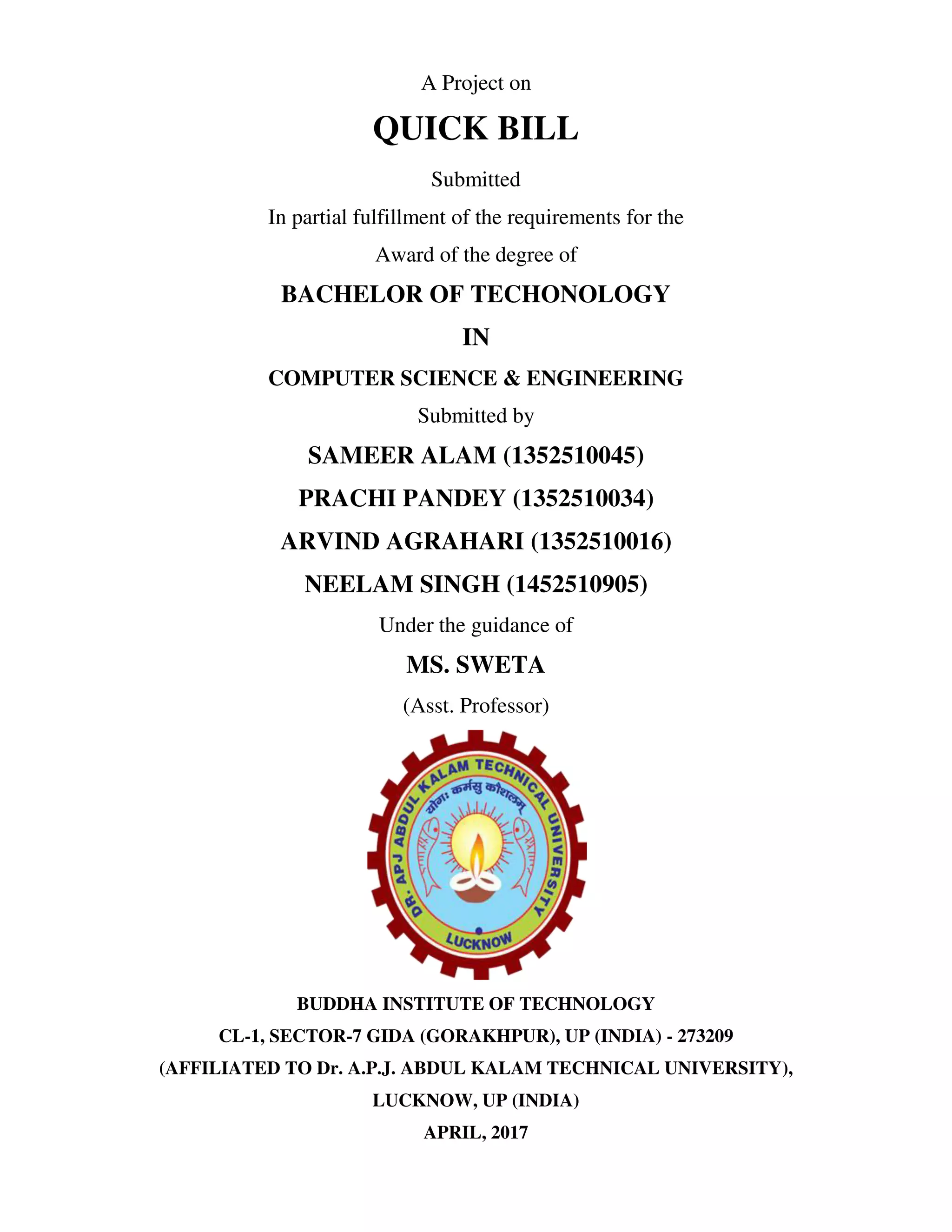
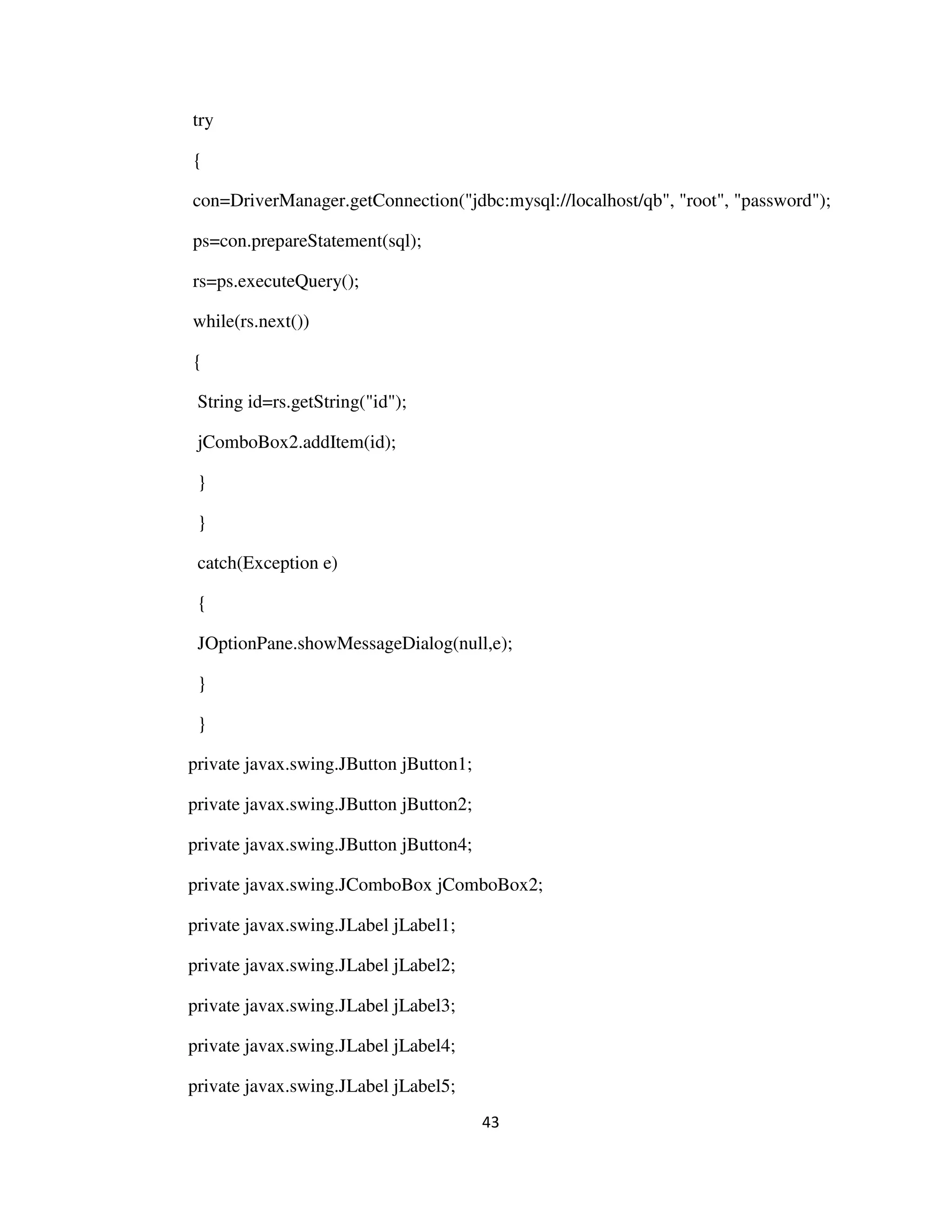
private void jButton5ActionPerformed(java.awt.event.ActionEvent evt) {
Transaction ts=new Transaction();
this.desktop.add(ts);
ts.setVisible(true);
}
private void jButton6ActionPerformed(java.awt.event.ActionEvent evt) {
Sales sa=new Sales();
this.desktop.add(sa);
sa.setVisible(true);
}
public static void main(String args[]) {
java.awt.EventQueue.invokeLater(() -> {
new MainFrame().setVisible(true)});
}
private javax.swing.JButton Cashview;
private javax.swing.JDesktopPane desktop;
private javax.swing.JButton jButton3;
private javax.swing.JButton jButton4;
private javax.swing.JButton jButton5;
private javax.swing.JButton jButton6;
private javax.swing.JLabel jLabel1;
private javax.swing.JLabel jLabel2;
private javax.swing.JMenu jMenu4;
private javax.swing.JMenu jMenu5;
private javax.swing.JMenuBar jMenuBar2;](https://image.slidesharecdn.com/quickbill-170504090415/75/Quickbill-36-2048.jpg)

![30
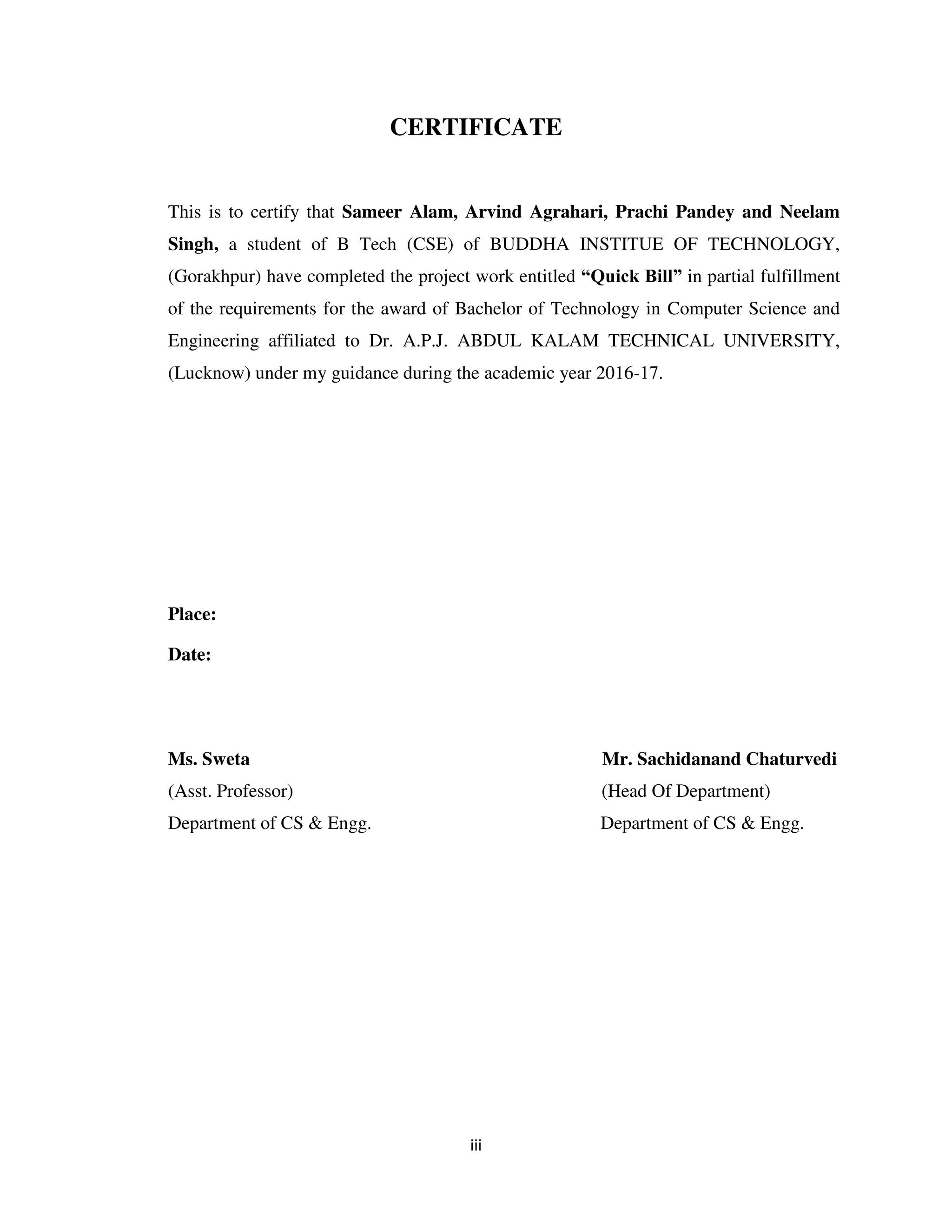
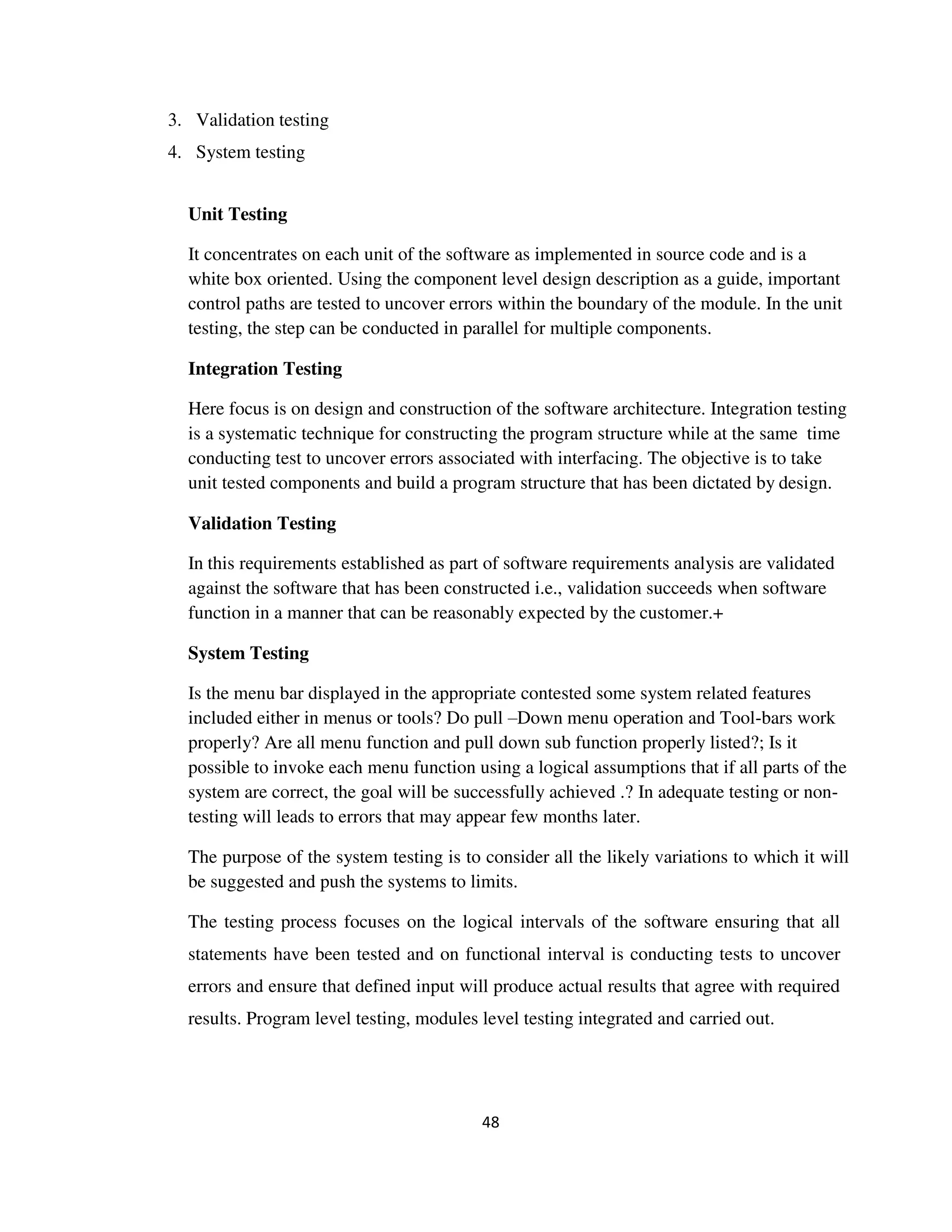
st=connection.createStatement();
rs=st.executeQuery(query);
Cash cash;
while(rs.next())
{
cash = new
Cash(rs.getInt("id"),rs.getString("name"),rs.getString("mno"),rs.getString("address"),rs.
getString("email"),rs.getString("password"));
cashList.add(cash);
}
}
catch(Exception e)
{
e.printStackTrace();
}
return cashList;
}
// Display data in JTable
public void show_cash()
{
ArrayList<Cash> list=getCashList();
DefaultTableModel model=(DefaultTableModel)jTable1.getModel();
Object[] row=new Object[6];
for(int i=0;i<list.size();i++)
{
row[0]=list.get(i).getid();](https://image.slidesharecdn.com/quickbill-170504090415/75/Quickbill-40-2048.jpg)
![31
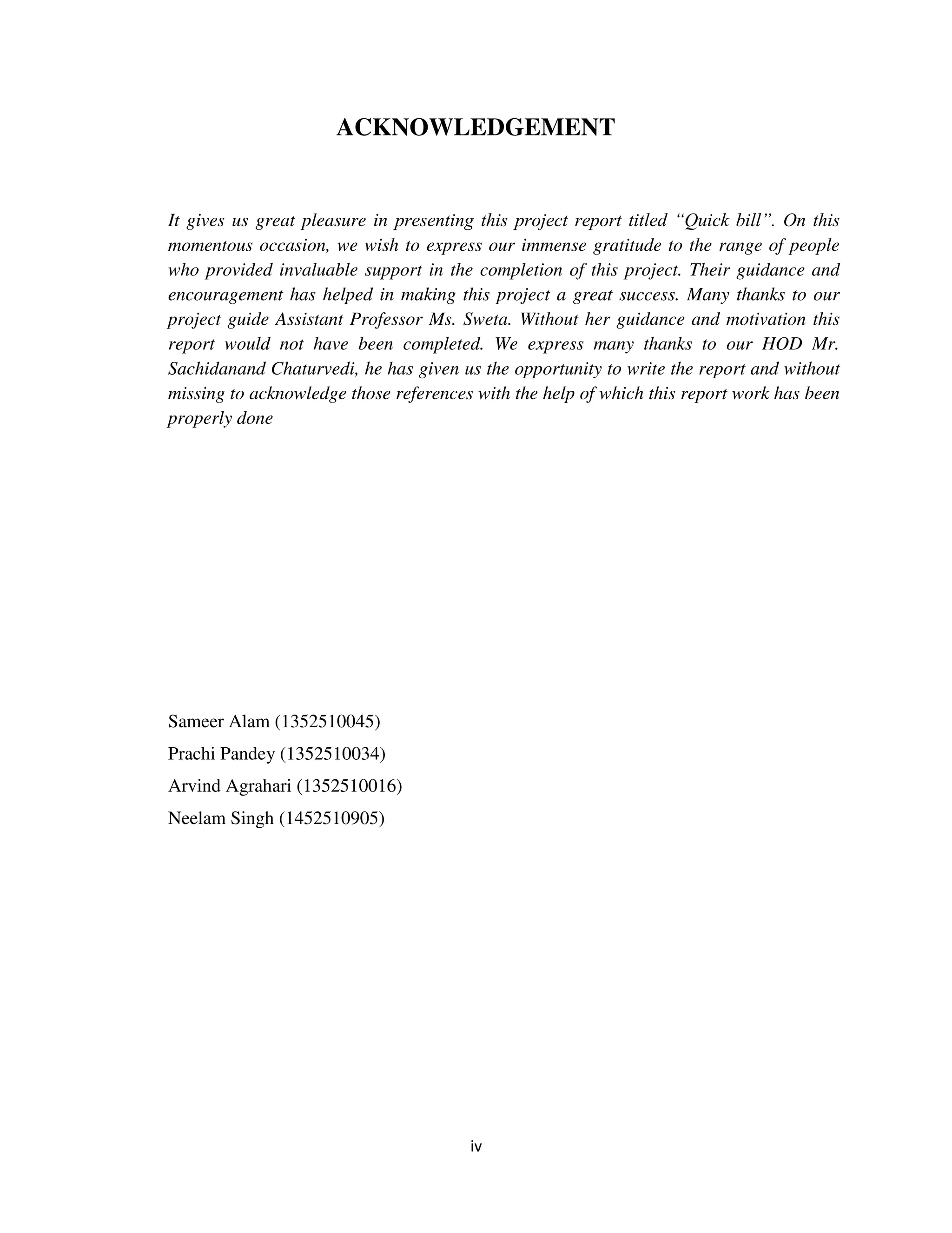
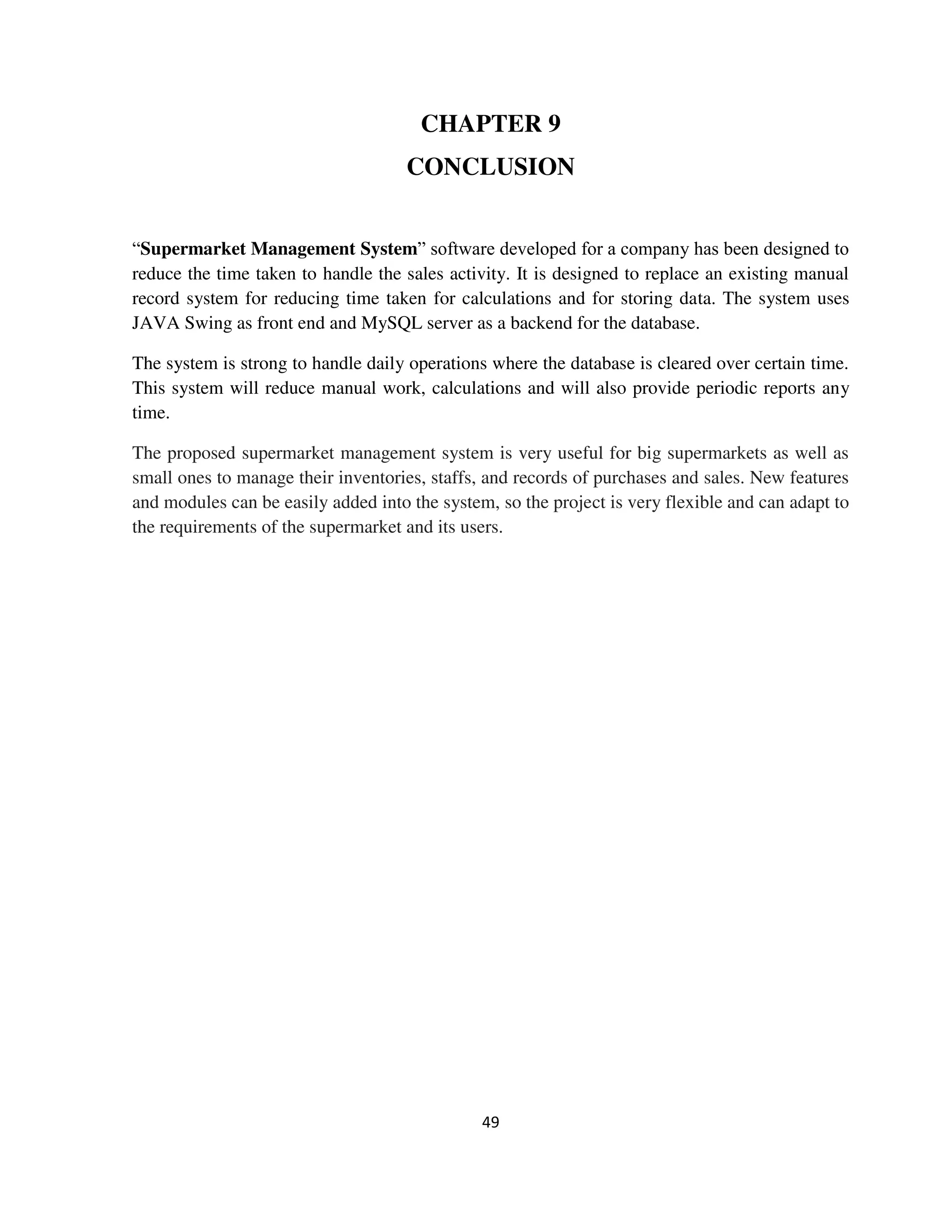
row[1]=list.get(i).getname();
row[2]=list.get(i).getmno();
row[3]=list.get(i).getaddress();
row[4]=list.get(i).getemail();
row[5]=list.get(i).getpassword();
model.addRow(row);
}
}
public void executeSQlQuery(String query, String message)
{
Connection con = getConnection();
Statement st;
try{
st = con.createStatement();
if((st.executeUpdate(query)) == 1)
{
// refresh jtable data
DefaultTableModel model = (DefaultTableModel)jTable1.getModel();
model.setRowCount(0);
show_cash();
jTextField1.setText("");
jTextField2.setText("");
jTextField3.setText("");
jTextField4.setText("");](https://image.slidesharecdn.com/quickbill-170504090415/75/Quickbill-41-2048.jpg)


![39
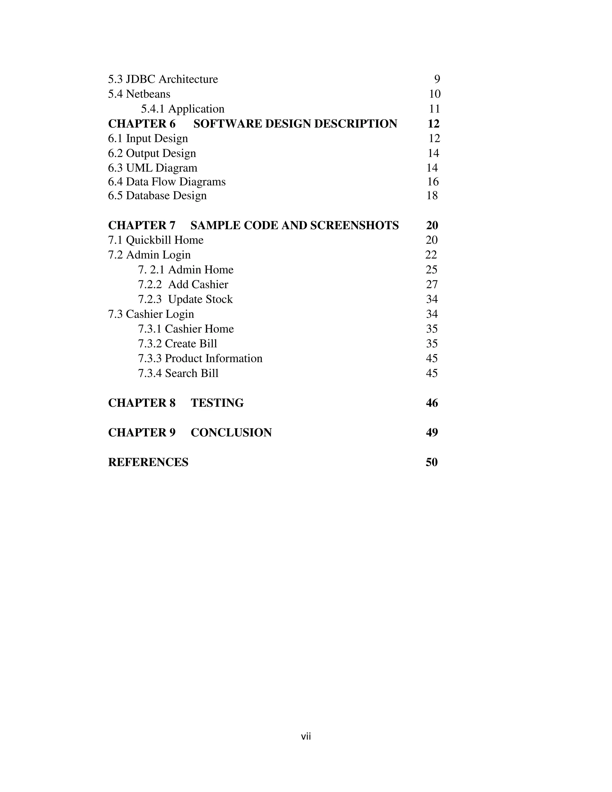
st = con.createStatement();
st.executeUpdate(query);
}
catch(Exception e)
{
JOptionPane.showMessageDialog(null ,e);
}
}
//Sum of jtable
private void jButton1ActionPerformed(java.awt.event.ActionEvent evt) {
DefaultTableModel model =(DefaultTableModel) jTable1.getModel();
String s2= jTextField5.getText();//quantity
String s1=jTextField4.getText(); //mrp
int a=Integer.parseInt(s1);
int b;
b = Integer.parseInt(s2);
int c = a * b;
String result=String.valueOf(c);
model.addRow(new
Object[]{jTextField5.getText(),jTextField3.getText(),jTextField4.getText(),result});
getsum();
// Update query;
String sql1="UPDATE `stock` SET `available`=`available` -
'"+jTextField5.getText()+"' WHERE
`id`='"+String.valueOf(jComboBox2.getSelectedItem())+"'";
Connection con;](https://image.slidesharecdn.com/quickbill-170504090415/75/Quickbill-49-2048.jpg)


![Vibe Coding vs. Spec-Driven Development [Free Meetup]](https://cdn.slidesharecdn.com/ss_thumbnails/vibecodingvsspecdrivendevelopment-251209105622-43f455e7-thumbnail.jpg?width=640&height=640&fit=bounds)


![Coded Agents – with UiPath SDK + LangGraph [Virtual Hands-on Workshop]](https://cdn.slidesharecdn.com/ss_thumbnails/codedagentsdeck-251215155422-5497c599-thumbnail.jpg?width=640&height=640&fit=bounds)


