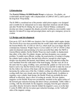
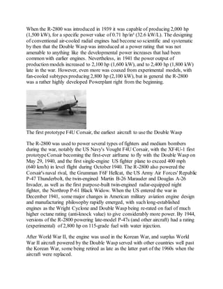
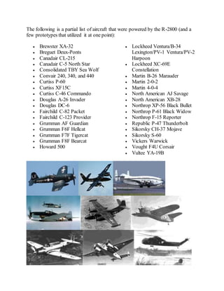
2. Preface
Throughout the semester, this course has helped me develop not only my
knowledge but has given me and idea about how an aero piston engines is
developed through the last century.
The following is specific assignment that shows my knowledge and my
progression throughout the course.
3. TABLE OF CONTENTS
SECTION TITLE
1.0 Introduction
1.1 Design and development
2.0 Peacetime
3.0 Variants
3.1 Military
4.0 Applications
5.0 Specifications (R-2800-54)
6.0 Crankshaft Development
6.1 Connecting Rod Evolution
6.2 Clamp-type Crankshaft
6.3 Face-splined Crankshaft
7.0 Conclusion
4. 1.0 Introduction
The Pratt & Whitney R-2800 Double Waspis a twin-row, 18-cylinder, air-
cooled radial aircraft engine with a displacement of 2,800 in³ (46 L), and is part of
the long-lived Wasp family.
The R-2800 is considered one of the premier radial piston engines ever designed
and is notable for its widespread use in many important American aircraft during
and after World War II. During the war years, Pratt & Whitney continued to
develop new ideas to upgrade this already powerful workhorse, most notably water
injection for takeoff in cargo and passenger planes and to give emergency power in
combat
1.1 Design and development
First run in 1937, the R-2800 was America's first 18-cylinder radial engine design.
The DoubleWasp was more powerful than the world's only other modern eighteen,
the Gnome-Rhône 18L of 3,442 in³ (56.4 L); which itself was even larger than the
contemporary American Wright Duplex-Cyclone radial of 3,347 in³ (54.86 L) then
under development (and promising to be more powerful than either the P&W or
Gnome-Rhone radials), but the Double Wasp was much smaller in displacement
than either of the other 18-cylinder designs, and heat dissipation was a greater
problem. To enable more efficient cooling, the usual practice of casting or forging
the cylinder head cooling fins that had been effective enough for other engine
designs was discarded, and instead, much thinner and closer-pitched cooling fins
were machined from the solid metal of the head forging. The fins were all cut at
the same time by a gang of milling saws, automatically guided as it fed across the
head in such a way that the bottom of the grooves rose and fell to make the roots of
the fins follow the contour of the head, with the elaborate process substantially
increasing the surface area of the fins. Cylinder cooling was effected by aluminum
cooling muffs that were shrunk onto the steel alloy forged barrels. In addition to
requiring a new cylinder head design, the Double Wasp was probably the most
difficult to effectively direct a flow of cooling air around. The twin ignition
magnetos on the Double Wasp were prominently mounted on the upper surface of
the forward gear reduction housing and almost always prominently visible within a
cowling, with the driveshafts for the magnetos emerging from the gear reduction
case either directly forward or directly behind the magneto's cases, or on the later
C-series R-2800s with the two-piece gear reduction housings, on the "outboard"
sides of the magneto casings.
5. When the R-2800 was introduced in 1939 it was capable of producing 2,000 hp
(1,500 kW), for a specific power value of 0.71 hp/in³ (32.6 kW/L). The designing
of conventional air-cooled radial engines had become so scientific and systematic
by then that the Double Wasp was introduced at a power rating that was not
amenable to anything like the developmental power increases that had been
common with earlier engines. Nevertheless, in 1941 the power output of
production models increased to 2,100 hp (1,600 kW), and to 2,400 hp (1,800 kW)
late in the war. However, even more was coaxed from experimental models, with
fan-cooled subtypes producing 2,800 hp (2,100 kW), but in general the R-2800
was a rather highly developed Powerplant right from the beginning.
The first prototype F4U Corsair, the earliest aircraft to use the Double Wasp
The R-2800 was used to power several types of fighters and medium bombers
during the war, notably the US Navy's Vought F4U Corsair, with the XF4U-1 first
prototypeCorsair becoming the first-ever airframe to fly with the Double Wasp on
May 29, 1940, and the first single-engine US fighter plane to exceed 400 mph
(640 km/h) in level flight during October1940. The R-2800 also powered the
Corsair's naval rival, the Grumman F6F Hellcat, the US Army Air Forces' Republic
P-47 Thunderbolt, the twin-engined Martin B-26 Marauder and Douglas A-26
Invader, as well as the first purpose-built twin-engined radar-equipped night
fighter, the Northrop P-61 Black Widow. When the US entered the war in
December 1941, some major changes in American military aviation engine design
and manufacturing philosophy rapidly emerged, with such long-established
engines as the Wright Cyclone and Double Wasp being re-rated on fuel of much
higher octane rating (anti-knock value) to give considerably more power. By 1944,
versions of the R-2800 powering late-model P-47s (and other aircraft) had a rating
(experimental) of 2,800 hp on 115-grade fuel with water injection.
After World War II, the engine was used in the Korean War, and surplus World
War II aircraft powered by the Double Wasp served with other countries well past
the Korean War, some being retired as late as the latter part of the 1960s when the
aircraft were replaced.
6.
7.
8.
9. 2.0 Peacetime
Engines naturally grow in power with development, but a major war demands the
utmost performance from engines fitted to aircraft whose life in front-line service
was unlikely to exceed 50 hours' flying, over a period of only a month or two. In
peacetime however, the call was for reliability over a period of perhaps a dozen
years, and the R-2800's reliability commended its use for long-range patrol aircraft
and for the Douglas DC-6, Martin 4-0-4, and Convair 240 transports. This last
application is noteworthy, since these were twin-engined aircraft of size, passenger
capacity, and high wing loading comparable with the DC-4 and the first
Constellations.
Today, three-quarters of a century after the first prototype Double Wasp was built
and run, it is still used in many restored vintage warbird aircraft displayed at air
shows — such as the over two dozen airworthy examples of the first airframe
design it powered, and sees frequent service worldwide on aircraft such as the
Canadair CL-215 water-bomber. In addition, many R-2800s continue to power
DC-6 cargo and fuel-carrying aircraft in locations such as Alaska. A total of
125,334 R-2800 engines were produced between 1939 and 1960.
3.0 Variants
This is a list of representative R-2800 variants, describing some of the mechanical
changes made during development of the Double-Wasp. Power ratings quoted are
usually maximum "military" power that the engine could generate on takeoff and at
altitude: 100 Octane fuel was used, unless otherwise noted.
The R-2800 was developed and modified into a basic sequence of subtypes, "A"
through "E" series, each of which indicated major internal and external
modifications and improvements, such that the "E" series engines had very few
parts in common with the "A".
3.1 Military
Notes
The dash number for each military type (e.g.: -21) was allocated to identify the
complete engine model in accordancewith the specification under which the
engine was manufactured, thus it did not necessarily indicate the sequence in
which the engines were manufactured; for example: the -18W was a "C" series
engine, built from 1945, whereas the -21 was a "B" series engine, built from 1943.
10. Until 1940 the armed forces adhered strictly to the convention that engines built for
the Army Air Forceused odd numeric suffixes (e.g.: -5), while those built for the
US Navy used even (e.g.: -8). After 1940, however, in the interests of
standardization, engines were sometimes built to a joint Army-Navy contract, in
which case the engines used a common numeric suffix (e.g.: the -10 was used by
both Army and Naval aircraft.)
The suffix W e.g.: -10W denotes a sub-series modified to use A.D.I Anti-Detonate
Injection or water injection equipment, using various mixes of water and methyl
alcohol (CH3OH) injected into the carburetor to increase power for short periods:
several models of R-2800s were fitted as standard with A.D.I and did not use the
W suffix. Few commercial aircraft used water injection.
"A" Series:
R-2800-1
1,500 hp (1,118 kW) at 2,400 rpm at 7,500 ft (2,286 m). Production
prototypeof "A" series engines with the first flight test July 29, 1939.
Single-speed two-stage supercharger. Production = 2 (P&W). Tested in
Vultee YA-19B.
R-2800-5
1,850 hp (1,379 kW) at 2,600 rpm at 2,700 ft (823 m). Main production "A"
series engine used in Martin B-26A, early B series and XB-26D and Curtiss
C-55/XC-46. Production= 1,429 (P&W 475, Ford 954.)
"B" Series:
A preserved "B Series" R-2800-21 or -59. The A and B series can be most readily
identified by their smooth, single piece nose casings. This photo shows the
simplified, tubular ignition harness fitted to some R-2800 subtypes.
11. R-2800-8
2,000 hp (1,491 kW) at 2,700 rpm at 1,000 ft (305 m); 1,800 (1,342 kW) at
2,700 rpm at 15,500 ft (4,724 m). First series production"B" Series engine
using a two-stage, two-speed supercharger and with internal engineering
changes resulting in increased power and reliability. Updraft Bendix-
Stromberg PT-13D-4 pressure carburetor. First productionengines delivered
to U.S.N November 11, 1941. Used in Brewster F3A-1, Goodyear FG-1,
Vought F4U-1 and F4U-2. Production = 3,903 (P&W 2,194; Nash 1,709.)
R-2800-8W
2,250 hp (1,677 kW) WEP with water injection. First productionengine
using ADI equipment, major production version of -8 and used in same
versions of F4U Corsair. Production = 8,668 (P&W 5,574; Nash 3,094.)
R-2800-10and R-2800-10W
2,000 hp (1,491 kW) at 2,700 rpm at 1,000 ft (305 m); 1,800 (1,342 kW) at
2,700 rpm at 15,500 ft (4,724 m); up to 2,250 hp (1,677 kW) WEP with
water injection. Similar to -8 series apart from downdraft PT-13G2-10 and
PT-13G6-10 (-10W) carburetor. Used in Curtiss XP-60E, Grumman F6F-3
(-10; late production-10W) and F6F-5 (-10W) series and Northrop XP-61,
YP-61, and P-61A-1. Production = 4,621 -10 (P&W 2,931; Nash 1,690) and
12,940 -10W (P&W 3,040; Nash 9,900); Total = 17,561.
R-2800-21
2,000 hp (1,491 kW) at 2,700 rpm at 2,500 ft (762 m); 2,000 hp (1,491 kW)
at 2,700 rpm at 25,000 ft (7,620 m). First productionvariant fed by a
General Electric C-1 turbosupercharger. Designed for use in the Republic P-
47B, C, D, G and XP-47F and K. Production = 5,720 (P&W 1,049; Ford
4,671.)
R-2800-59
2,000 hp (1,491 kW) at 2,700 rpm at 2,500 ft (762 m); 2,000 hp (1,491 kW)
at 2,500 rpm at 25,000 ft (7,620 m); 2,300 hp (1,700 kW) WEP with water
injection. Main productionvariant used in P-47 series, fed by an improved
C-23 turbosupercharger. Differed from -21 in being fitted with A.D.I and a
General Electric ignition system with a simplified, tubular ignition harness
12. developed by the Scinitilla Company in partnership with Bendix. Used in P-
47C and D, XP-47L. Production= 11,391 (P&W 592; Ford 10,799).
"C" Series
A "C Series" R-2800, with the two section nose casing incorporating torque-
monitoring equipment and a Spark Advance unit, with the "outboard" driveshaft
location for each of the twin ignition magnetos.
R-2800-18W
2,100 hp (1,566 kW) at 2,800 rpm at 1,000 ft (305 m); 1,800 hp (1,342 kW)
at 2,800 rpm at 25,500 ft (7,772 m). First series production variant of the
"C" Series, which was a complete redesign of the R-2800. Some of the main
changes were forged, rather than cast cylinders, allowing an increased
compressionratio (from 6.65:1 to 6.75:1), a redesigned crankshaft, a single
piece, rather than split crankcase center section, and a two section nose
casing, incorporating hydraulically operated torque-monitoring equipment
and an automatic, vacuum operated spark-advance unit. The supercharger
used fluid coupling for the second stage. Updraft Bendix-Stromberg PT-
13G2-10 carburetor. Used in Vought F4U-4 and -4 variants. Production=
3,257 (P&W).
4.0 Applications
Martin B-26 Marauder
13. The following is a partial list of aircraft that were powered by the R-2800 (and a
few prototypes that utilized it at one point):
Brewster XA-32
Breguet Deux-Ponts
Canadair CL-215
Canadair C-5 North Star
Consolidated TBY Sea Wolf
Convair 240, 340, and 440
Curtiss P-60
Curtiss XF15C
Curtiss C-46 Commando
Douglas A-26 Invader
Douglas DC-6
Fairchild C-82 Packet
Fairchild C-123 Provider
Grumman AF Guardian
Grumman F6F Hellcat
Grumman F7F Tigercat
Grumman F8F Bearcat
Howard 500
Lockheed Ventura/B-34
Lexington/PV-1 Ventura/PV-2
Harpoon
Lockheed XC-69E
Constellation
Martin B-26 Marauder
Martin 2-0-2
Martin 4-0-4
North American AJ Savage
North American XB-28
Northrop XP-56 Black Bullet
Northrop P-61 Black Widow
Northrop F-15 Reporter
Republic P-47 Thunderbolt
Sikorsky CH-37 Mojave
Sikorsky S-60
Vickers Warwick
Vought F4U Corsair
Vultee YA-19B
14. 5.0 Specifications (R-2800-54)
Pratt & Whitney R-2800
Data from FAA TCDS
Generalcharacteristics
Type: 18-cylinder air-cooled twin-row radial engine with water injection
Bore:5.75 in (146.05 mm)
Stroke: 6 in (152.4 mm)
Displacement: 2,804.5 in³ (45.96 L)
Diameter: 52.8 in (1,342 mm)
Dry weight: 2,360 lb (1,073 kg)
Components
Valvetrain: Poppet, two valves per cylinder
Supercharger:Variable-speed (in F8F-2, unified with throttle via AEC
automatic engine control), single-stage single-speed centrifugal type
supercharger
Fuel system: One Stromberg injection carburetor
Fuel type: 100/130 octane gasoline
Cooling system: Air-cooled
Performance
Poweroutput: 2,100 hp (1,567 kW) @ 2,700 rpm
Specific power: 0.75 hp/in³ (34.1 kW/L)
Power-to-weightratio: 0.89 hp/lb (1.46 kW/kg)
15. 6.0 Crankshaft Development
One of the things that made the original Pratt
& Whitney “Wasp”so successfulin 1926
when it first passed its type test was the
ability to make its power at a higher RPM
and a lighter weight than its competition.
Key to this accomplishment was the use of a
one-piece master rod and two-piece
crankshaft. Though twopiece crankshafts
had been built before, George Mead and
Andy Willgoos chose a new construction
consisting of a split crankpin splined to its
mating crankpin, the whole assembly being
held together with a bolt through the center
of the crankpin. "Wasp"
Crankshaft(Pratt & Whitney)
This construction was used in many, but not all, Pratt & Whitney designs
preceding the R-2800. It is therefore no surprise that the designers chosethis same
type of construction for two-throw R-2800 crankshaft. The original R-2800
crankshaft compensated for the weight of the master rod and link rods in the usual
fashion, by providing a counterweight that balanced all of the rotating mass and
one-half of the reciprocating mass. Initially, no vibration dampers of any kind were
provided. It is unclear whether this was wistful thinking on the part of the
designers, or merely acknowledgement that no one could predict the vibration
behavior anyway, so they may as well start testing to uncover the problems as early
as possible. One thing the designers did consider was placement of the master rods
as close as possible to 90 degrees to one another so that second-orderinertia
torques could cancel as nearly as possible, reducing 2X torsional excitation of the
crankshaft.
George E. Meloy was heavily involved in R-2800 crankshaft development almost
from the start. One of his first jobs at Pratt & Whitney was to write a report on the
history of R-2800 development, which included many details on the successes and
failures of the crankshaft. Meloy was later responsible for sorting out problems
with the “C” engine crankshaft and getting it into successfulproduction in the
Kansas City, Missouri plant. Some of the people who worked for Meloy remember
him for being the only personthey know who could walk into a test cell and not
get oil on his clean white shirt. Meloy was bornin Chicago in 1916, but at the age
of four moved east to New York. He eventually settled in Teaneck, New Jersey
where he graduated from Teaneck High School. Meloy received a Bachelor of
Aeronautical Engineering from New York University. Despite the scarcity of jobs
brought about by the Depression, Meloy started work at Pratt & Whitney one week
after graduation in 1938. Initially a test engineer, Meloy advanced rapidly through
project engineering and finally into management. While his real love was in
16. development, like many capable technical people, he had the management role
forced upon him. However, he did not despair. Says Meloy, “Every moment spent
at Pratt, to me, was worthwhile. I didn’t watch the clock, didn’t have to. During the
war years, we worked 54-hour weeks. There were no perks back in that time,
understandably. We were just happy to do it. It gave us a feeling we were doing
something worthwhile for the defense of the nation.”
6.1 Connecting Rod Evolution
The first one-piece master rod assembly featured a locked silver-plated bearing and
locked knuckle pins. A silver-plated flange on the forward face of the master rod
bearing carried thrust loads on the master rod. This design was discarded because
of weaknesses that became apparent during testing. By strengthening portions of
the master rod and link rods that were highly stressed, as well as increasing the
fillets and radii at stress concentration points, master and link rod structural failures
were eliminated. Aiding this process was moving knuckle pin oil delivery passages
to the knuckle pin retaining plates. Much of the master rod development was done
using brittle lacquers. These coatings were the only instrumentation available at
that time for internal engine parts. Brittle lacquers have the characteristic of
cracking when the material to which they have been applied flexes. By analyzing
the concentration and orientation of cracks in the lacquers, highly stressed engine
components could be improved by adding metal in the right places Master rod
bearing failures prompted a series of experiments into bearing construction and
materials. The original copper-bronzeand bronze bearings were replaced with
silver lead bearings in April of 1938, eliminating the material problems. The
question of how to retain the bearings got more attention. These were originally a
press-fit. Use of set screws to lock the bearings was tried but not successful
MasterRod Evolution
17. The Figure shows the evolution of R-2800 master rods. The two left-most rods,
P/N 27967 and P/N 32830 are early experimental designs that never saw
production. The center rod, P/N 34405 was used in the “A” and “B” series of
engines. The fourth one, P/N 87017, was used in the “C”series of engines. The one
on the right, P/N 86132, was used in early “E”, “CA”, “CB”, and “CE” series
engines. Compare the sharp edges and tight radii on the early rods with the
generous fillets and large radii of the later ones. Note the progressively larger cross
section of the rods, and center rib in the web of the later design. Extremely high
quality of fit and finish is evident in all the examples.
6.2 Clamp-type Crankshaft
Despite difficulties with crankshaft development, it was this crankshaft design that
was used in the R- 2800 “A” and “B” series engines that saw the majority of the
action and contributed so much to the winning of World War II. See Figure
One solution to the weakness of the splined crankshaft was a clamp-type
crankshaft. This took the form of a two-counterweight crankshaft without 4.5X
torsional vibration dampers that received considerable attention and testing from
May through Octoberof 1939. This crankshaft design had slightly better 4.5X
propeller blade tip stress characteristics than the four-counterweight crankshaft, but
otherwise had identical vibration characteristics with the two counterweight
splined-crankpin crankshaft.8 But it was also harder to assemble, requiring special
alignment fixtures and assembly techniques, and prone to slippage. Considerable
experimentation went into finding the correctamount of clamp bolt stretch. Each
experiment involved engine teardown, inspection, and reassembly. The frequent
tightening of the clamp bolt caused galling of the clamp surfaces and necessitated
re-drilling of the cotter pin hole in the clamp bolt with each assembly.9 Refinement
of the clamp-type crankshaft continued. Dynamic counterweights were added,
along with other improvements. Planners intended this type of crankshaft for the
production “C”engine to be built in Kansas City, Missouri. Much of the
experimental development of the “C” engine, which began on September 1, 1940,
18. was done with the clamp-type crankshaft.10 but this crankshaft design never saw
production
Clamp-type CrankshaftRepresentative
Of Those TestedBy Pratt & Whitney (Navy)
6.3 Face-splined Crankshaft
Instead, a face-splined crankshaft construction was developed and used in the “C”
and all subsequent R-2800 engines.
"C" series Crankshaft(Pratt & Whitney)
It is the opinion of the author, and this opinion is shared by retired Pratt & Whitney
engineers Elton Sceggel11 and GordonBeckwith12, that improvements in gear
cutting technology at the Gleason Works of Rochester, N.Y. made possible the
machining of complex involute splines necessary for this new joint. The face
splined crankshaft is first mentioned in a report on the bending behavior of various
crankshaft joints. In this report, six joint designs were tested: the traditional
internal spline; the clamp-type; the face splined with an internal tension bolt
torqued to a stretch of 0.0018”; a hollow one-piece pin (to simulate a one-piece
crankshaft; a face-splined with plug; and a face-splined with an internal tension
bolt stretched to 0.0068”
19. Detailof Face Splines (Pratt & Whitney)
The results are presented in Figure 5.7, which strongly supports the argument that
the face-splined construction with proper tension bolt torque is far superior to other
designs.13 the face-splined crankshaft construction was not without its
development troubles. A large bolt centered in each crankpin held the face splines
in close contact. It tookconsiderable experimentation and costGeorge Meloy a lot
of sleep before suitable locking pins for this bolt were produced.14By October29,
1942, the first examples of the face splined two-counterweight cranks with 4.5X
bifilar dampers on the rear counterweight were undergoing torsional and linear
vibration testing. It is noteworthy that in this test, master rods were installed twenty
degrees apart in cylinders 8 and 9. This arrangement was ideal for eliminating 1X
torsional vibration at the expense of 2X torsional vibration.15 Later addition of a
2X bifilar torsional vibration damper to the front counterweight eliminated the 2X
torsional vibration problem inherent to this master rod orientation. While the
crankshaft would undergo continued improvement during its service life, these
changes were minor, consisting of things like silver-plating the face spline mating
surfaces and use of lighter weight bifilar damper construction. The face-splined
joint conceptproved itself in service and remains in use in R-2800 “C” and later
engines in use today
20. CrankshaftBending Studies (Pratt & Whitney)
7.0 Conclusion
Despite the problematical development of the R-2800, it became a fine engine. In
World War II, it powered numerous fighters and medium bombers, and secured a
reputation for ruggedness that was unsurpassed. Howard Camp, a fighter pilot
friend, flew both P-51s and P-47s in World War II. I once asked him which
airplane he preferred. “It depends”, he replied without hesitation, “onwhether you
are shooting or being shot at. You want the Mustang if you are shooting and the
Thunderbolt if you are being shot at!” The R-2800 also had a reputation for being
robust. While the Wright R-3350 was a great engine, it required considerable care
from its operators. On the other hand, the Pratt & Whitney R-2800 could take a lot
of abuse and keep right on going. Just prior to World War II, Frank Walker was
responsible for the development of anti-detonation injection (ADI) for the R-2800.
ADI forces a water-alcohol mix into the induction system to coolthe supercharged
fuel-air mixture, thereby allowing a much higher manifold pressures and power
outputs. Using ADI, Walker was able to coax 3800 HP from an experimental “C”
engine at manifold pressures up to 150 in Hg!1 This is nearly twice the power the
engine was designed to produce. In addition to its reputation for ruggedness in
21. aircraft like the P-47, the R-2800 developed a reputation for reliability in airline
service after World War II. It had a recommended time between overhauls of 2000
hours on twin-engine aircraft, and 3000 hours on 4-engine aircraft.2 The Douglas
DC-6 was powered by four R- 2800s. When Douglas designed the newer, larger
DC- 7, it chosethe more powerful R-3350, and instructed pilots to run them at high
power settings in order to achieve promised performance. There is more than a
grain of truth in the old joke “What’s the difference between a DC-6 and a DC-7?
The DC-6 is a four engine airplane with three-bladed props;the DC-7 is a three-
engine airplane with four-bladed props.” The fact that many R-2800s are still in
use today nearly sixty years after they were built is testimony to the quality of the
vibration solution and crankshaft construction. It is also testimony to the dedication
of the engine designers and test engineers. It is no doubt satisfying to Gordon
Beckwith, as well as the other test engineers who did not know when to go home,
that all of that time spent after hours in the test house was worthwhile.