Prepared by Er.Bibek Magar ( bibek.magar@thc.tu.edu.np)
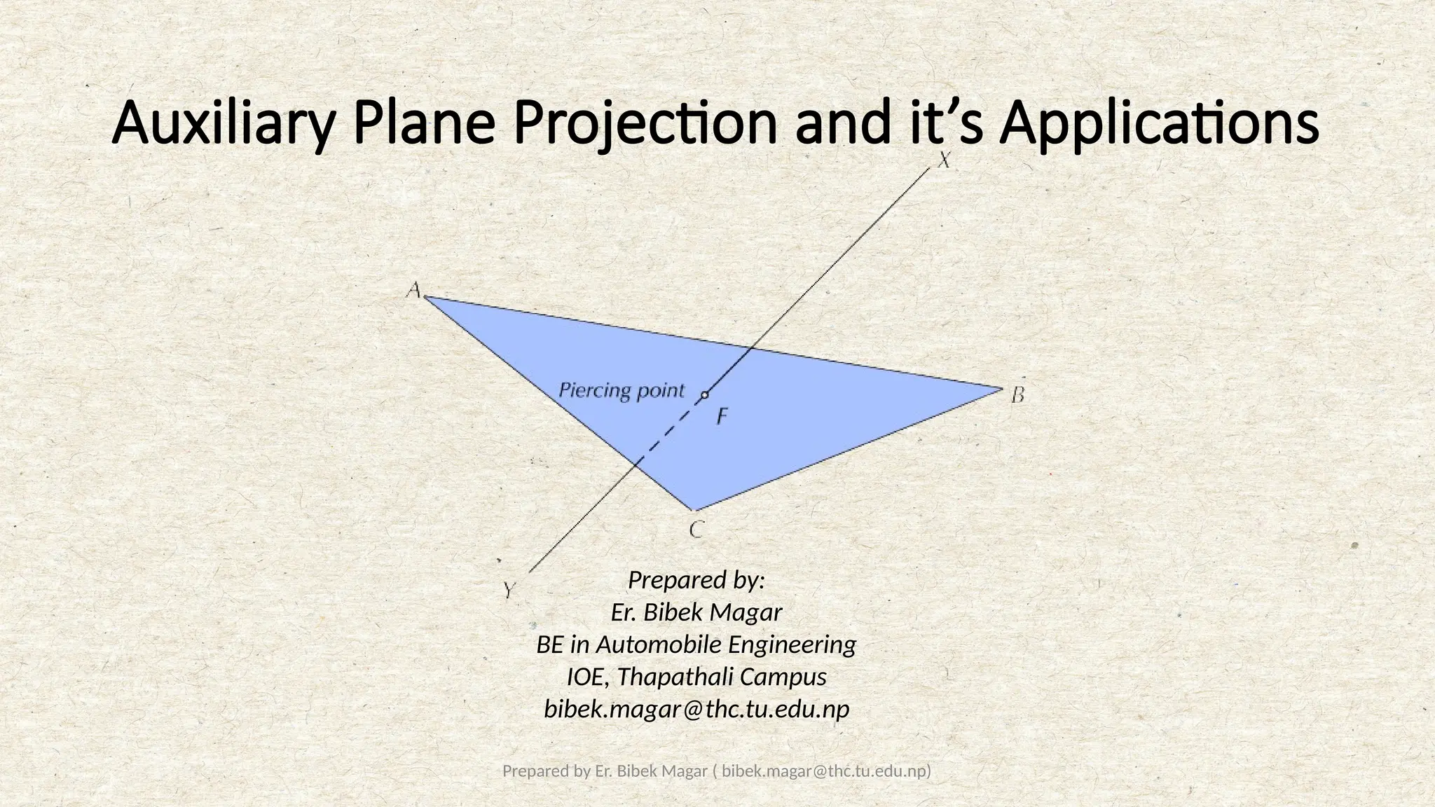
Auxiliary Plane Projection and it’s Applications
Prepared by:
Er. Bibek Magar
BE in Automobile Engineering
IOE, Thapathali Campus
bibek.magar@thc.tu.edu.np
2.
Prepared by Er.Bibek Magar ( bibek.magar@thc.tu.edu.np)
Auxiliary Plane Projection
• The principal planes of projection, that is, the vertical, the horizontal and the profile planes are mutually
perpendicular. The views projected on these principal planes, known as the principal views, are not sufficient
to completely describe those objects that have a number of inclined surfaces in addition to the mutually
perpendicular faces.
• When the principal views are not enough to provide the required information about the true shape of
inclined surfaces of an object, projections on the auxiliary planes, perpendicular to one of the principal
planes of projection and parallel to the inclined surface of the object, are used.
• An auxiliary plane perpendicular to the HP and inclined to the VP is known as an auxiliary vertical plane
(AVP), and one that is perpendicular to the VP and inclined to the HP is known as an auxiliary inclined plane
(AIP).
• The views obtained on auxiliary planes are known as primary auxiliary views. Let us look at how projections
of points are obtained on these auxiliary planes.
3.
Prepared by Er.Bibek Magar ( bibek.magar@thc.tu.edu.np)
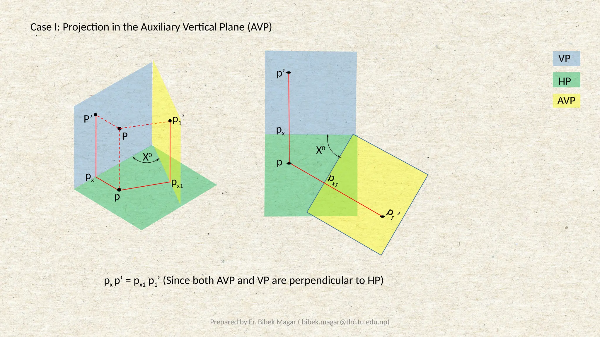
Case I: Projection in the Auxiliary Vertical Plane (AVP)
px p’ = px1 p1’ (Since both AVP and VP are perpendicular to HP)
P
P’
p
X0
p1’
px px1
X0
p’
p
1 ’
px1
px
p
HP
VP
AVP
4.
Prepared by Er.Bibek Magar ( bibek.magar@thc.tu.edu.np)
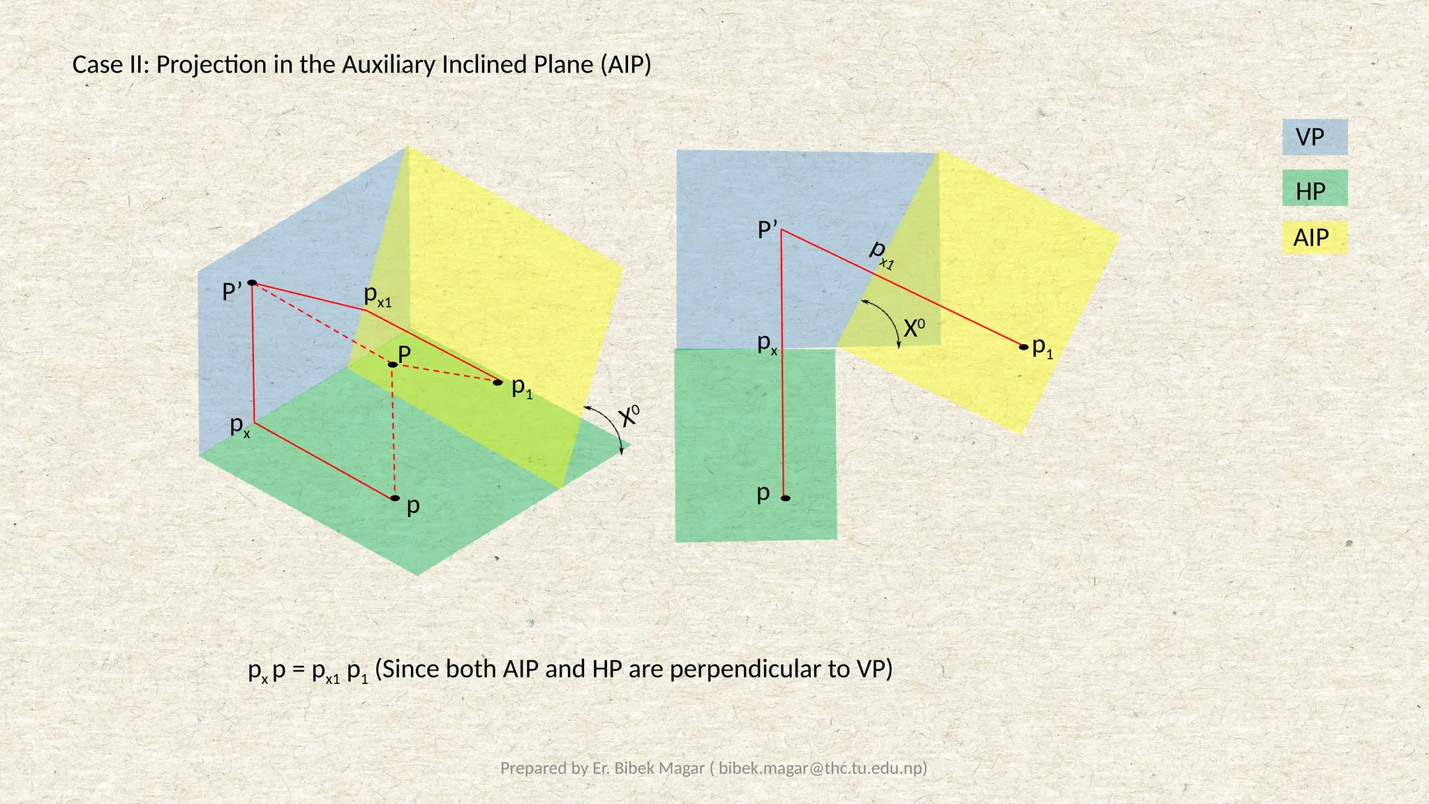
Case II: Projection in the Auxiliary Inclined Plane (AIP)
px p = px1 p1 (Since both AIP and HP are perpendicular to VP)
HP
VP
AIP
X0
X0
P
P’
p
p1
px
px1
P’
p
p1
px
px1
5.
Prepared by Er.Bibek Magar ( bibek.magar@thc.tu.edu.np)
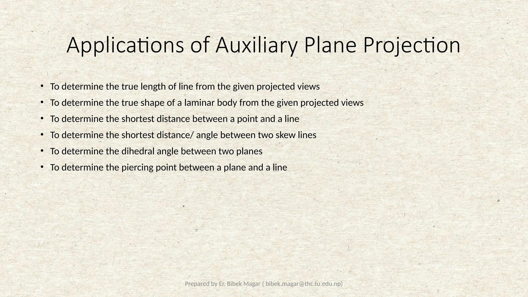
Applications of Auxiliary Plane Projection
• To determine the true length of line from the given projected views
• To determine the true shape of a laminar body from the given projected views
• To determine the shortest distance between a point and a line
• To determine the shortest distance/ angle between two skew lines
• To determine the dihedral angle between two planes
• To determine the piercing point between a plane and a line
6.
Prepared by Er.Bibek Magar ( bibek.magar@thc.tu.edu.np)
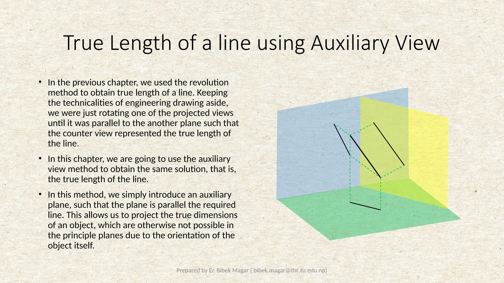
True Length of a line using Auxiliary View
• In the previous chapter, we used the revolution
method to obtain true length of a line. Keeping
the technicalities of engineering drawing aside,
we were just rotating one of the projected views
until it was parallel to the another plane such that
the counter view represented the true length of
the line.
• In this chapter, we are going to use the auxiliary
view method to obtain the same solution, that is,
the true length of the line.
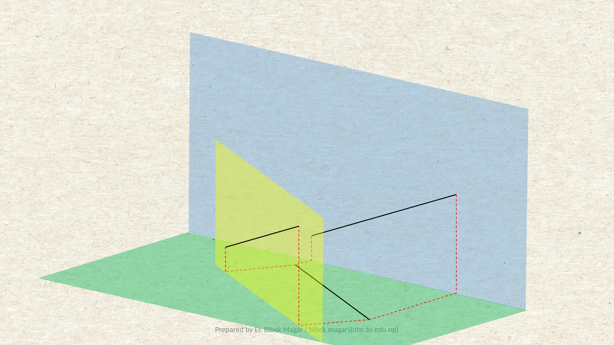
• In this method, we simply introduce an auxiliary
plane, such that the plane is parallel the required
line. This allows us to project the true dimensions
of an object, which are otherwise not possible in
the principle planes due to the orientation of the
object itself.
7.
Prepared by Er.Bibek Magar ( bibek.magar@thc.tu.edu.np)
Solved Examples:
8.
Prepared by Er.Bibek Magar ( bibek.magar@thc.tu.edu.np)
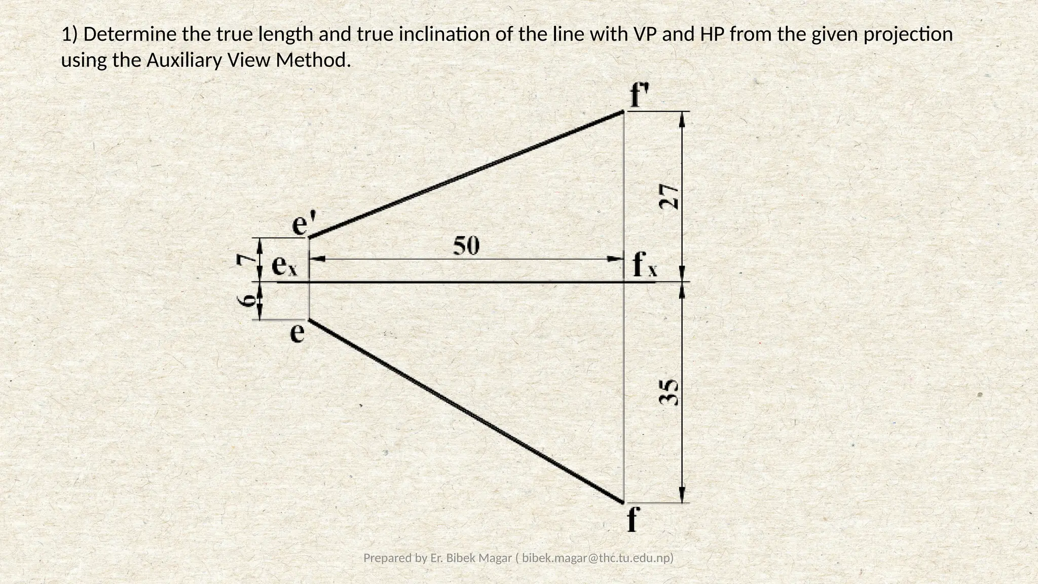
1) Determine the true length and true inclination of the line with VP and HP from the given projection
using the Auxiliary View Method.
2
8
°
6
1
.
1
6
3
7
VP
HP
VP
AIP
f’
e
f
e’
x y
e1
f1
x1
y1
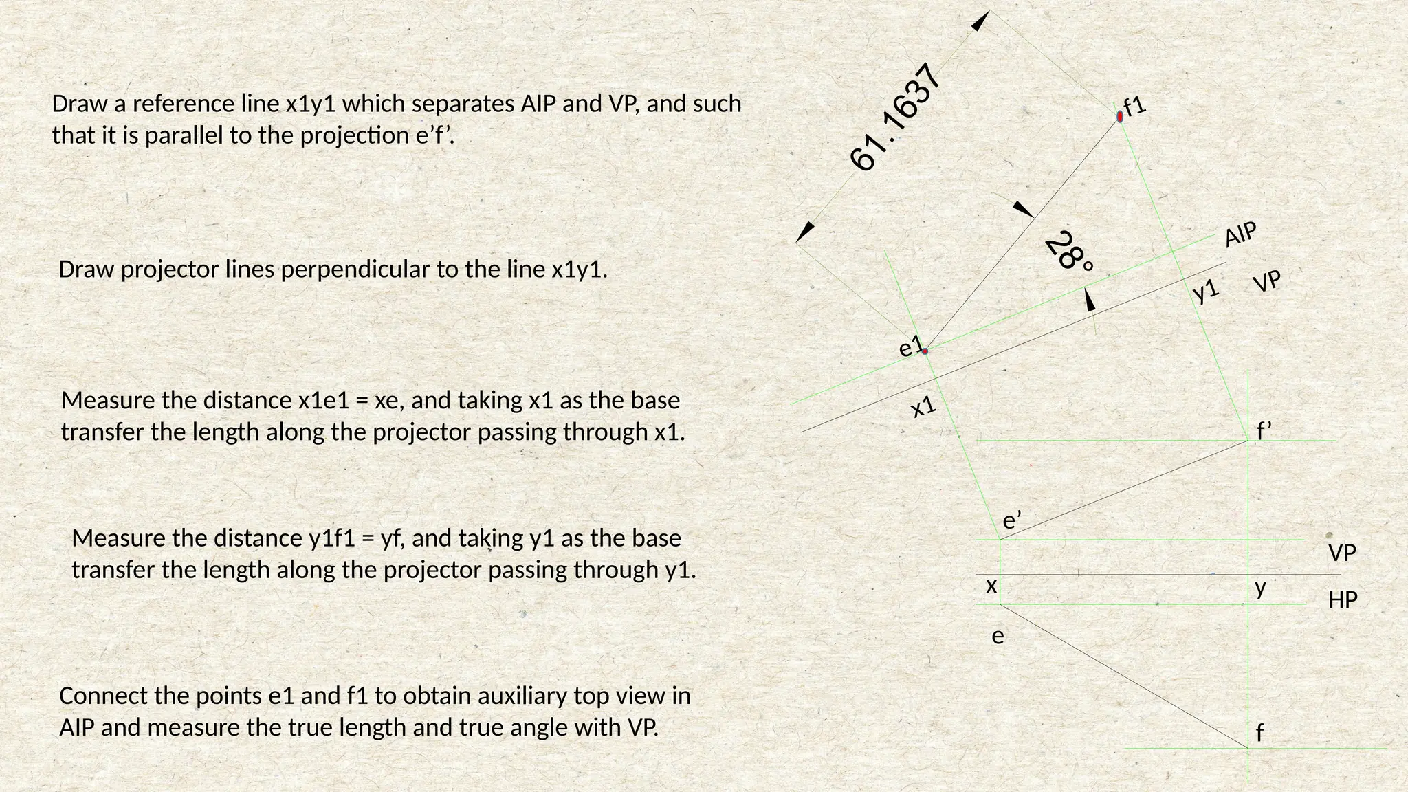
Draw areference line x1y1 which separates AIP and VP, and such
that it is parallel to the projection e’f’.
Draw projector lines perpendicular to the line x1y1.
Measure the distance x1e1 = xe, and taking x1 as the base
transfer the length along the projector passing through x1.
Measure the distance y1f1 = yf, and taking y1 as the base
transfer the length along the projector passing through y1.
Connect the points e1 and f1 to obtain auxiliary top view in
AIP and measure the true length and true angle with VP.
11.
Prepared by Er.Bibek Magar ( bibek.magar@thc.tu.edu.np)
2
8
°
19°
6
1
.
1
6
3
7
AIP
VP
VP
HP
HP
AVP
f1
e1
f’
e’
e
f
x y
x2
e2’
y2
f2’
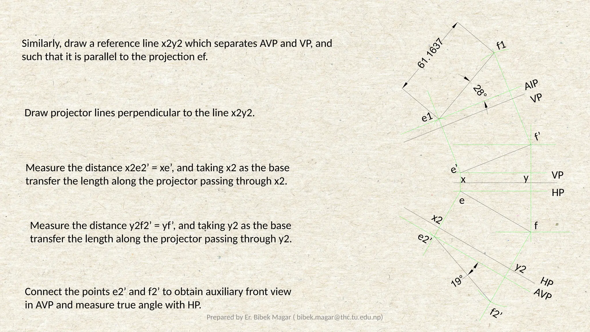
Similarly, draw a reference line x2y2 which separates AVP and VP, and
such that it is parallel to the projection ef.
Draw projector lines perpendicular to the line x2y2.
Measure the distance x2e2’ = xe’, and taking x2 as the base
transfer the length along the projector passing through x2.
Measure the distance y2f2’ = yf’, and taking y2 as the base
transfer the length along the projector passing through y2.
Connect the points e2’ and f2’ to obtain auxiliary front view
in AVP and measure true angle with HP.
12.
Prepared by Er.Bibek Magar ( bibek.magar@thc.tu.edu.np)
Point View of a Line
• In real life, when we observe a linear object perpendicularly, the lateral surface seems to vanish and we see
the top surface of that linear object.
• We use the same principle to obtain a point view of a line.
• In real life we used the real object, that is, the object represented true dimensions. However in the
problems, we are presented with projected views which may not represent the true length of the line.
• So, the first step to obtain the point view of a line, we must obtain the true length of the line in one of the
projected views.
• Then, we introduce an auxiliary plane which is perpendicular to the line and the projection of the line in that
plane will be represented by a point.
13.
Prepared by Er.Bibek Magar ( bibek.magar@thc.tu.edu.np)
VP
HP
e’
f’
e
f
AVP
x
AVP
AP1
f1’
e1’
f1, (e1)
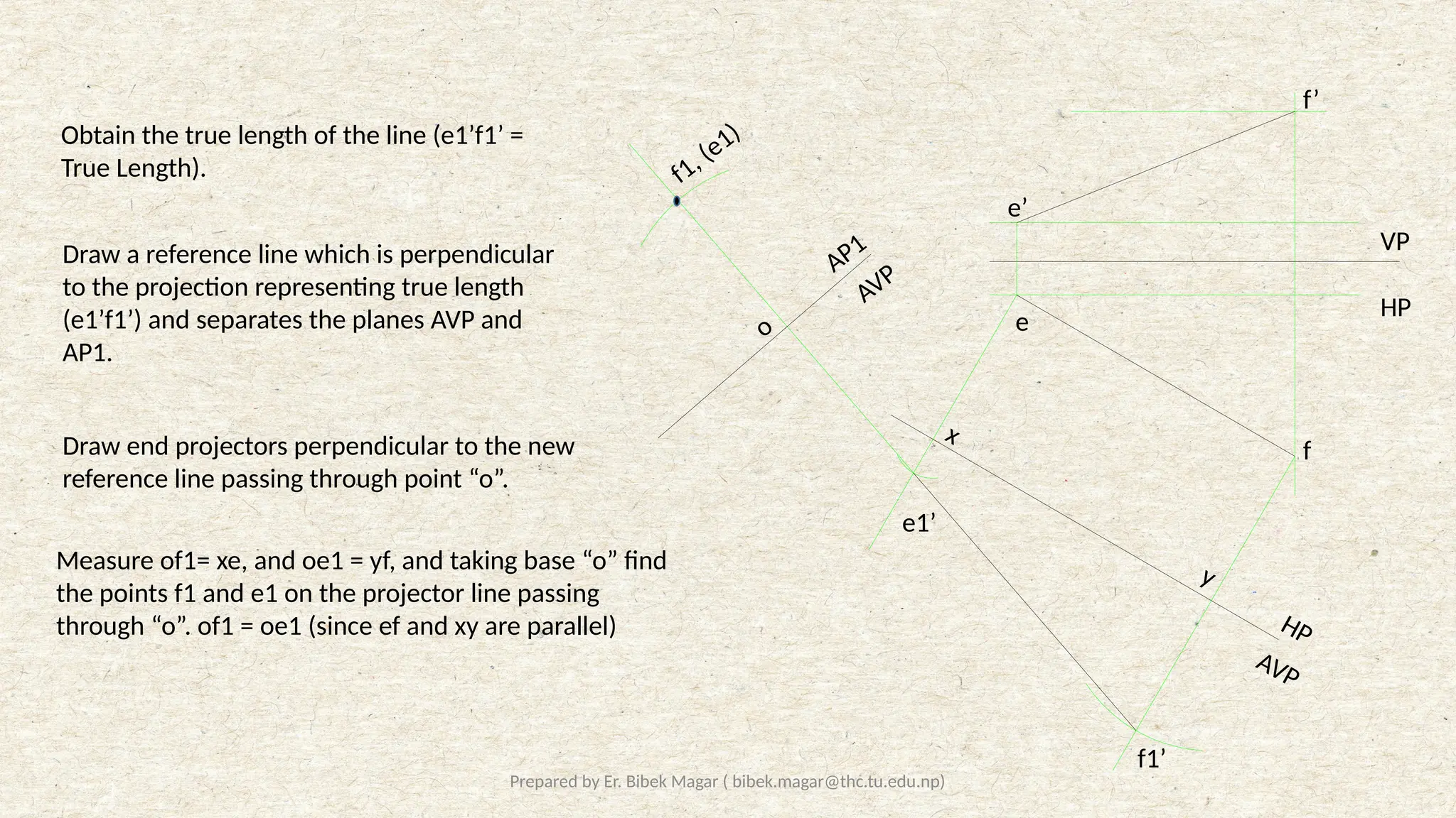
Obtain the true length of the line (e1’f1’ =
True Length).
Draw a reference line which is perpendicular
to the projection representing true length
(e1’f1’) and separates the planes AVP and
AP1.
HP
y
o
Measure of1= xe, and oe1 = yf, and taking base “o” find
the points f1 and e1 on the projector line passing
through “o”. of1 = oe1 (since ef and xy are parallel)
Draw end projectors perpendicular to the new
reference line passing through point “o”.
14.
Prepared by Er.Bibek Magar ( bibek.magar@thc.tu.edu.np)
Edge View of a Plane
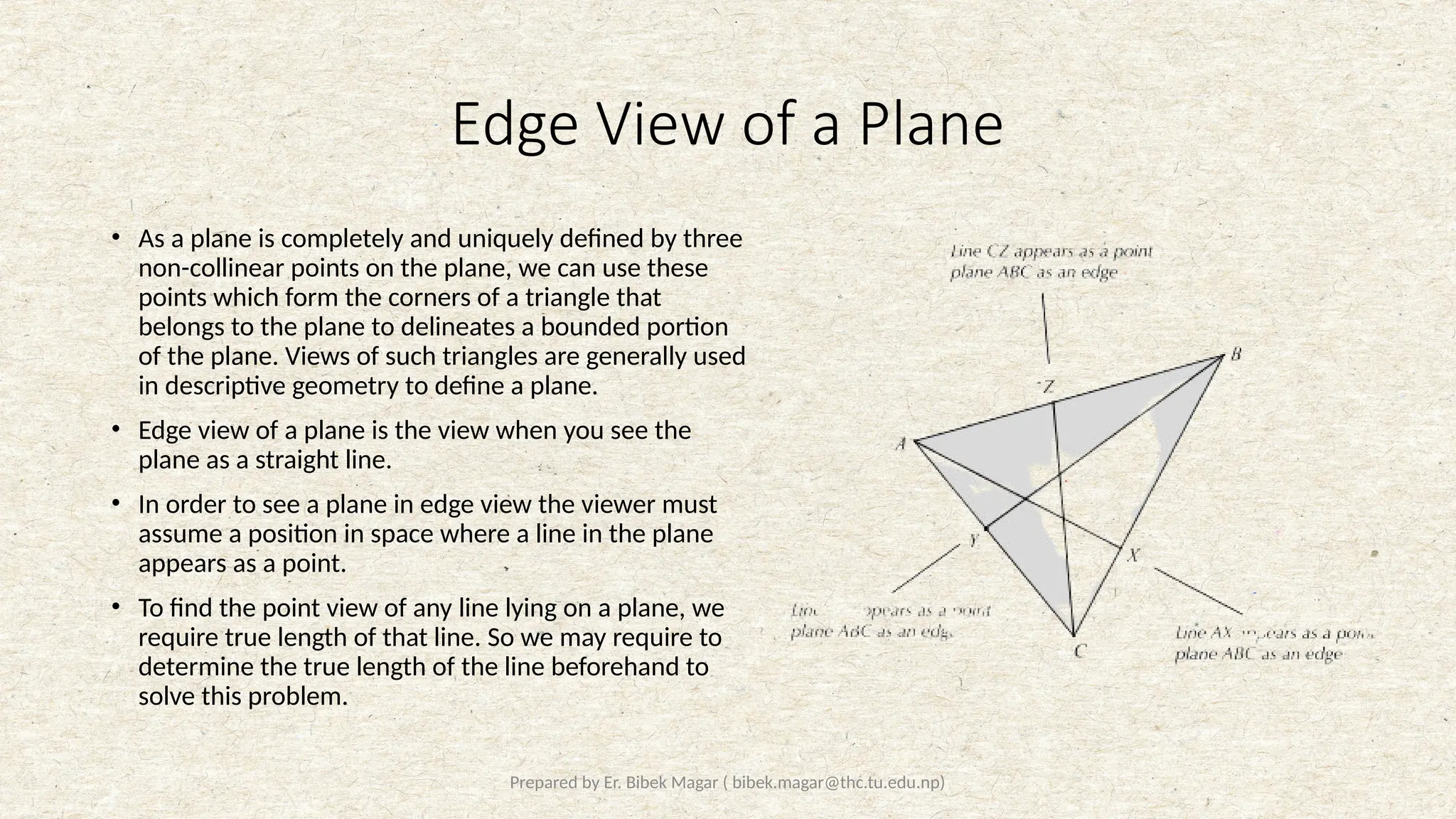
• As a plane is completely and uniquely defined by three
non-collinear points on the plane, we can use these
points which form the corners of a triangle that
belongs to the plane to delineates a bounded portion
of the plane. Views of such triangles are generally used
in descriptive geometry to define a plane.
• Edge view of a plane is the view when you see the
plane as a straight line.
• In order to see a plane in edge view the viewer must
assume a position in space where a line in the plane
appears as a point.
• To find the point view of any line lying on a plane, we
require true length of that line. So we may require to
determine the true length of the line beforehand to
solve this problem.
15.
Prepared by Er.Bibek Magar ( bibek.magar@thc.tu.edu.np)
General Steps to Obtain Edge View of a Plane
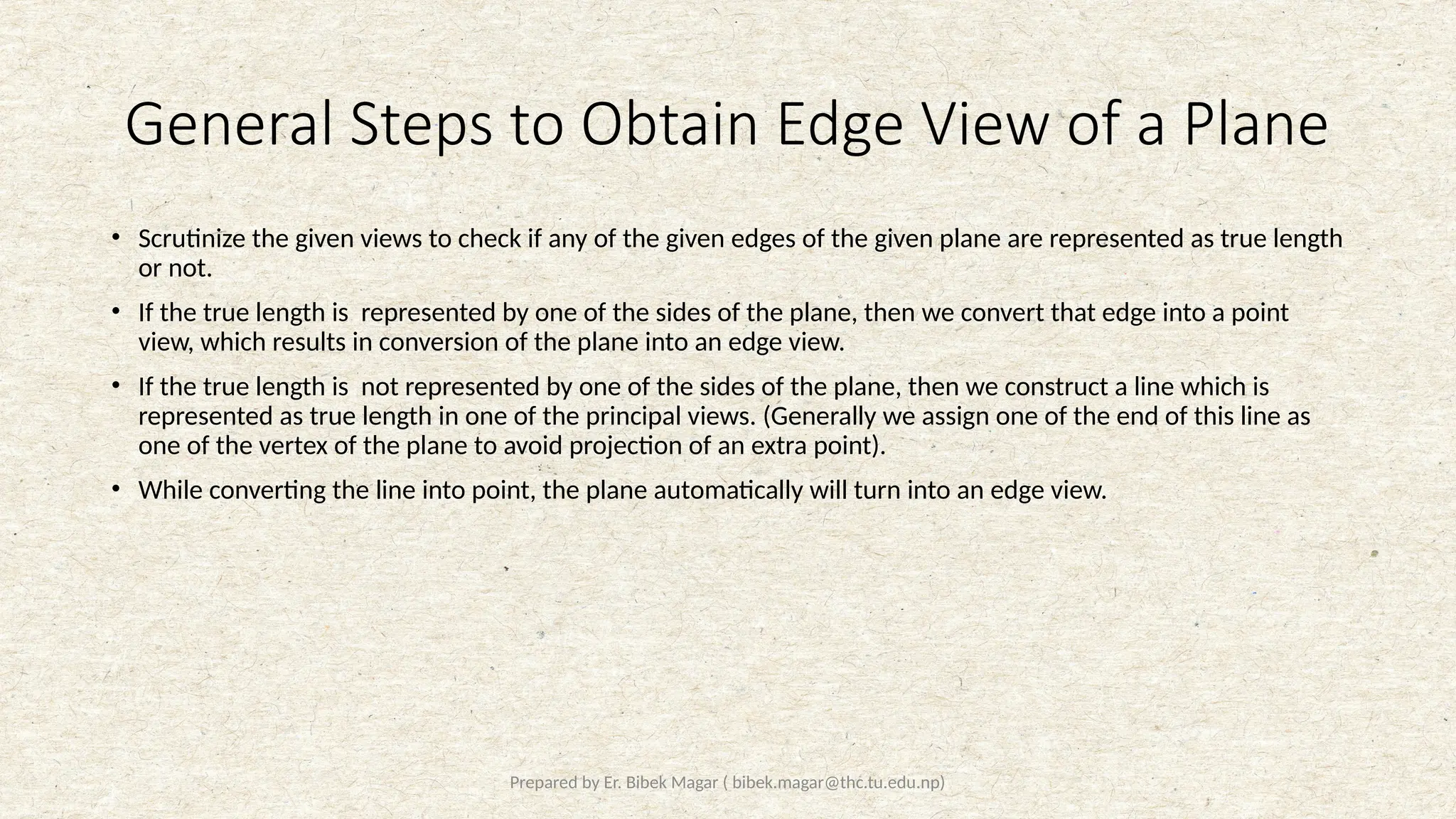
• Scrutinize the given views to check if any of the given edges of the given plane are represented as true length
or not.
• If the true length is represented by one of the sides of the plane, then we convert that edge into a point
view, which results in conversion of the plane into an edge view.
• If the true length is not represented by one of the sides of the plane, then we construct a line which is
represented as true length in one of the principal views. (Generally we assign one of the end of this line as
one of the vertex of the plane to avoid projection of an extra point).
• While converting the line into point, the plane automatically will turn into an edge view.
16.
Prepared by Er.Bibek Magar ( bibek.magar@thc.tu.edu.np)
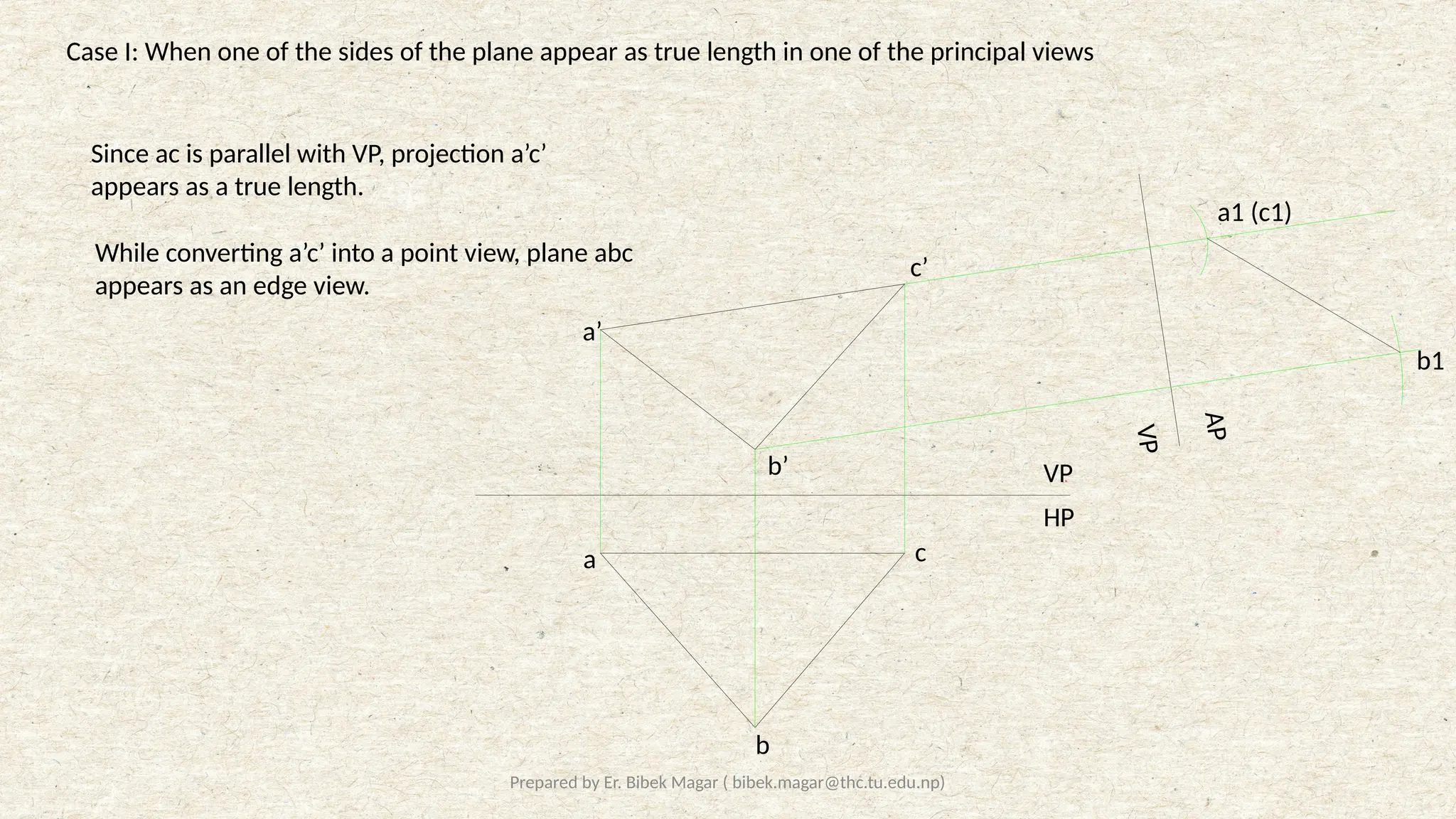
Case I: When one of the sides of the plane appear as true length in one of the principal views
VP
HP
a
b
c
a’
b’
c’
a1 (c1)
b1
Since ac is parallel with VP, projection a’c’
appears as a true length.
While converting a’c’ into a point view, plane abc
appears as an edge view.
A
P
V
P
17.
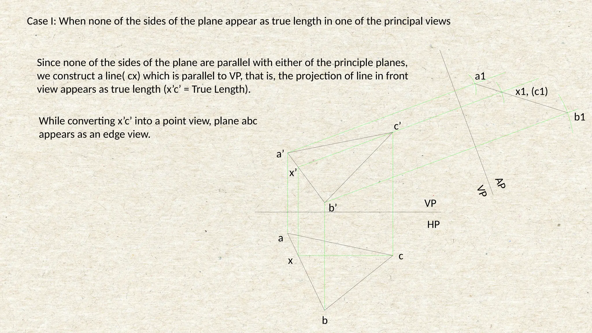
Case I: Whennone of the sides of the plane appear as true length in one of the principal views
Since none of the sides of the plane are parallel with either of the principle planes,
we construct a line( cx) which is parallel to VP, that is, the projection of line in front
view appears as true length (x’c’ = True Length).
a
b
c
x
b’
a’
c’
x’
x1, (c1)
a1
b1
HP
VP
A
P
V
P
While converting x’c’ into a point view, plane abc
appears as an edge view.
18.
Prepared by Er.Bibek Magar ( bibek.magar@thc.tu.edu.np)
Alternately,
a’
b’
c’
y’
a
b
c
y
c1’
b1’
a1’, (y1’)
HP
VP
A
P
1
H
P
19.
Prepared by Er.Bibek Magar ( bibek.magar@thc.tu.edu.np)
Shortest Distance Between a Point and a Line
• To determine the shortest distance between a point and a line, we convert the one of the projected view
into it’s point view.
• While converting the line into it’s point view, we introduce various auxiliary planes, and the point is shifted
accordingly until the projection of the line is converted into a point.
• Finally the given point and the point view of the line is connected and the distance is measured.
20.
Prepared by Er.Bibek Magar ( bibek.magar@thc.tu.edu.np)
Solved Examples:
21.
Prepared by Er.Bibek Magar ( bibek.magar@thc.tu.edu.np)
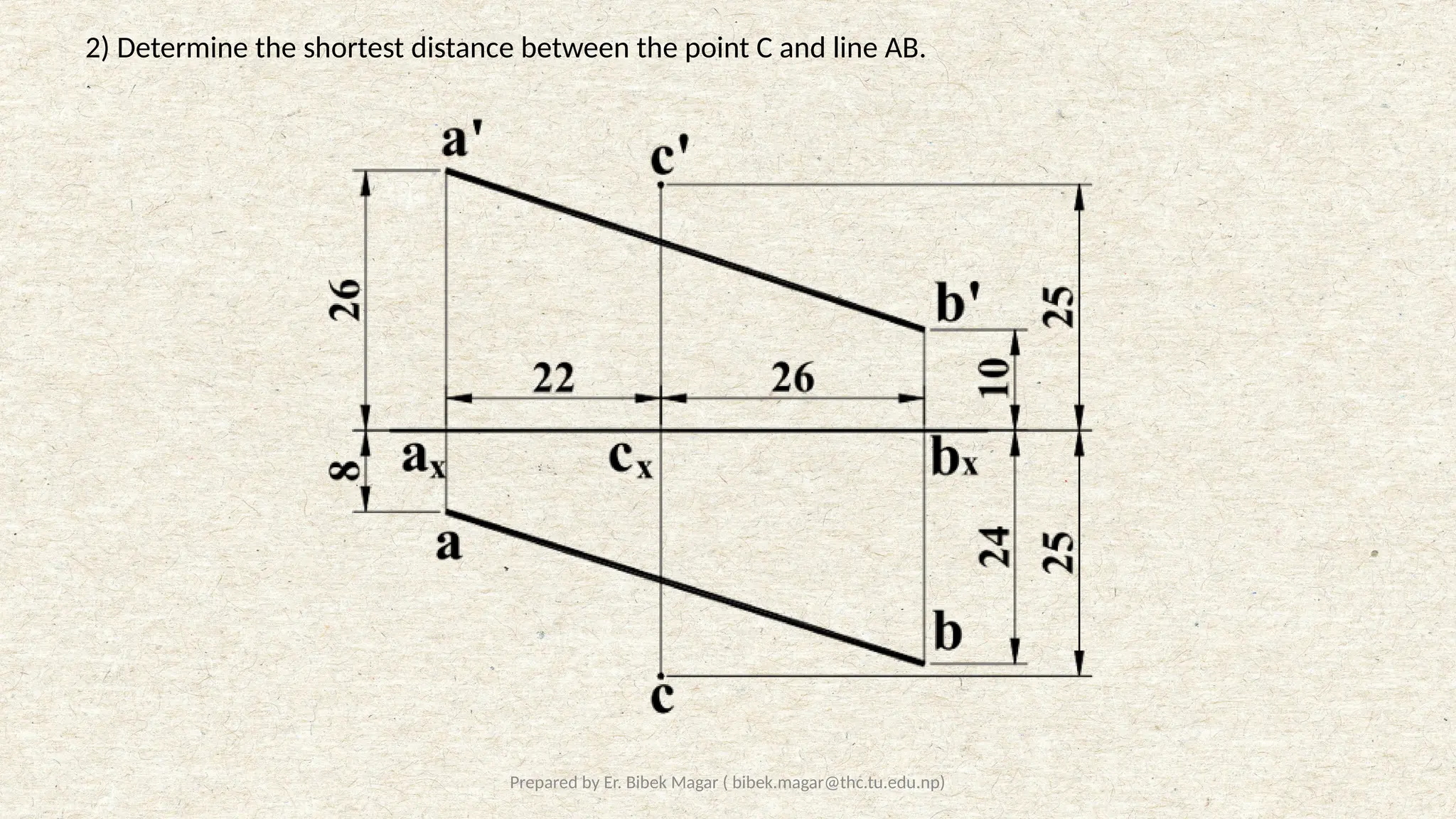
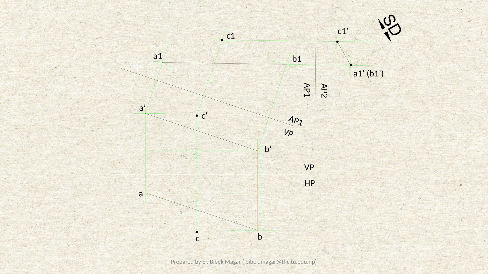
2) Determine the shortest distance between the point C and line AB.
22.
Prepared by Er.Bibek Magar ( bibek.magar@thc.tu.edu.np)
S
D
VP
HP
VP
AP1
AP1
AP2
a’
b’
c’
b
a
c
b1
a1
c1
a1’ (b1’)
c1’
23.
Prepared by Er.Bibek Magar ( bibek.magar@thc.tu.edu.np)
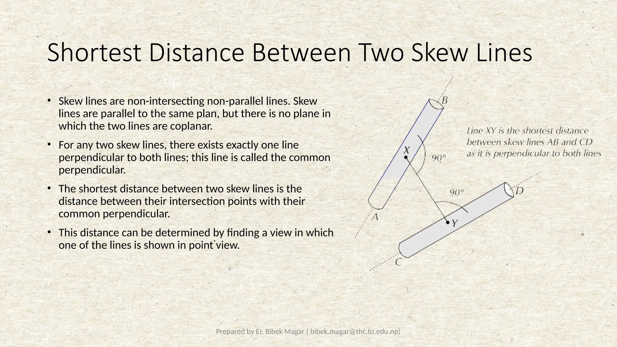
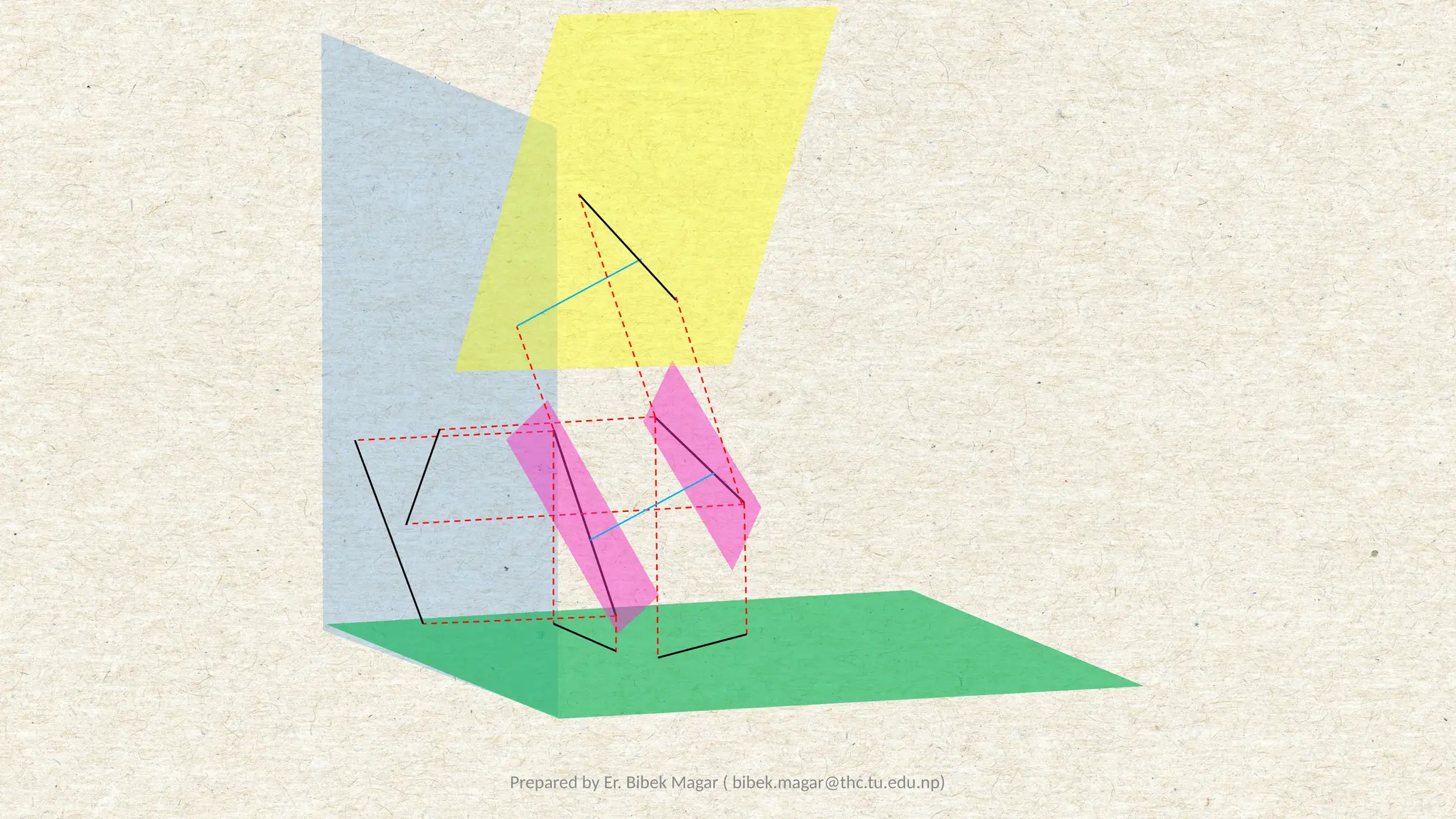
Shortest Distance Between Two Skew Lines
• Skew lines are non-intersecting non-parallel lines. Skew
lines are parallel to the same plan, but there is no plane in
which the two lines are coplanar.
• For any two skew lines, there exists exactly one line
perpendicular to both lines; this line is called the common
perpendicular.
• The shortest distance between two skew lines is the
distance between their intersection points with their
common perpendicular.
• This distance can be determined by finding a view in which
one of the lines is shown in point view.
Prepared by Er.Bibek Magar ( bibek.magar@thc.tu.edu.np)
Solved Examples:
26.
Prepared by Er.Bibek Magar ( bibek.magar@thc.tu.edu.np)
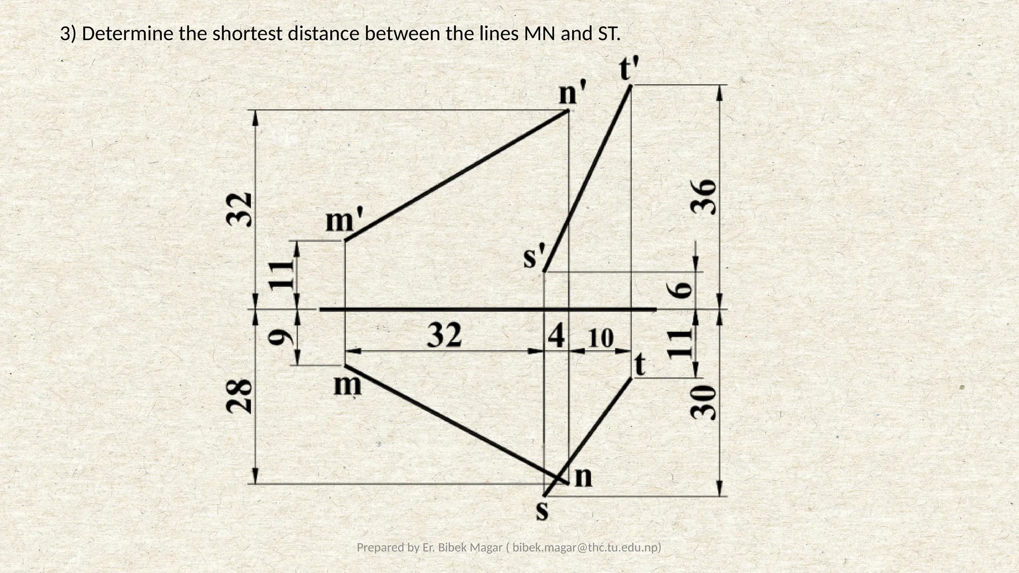
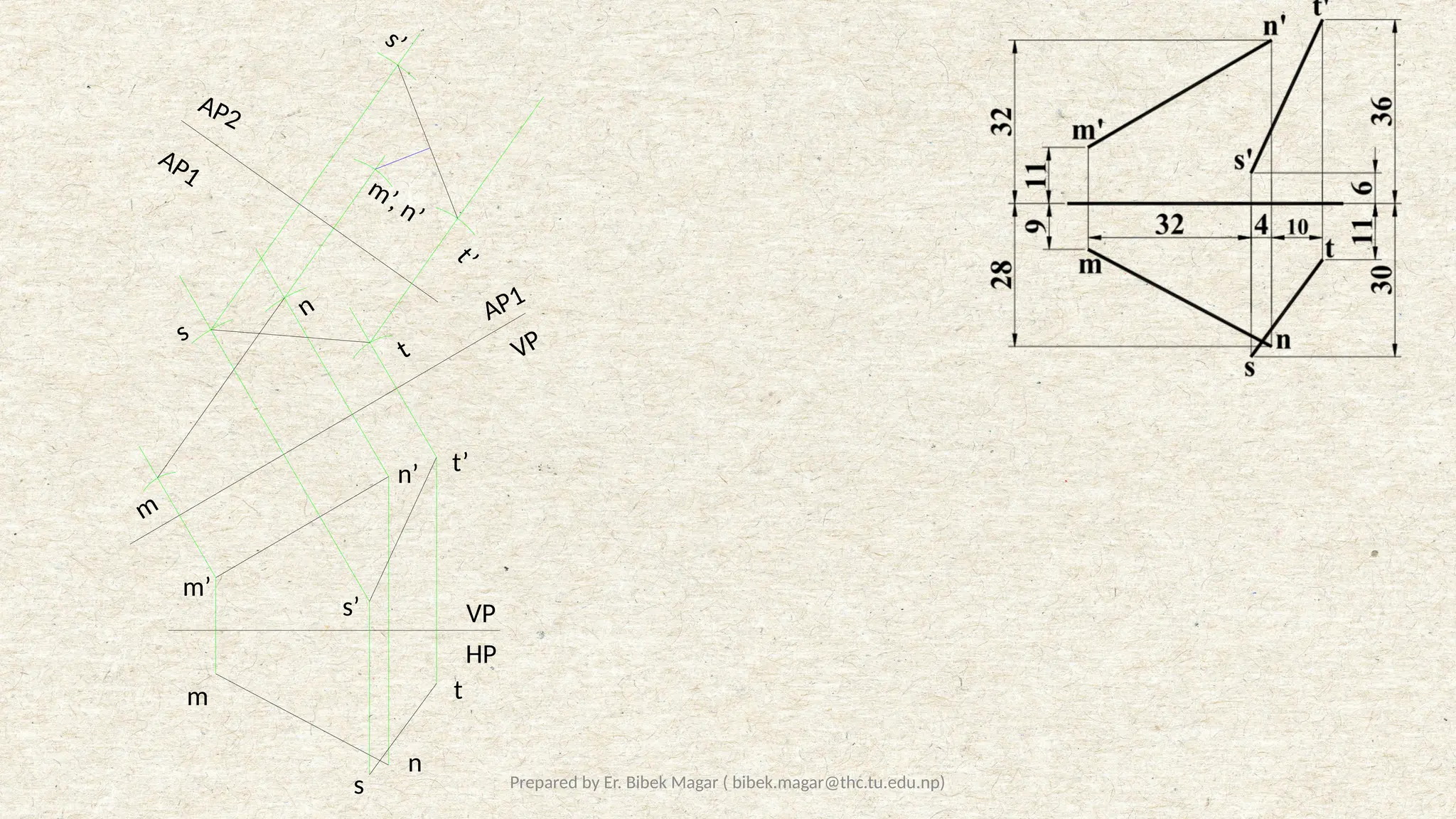
3) Determine the shortest distance between the lines MN and ST.
27.
Prepared by Er.Bibek Magar ( bibek.magar@thc.tu.edu.np)
HP
VP
m
n
s
t
m’
s’
t’
n’
AP1
VP
m’, n’
t
s’
t
’
m
n
s
AP1
AP2
28.
Prepared by Er.Bibek Magar ( bibek.magar@thc.tu.edu.np)
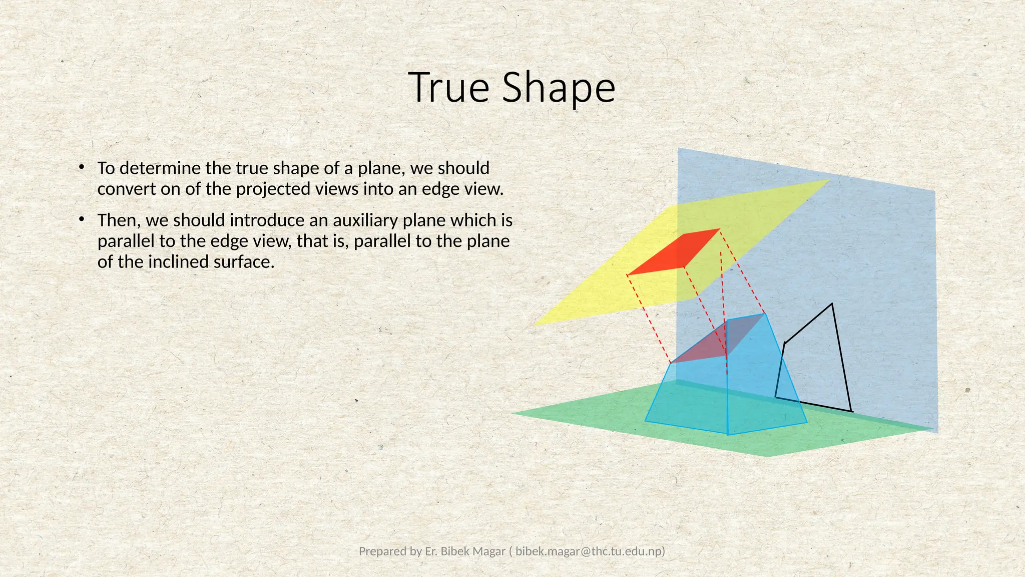
True Shape
• To determine the true shape of a plane, we should
convert on of the projected views into an edge view.
• Then, we should introduce an auxiliary plane which is
parallel to the edge view, that is, parallel to the plane
of the inclined surface.
29.
Prepared by Er.Bibek Magar ( bibek.magar@thc.tu.edu.np)
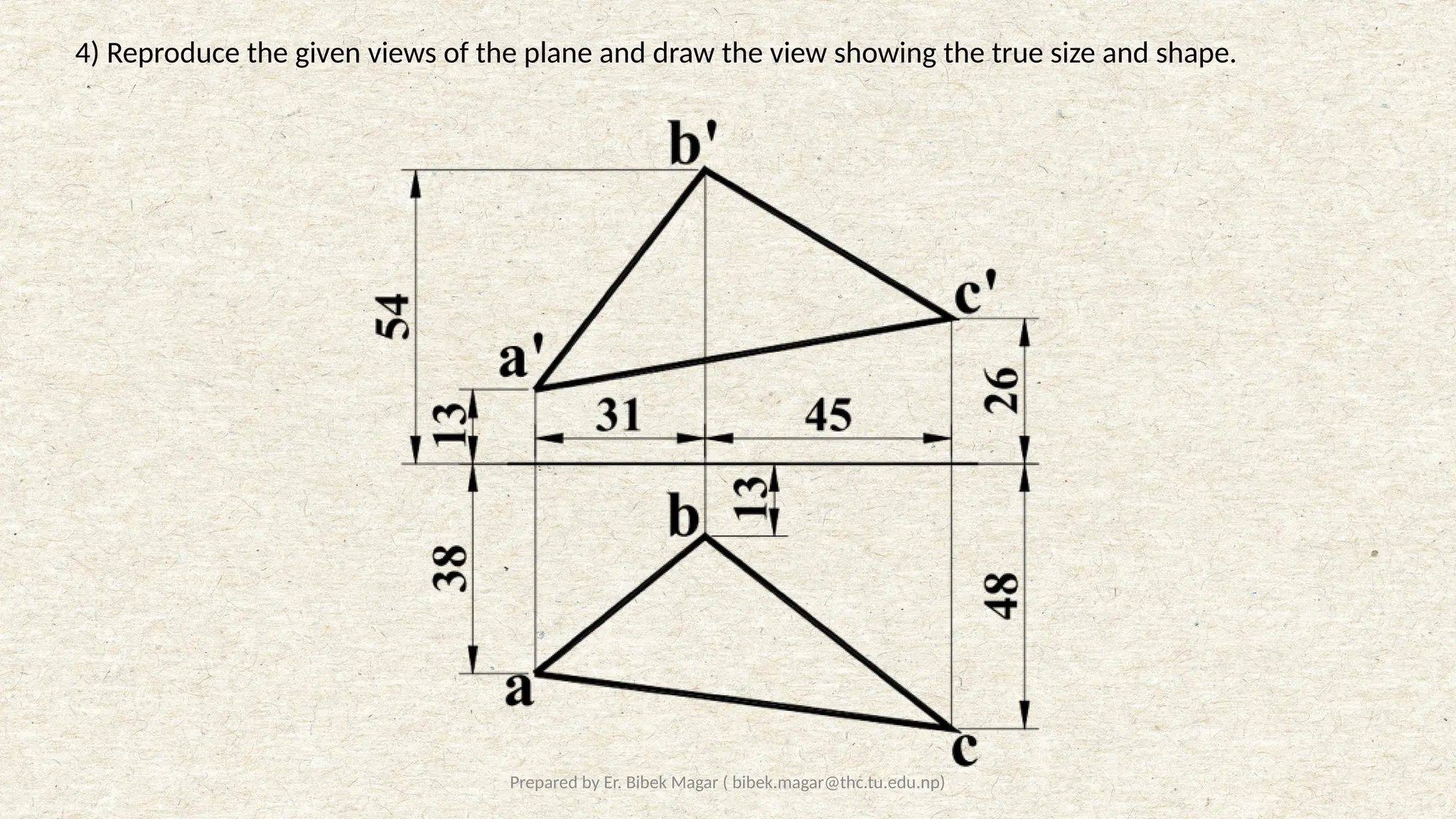
4) Reproduce the given views of the plane and draw the view showing the true size and shape.
30.
Prepared by Er.Bibek Magar ( bibek.magar@thc.tu.edu.np)
VP
HP
b
a c
a’
b’
c’
a1’
b1’
x1’, (c1’)
a1
b1
c1
x
x’
TS
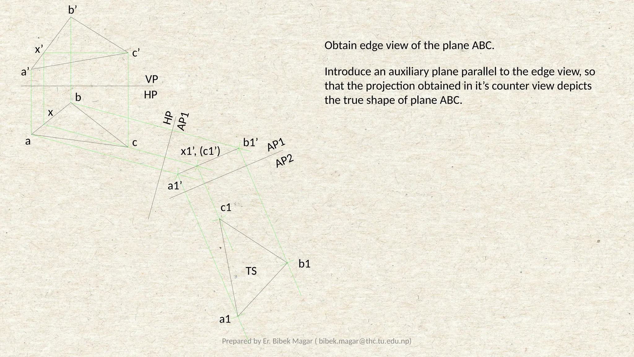
Obtain edge view of the plane ABC.
Introduce an auxiliary plane parallel to the edge view, so
that the projection obtained in it’s counter view depicts
the true shape of plane ABC.
H
P
A
P
1
AP1
AP2
31.
Prepared by Er.Bibek Magar ( bibek.magar@thc.tu.edu.np)
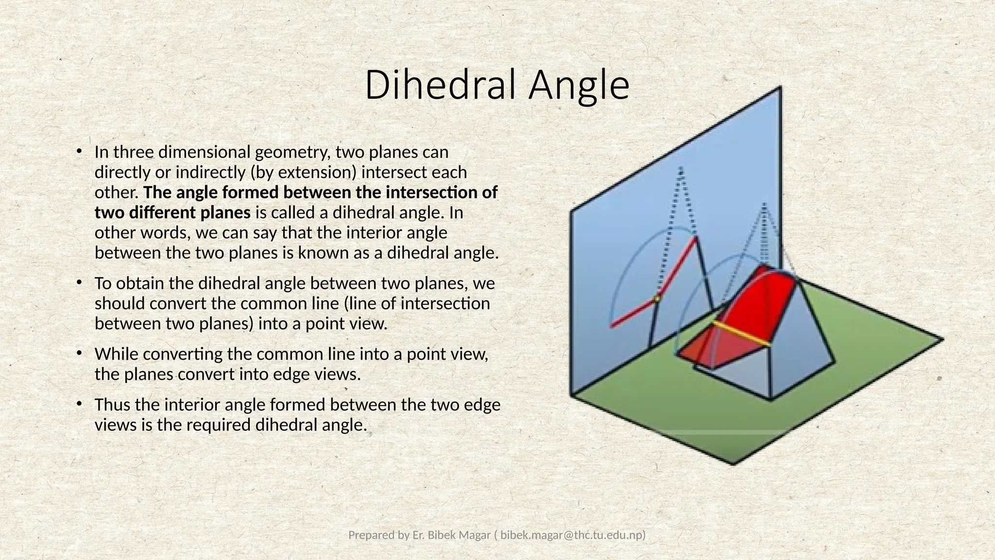
Dihedral Angle
• In three dimensional geometry, two planes can
directly or indirectly (by extension) intersect each
other. The angle formed between the intersection of
two different planes is called a dihedral angle. In
other words, we can say that the interior angle
between the two planes is known as a dihedral angle.
• To obtain the dihedral angle between two planes, we
should convert the common line (line of intersection
between two planes) into a point view.
• While converting the common line into a point view,
the planes convert into edge views.
• Thus the interior angle formed between the two edge
views is the required dihedral angle.
32.
Prepared by Er.Bibek Magar ( bibek.magar@thc.tu.edu.np)
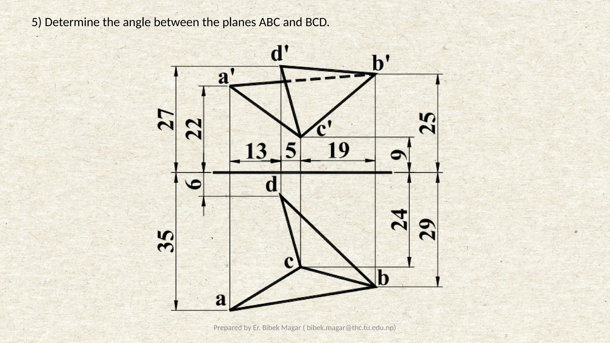
5) Determine the angle between the planes ABC and BCD.
33.
Prepared by Er.Bibek Magar ( bibek.magar@thc.tu.edu.np)
77°
VP
HP
VP
AP1
AP1
AP2
d1’
a
b
c
d
a’
b’
c’
d’
a1
b1
c1
d1
c1’, (b1’)
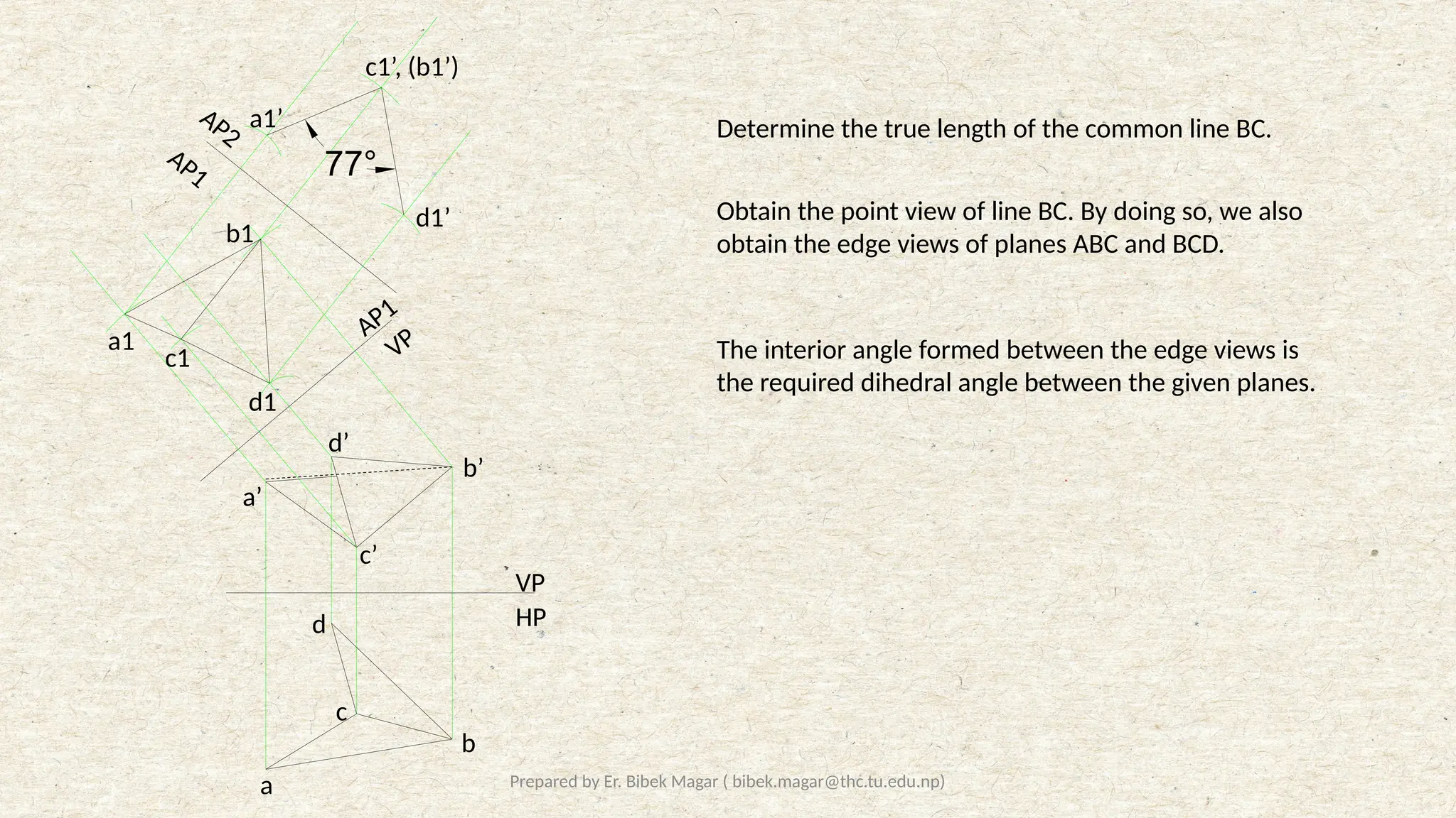
a1’ Determine the true length of the common line BC.
Obtain the point view of line BC. By doing so, we also
obtain the edge views of planes ABC and BCD.
The interior angle formed between the edge views is
the required dihedral angle between the given planes.
34.
Prepared by Er.Bibek Magar ( bibek.magar@thc.tu.edu.np)
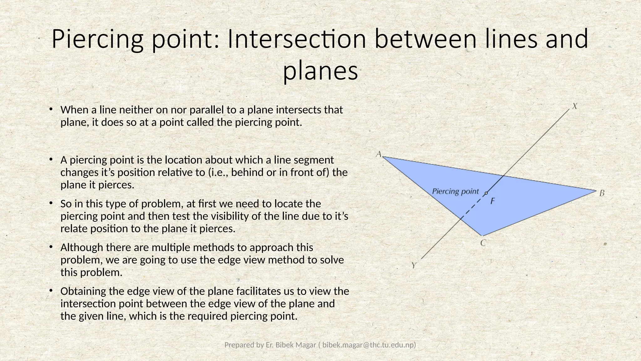
Piercing point: Intersection between lines and
planes
• When a line neither on nor parallel to a plane intersects that
plane, it does so at a point called the piercing point.
• A piercing point is the location about which a line segment
changes it’s position relative to (i.e., behind or in front of) the
plane it pierces.
• So in this type of problem, at first we need to locate the
piercing point and then test the visibility of the line due to it’s
relate position to the plane it pierces.
• Although there are multiple methods to approach this
problem, we are going to use the edge view method to solve
this problem.
• Obtaining the edge view of the plane facilitates us to view the
intersection point between the edge view of the plane and
the given line, which is the required piercing point.
35.
Prepared by Er.Bibek Magar ( bibek.magar@thc.tu.edu.np)
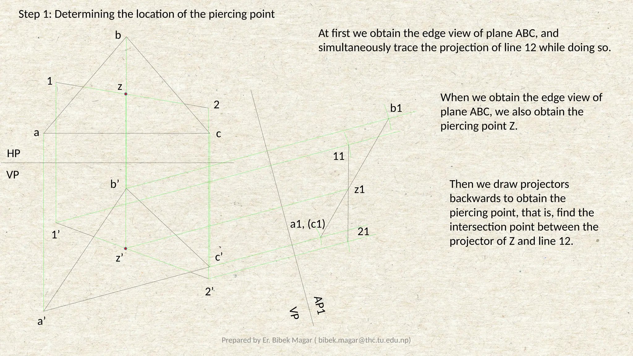
Step 1: Determining the location of the piercing point
VP
HP
V
P
A
P
1
a
b
c
a’
b’
c’
a1, (c1)
b1
1
2
2’
1’
11
21
At first we obtain the edge view of plane ABC, and
simultaneously trace the projection of line 12 while doing so.
When we obtain the edge view of
plane ABC, we also obtain the
piercing point Z.
z
z’
z1 Then we draw projectors
backwards to obtain the
piercing point, that is, find the
intersection point between the
projector of Z and line 12.
36.
Prepared by Er.Bibek Magar ( bibek.magar@thc.tu.edu.np)
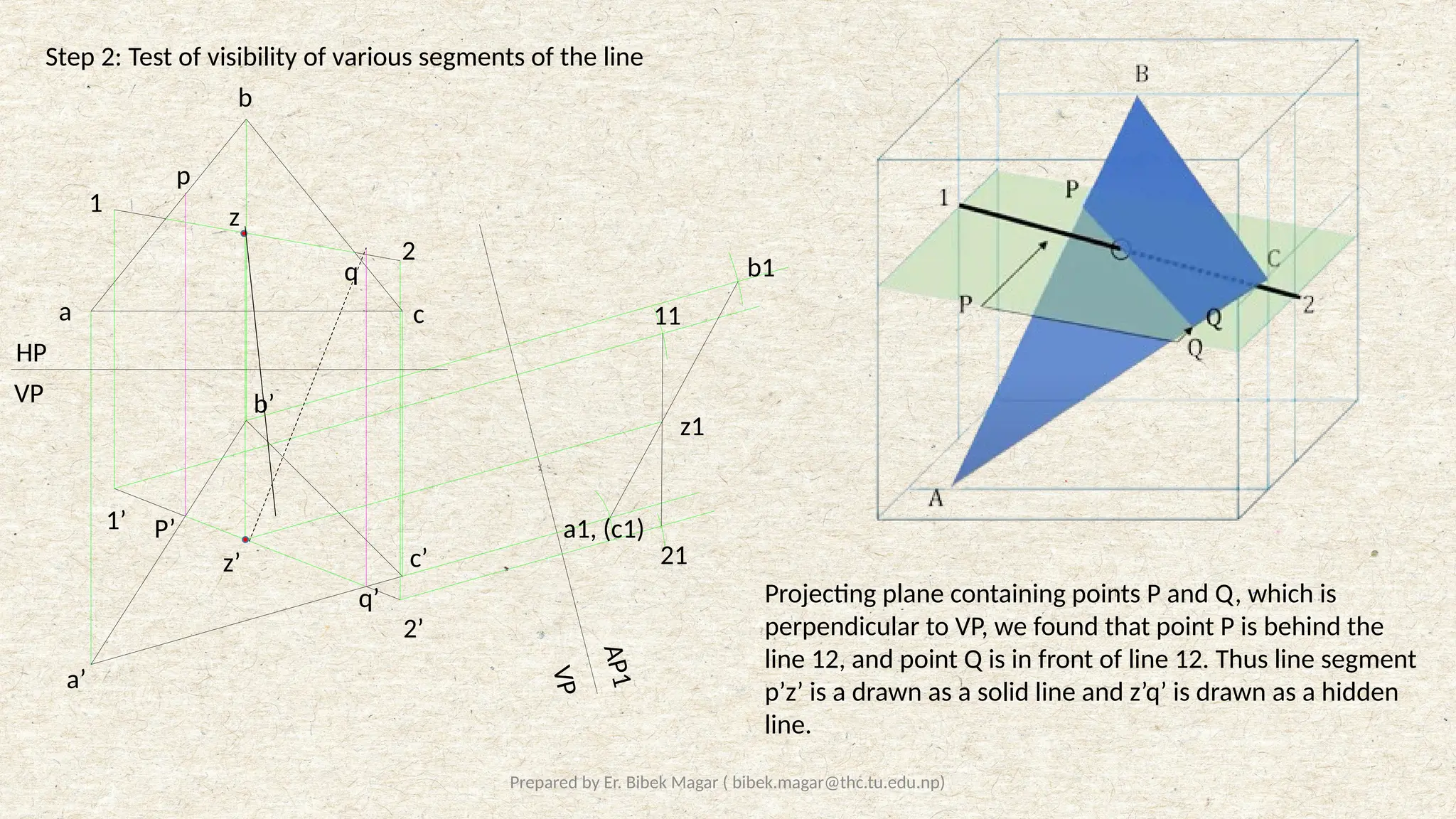
Step 2: Test of visibility of various segments of the line
HP
VP
V
P
A
P
1
b
a c
a’
b’
c’
a1, (c1)
b1
11
21
1
2
1’
2’
z1
z’
z
p
q
P’
q’ Projecting plane containing points P and Q, which is
perpendicular to VP, we found that point P is behind the
line 12, and point Q is in front of line 12. Thus line segment
p’z’ is a drawn as a solid line and z’q’ is drawn as a hidden
line.
37.
Prepared by Er.Bibek Magar ( bibek.magar@thc.tu.edu.np)
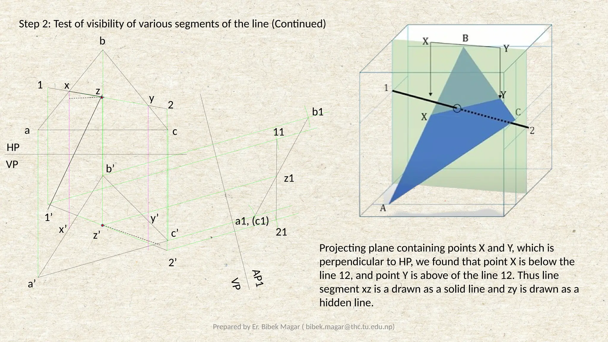
Step 2: Test of visibility of various segments of the line (Continued)
HP
VP
V
P
A
P
1
b
a c
a’
b’
c’
a1, (c1)
b1
11
21
1
2
1’
2’
z1
z’
z
x
y
x’
y’
Projecting plane containing points X and Y, which is
perpendicular to HP, we found that point X is below the
line 12, and point Y is above of the line 12. Thus line
segment xz is a drawn as a solid line and zy is drawn as a
hidden line.
38.
Prepared by Er.Bibek Magar ( bibek.magar@thc.tu.edu.np)
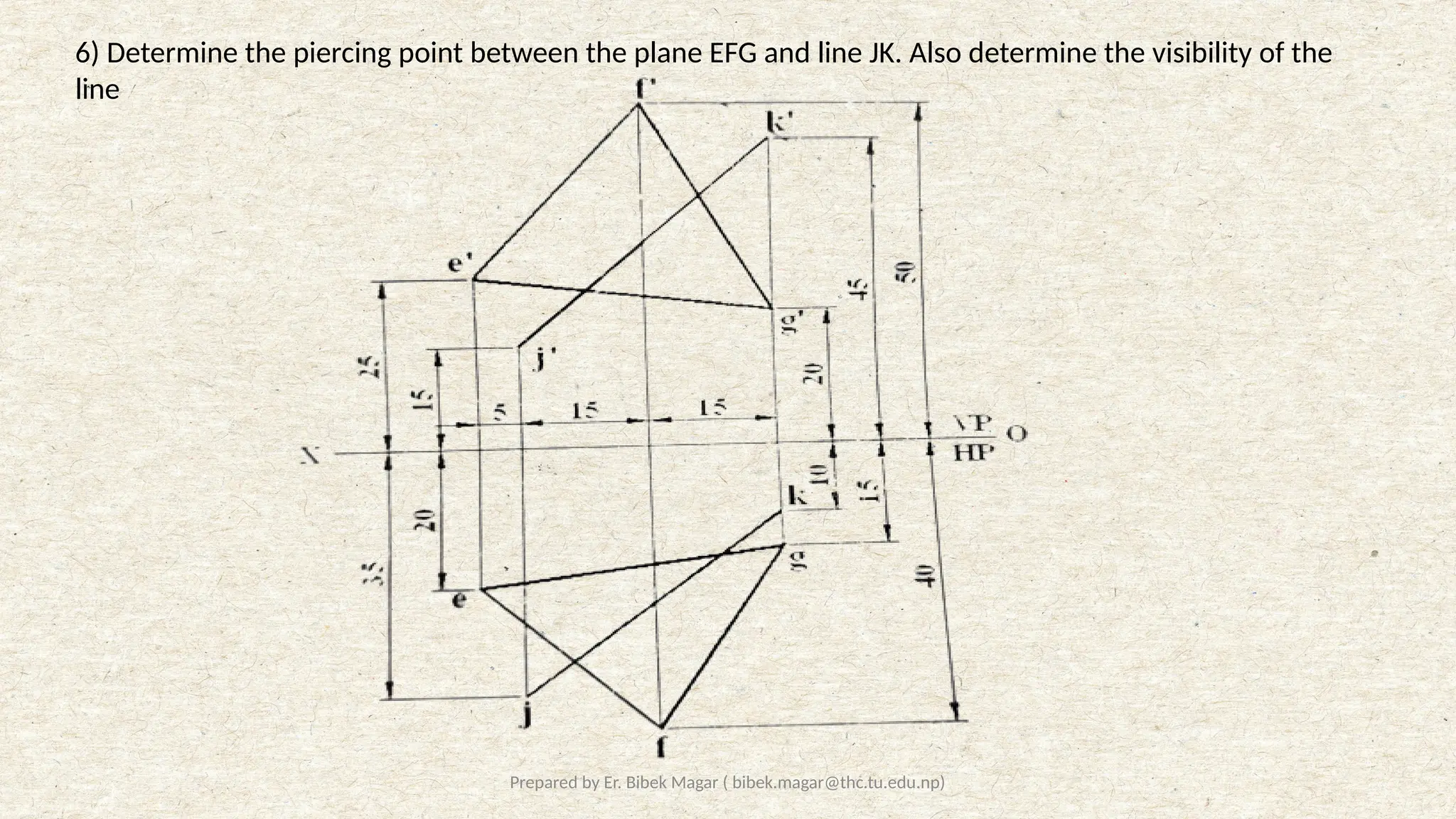
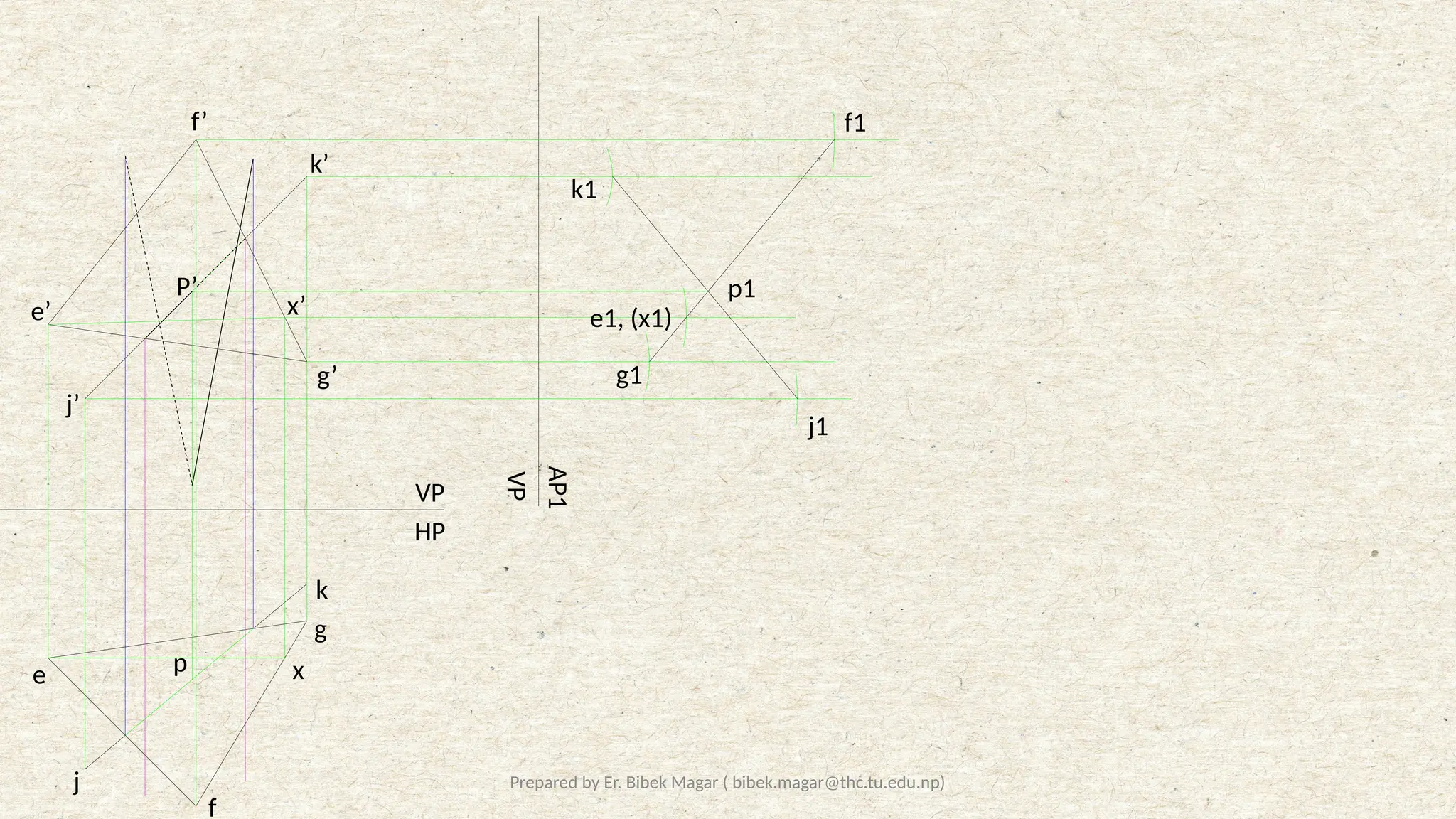
6) Determine the piercing point between the plane EFG and line JK. Also determine the visibility of the
line
39.
Prepared by Er.Bibek Magar ( bibek.magar@thc.tu.edu.np)
VP
HP
VP
AP1
e
f
g
j
k
e’
f’
g’
j’
k’
x’
x
e1, (x1)
f1
g1
j1
k1
p1
P’
p


![8. Auxilary Projections with example [Repaired].pptx](https://cdn.slidesharecdn.com/ss_thumbnails/8-240304062220-18bbd917-thumbnail.jpg?width=640&height=640&fit=bounds)


