Downloaded 25 times


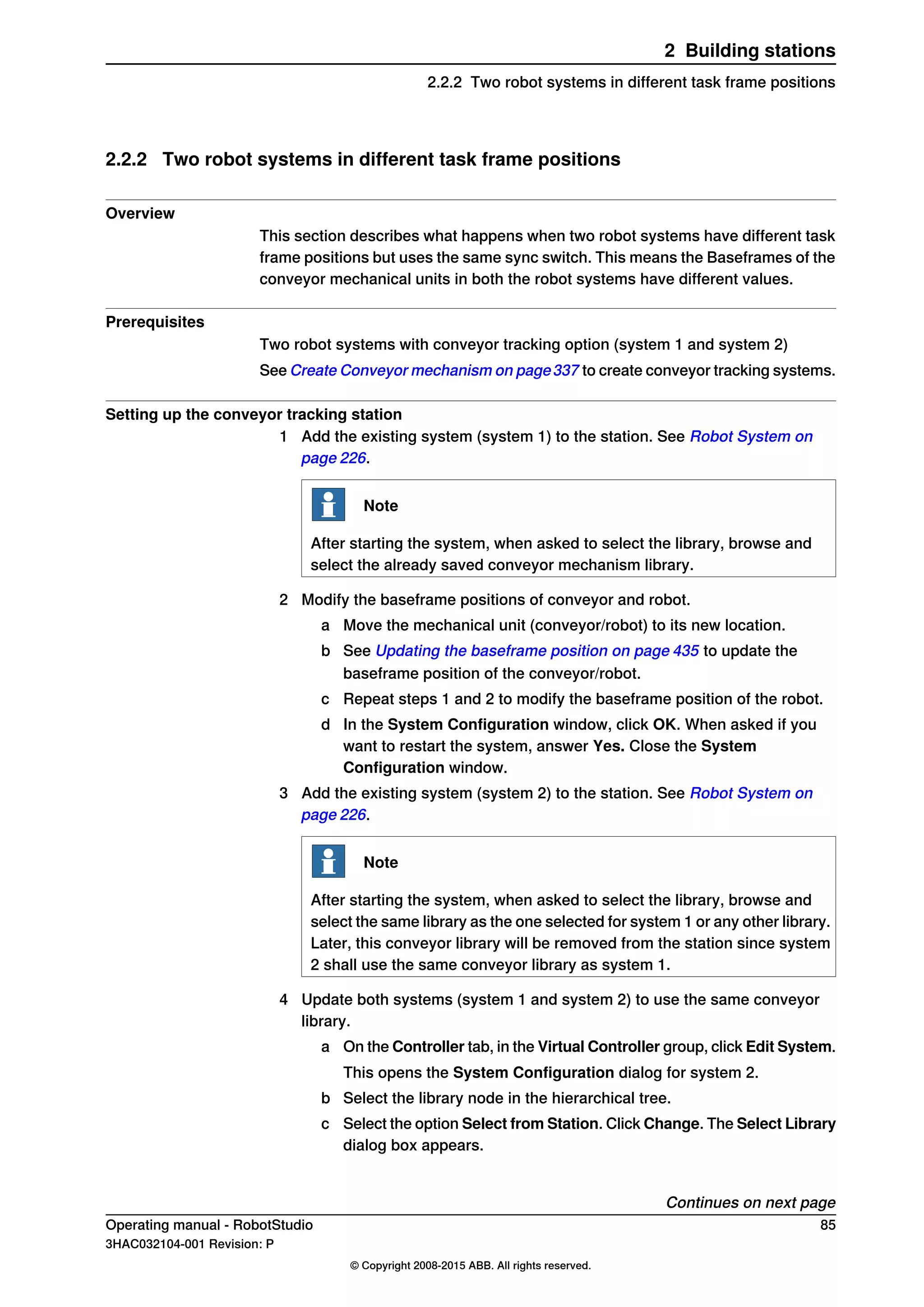
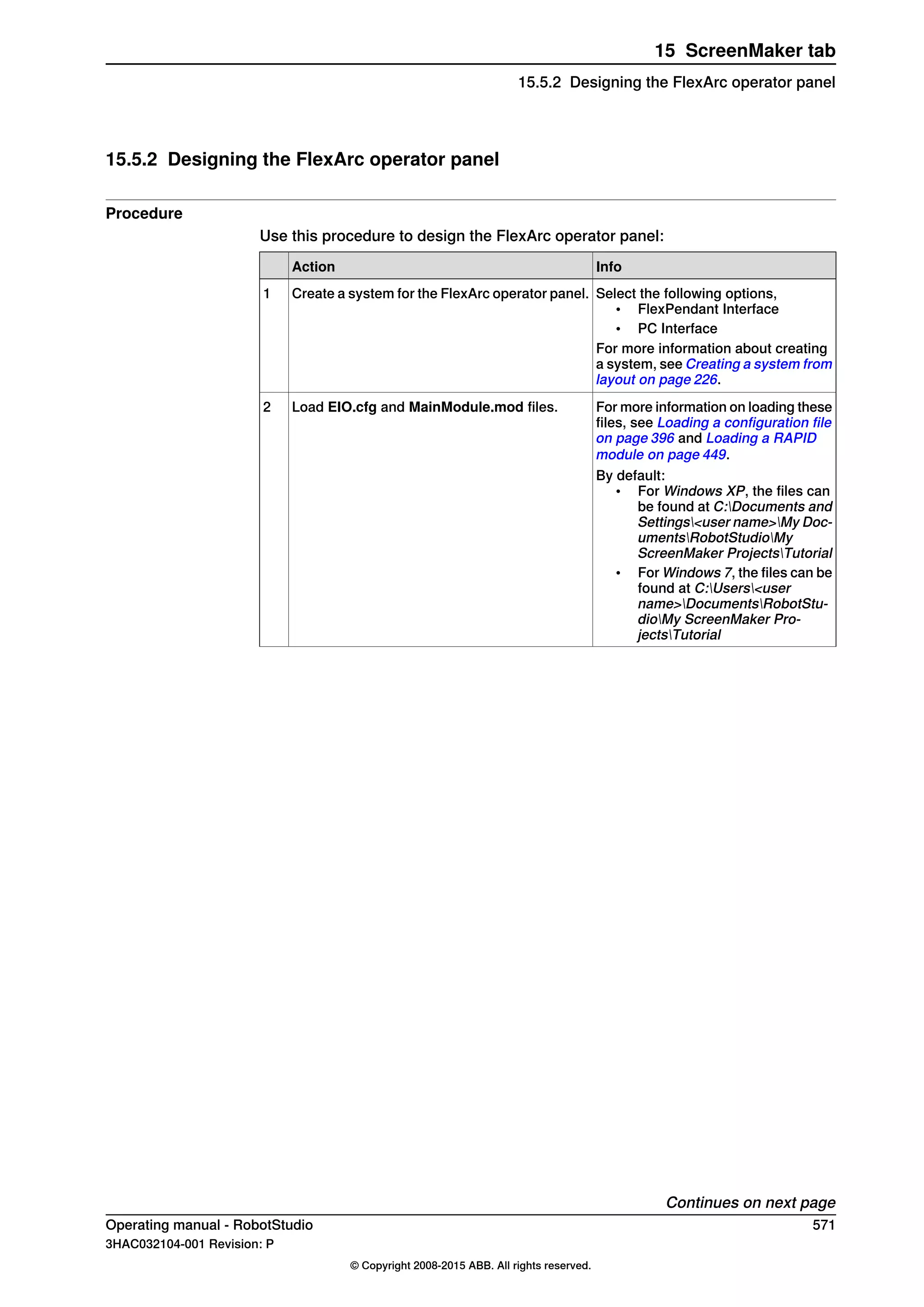
![How configurations are denoted
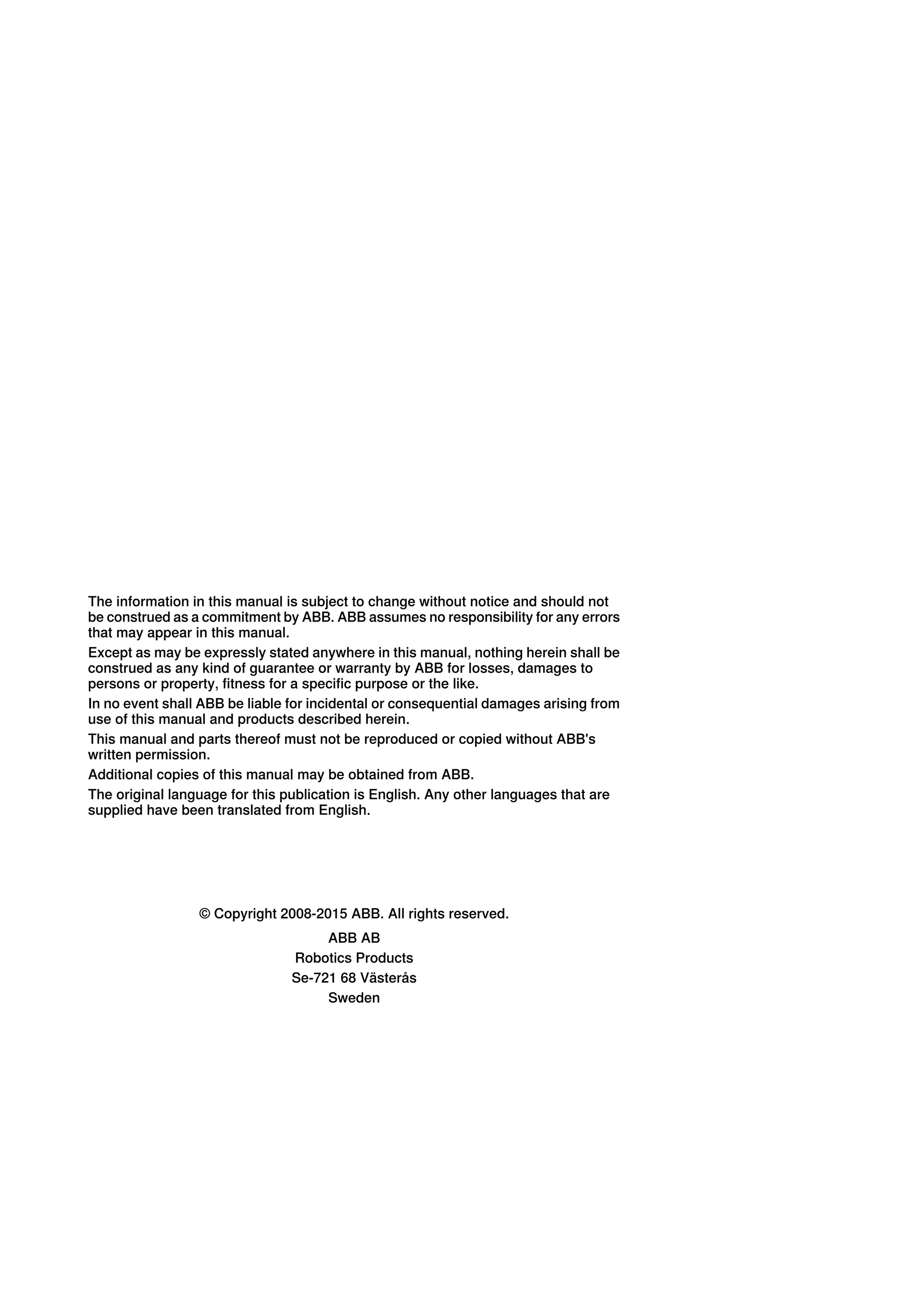
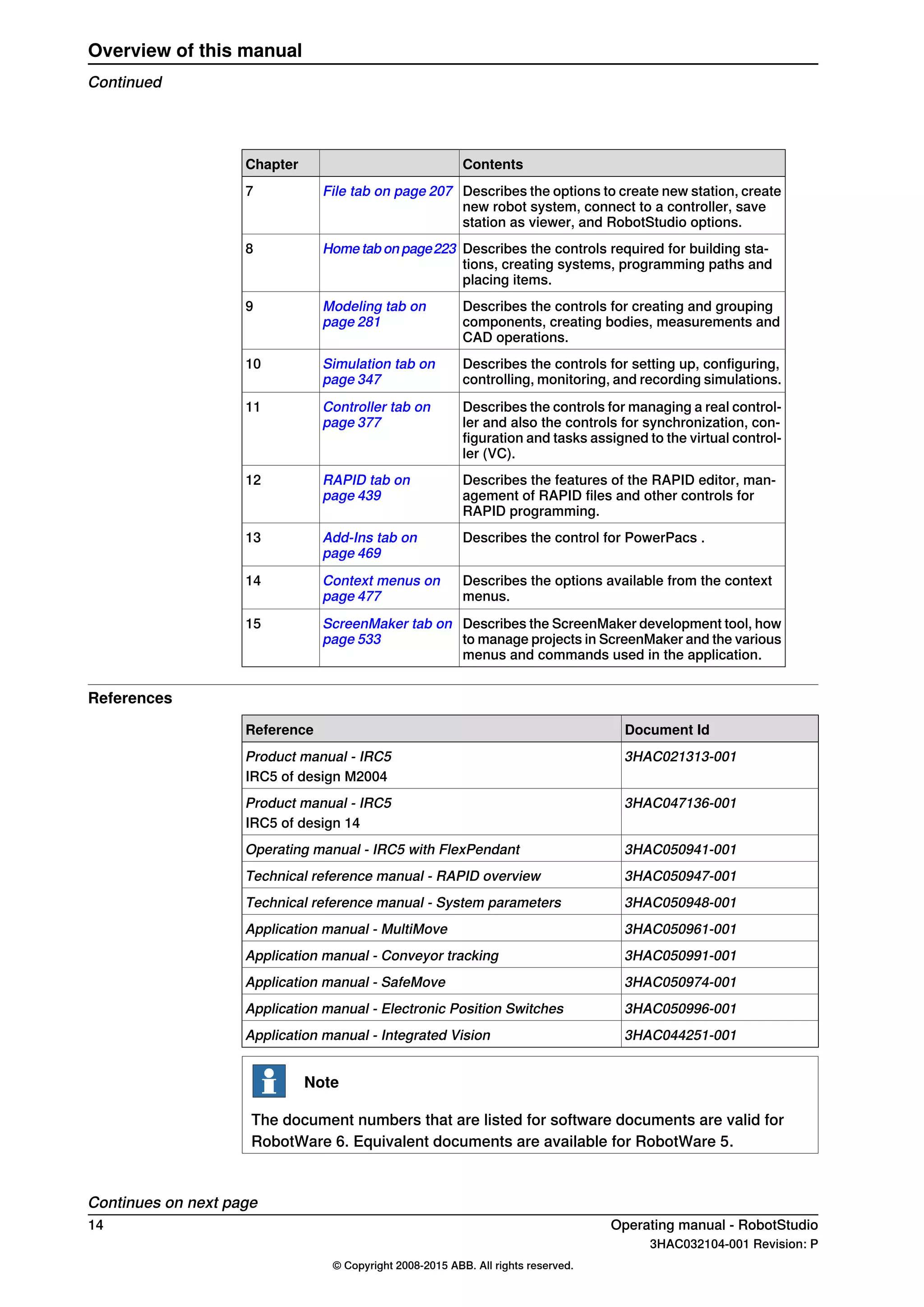
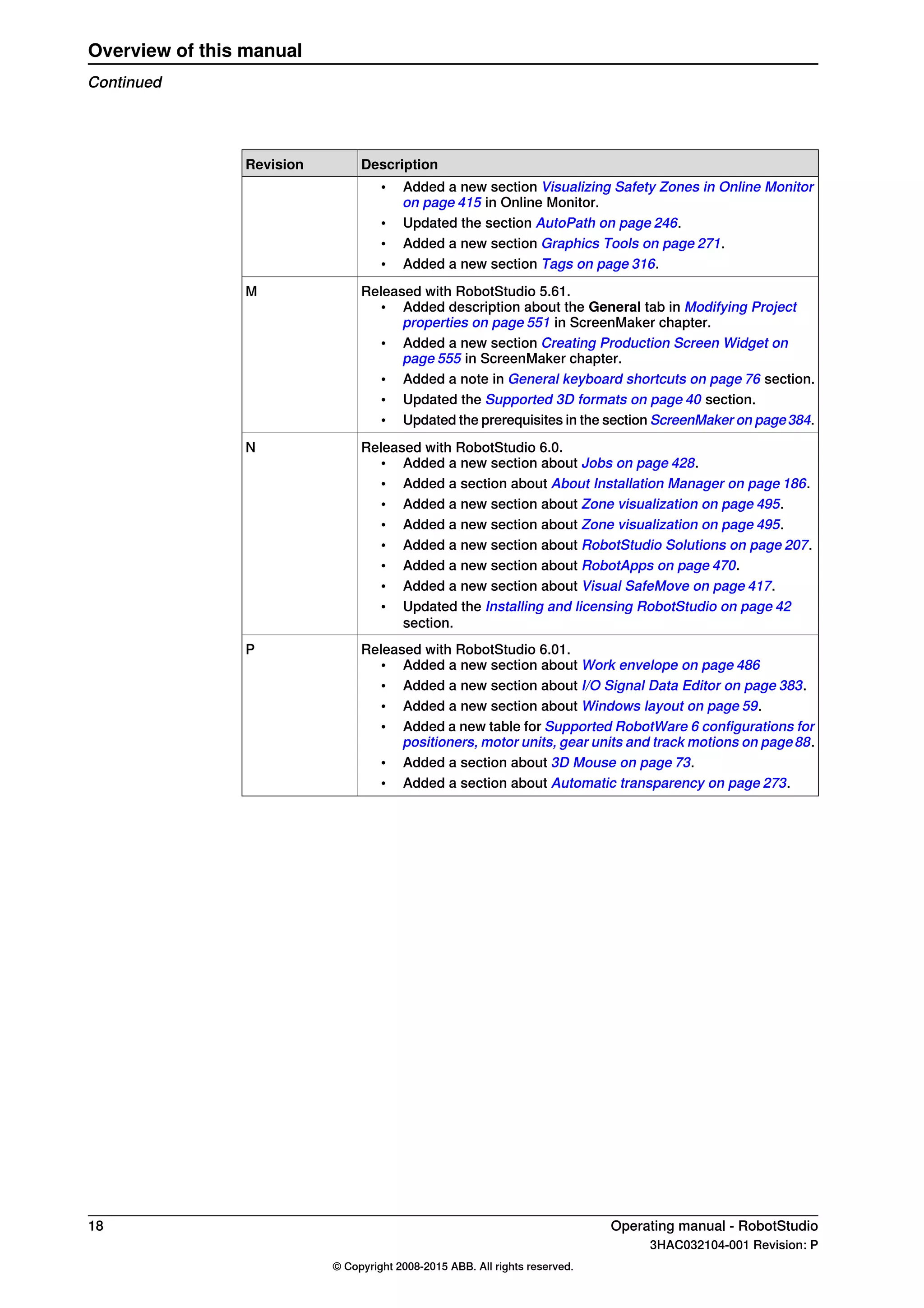
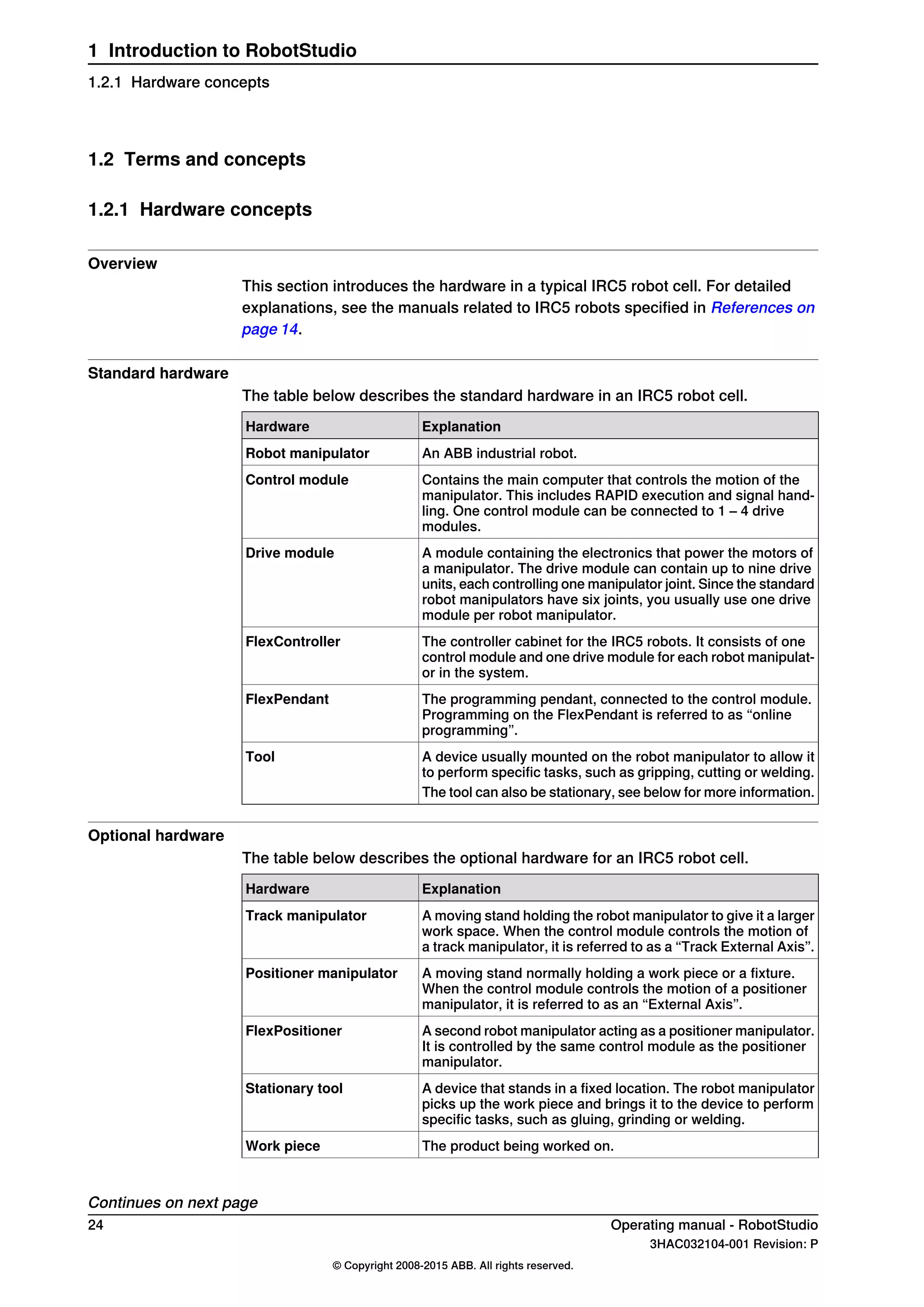
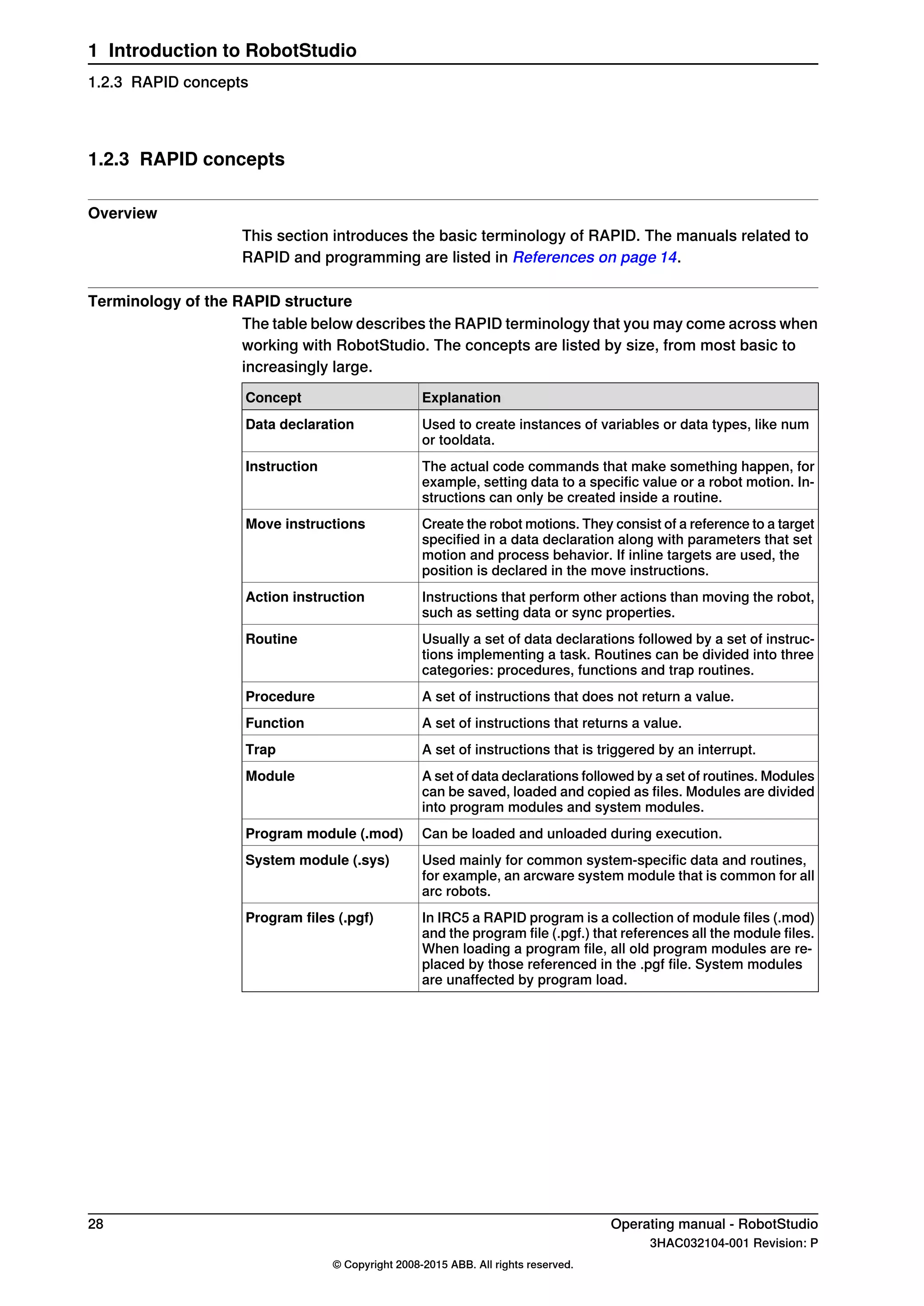
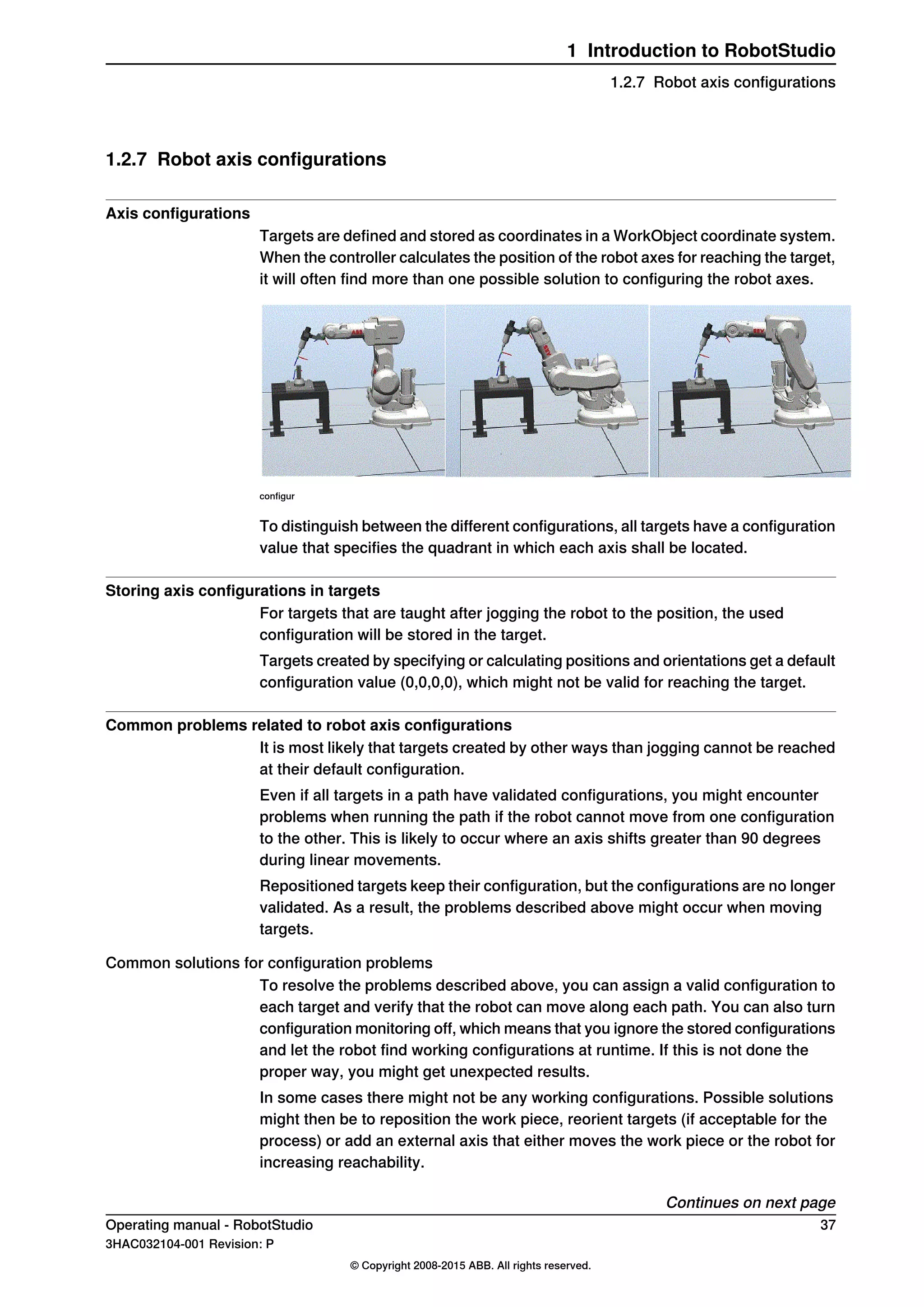
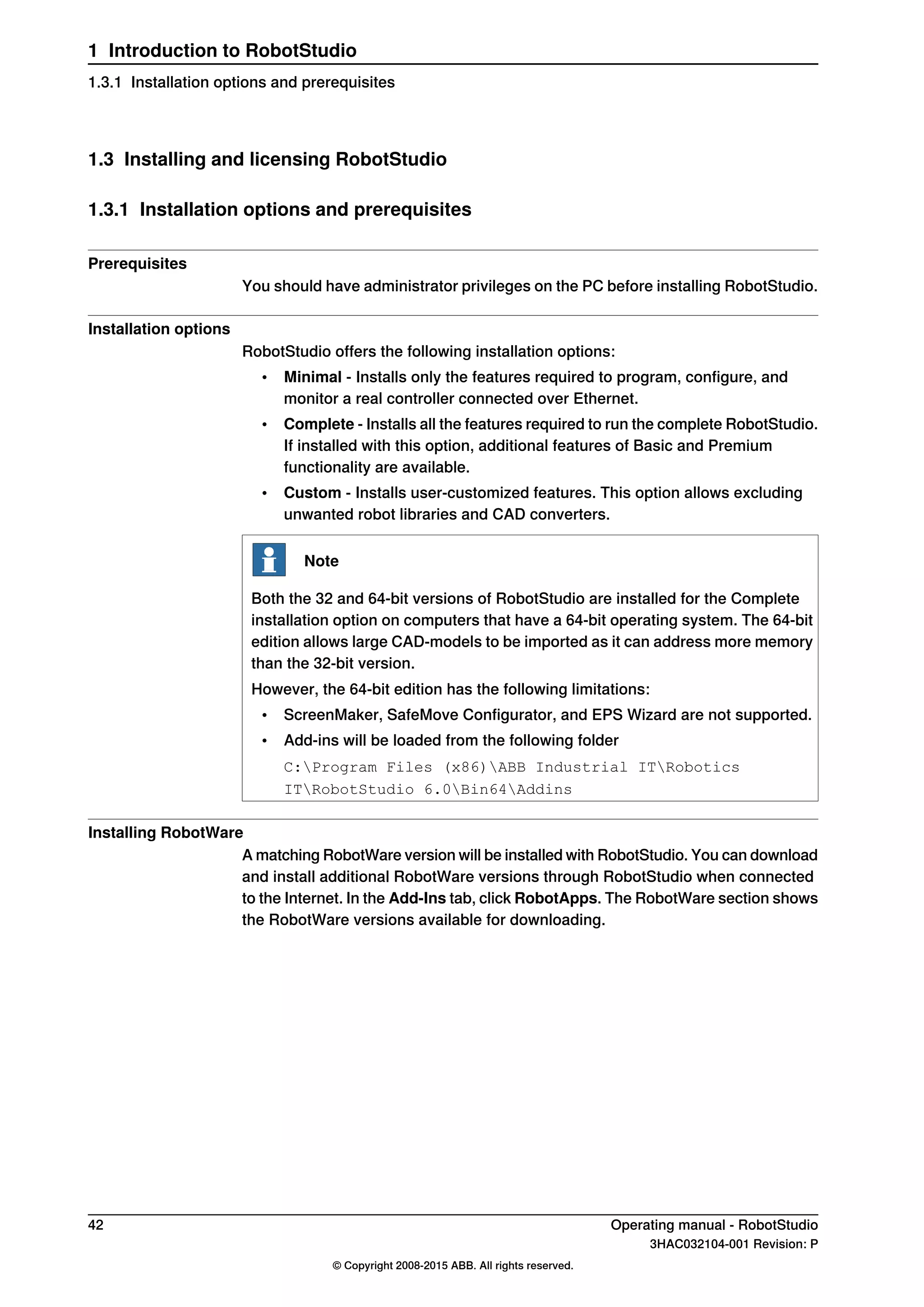
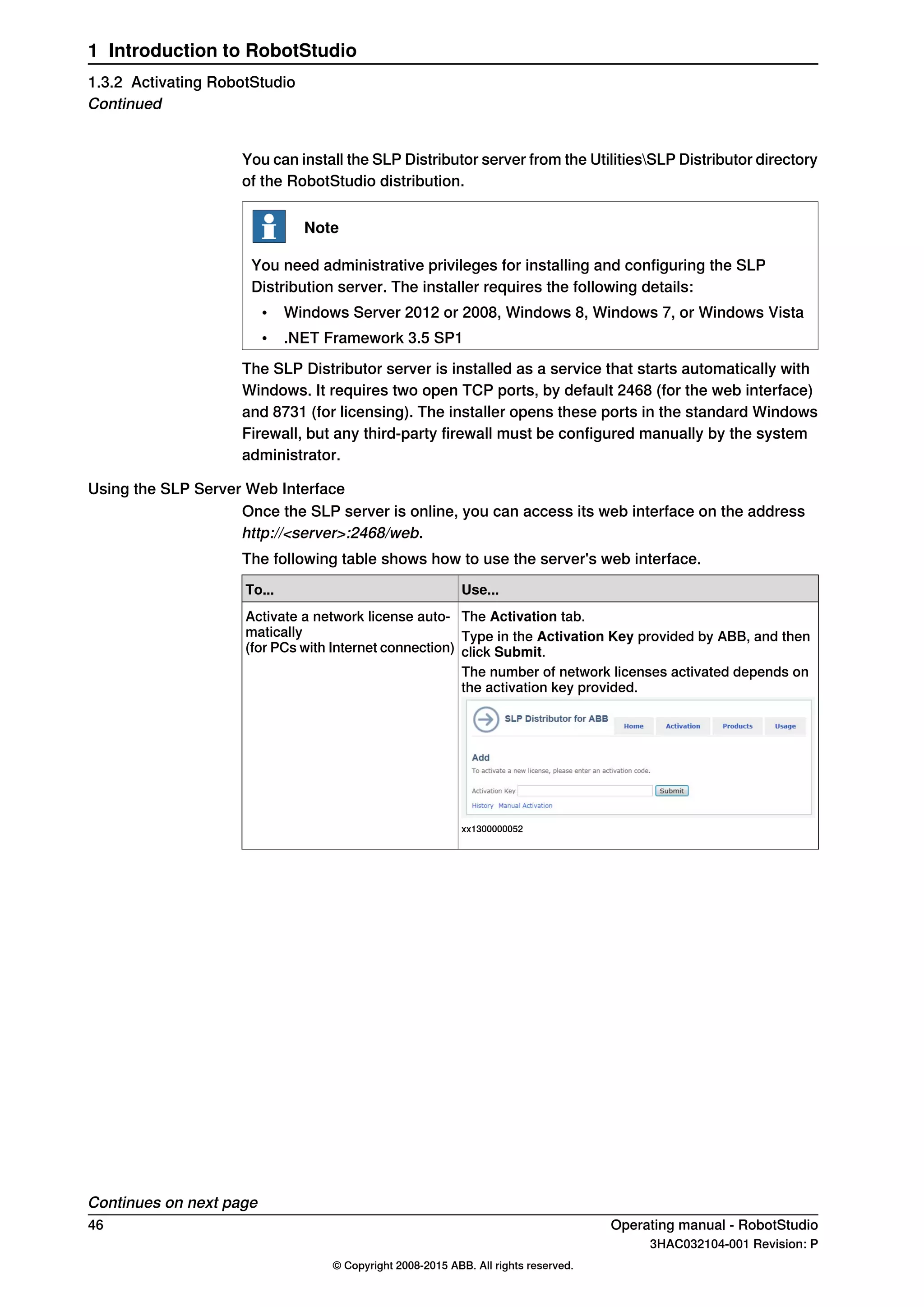
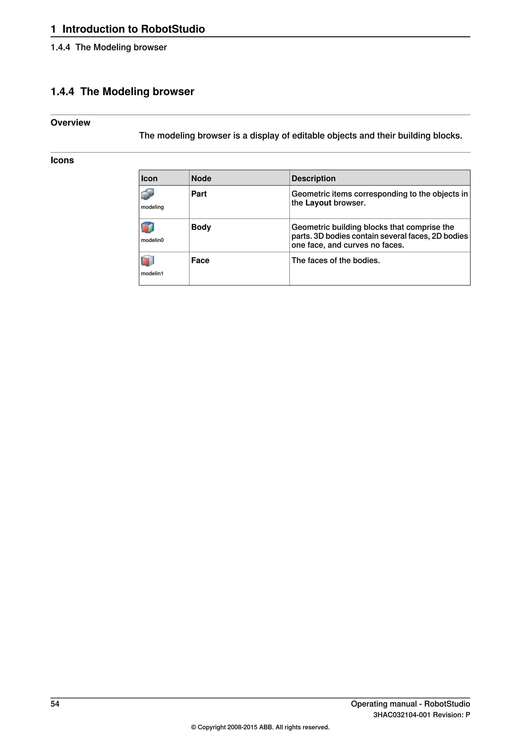
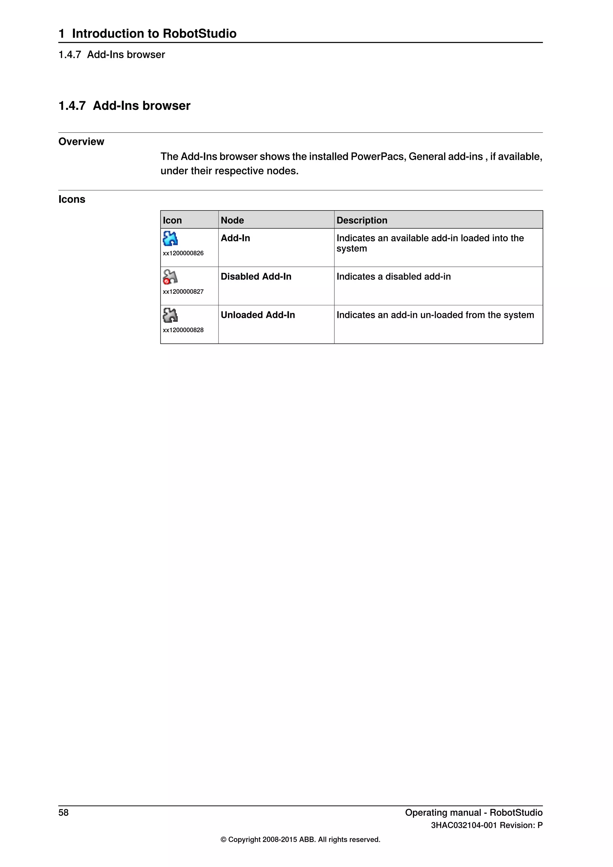
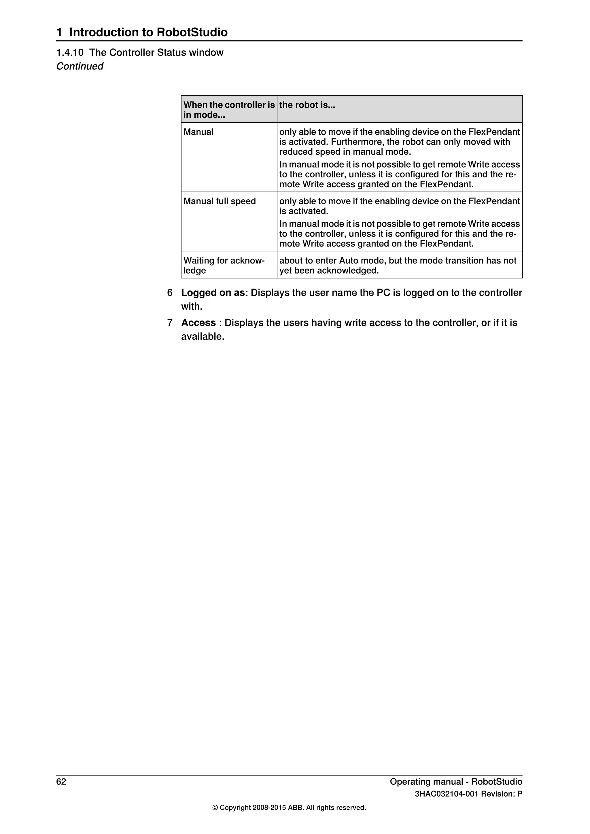
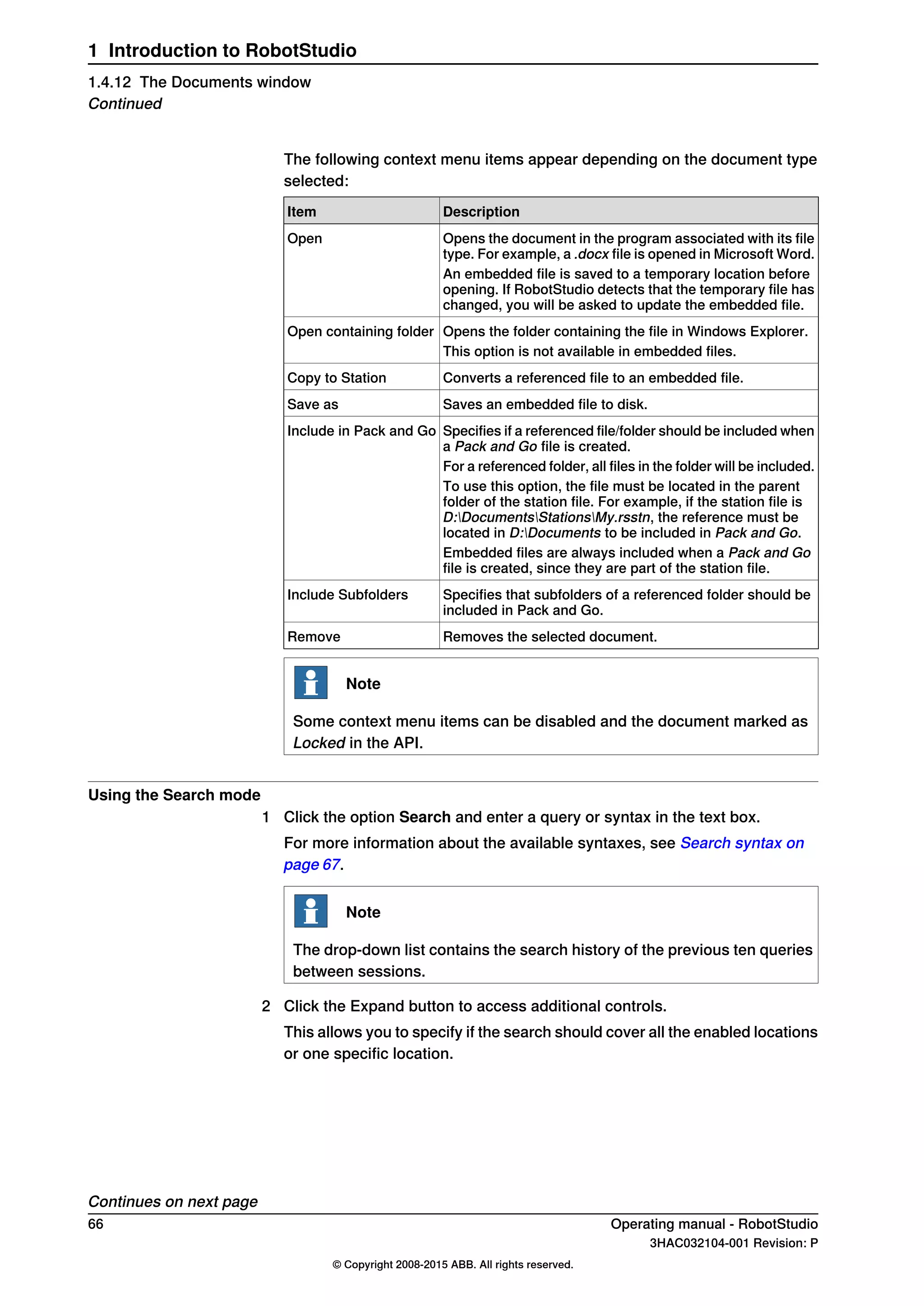
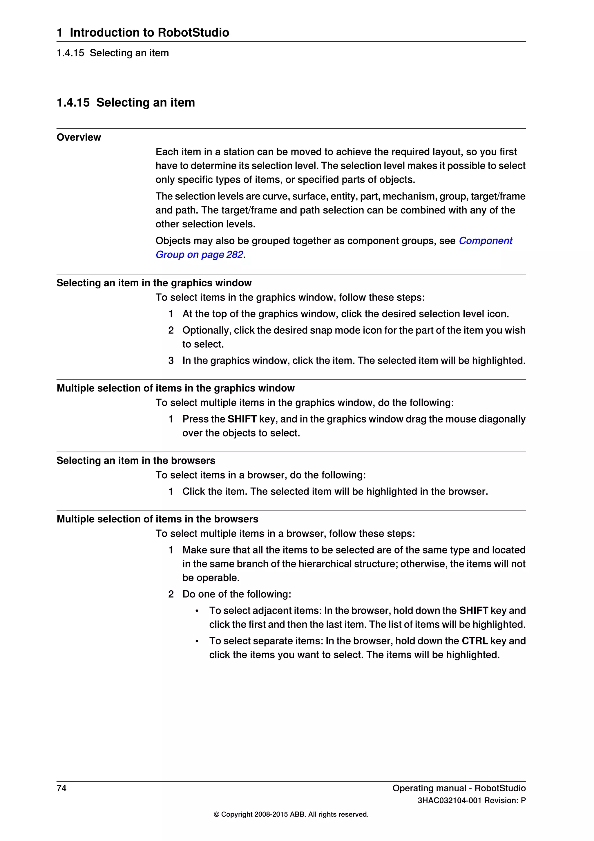
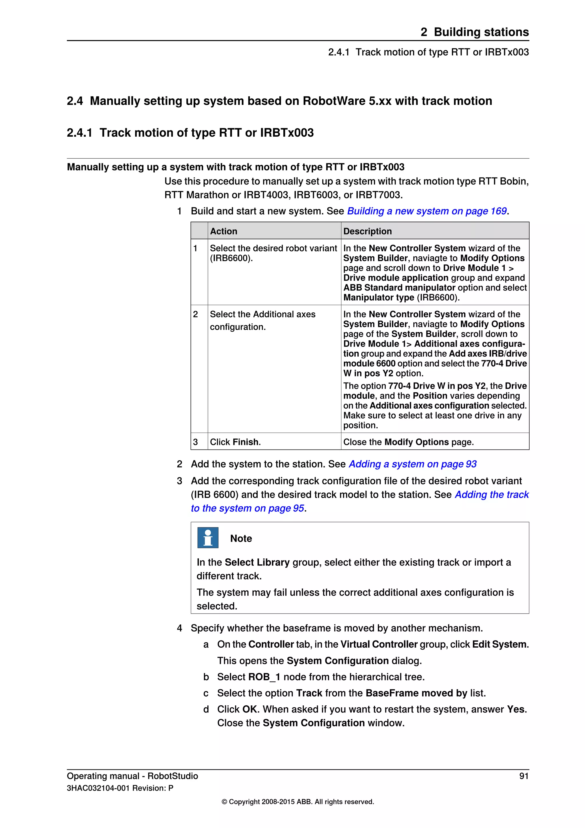
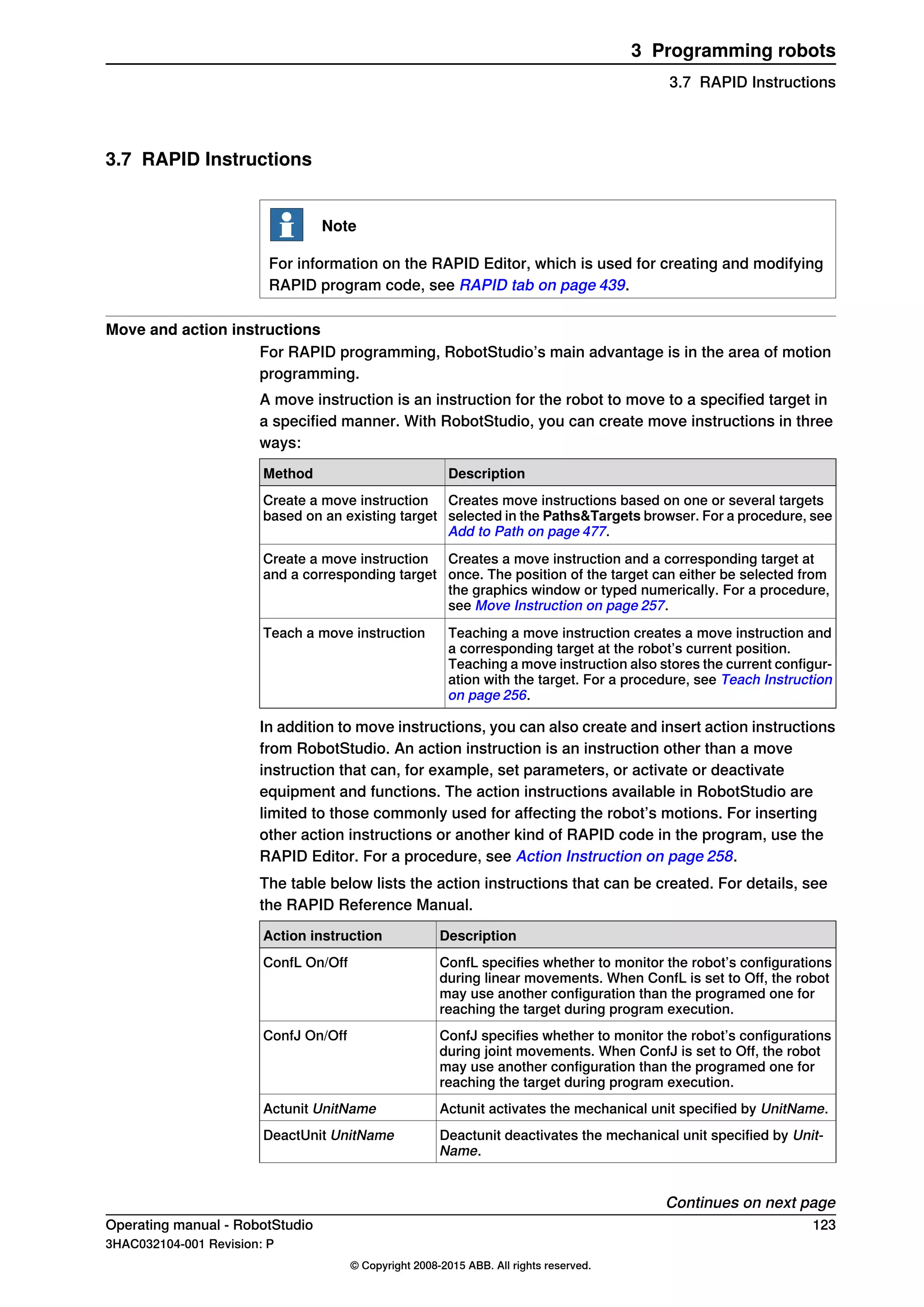
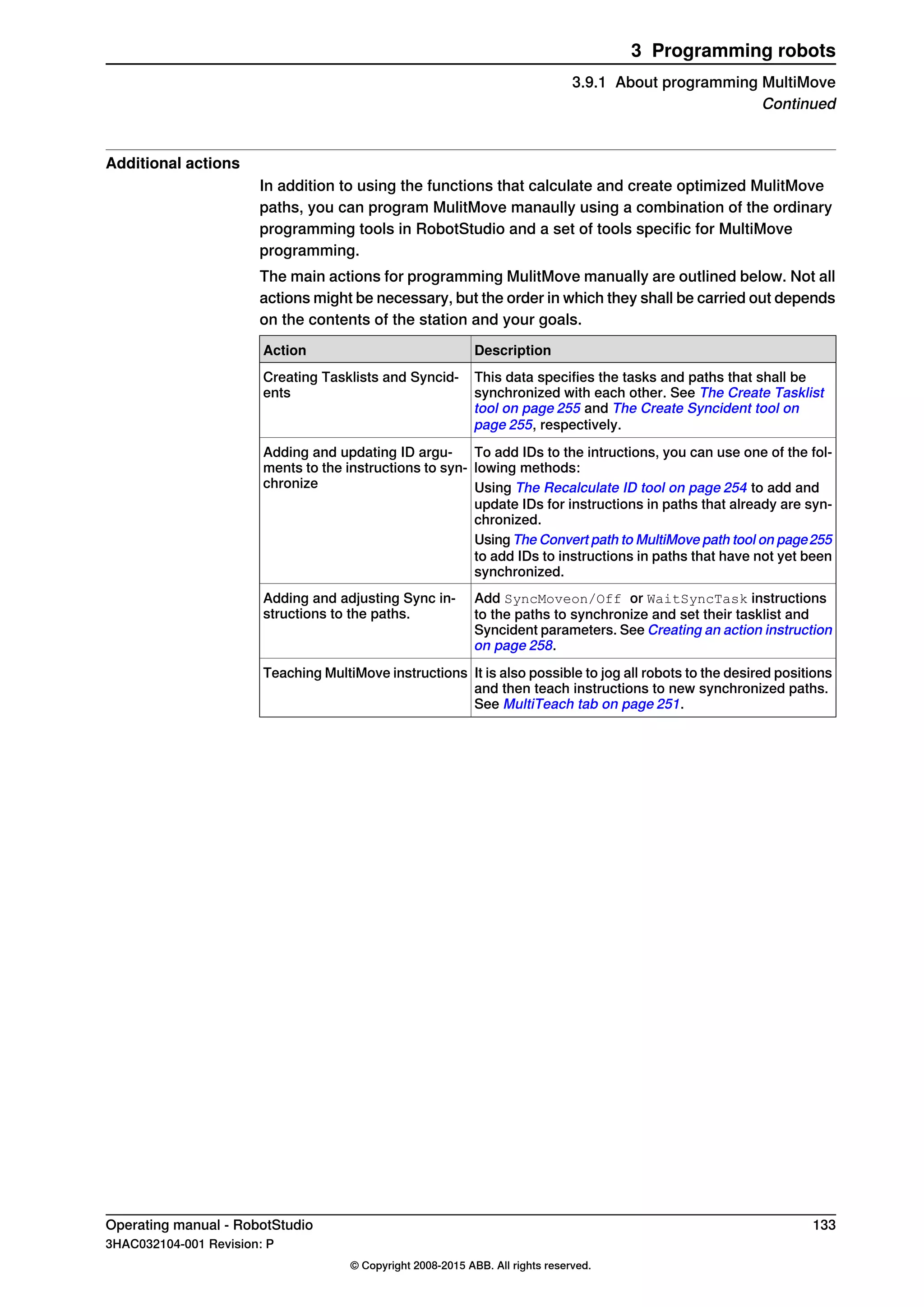
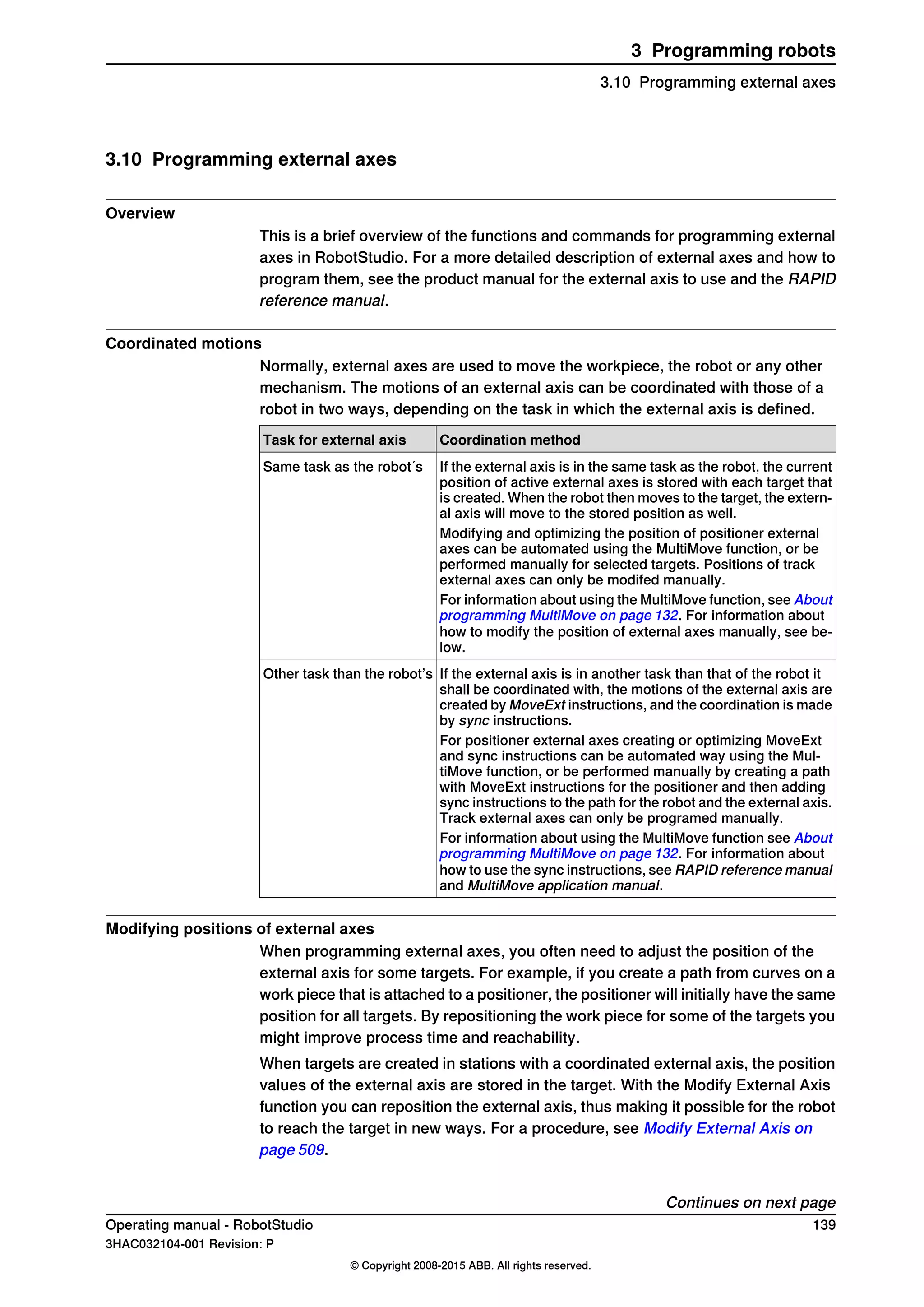
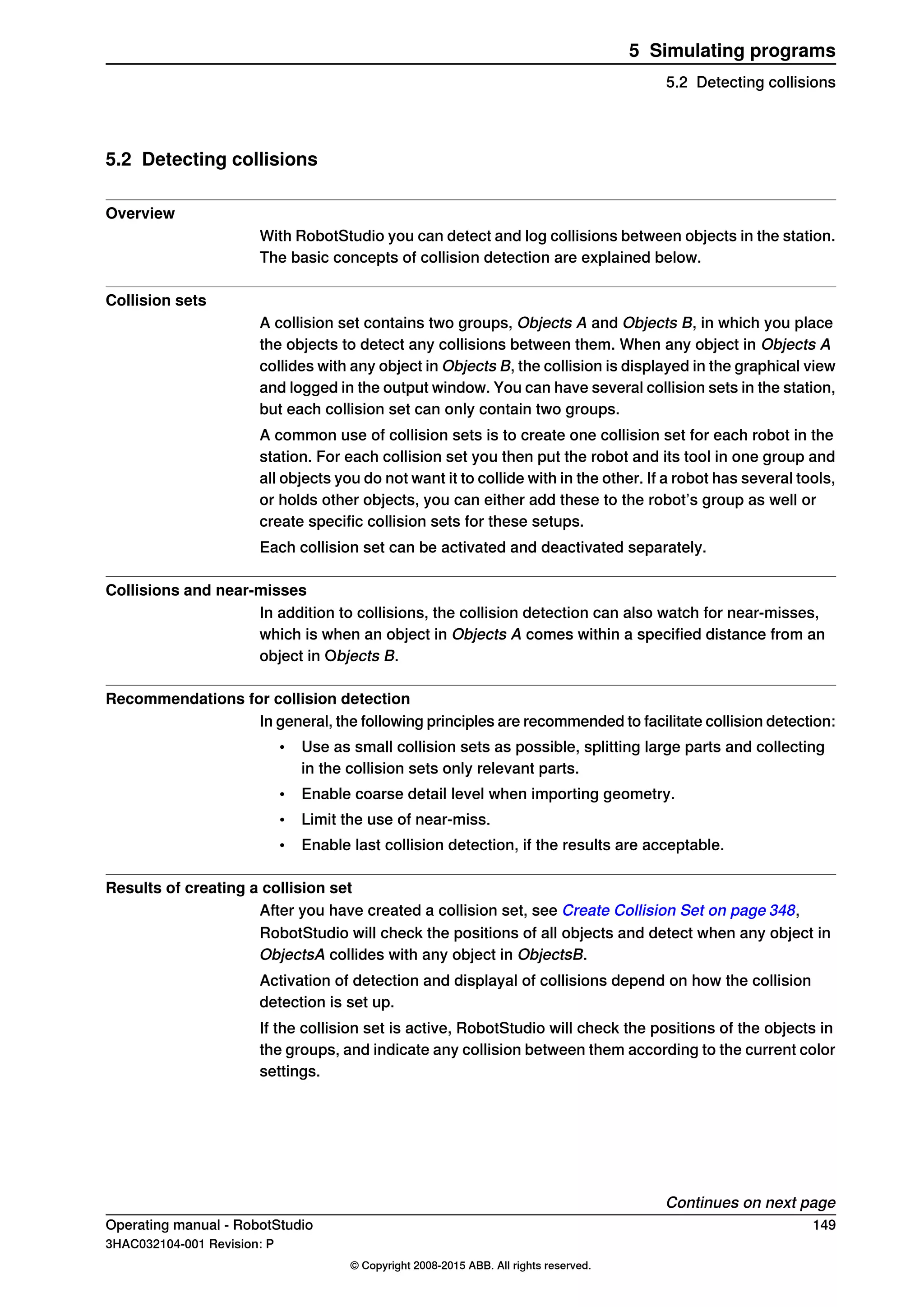
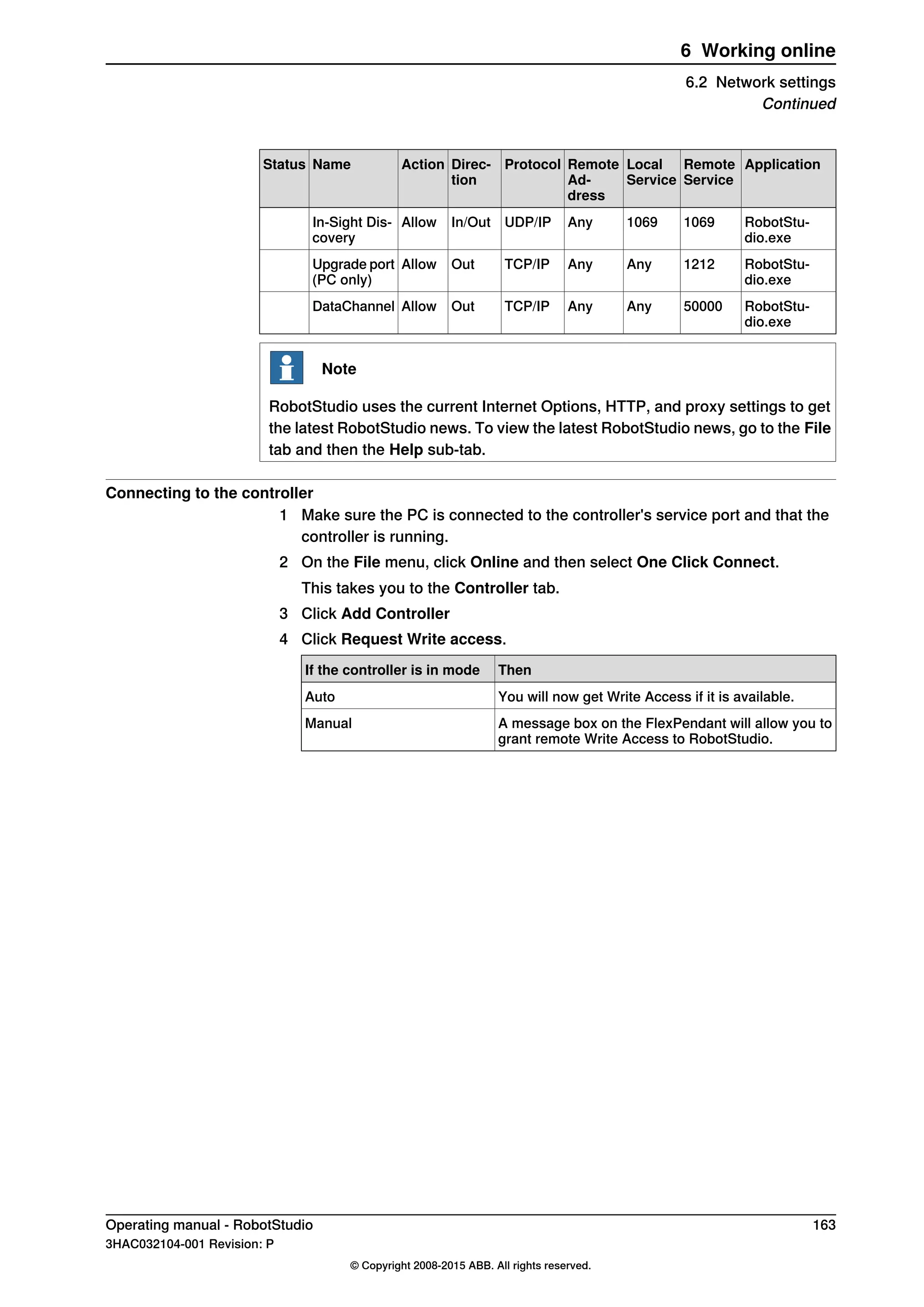
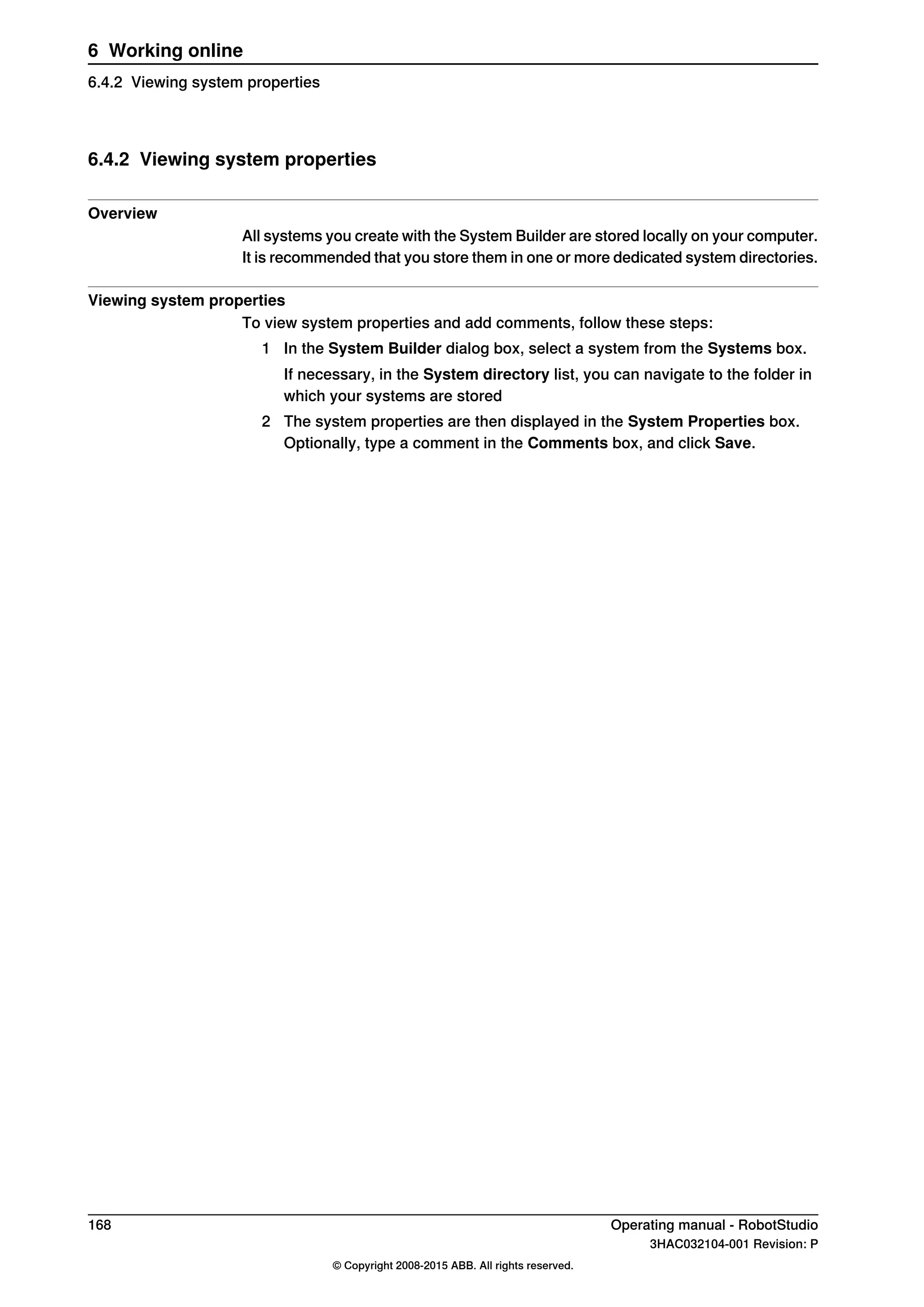
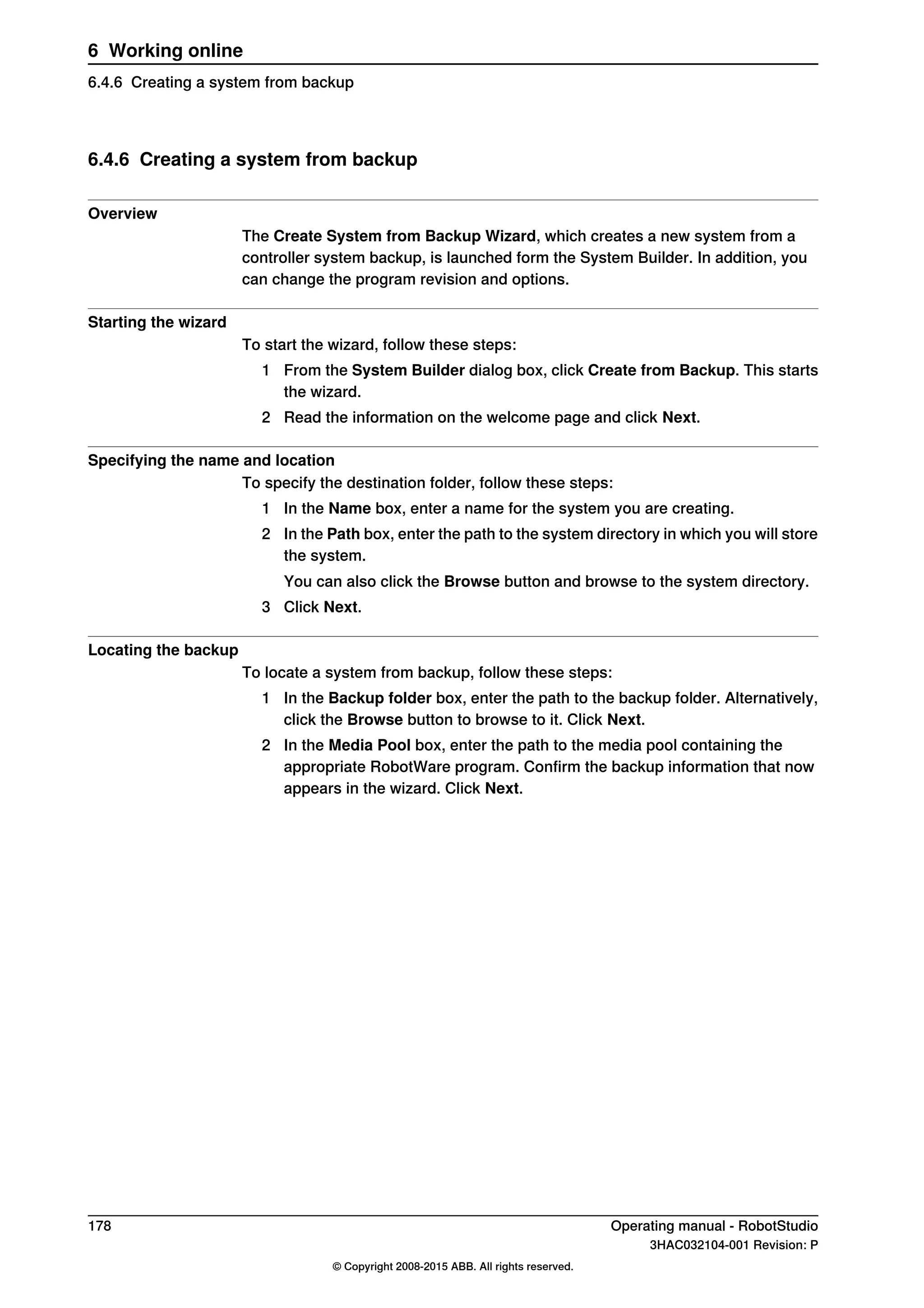
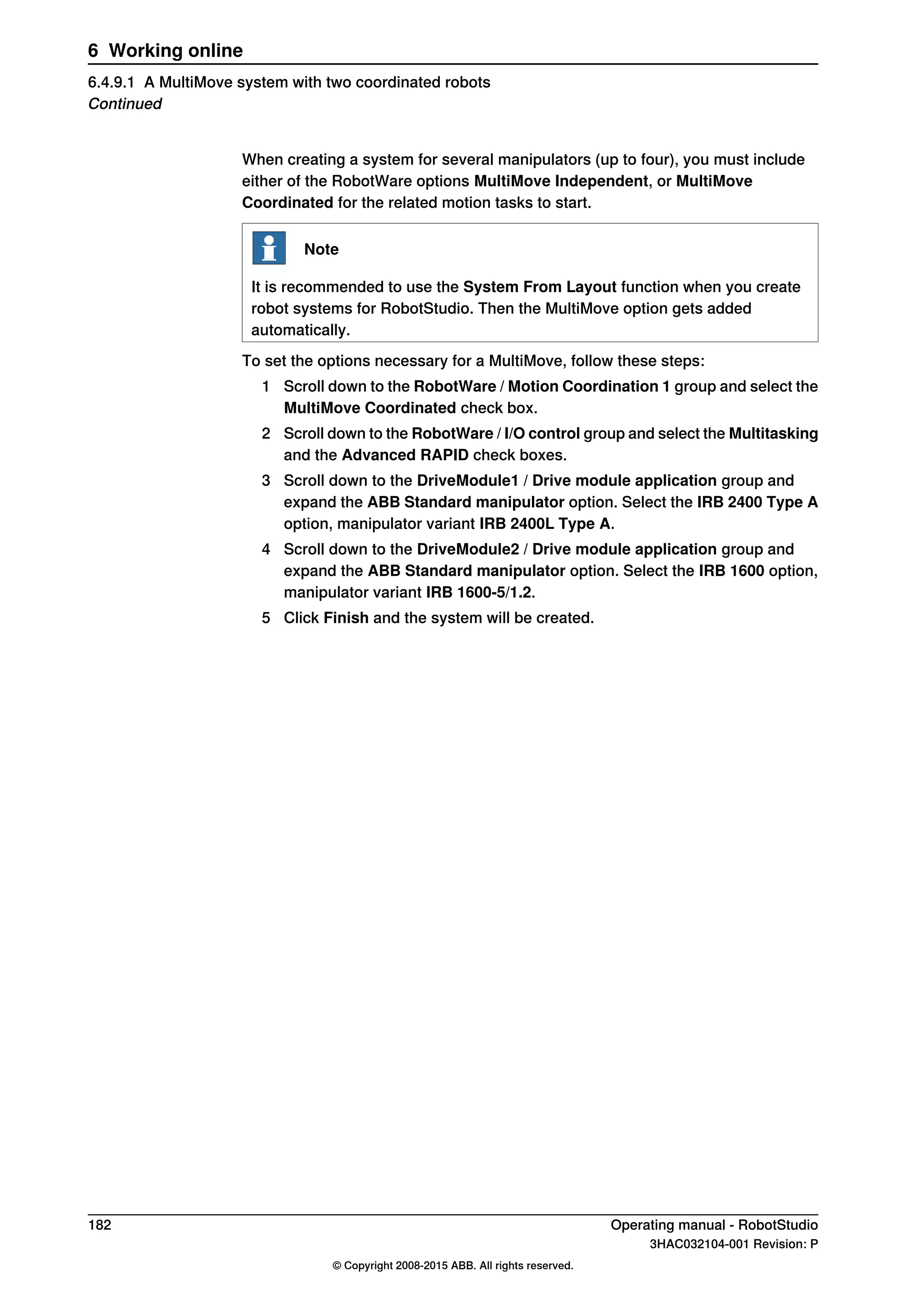
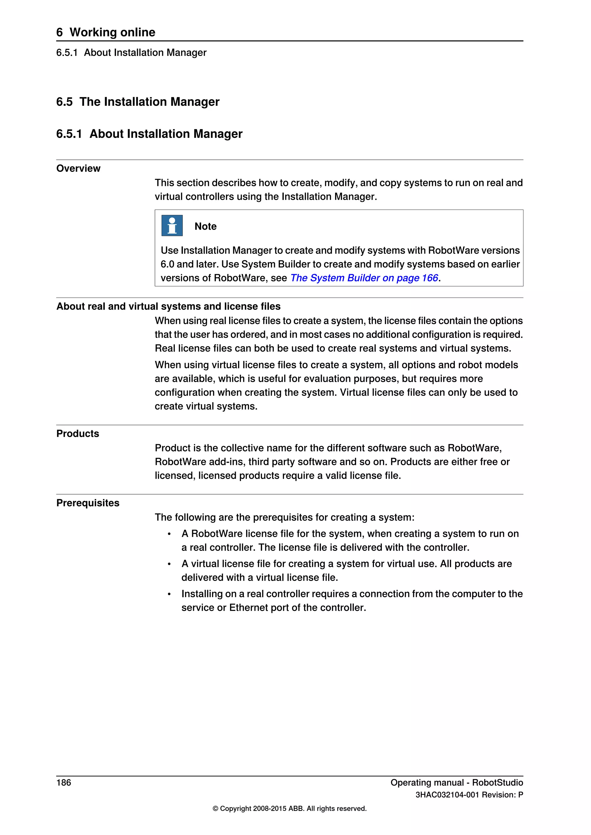
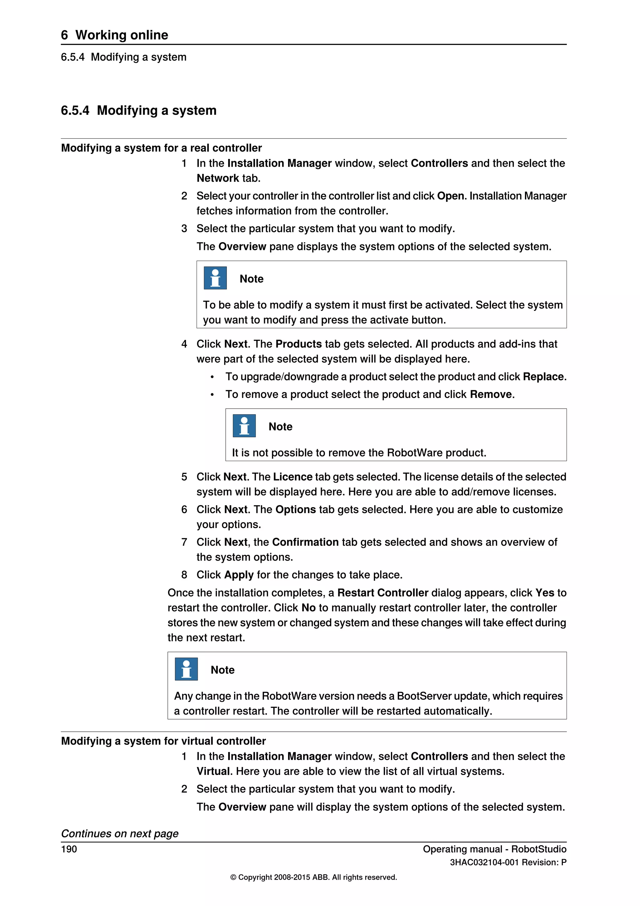
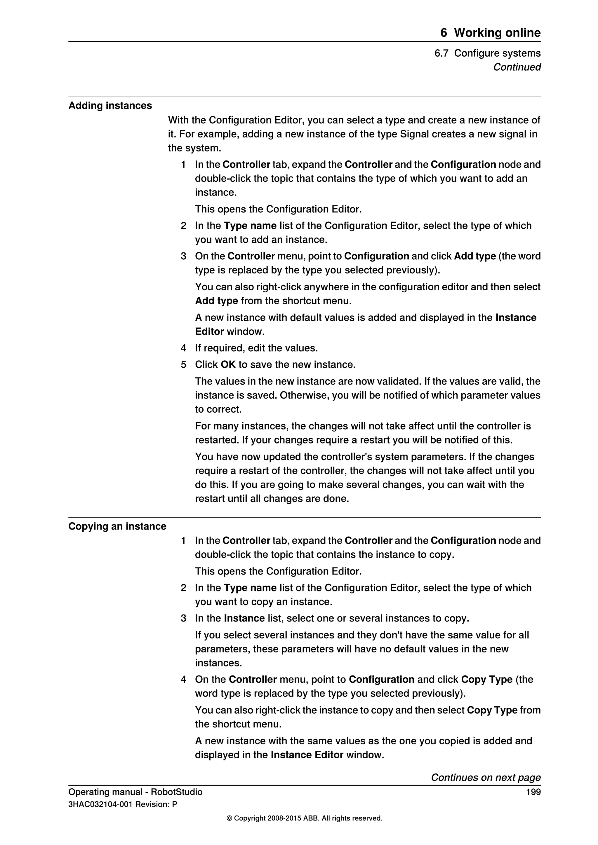
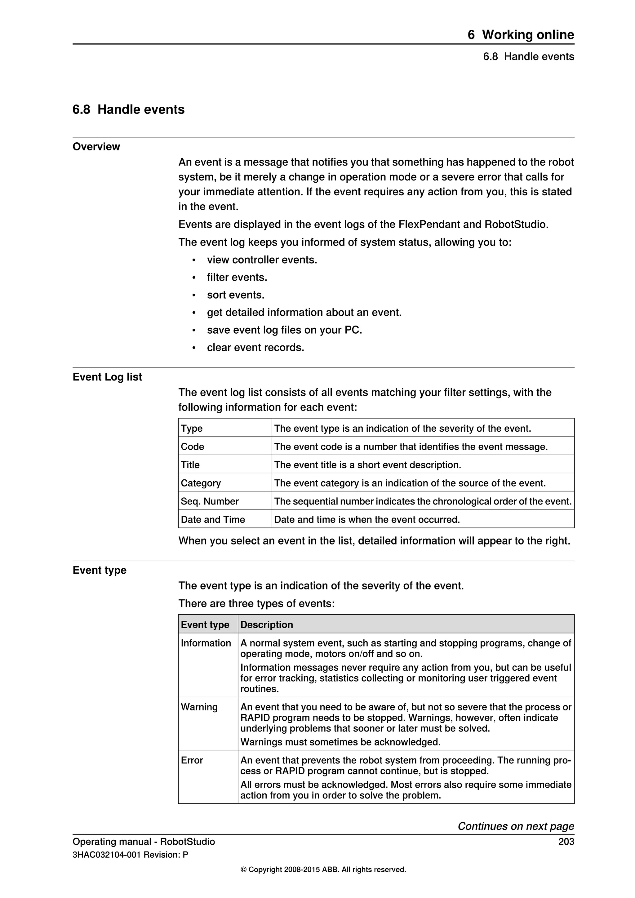
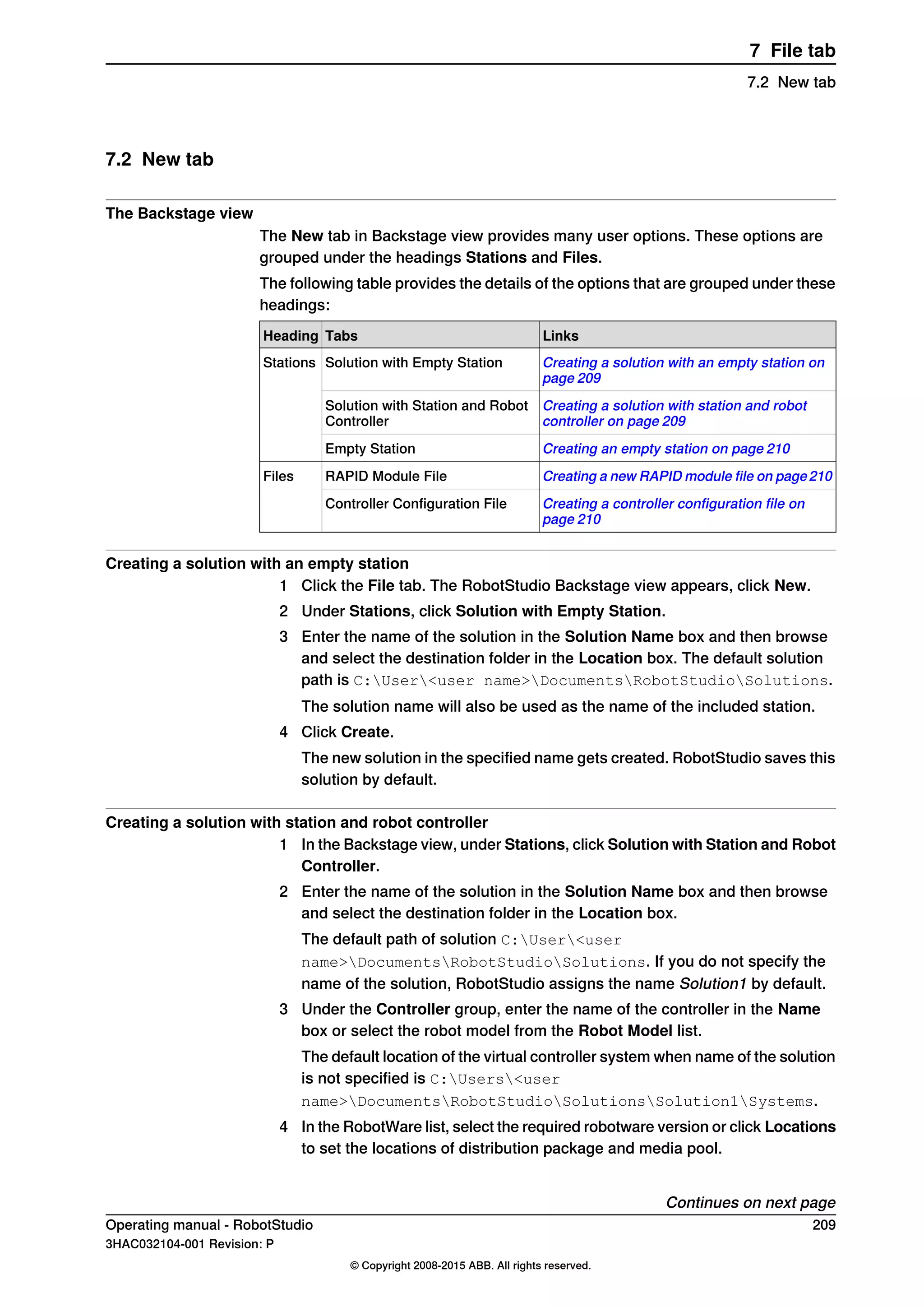
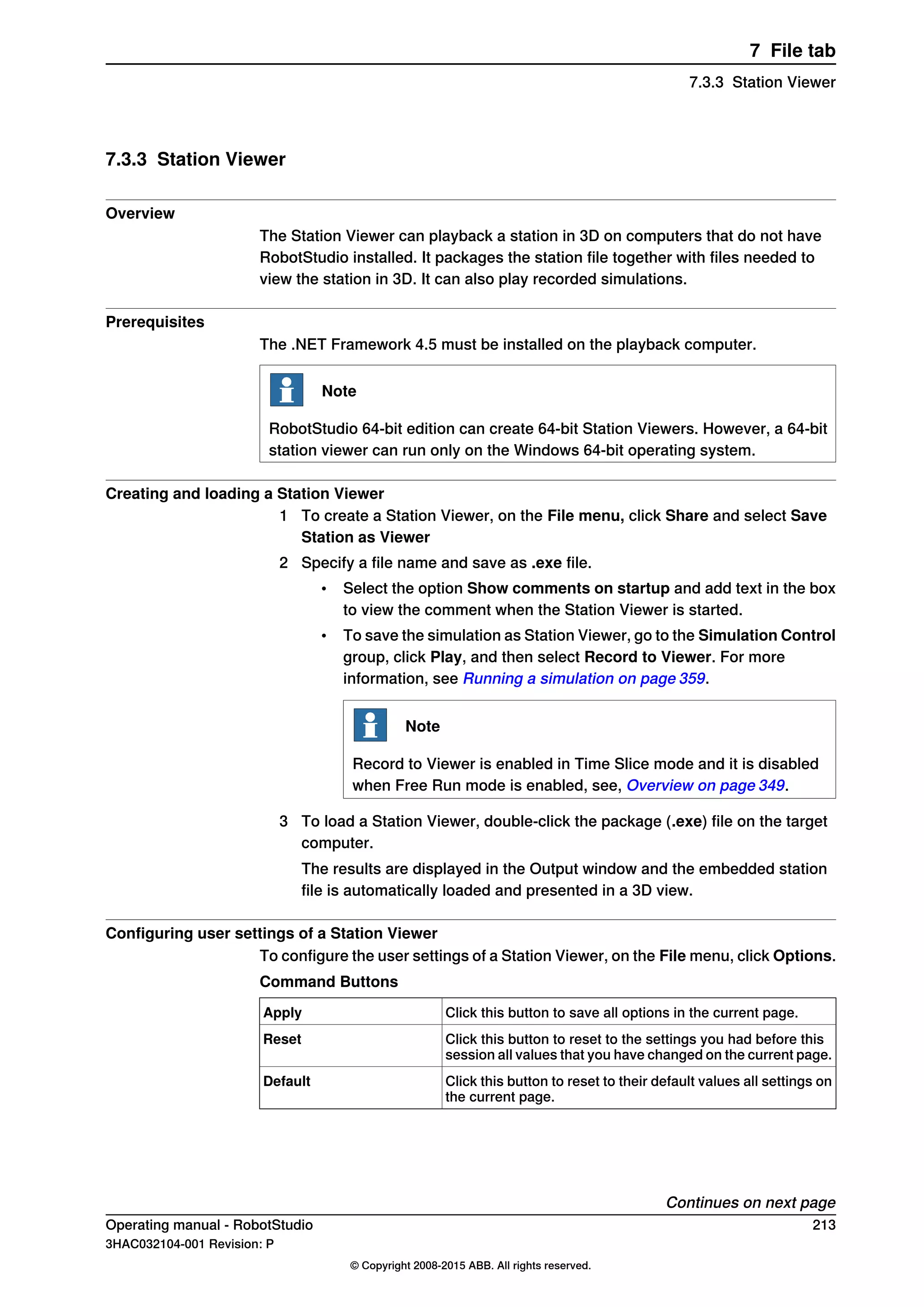
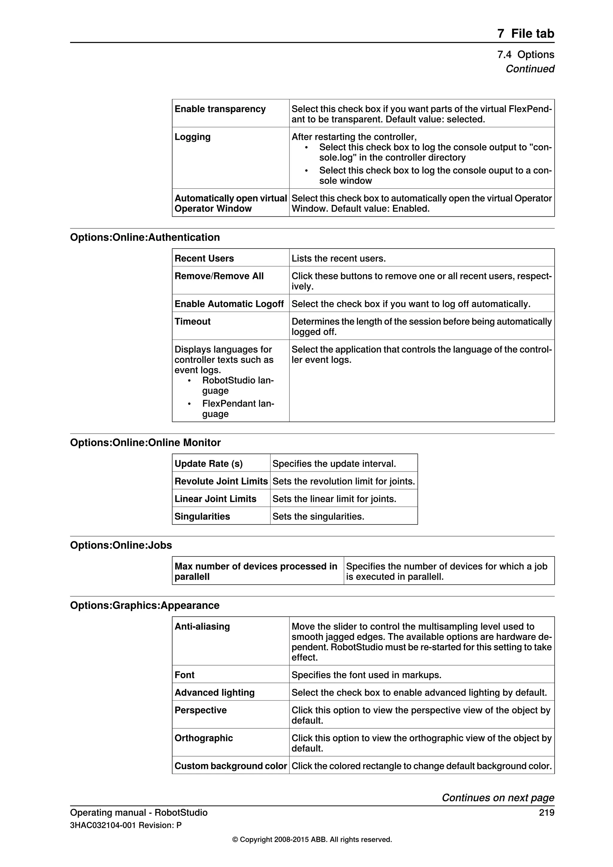
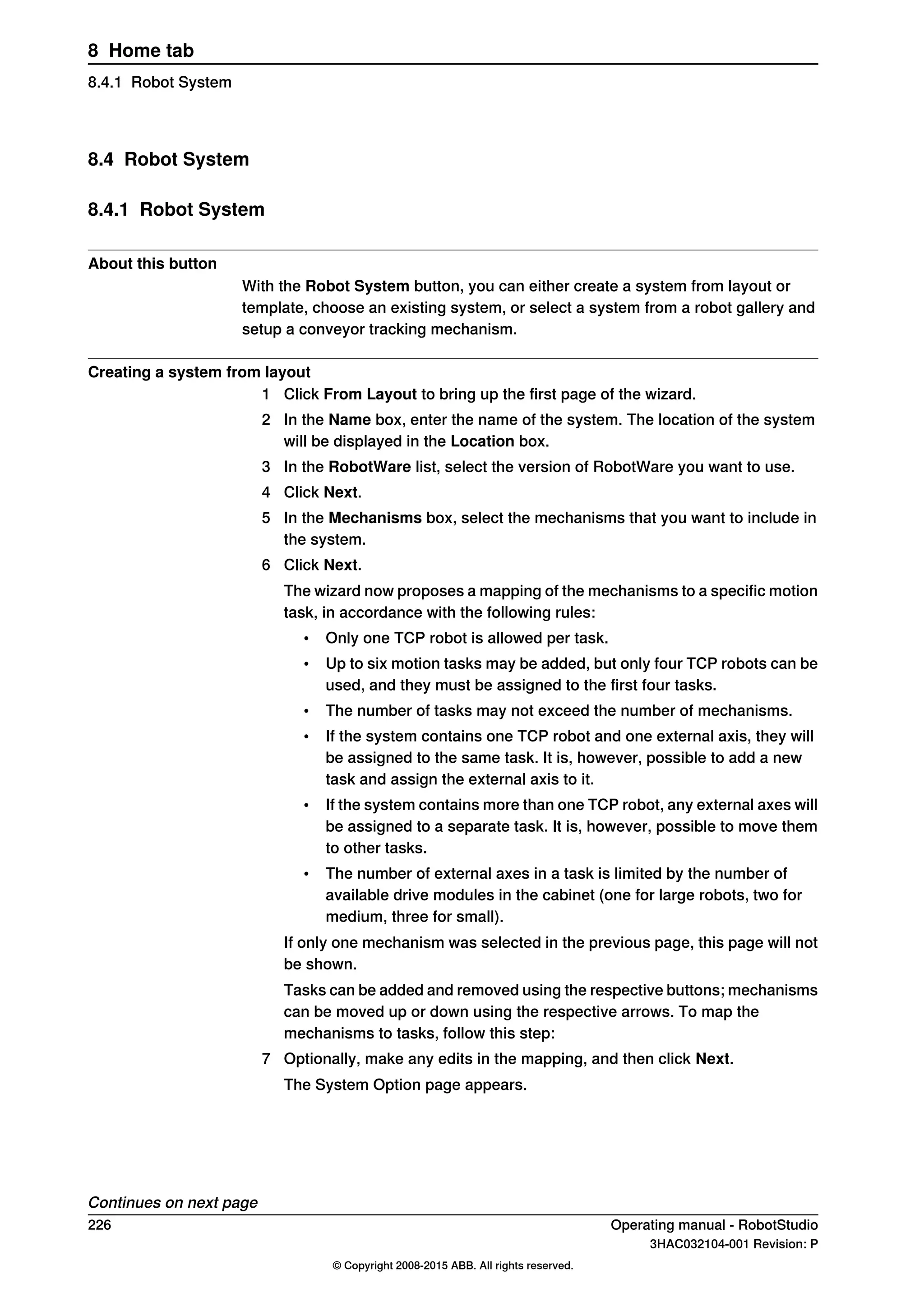
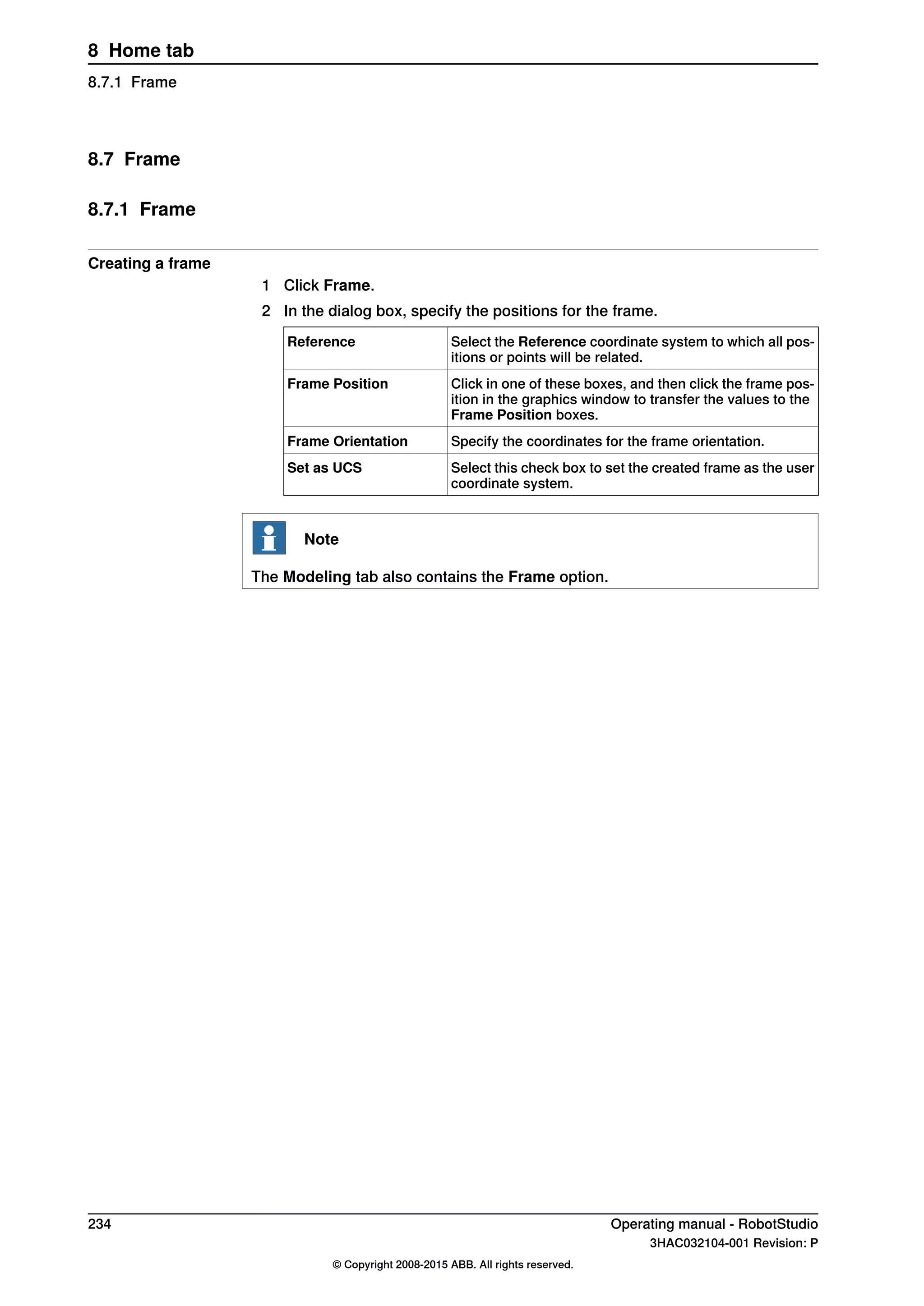
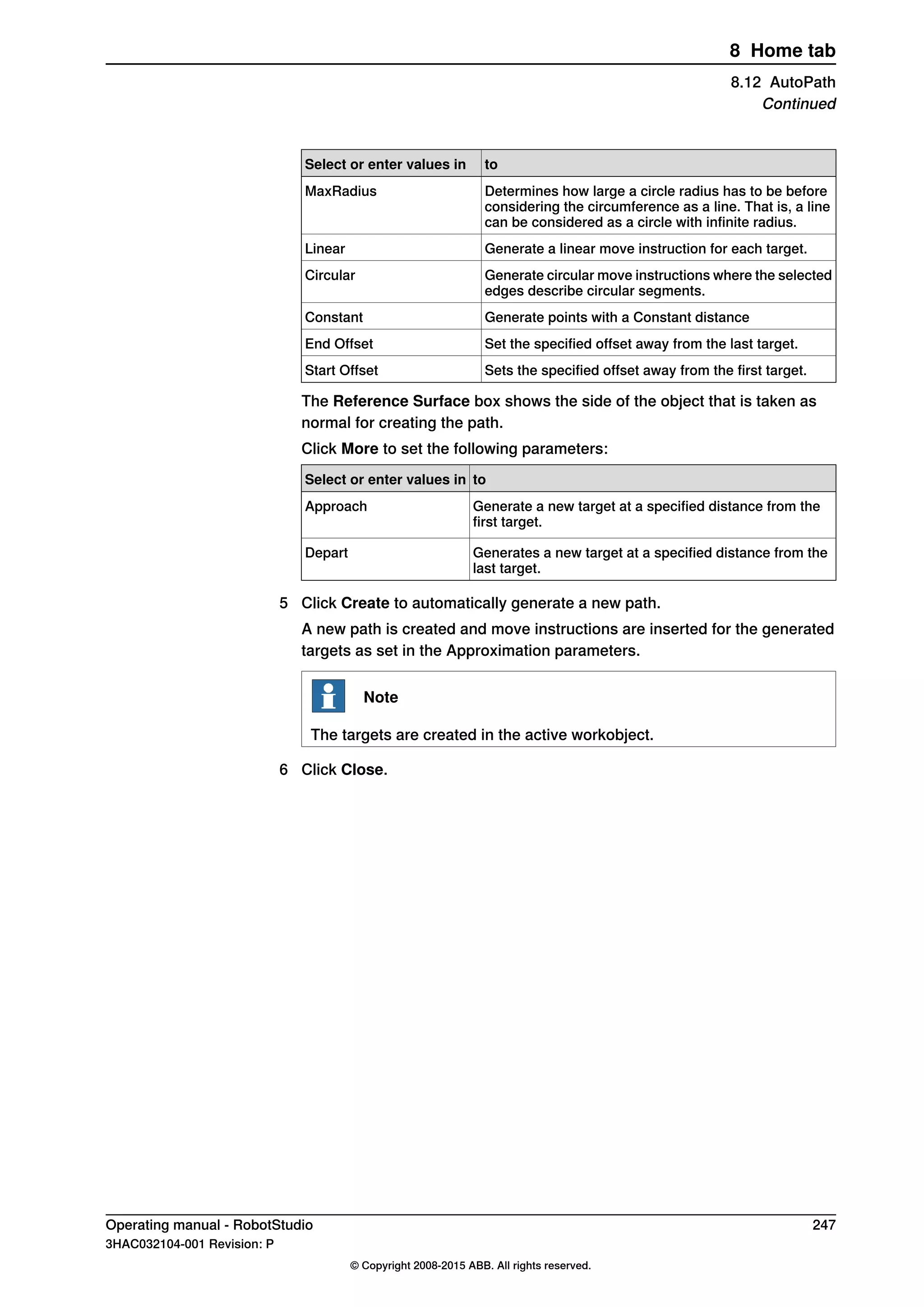
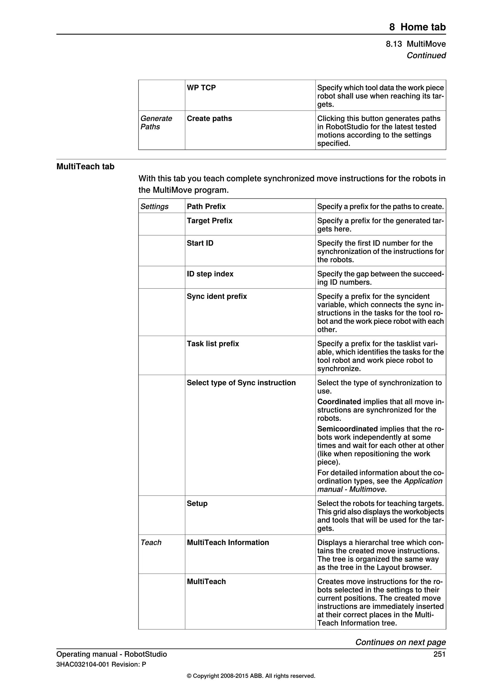
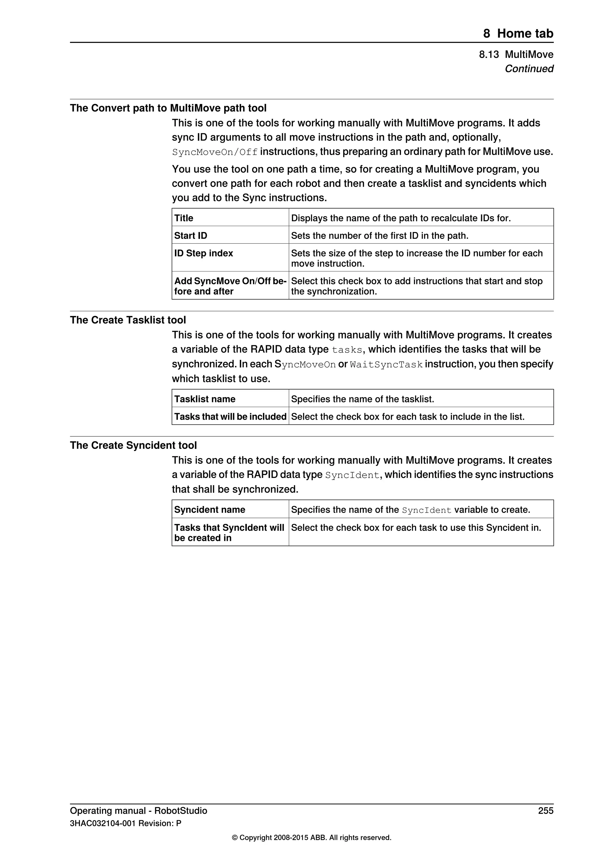
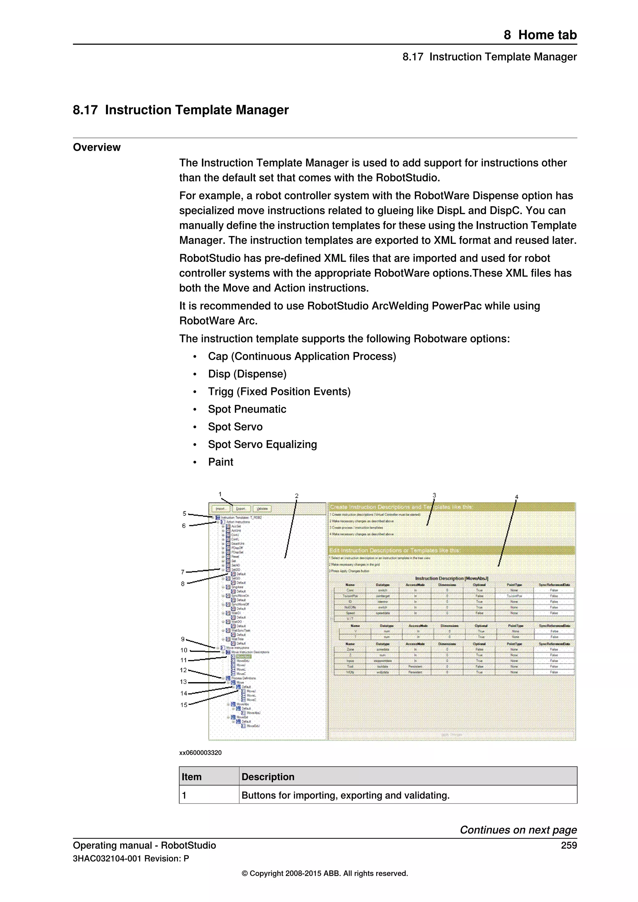
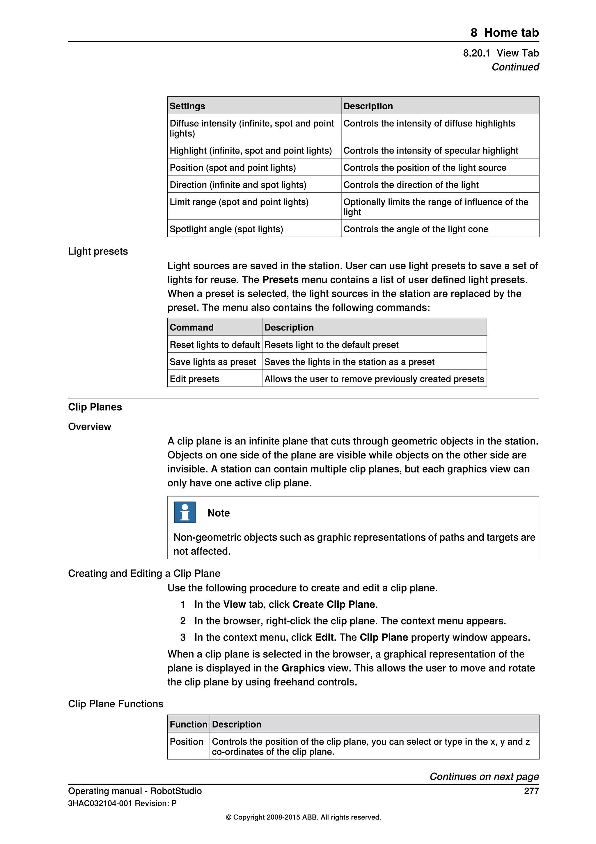
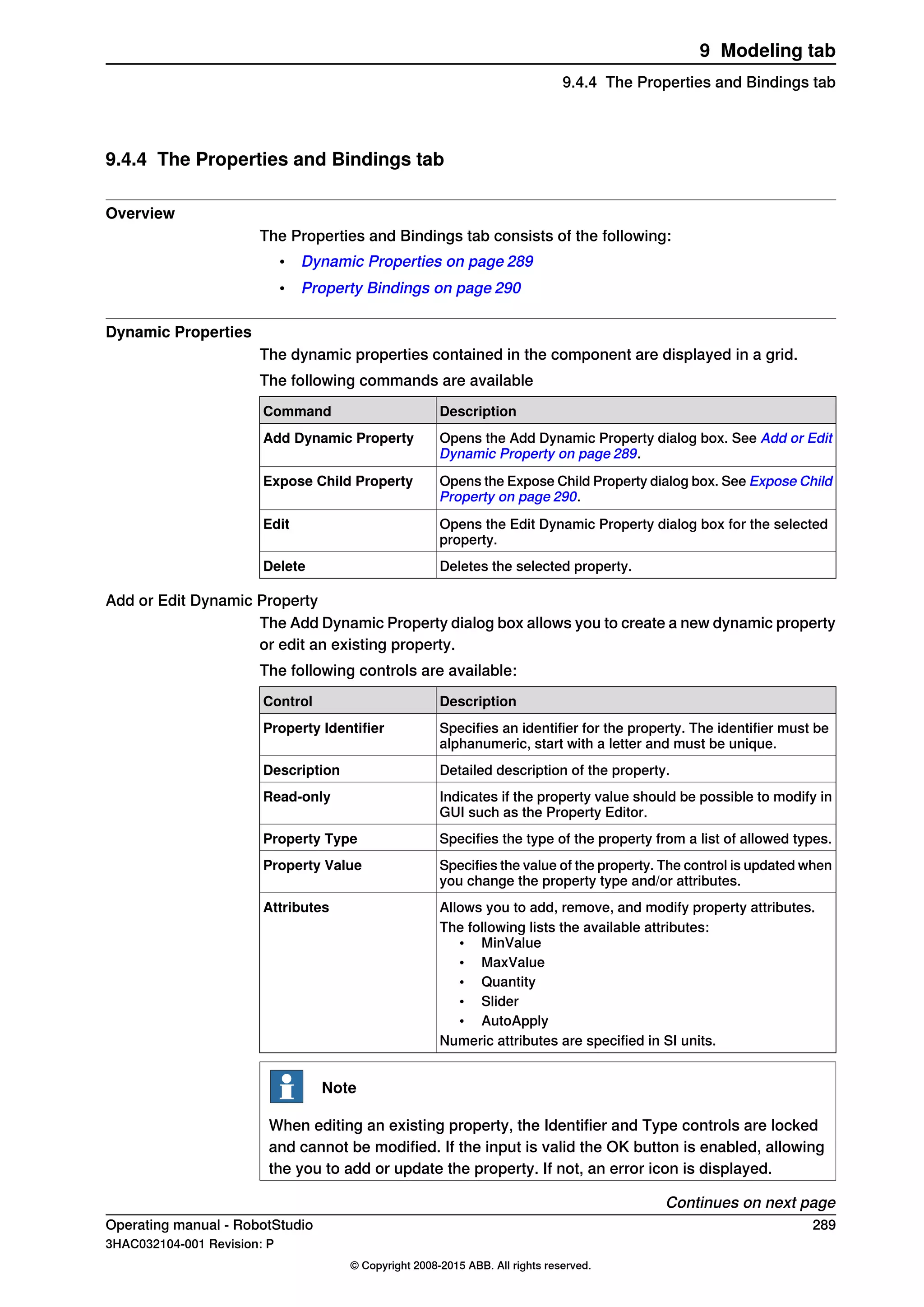
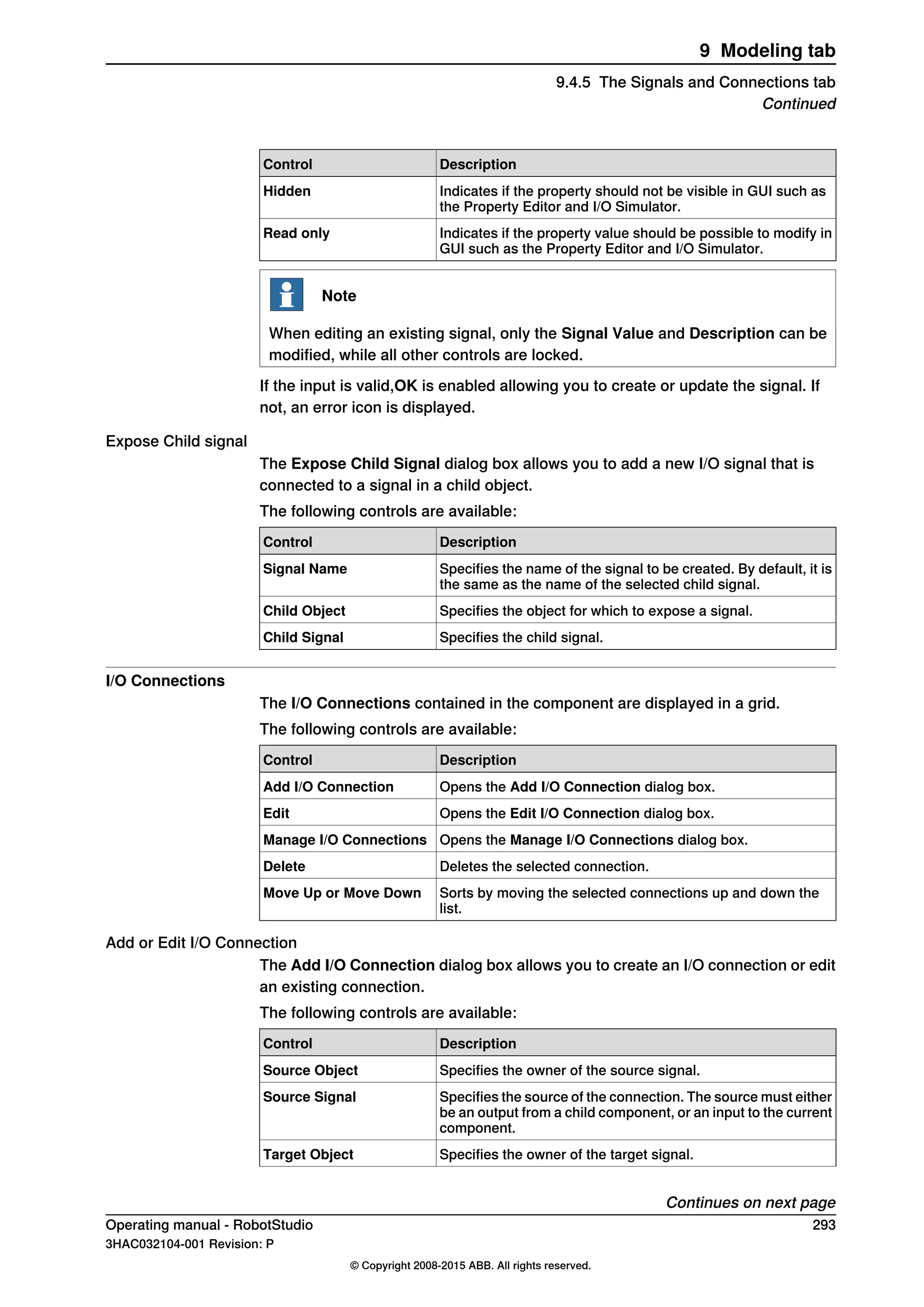
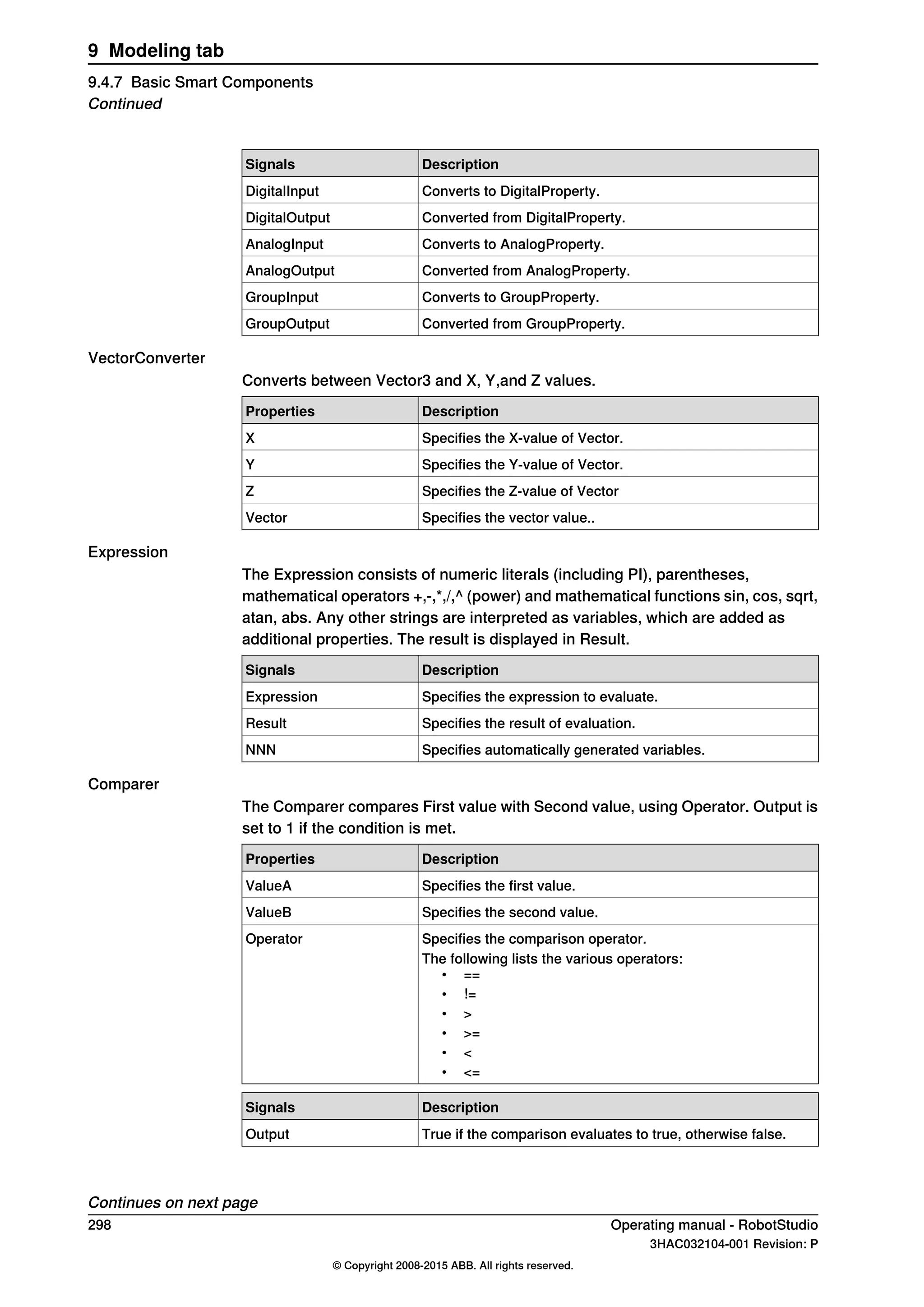
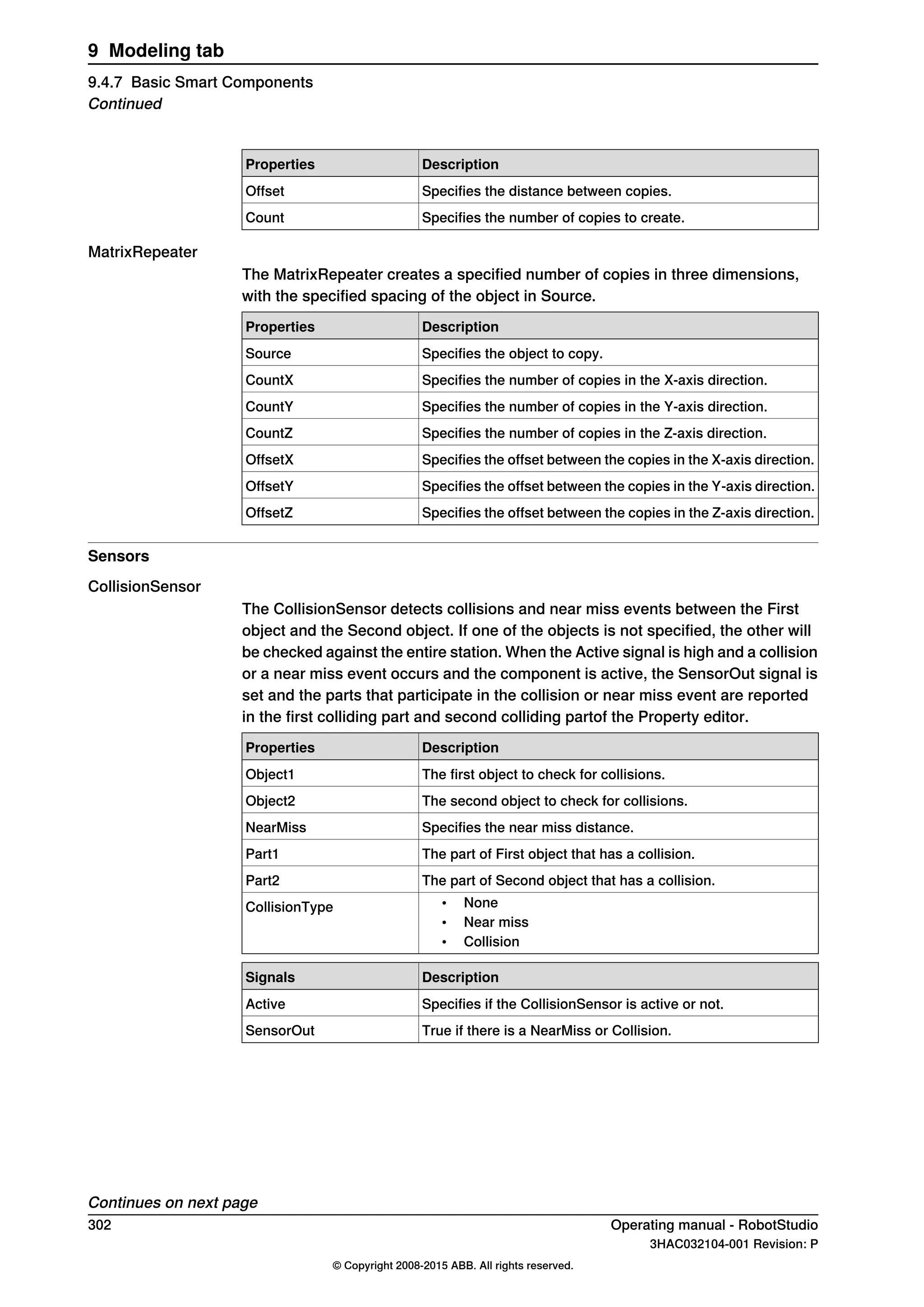
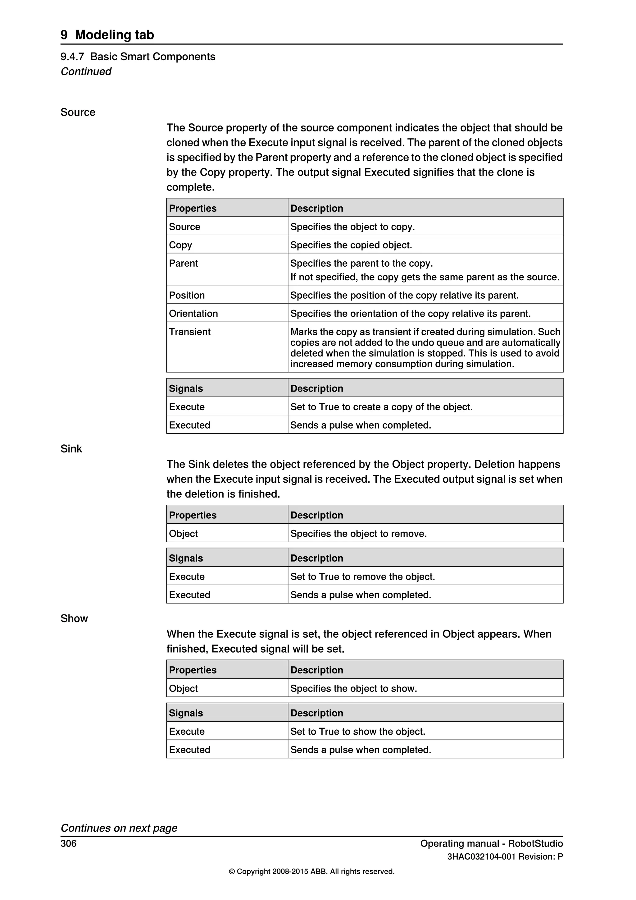
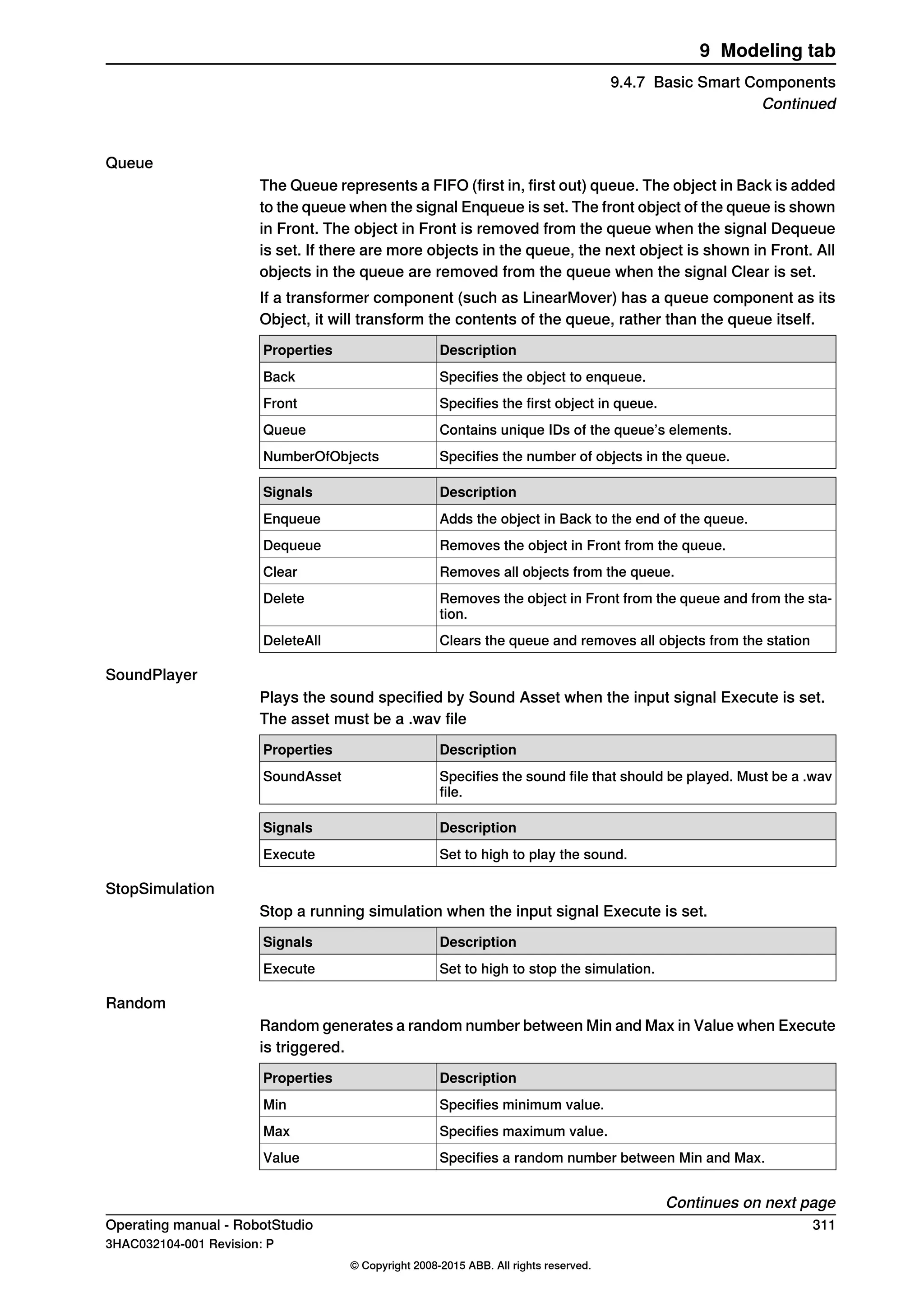
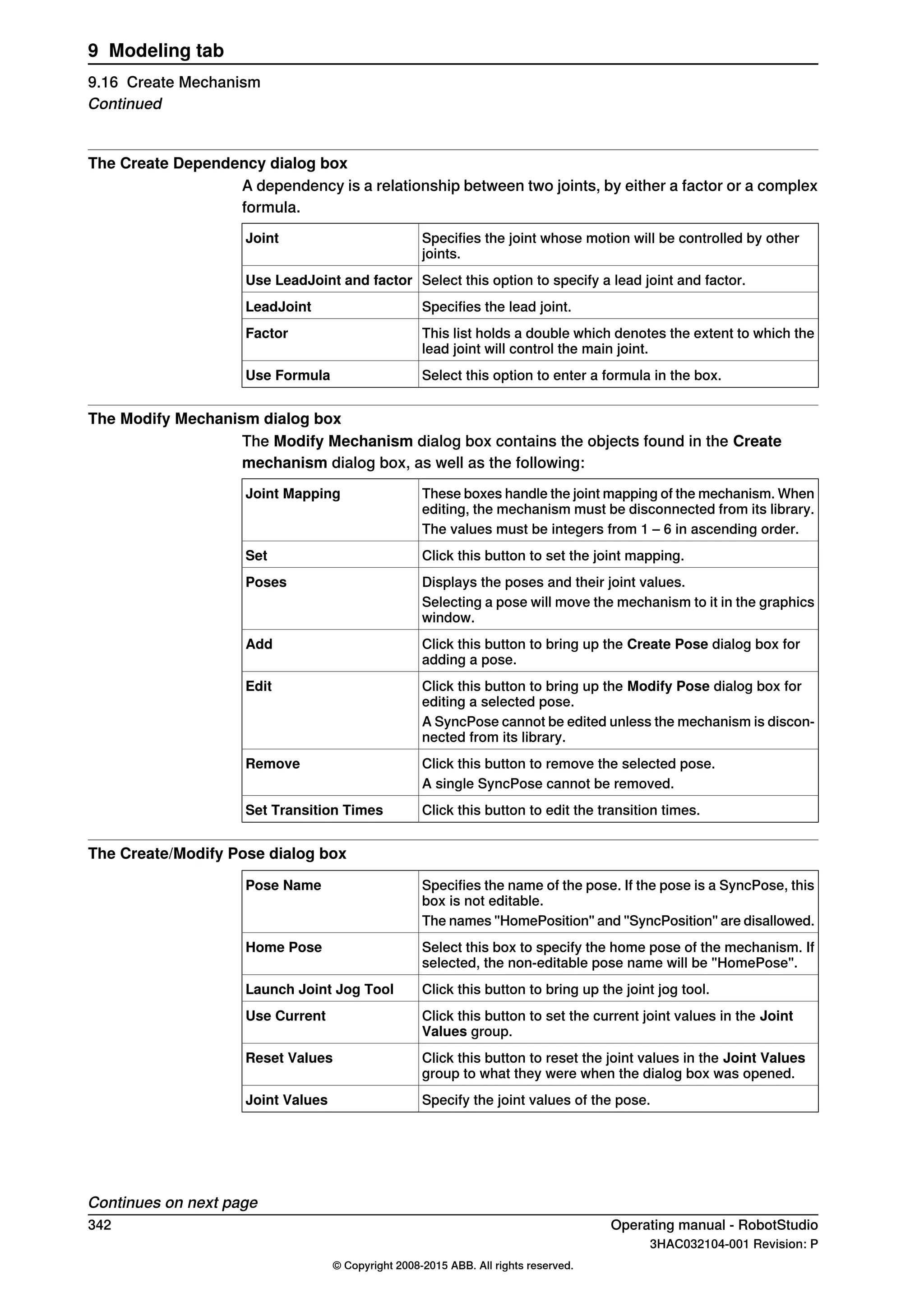
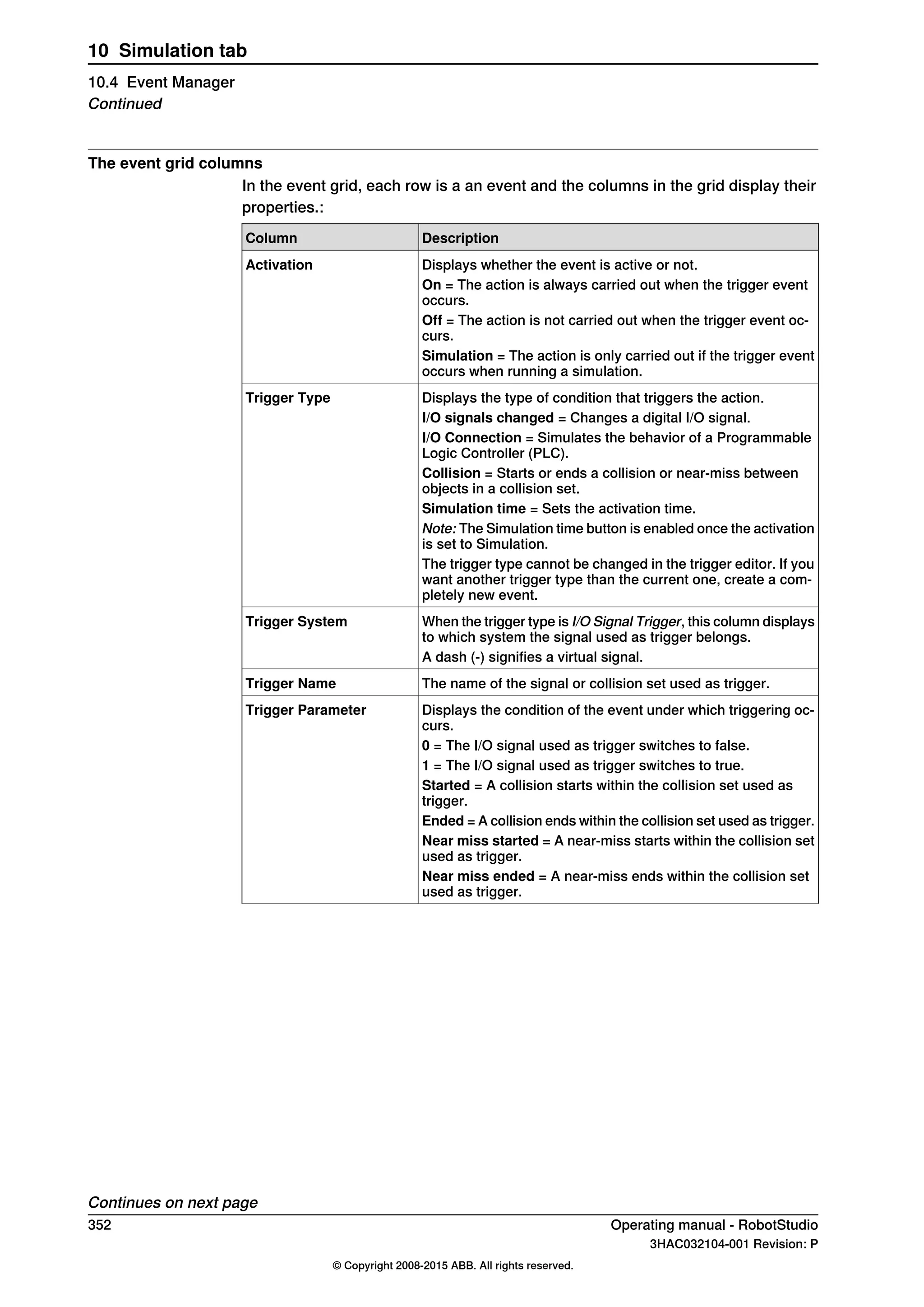
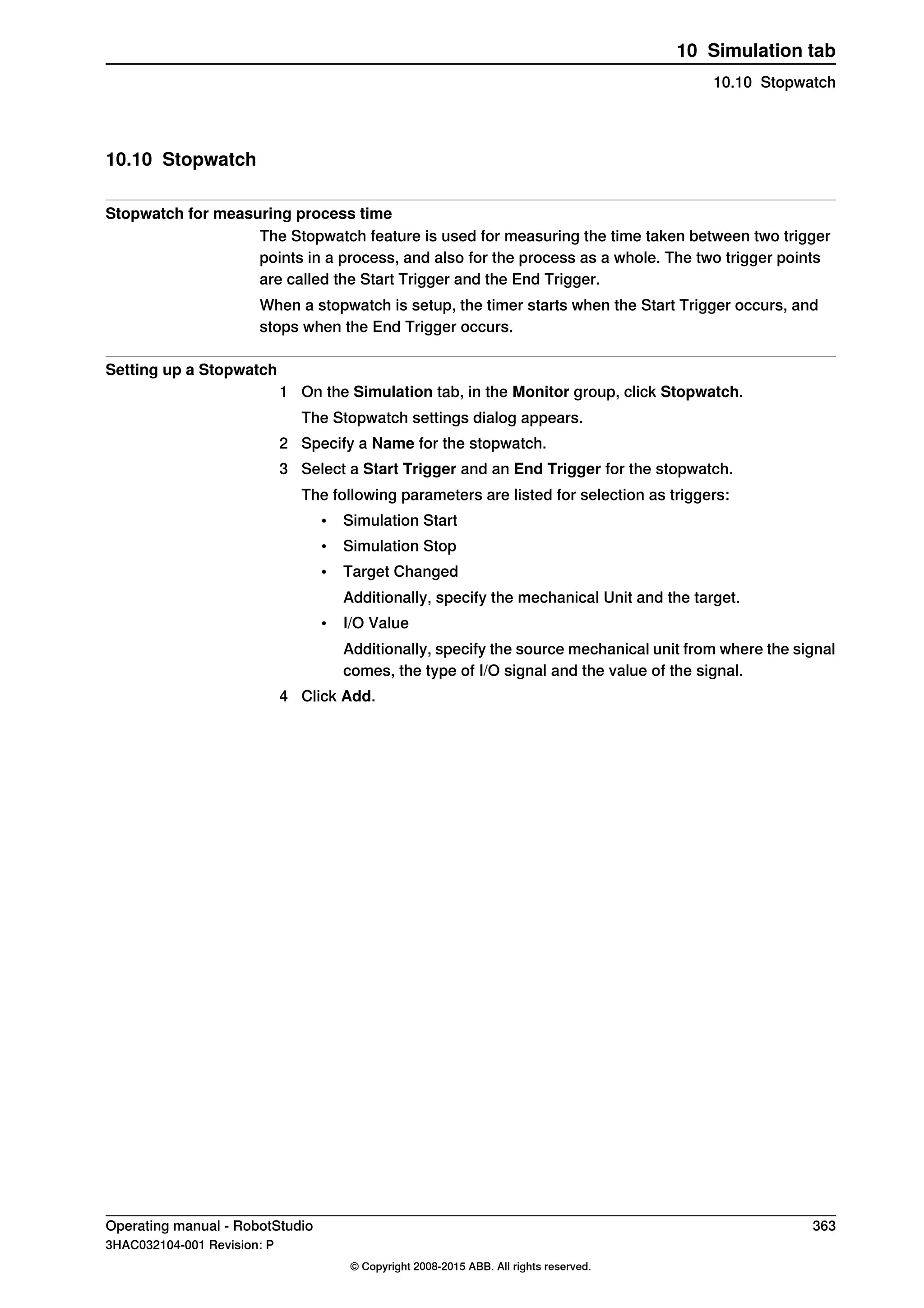
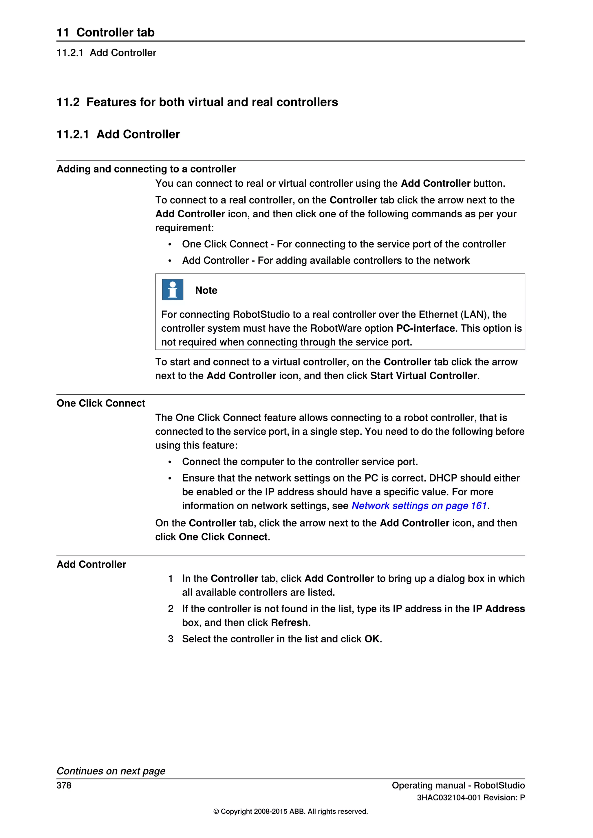
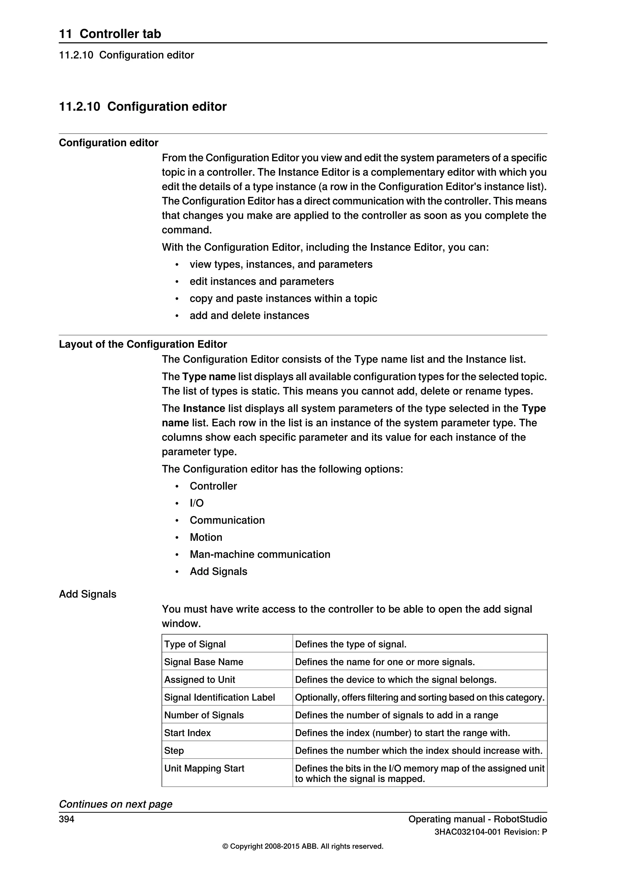
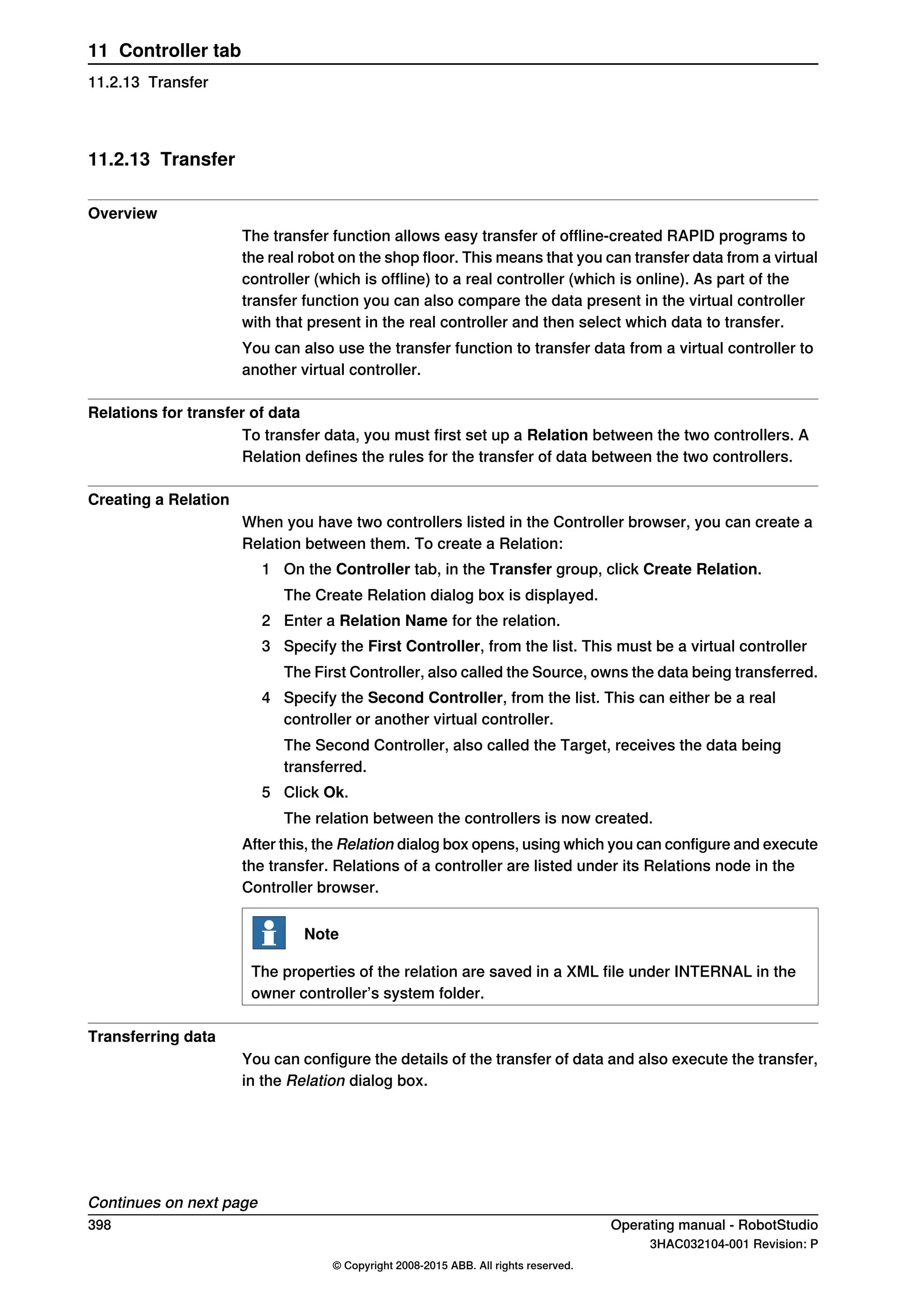
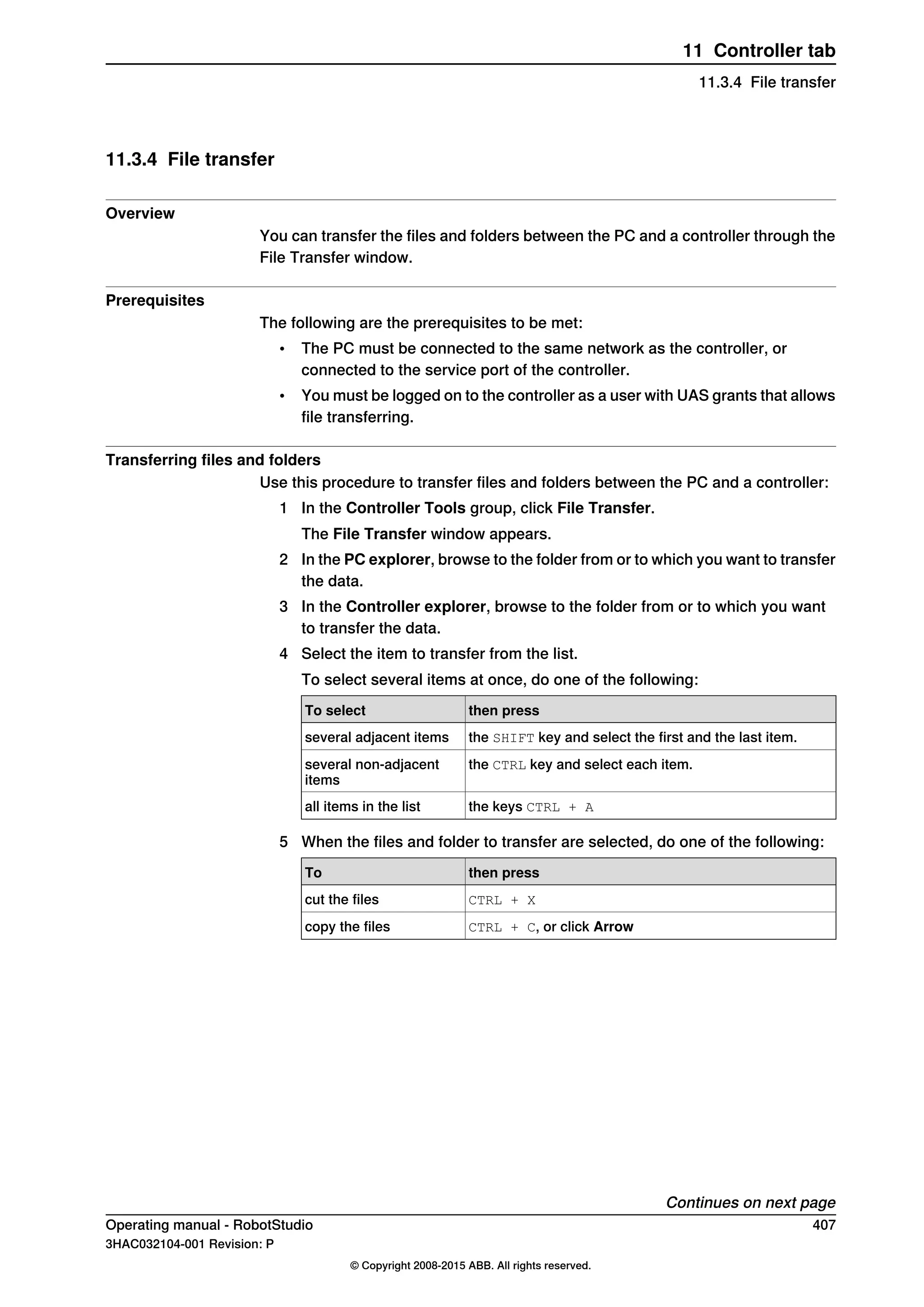
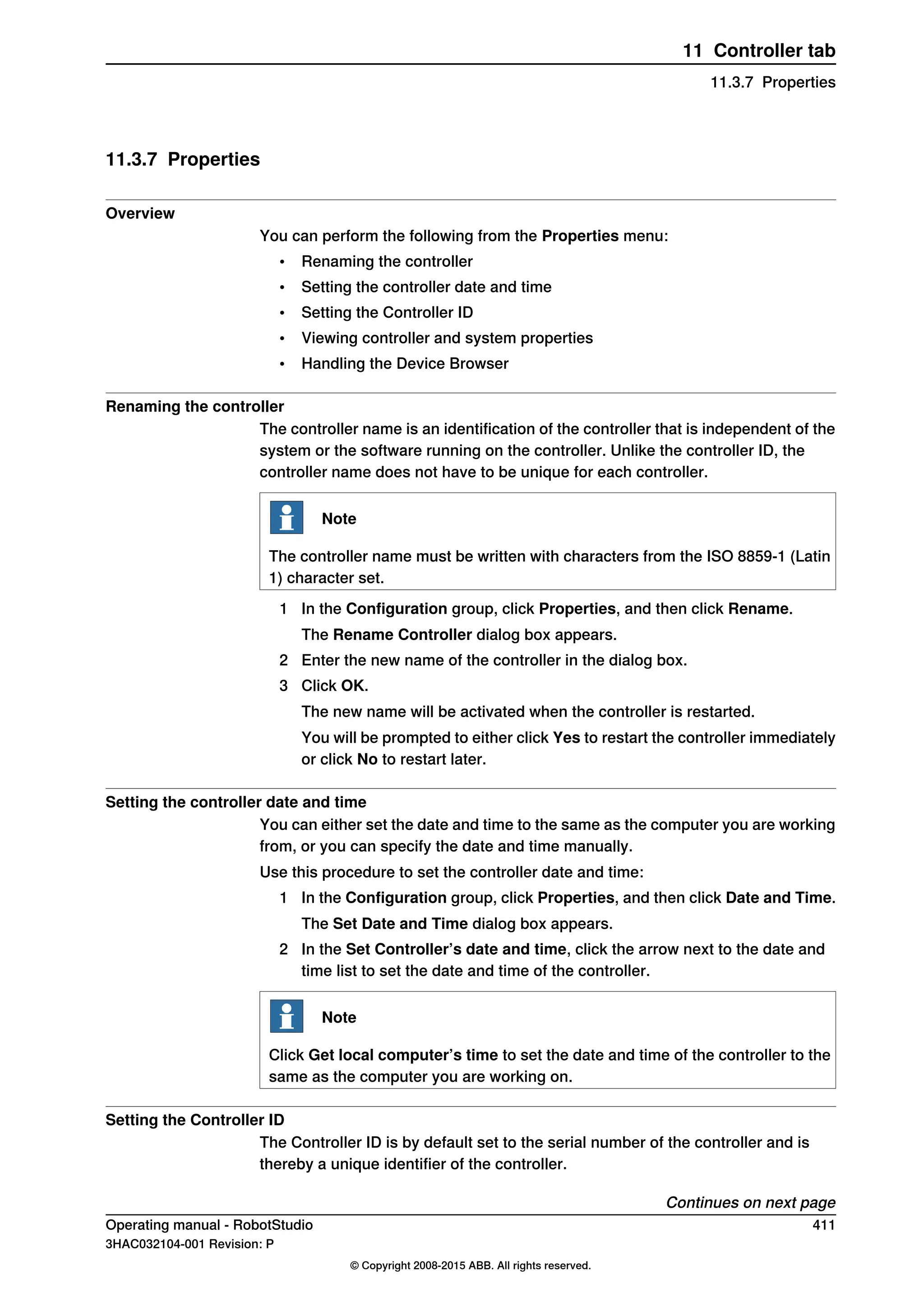
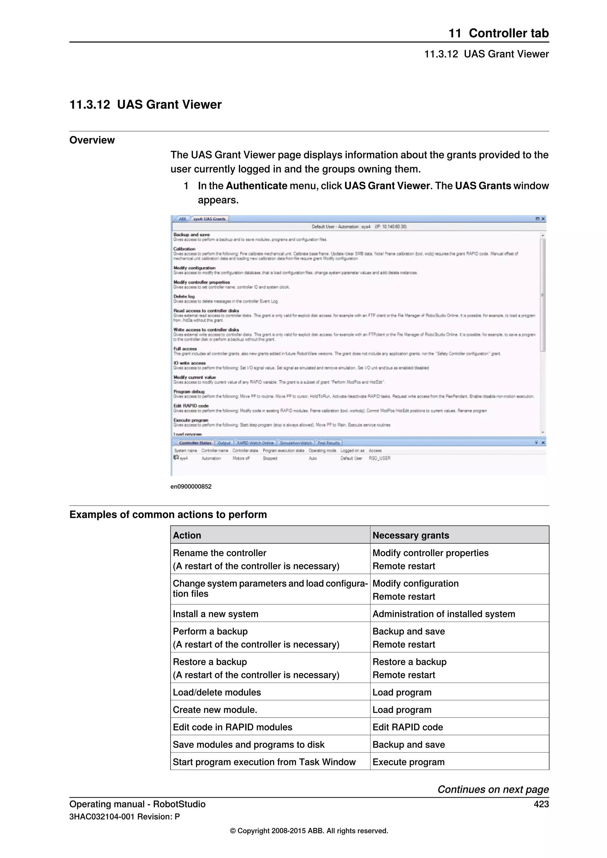
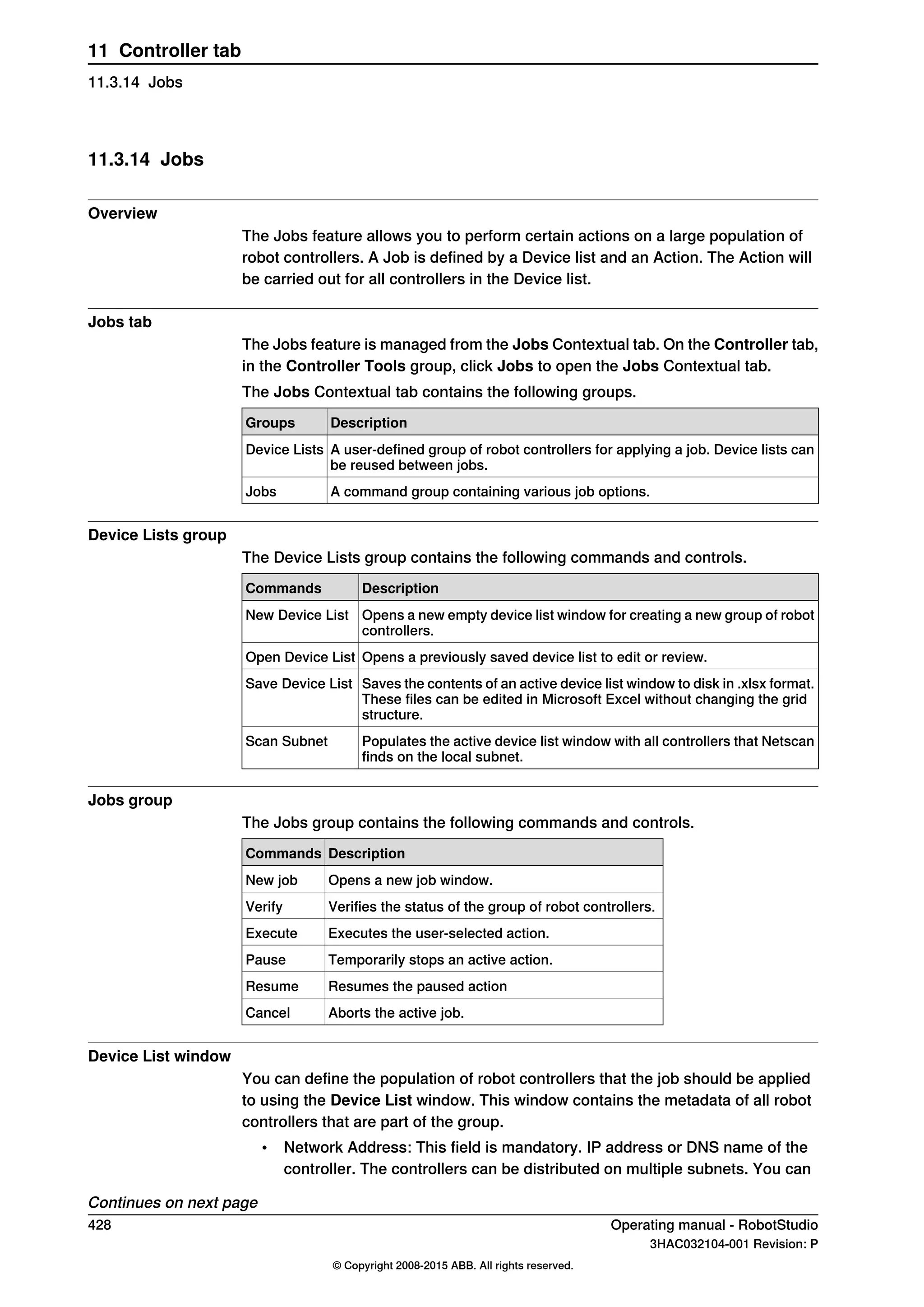
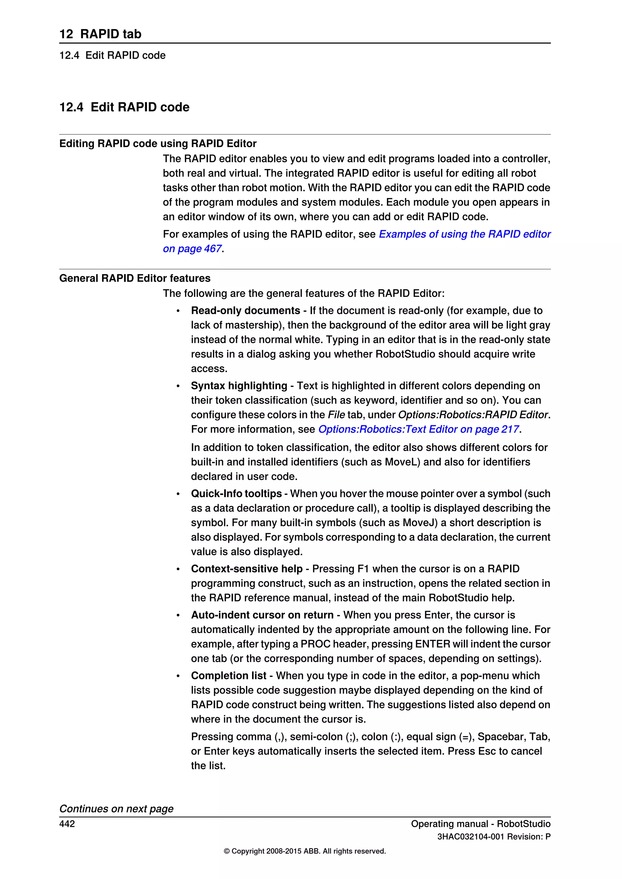
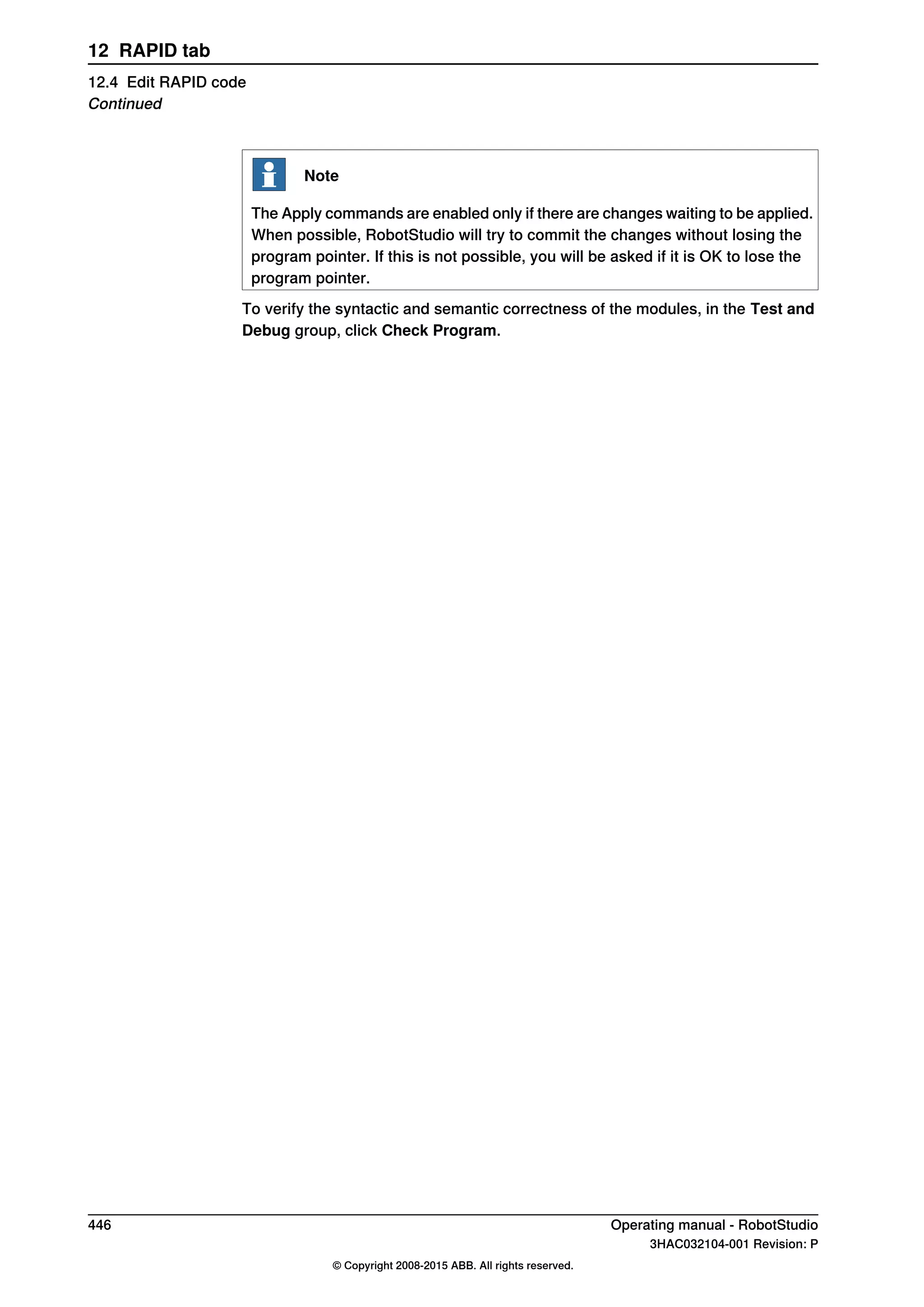
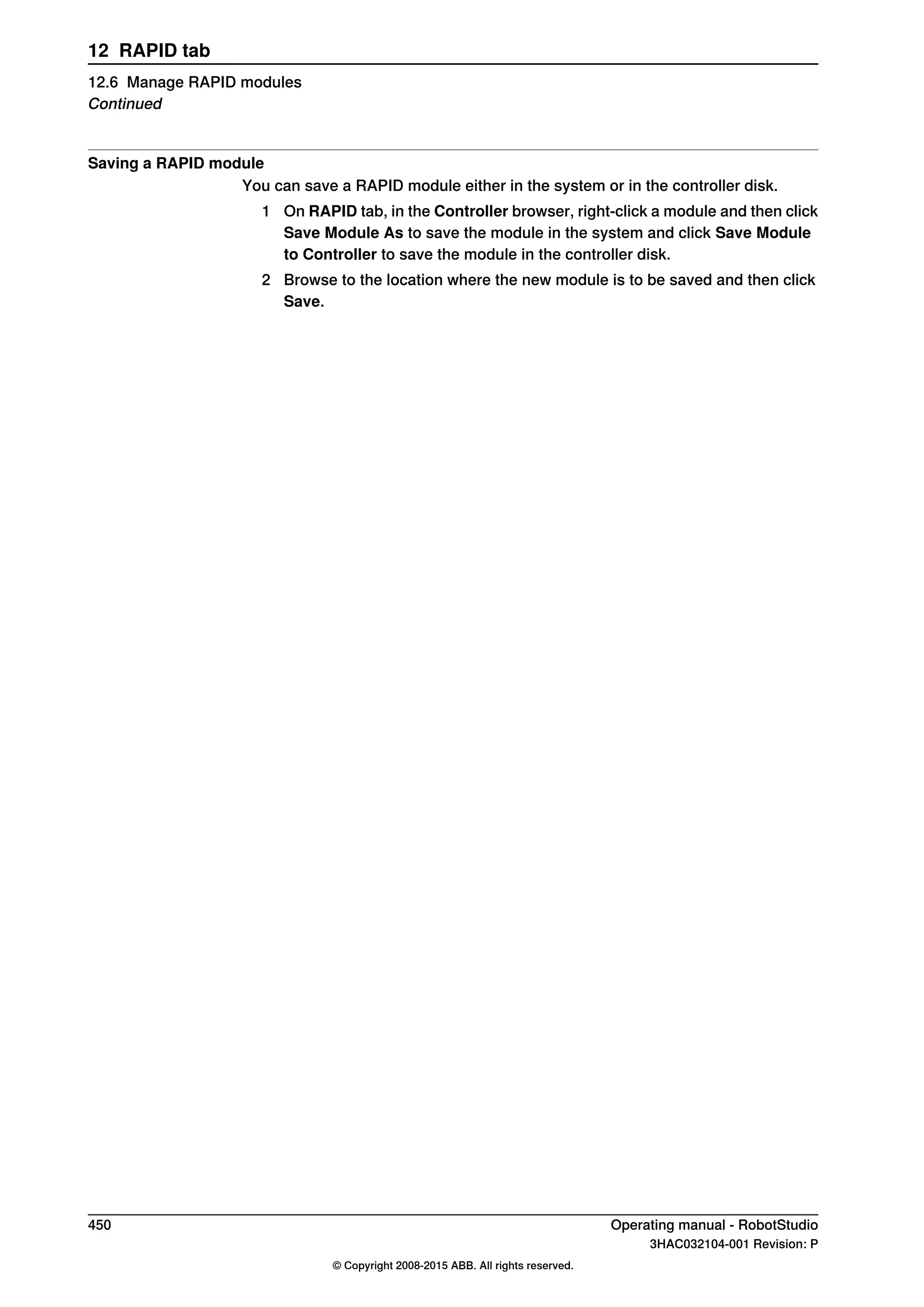
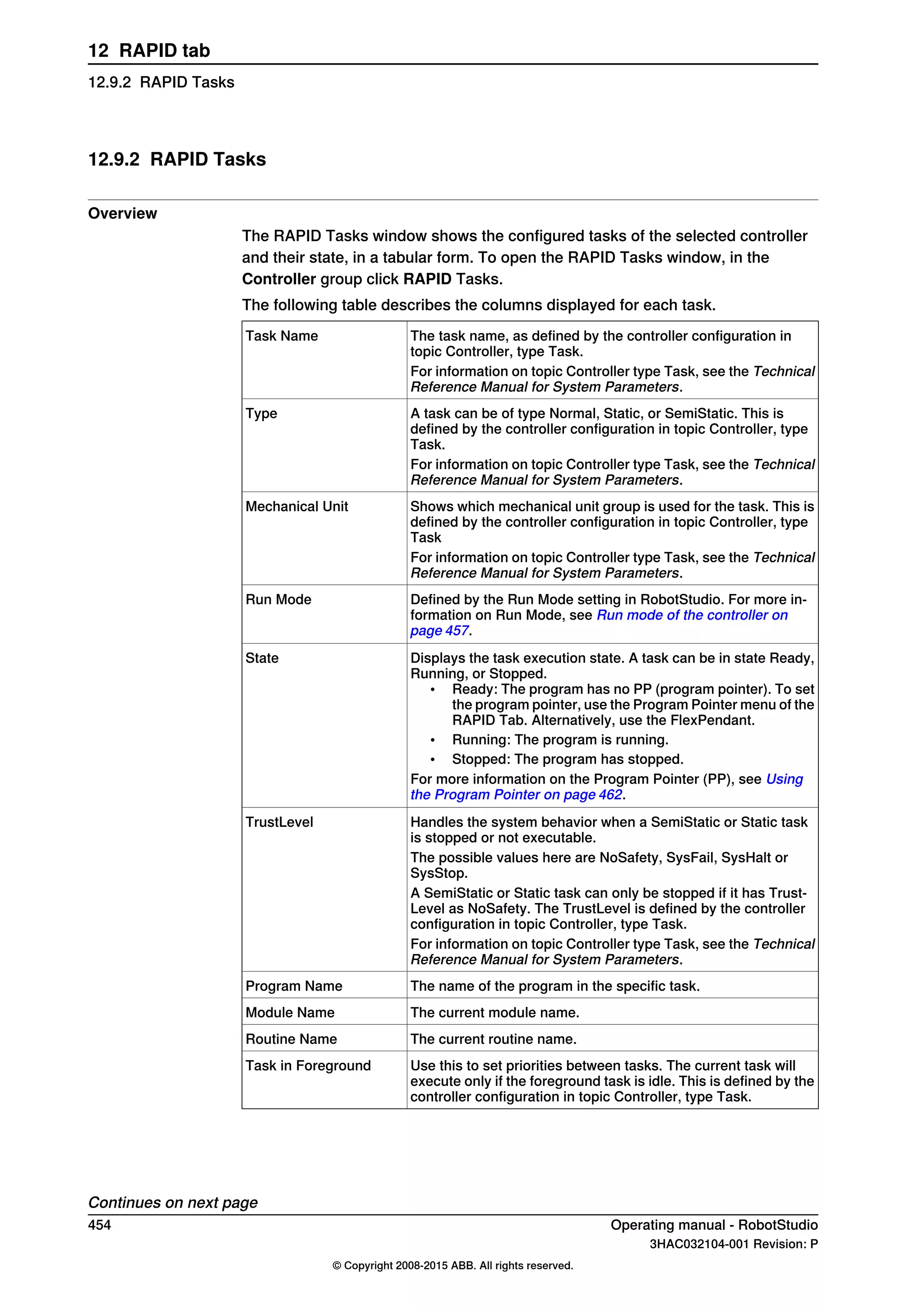
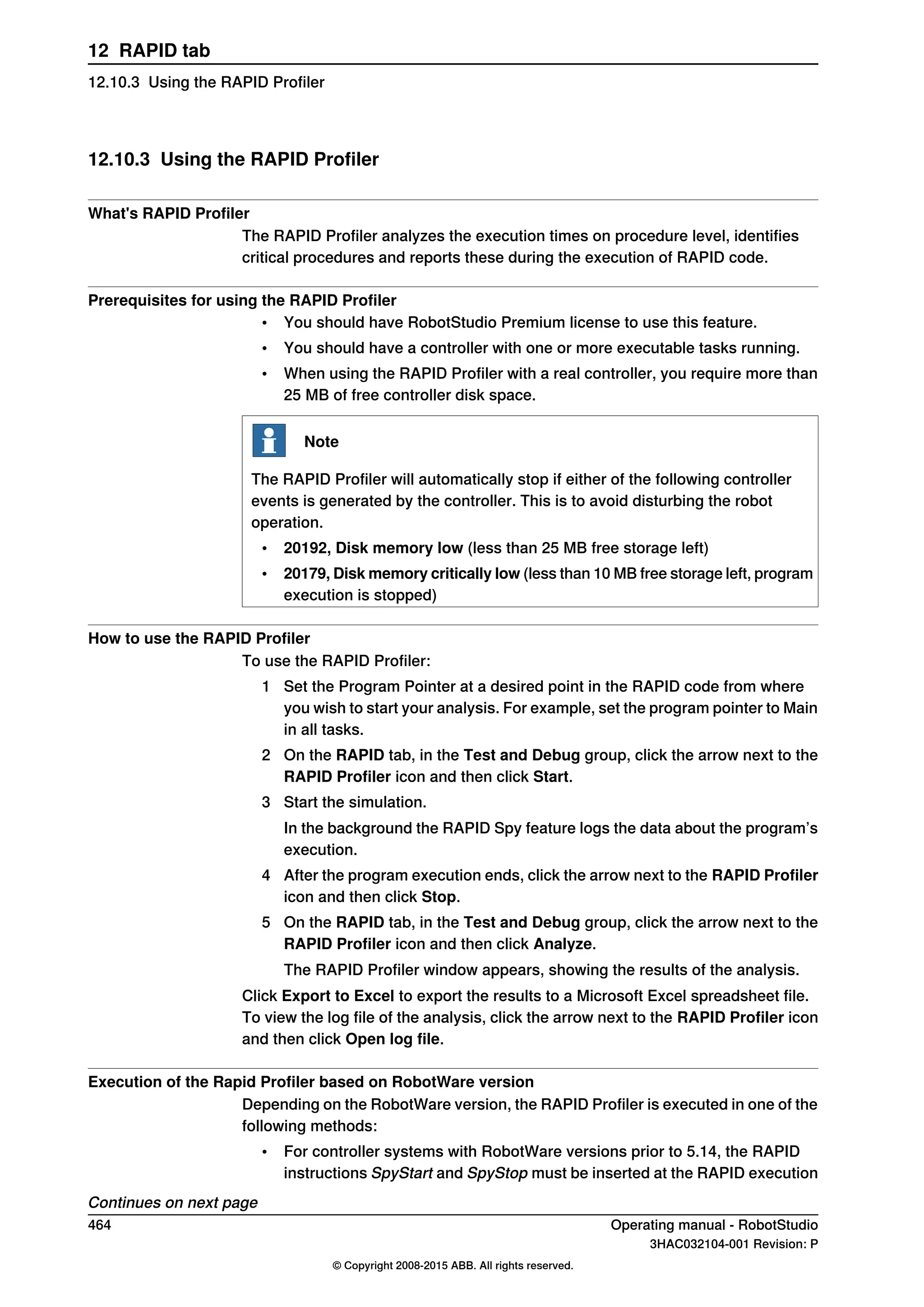
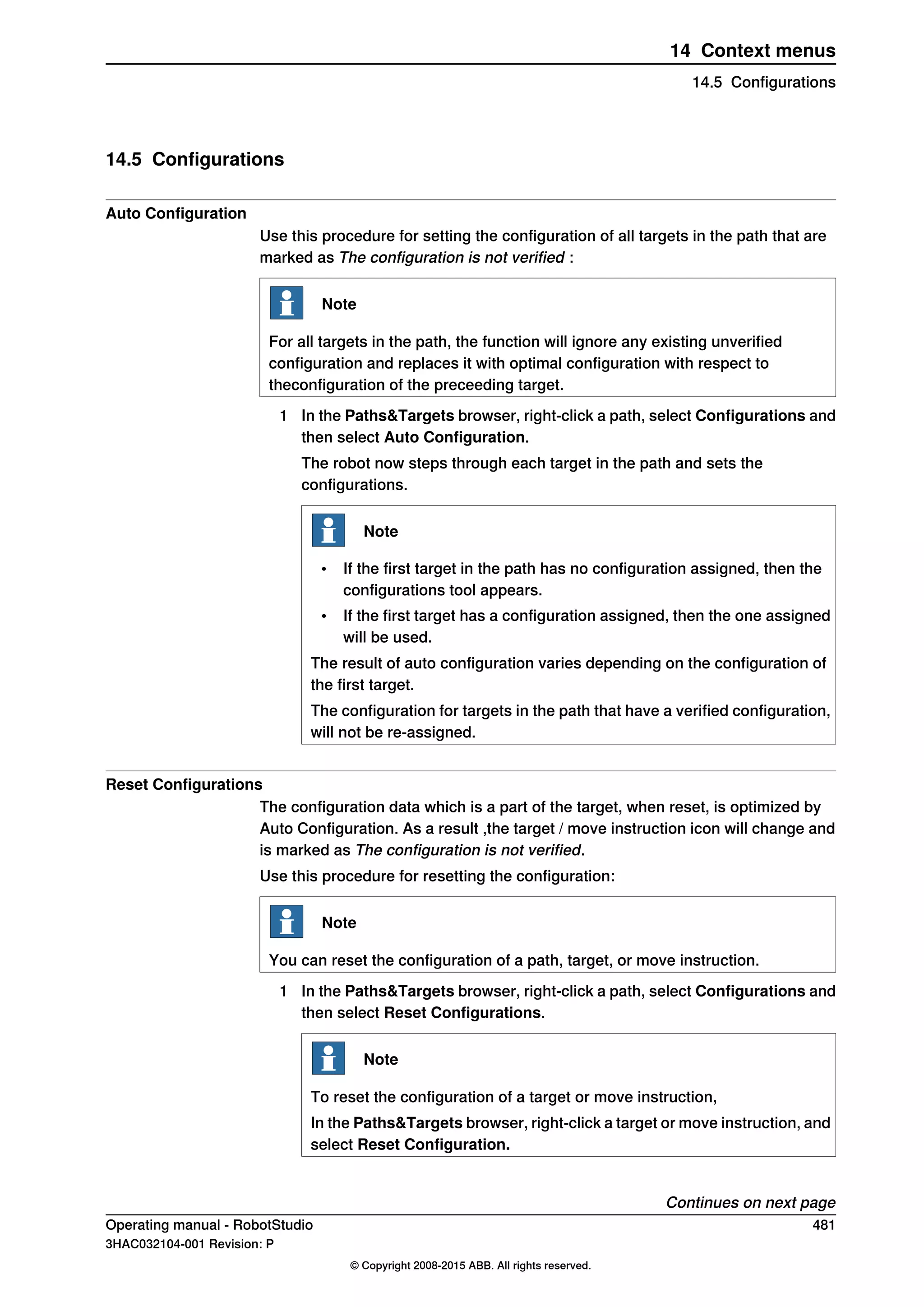
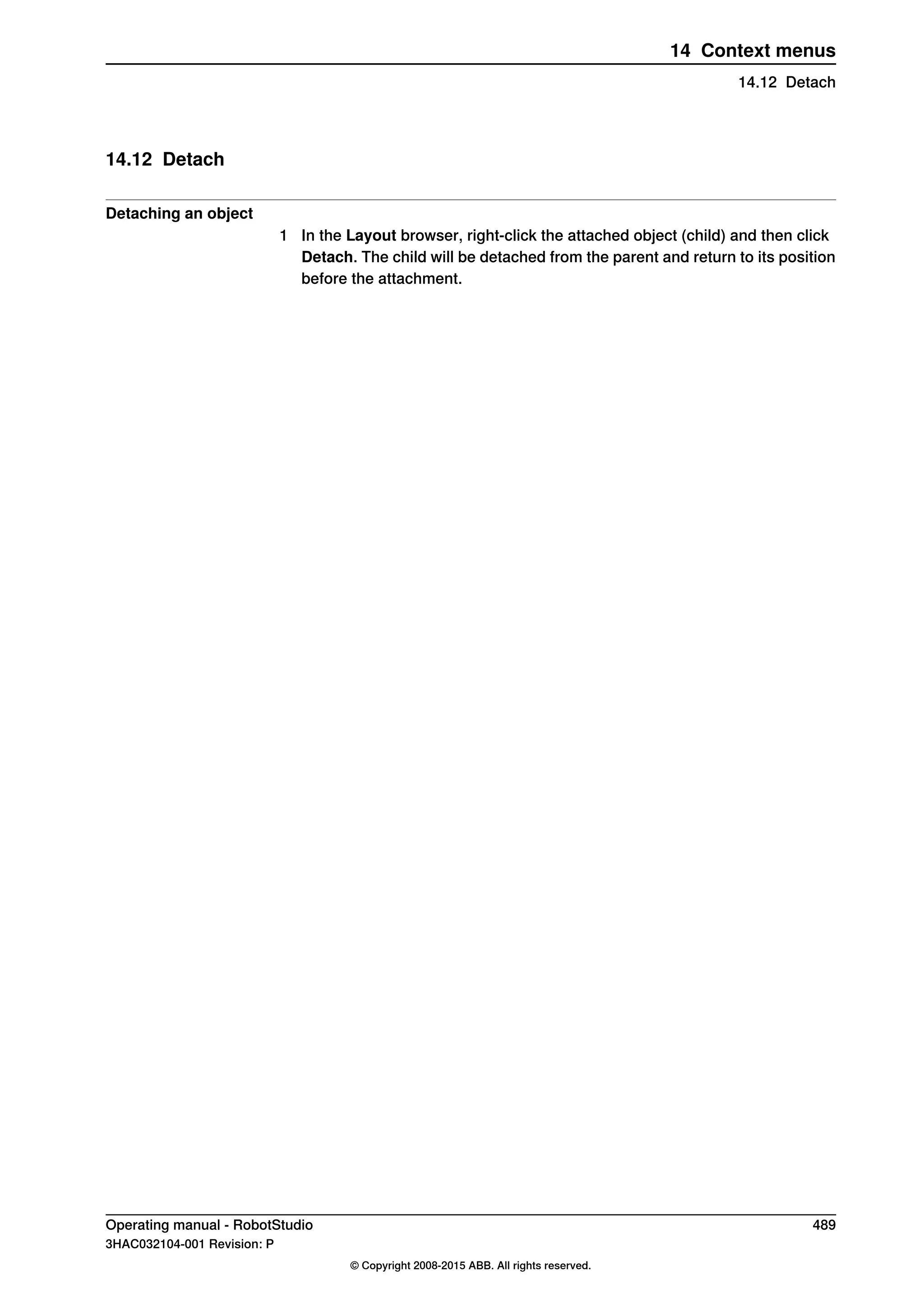
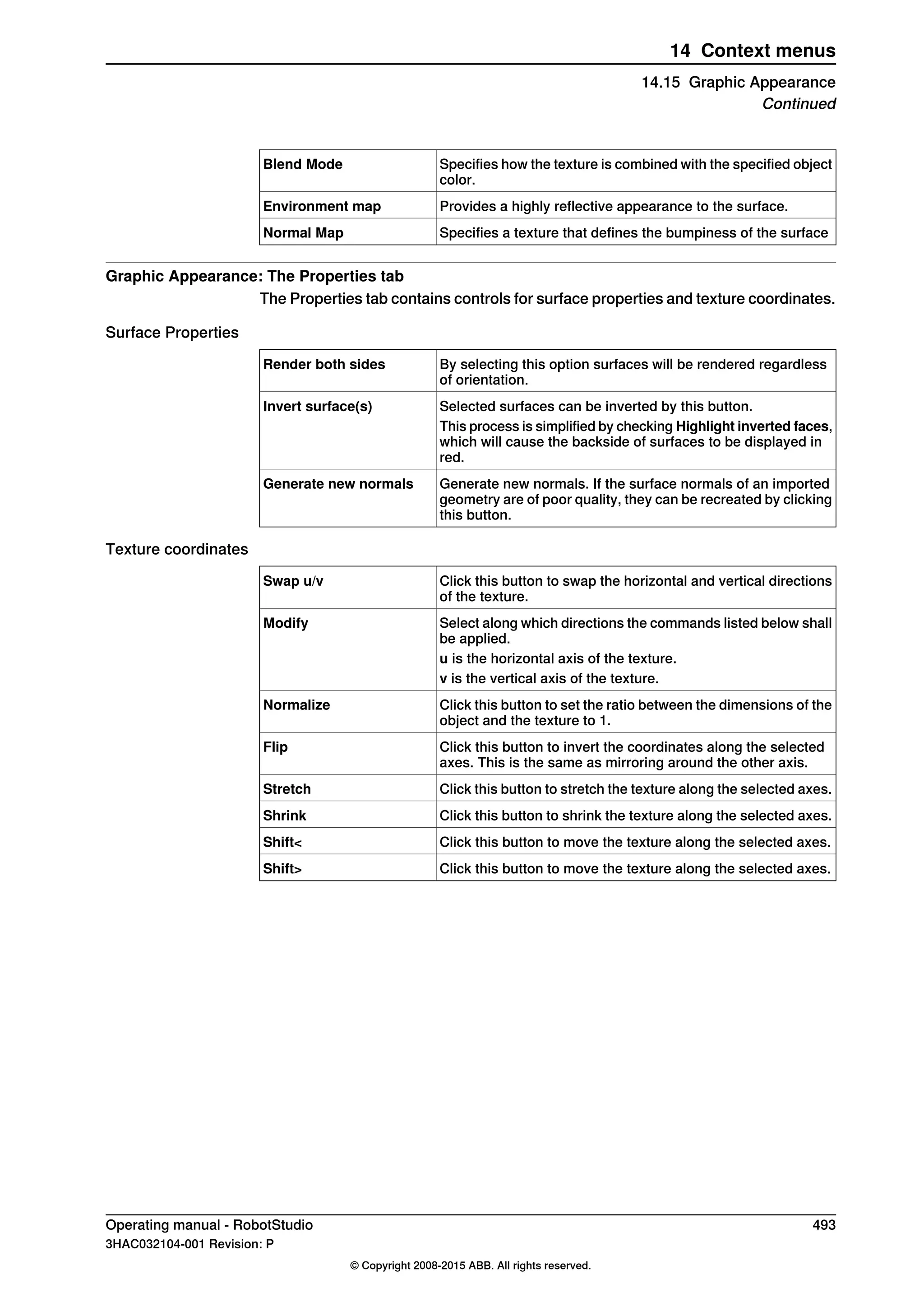
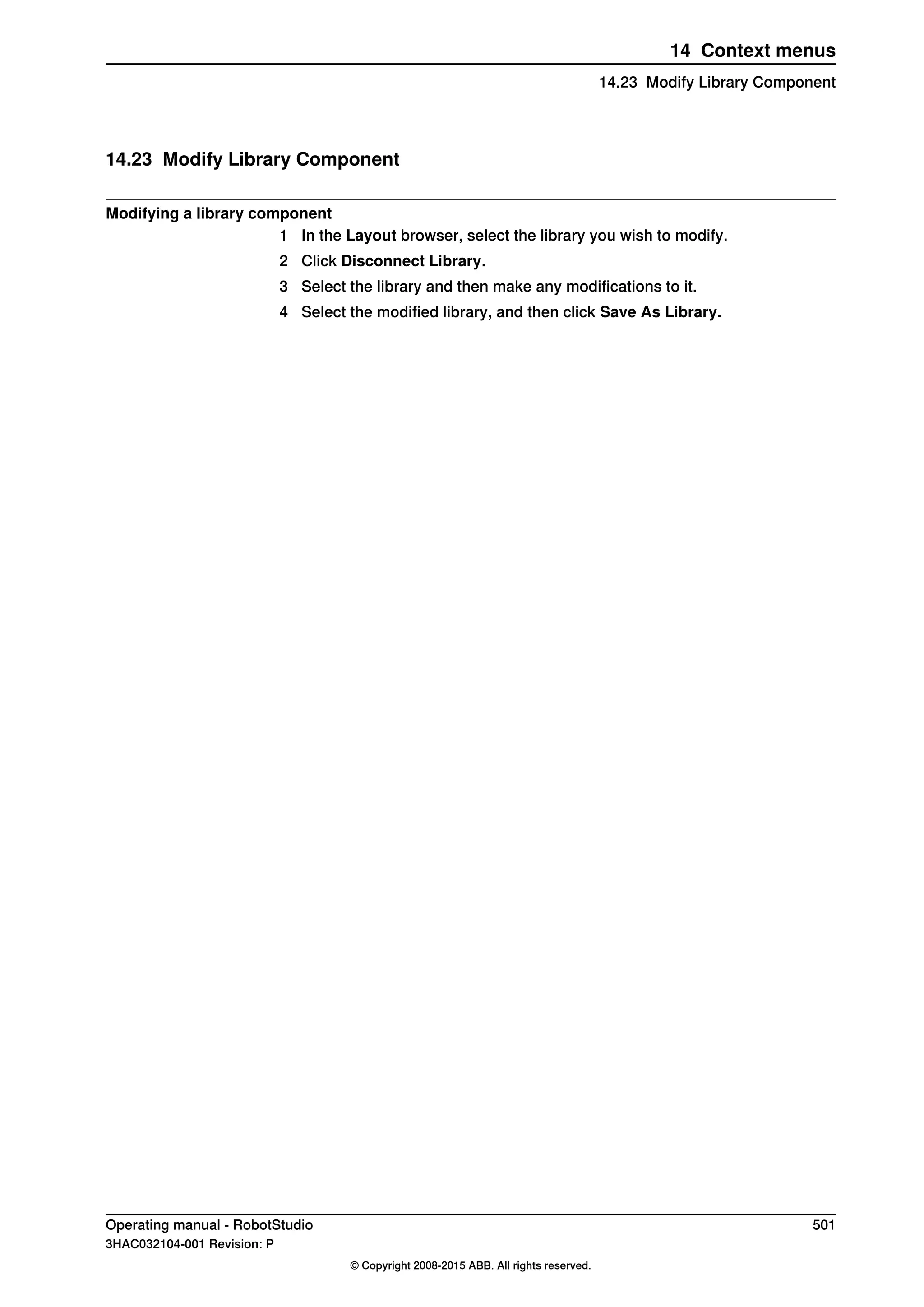
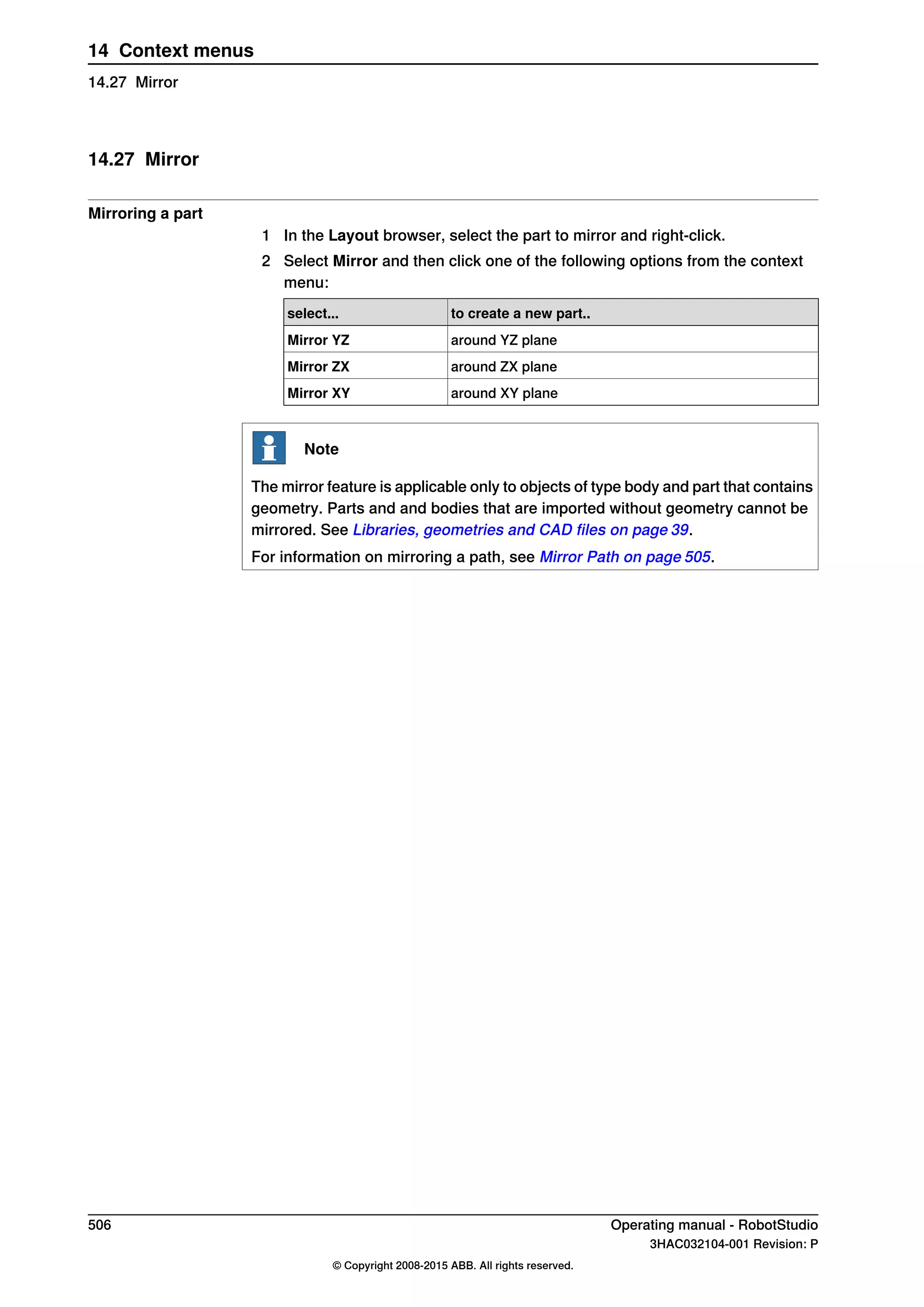
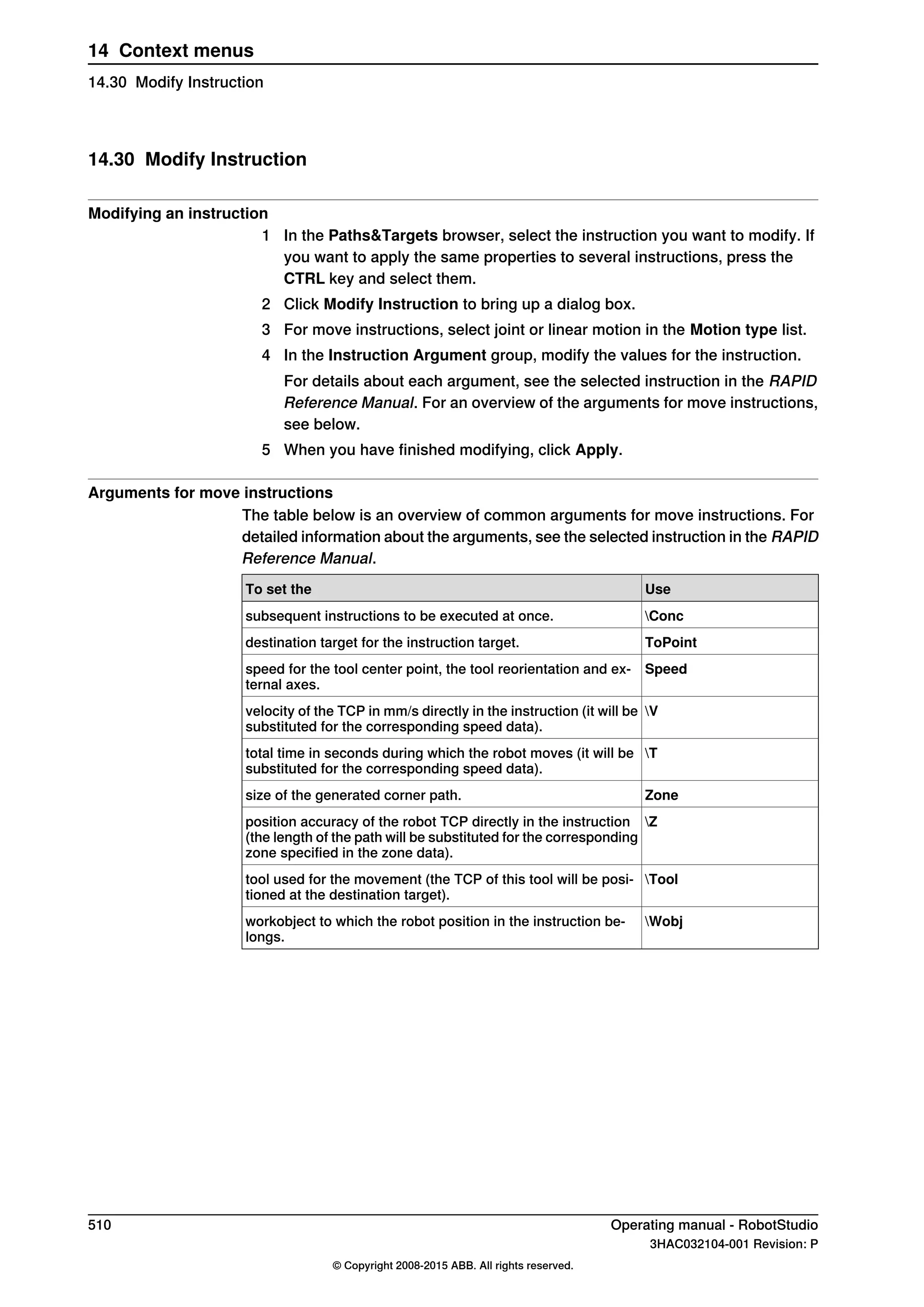
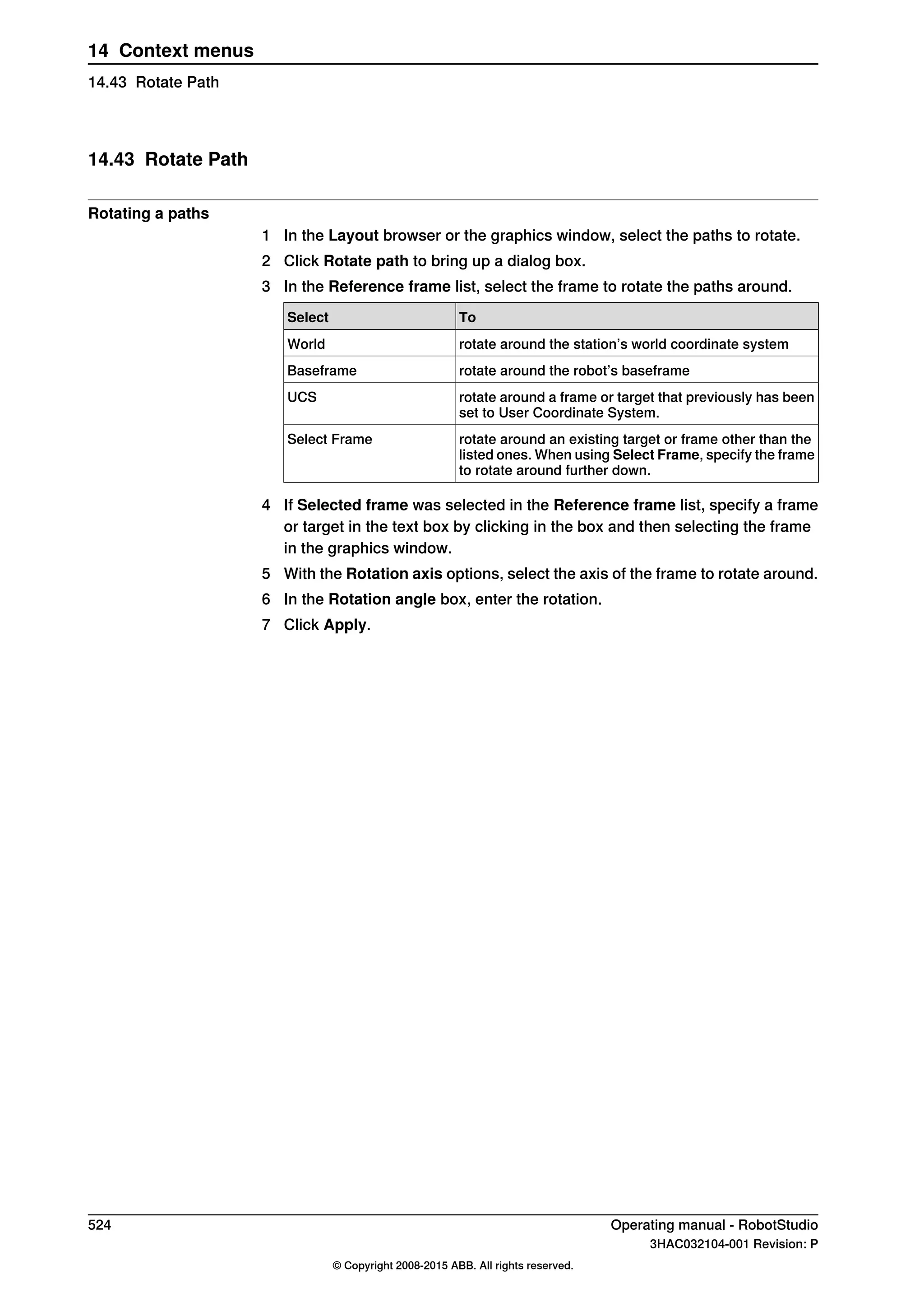
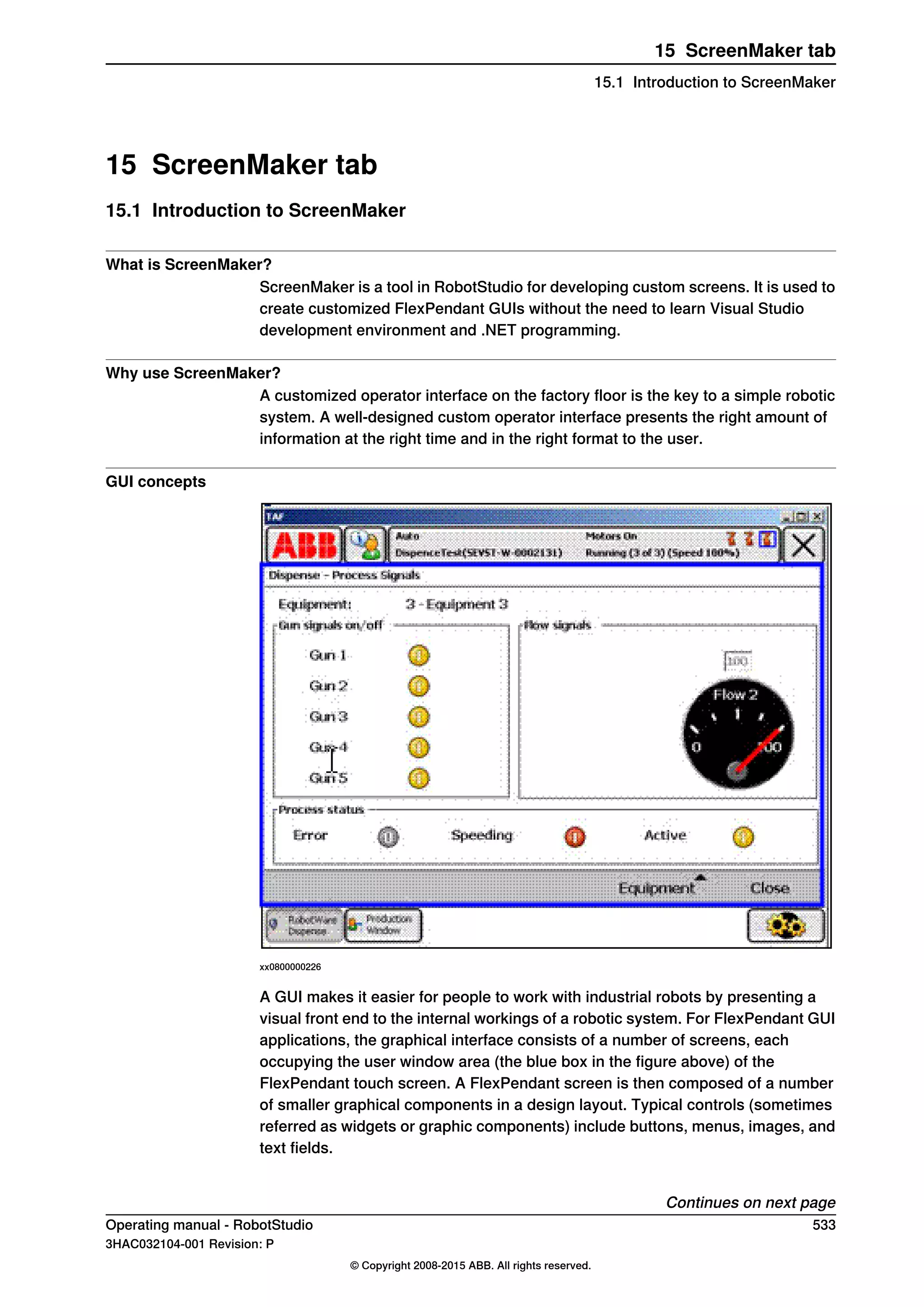
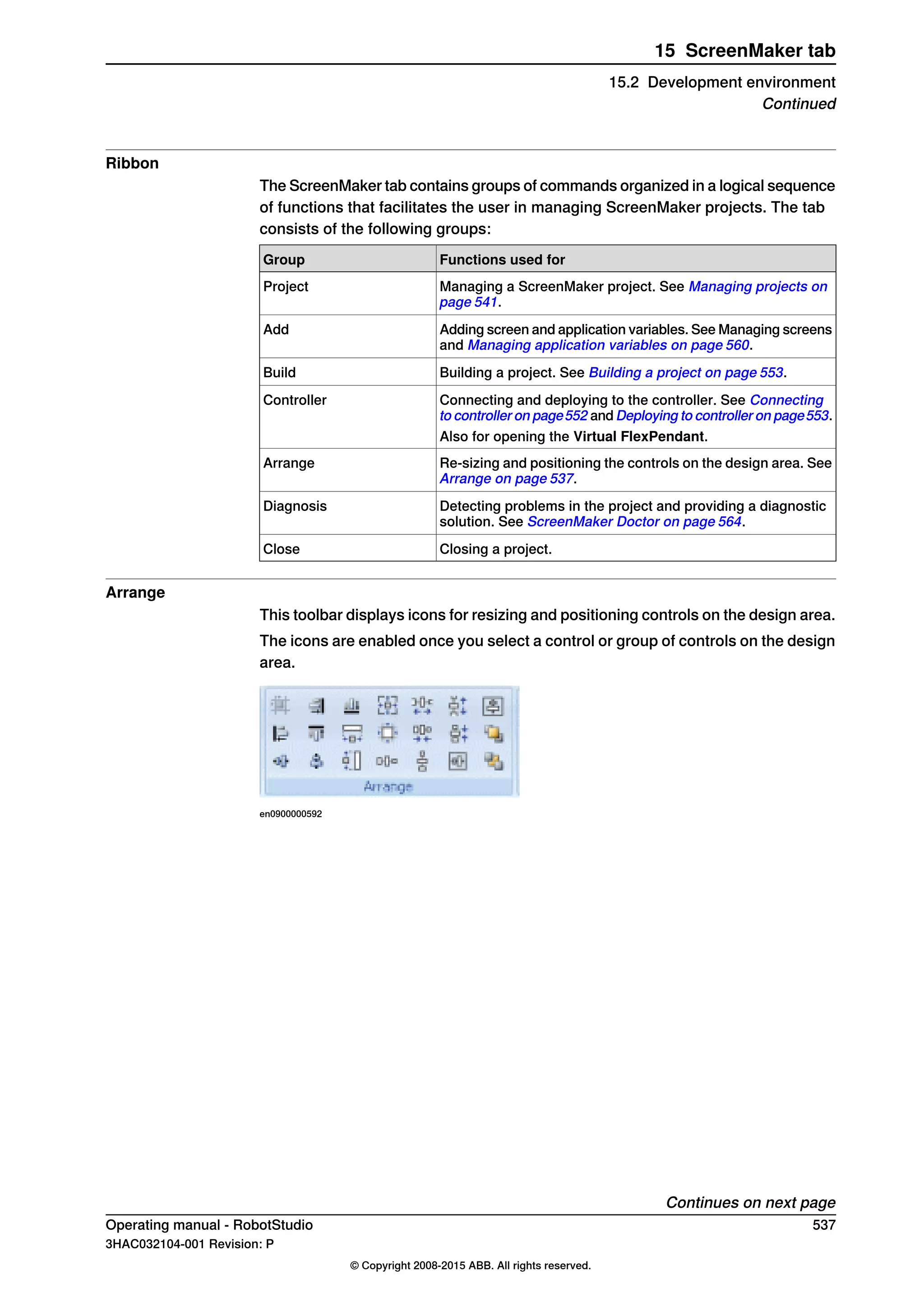
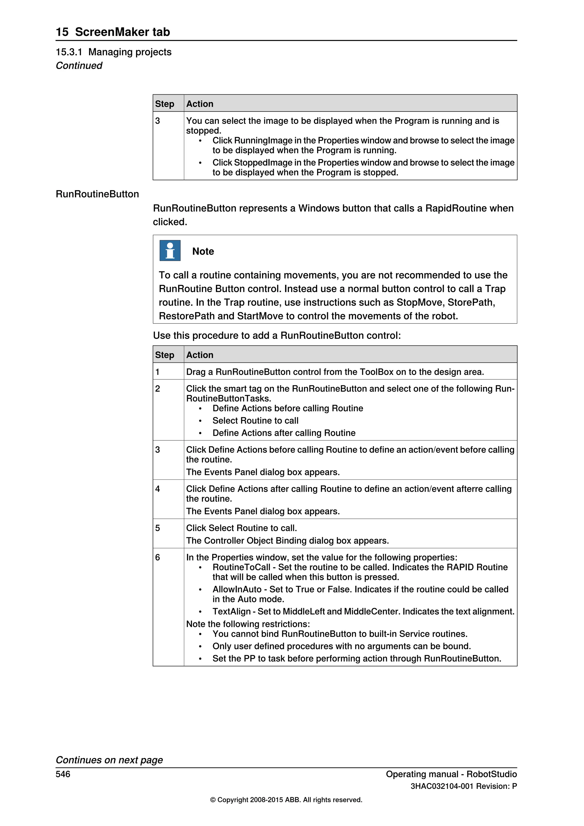
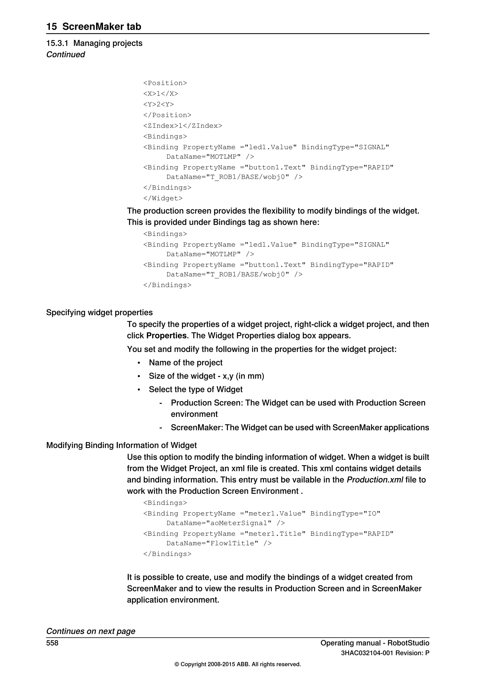
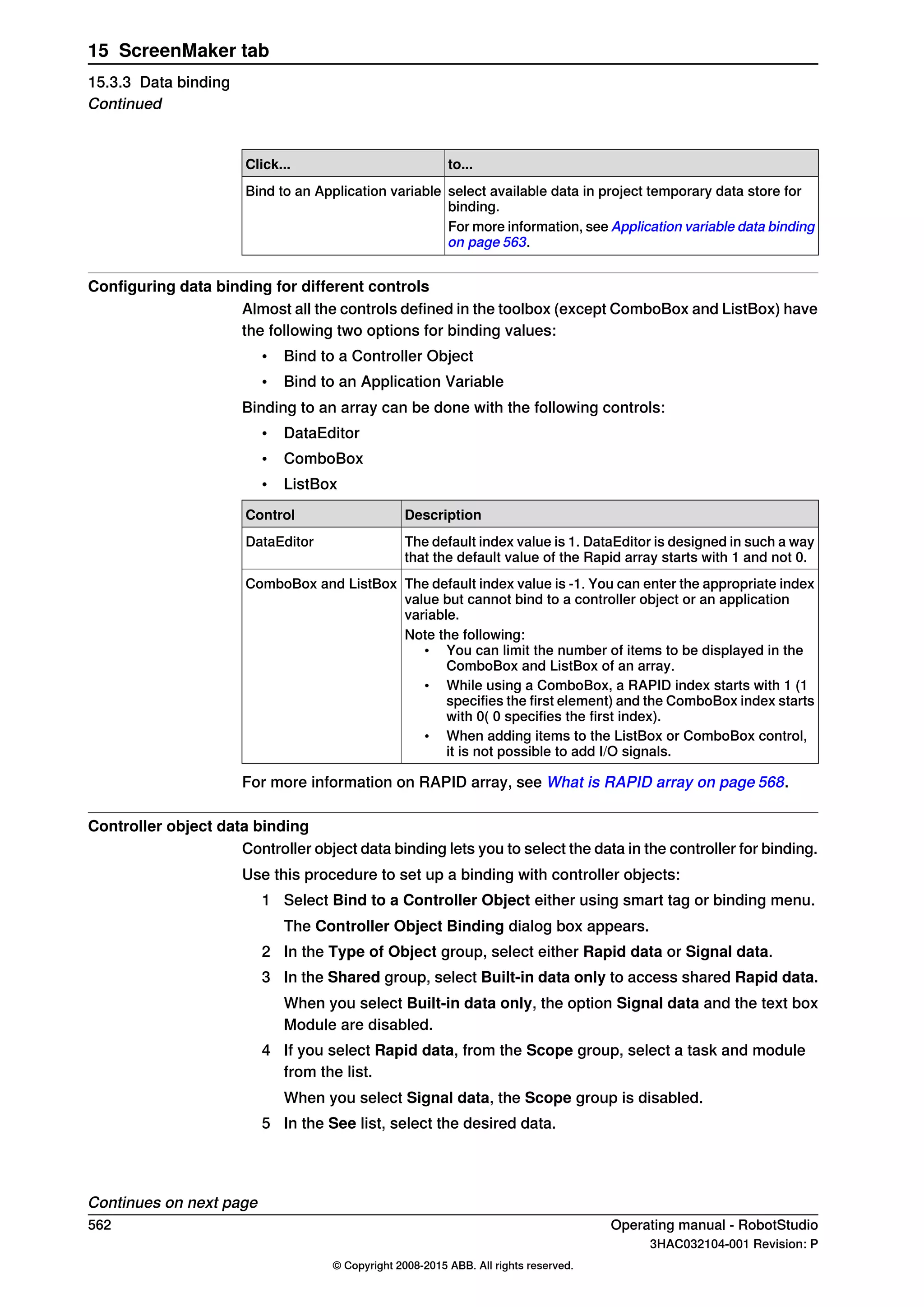
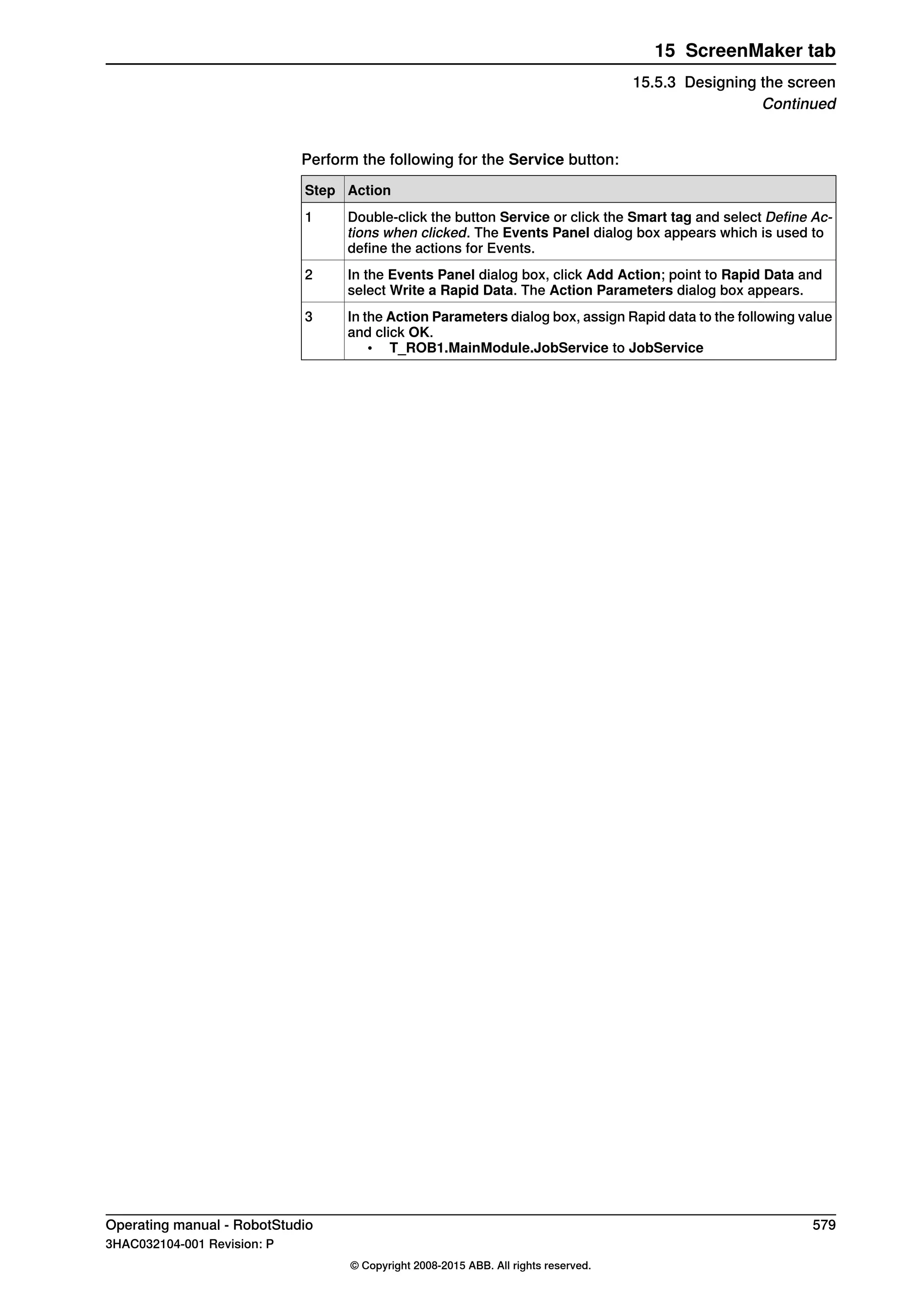
The robot’s axis configurations are denoted by a series of four integers, specifying
in which quadrant of a full revolution significant axes are located. The quadrants
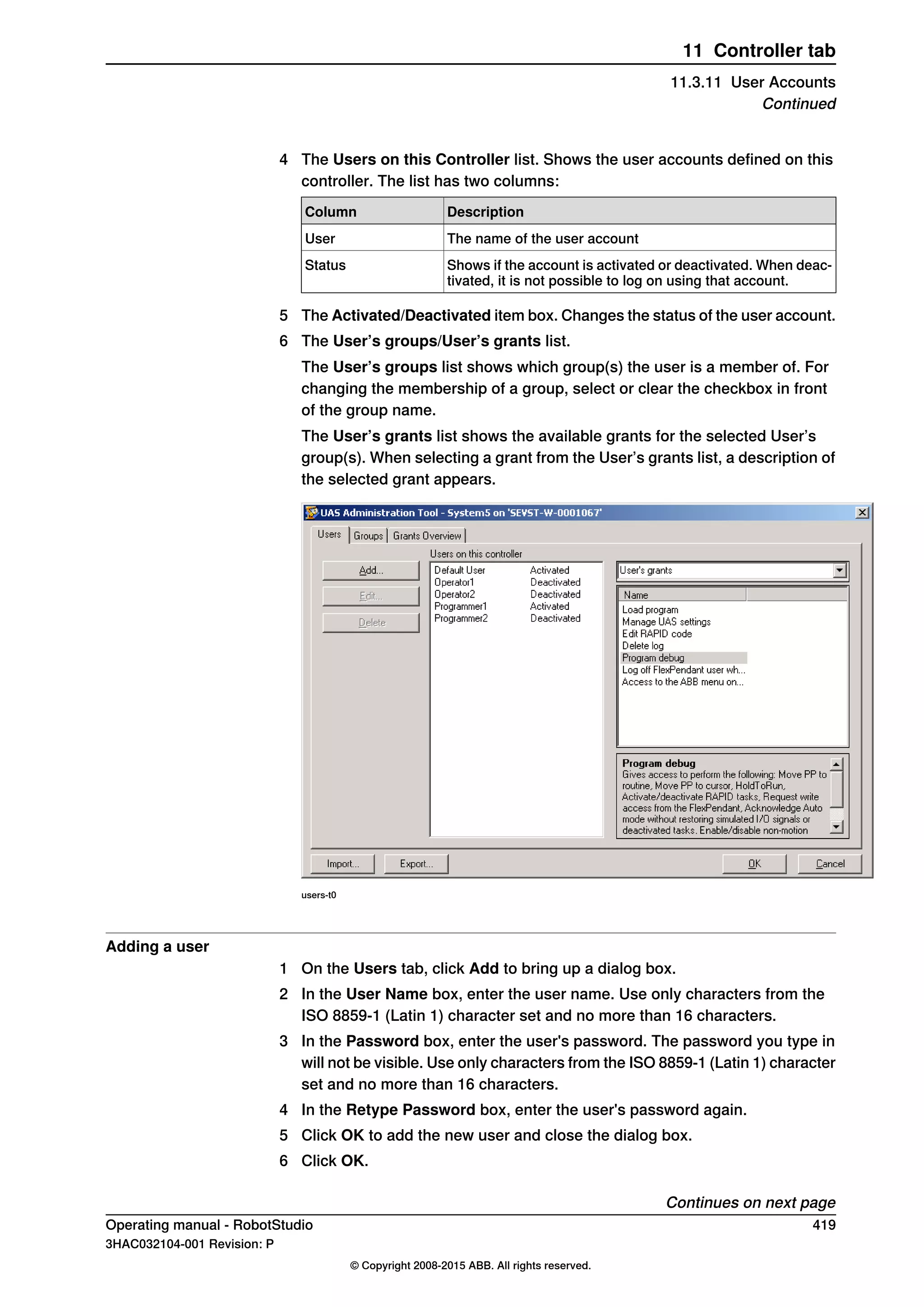
are numbered from zero for positive (counterclockwise) rotation and from -1 for
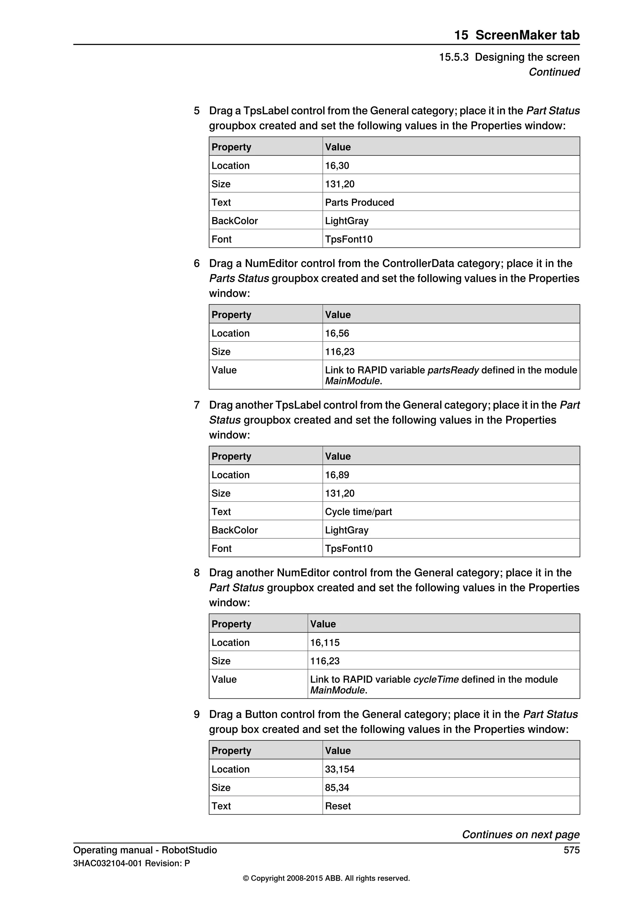
negative (clockwise) rotation.
For a linear axis, the integer specifies the range (in meters) from the neutral position
in which the axis is located.
A configuration for a six-axis industrial robot (like IRB 140) may look like:
[0-121]
The first integer (0) specifies the position of axis 1: somewhere in the first positive
quadrant (between 0 and 90 degrees rotation).
The second integer (-1) specifies the position of axis 4: somewhere in the first
negative quadrant (between 0 and -90 degrees rotation).
The third integer (2) specifies the position of axis 6: somewhere in the third positive
quadrant (between 180 and 270 degrees rotation).
The fourth integer (1) specifies the position of axis x, a virtual axis used for
specifying the wrist center in relation to other axes.
Configuration monitoring
When executing a robot program, you can choose whether to monitor configuration
values. If configuration monitoring is turned off, configuration values stored with
the targets are ignored, and the robot will use the configuration closest its current
configuration for reaching the target. If turned on, it will only use the specified
configuration for reaching the targets.
Configuration monitoring can be turned off and on for joint and linear movements
independently and is controlled by the ConfJ and ConfL action instructions.
Turning configuration monitoring off
Running a program without configuration monitoring may result in different
configurations each time a cycle is executed: When the robot returns to the start
position after completing a cycle, it may choose a different configuration then the
original.
For programs with linear move instructions this might cause a situation where the
robot gets closer and closer its joint limits and eventually will not be able to reach
the target.
For programs with joint move instructions this might cause sweeping, unpredictable
movements.
Turning configuration monitoring on
Running a program with configuration monitoring forces the robot to use the
configurations stored with the targets. This results in predictable cycles and
predictable motions. In some situations, however, like when the robot moves to a
target from an unknown position, using configuration monitoring may limit the
robot’s reachability.
When programming offline, you must assign a configuration to each target if the
program shall be executed with configuration monitoring.
38 Operating manual - RobotStudio
3HAC032104-001 Revision: P
© Copyright 2008-2015 ABB. All rights reserved.
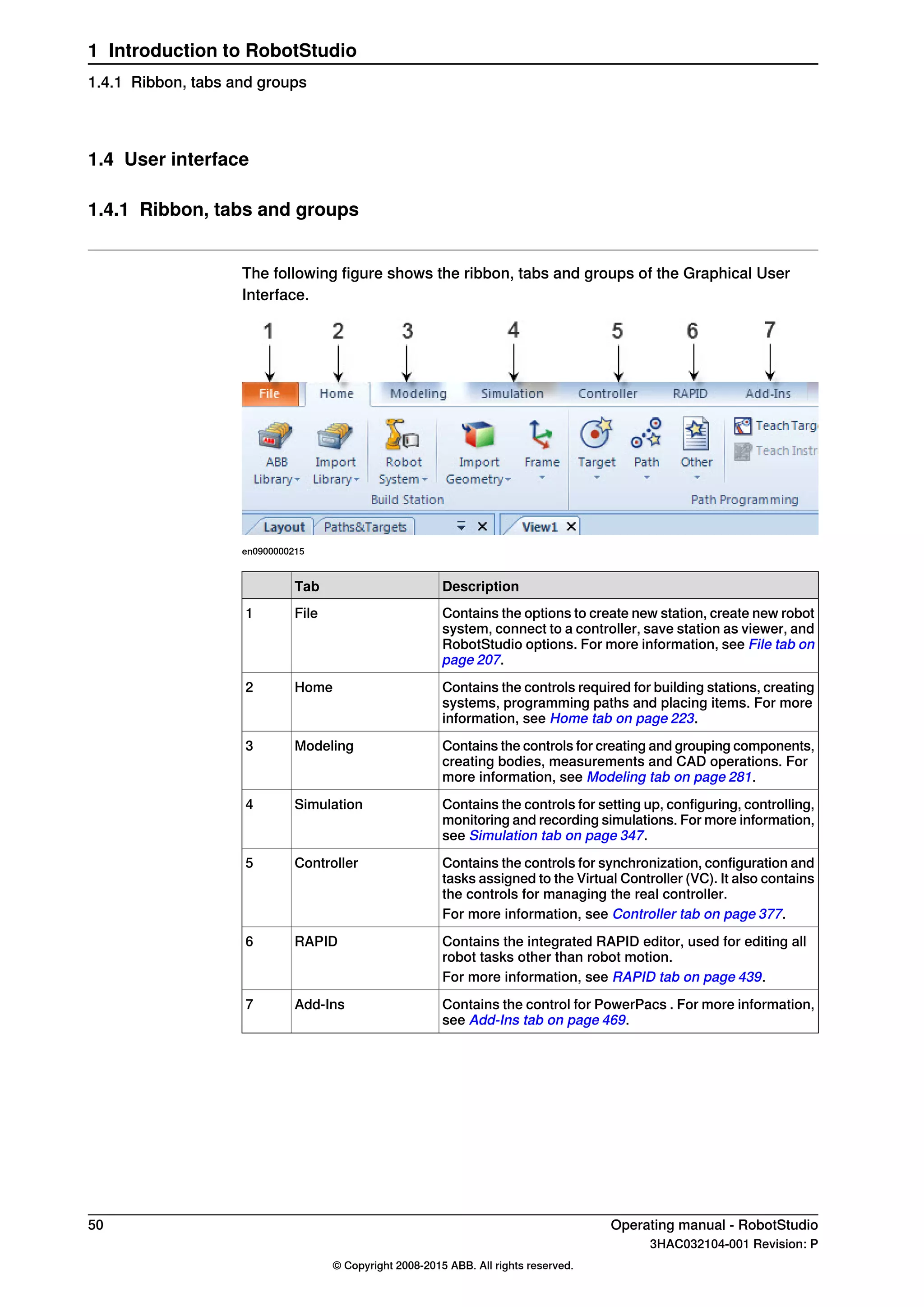
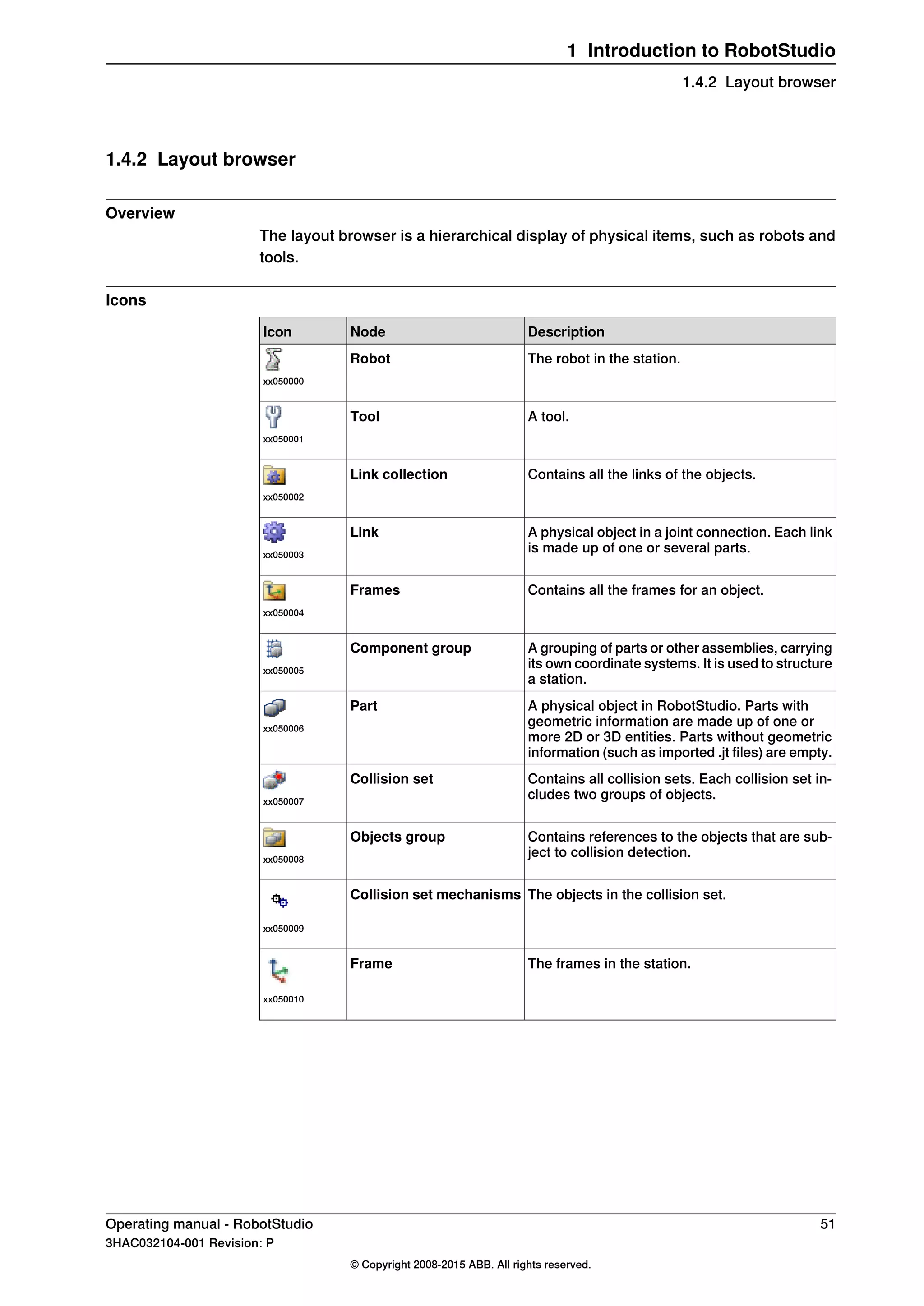
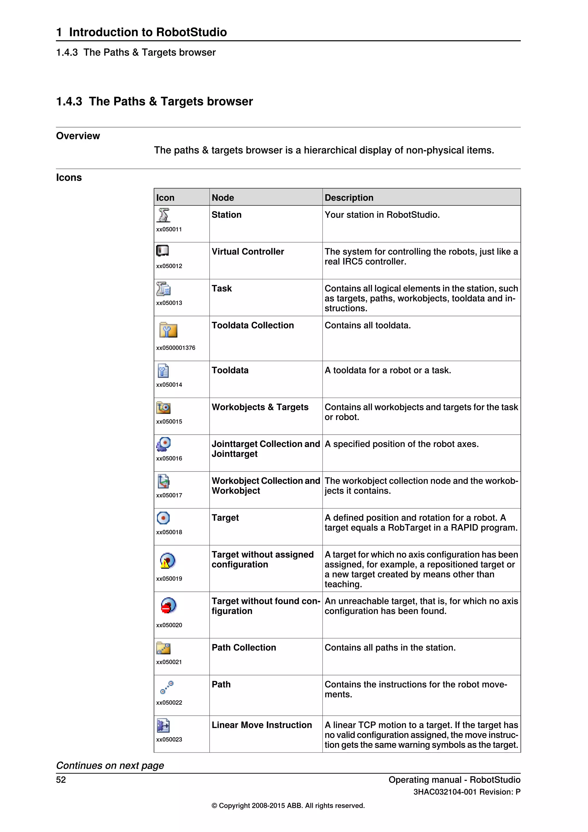
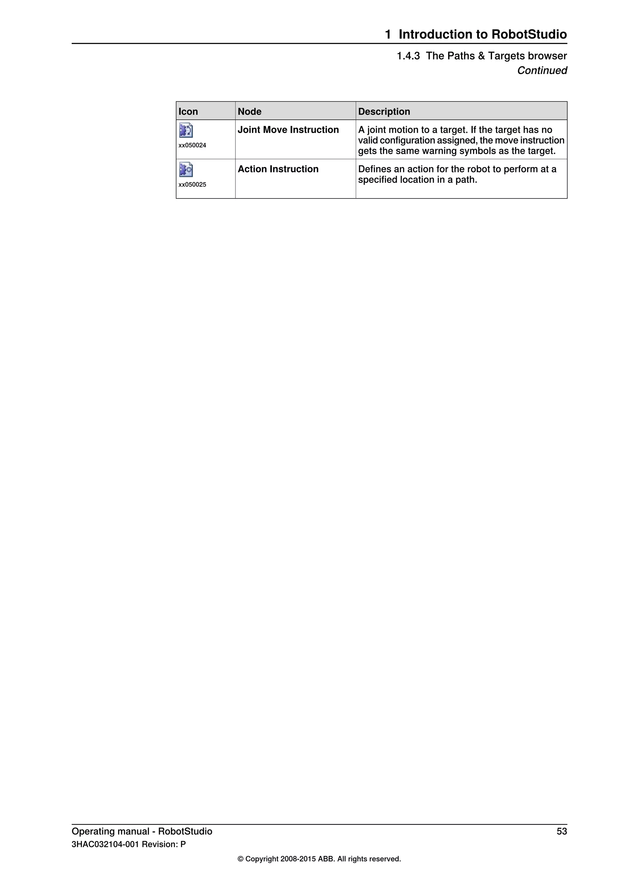
1 Introduction to RobotStudio
1.2.7 Robot axis configurations
Continued](https://image.slidesharecdn.com/prog-150726124729-lva1-app6892/75/Prog-38-2048.jpg)


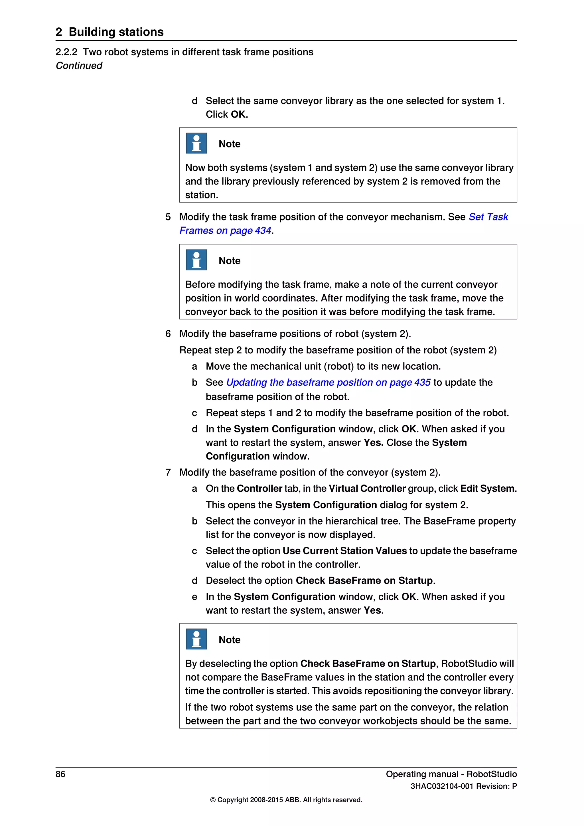


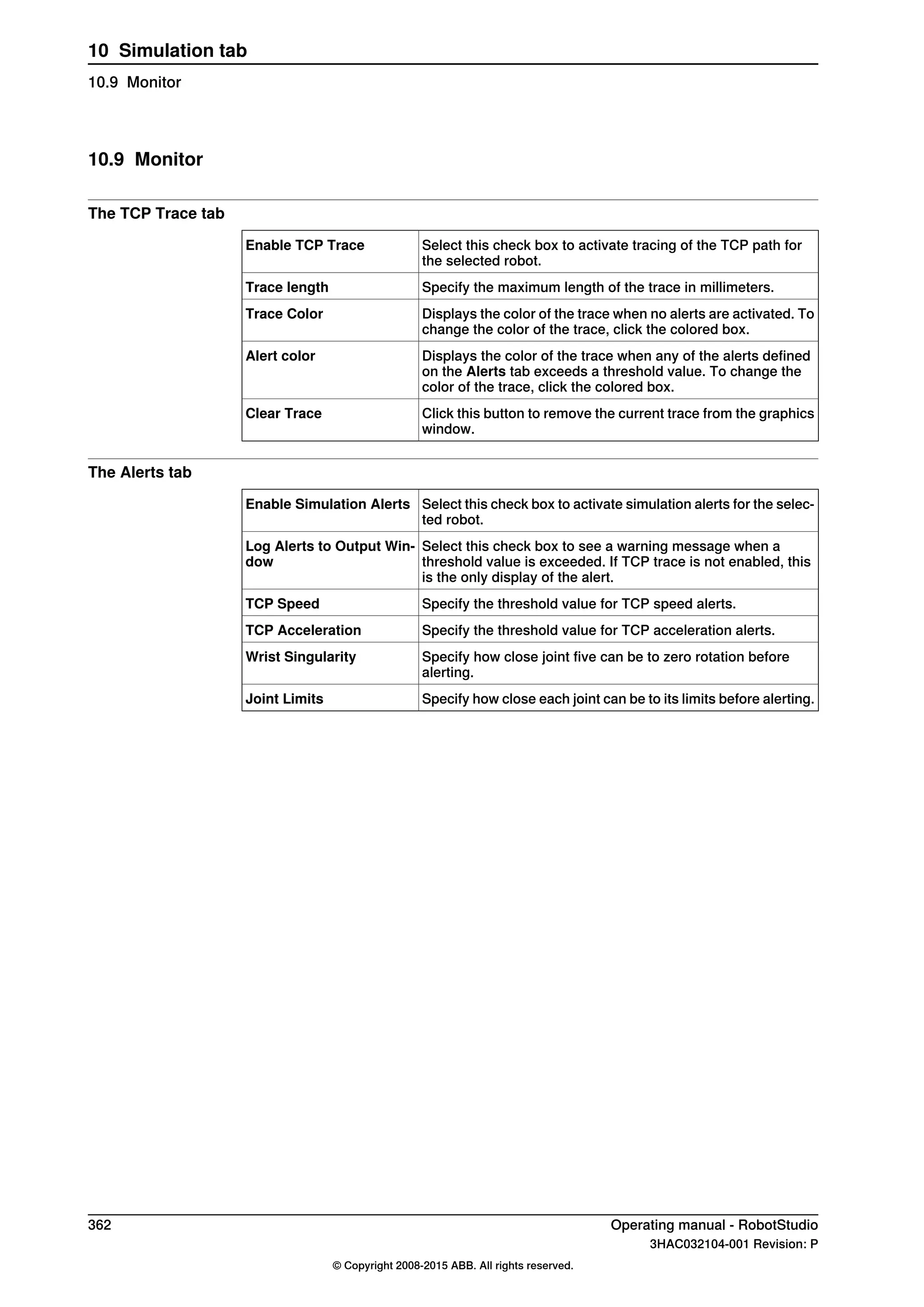
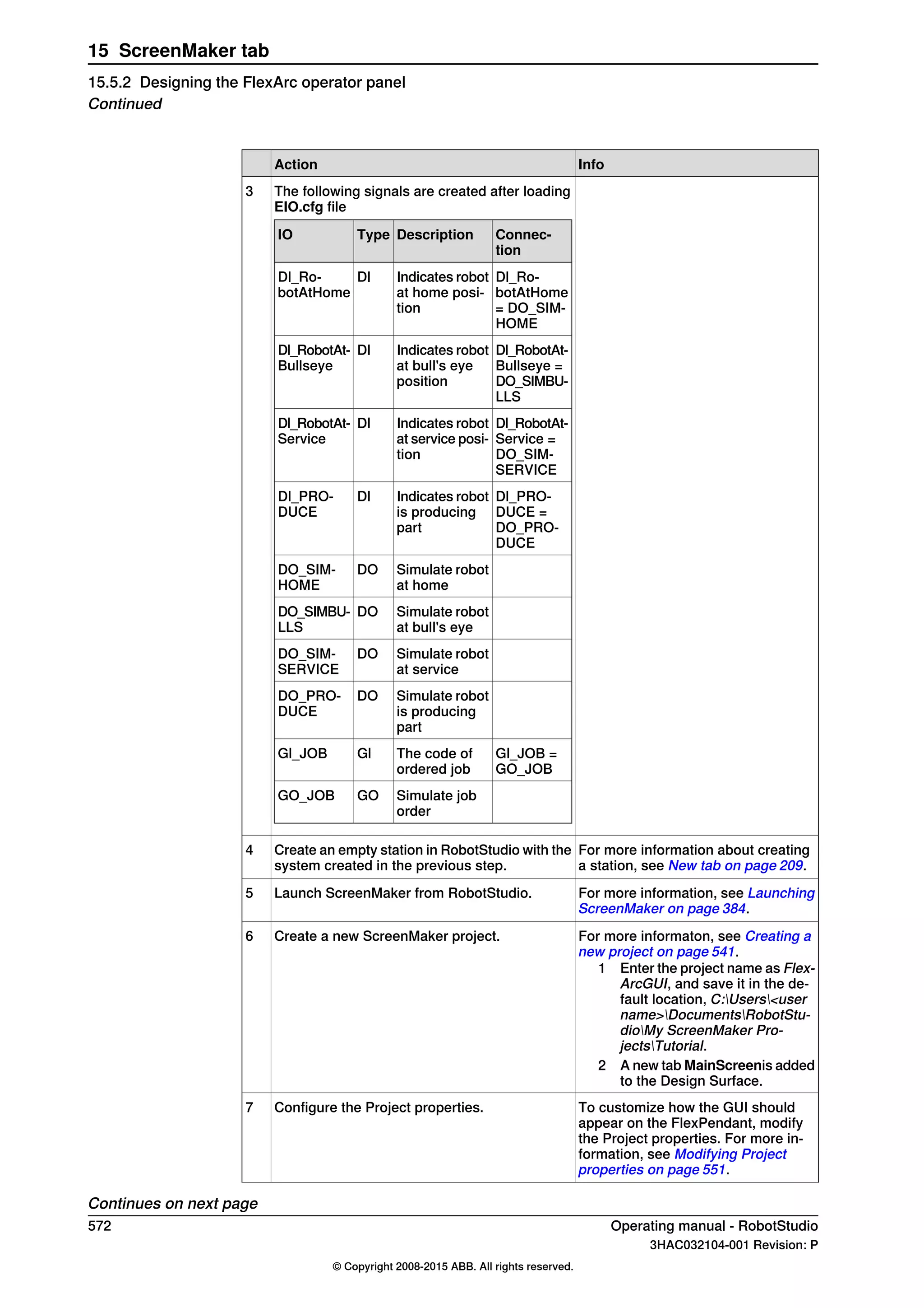
![9.4 Smart Component
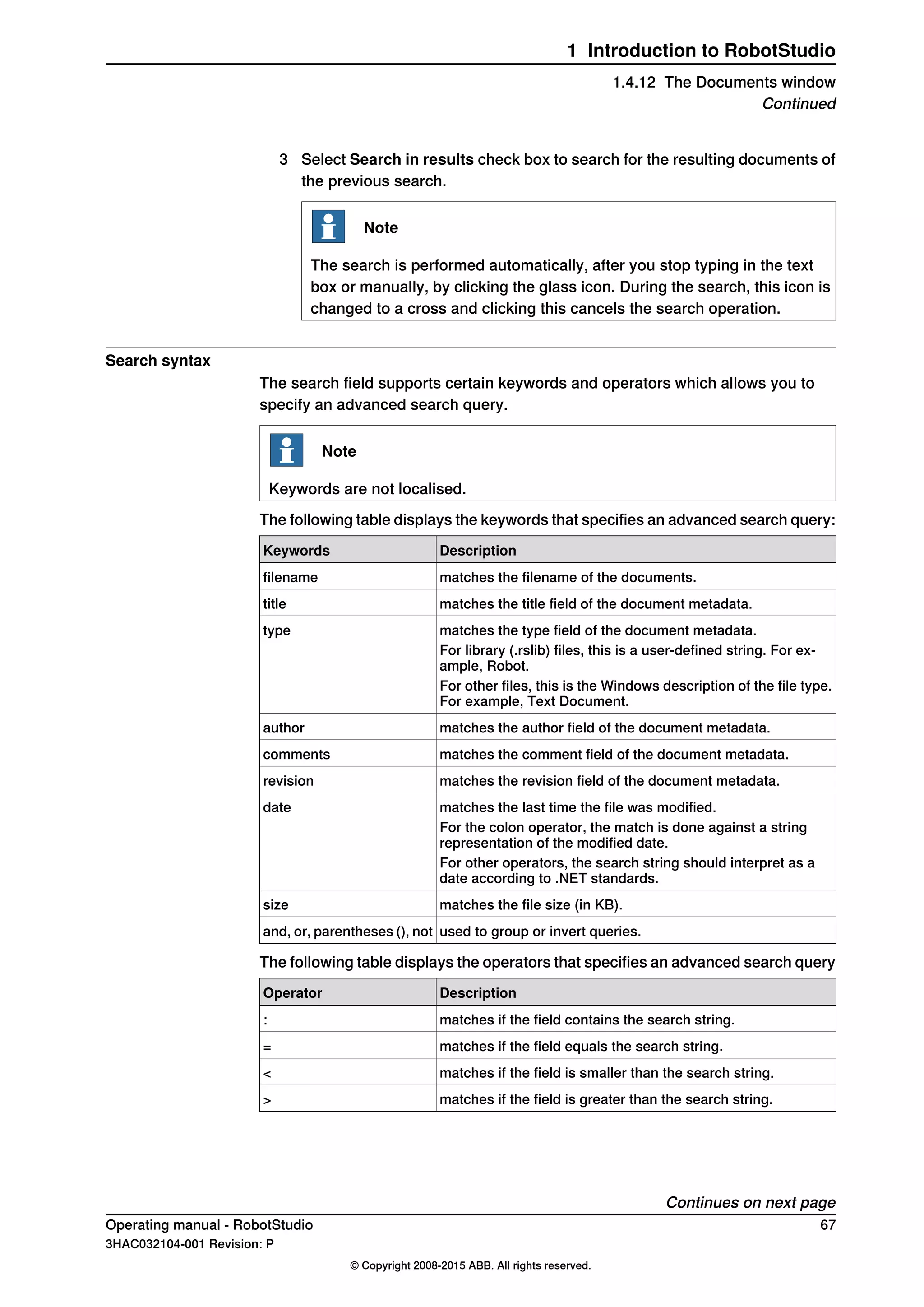
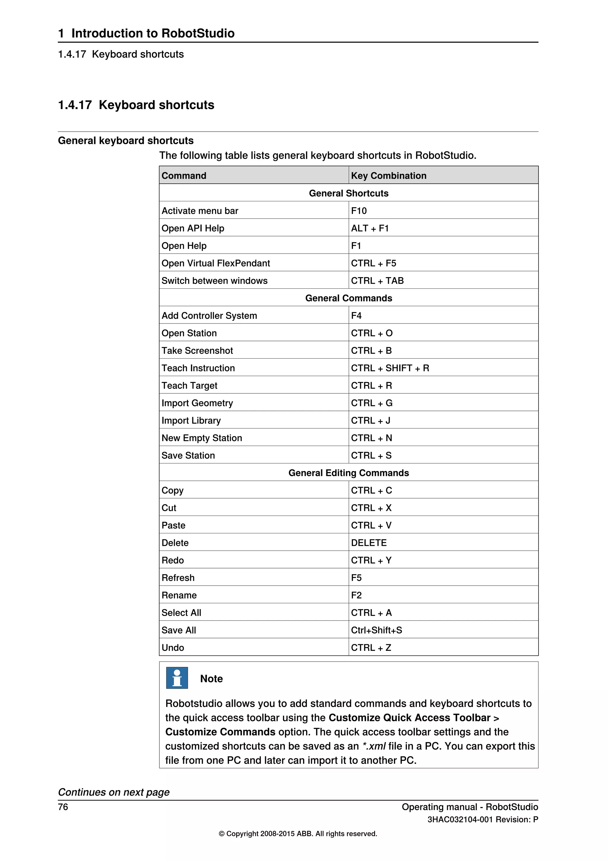
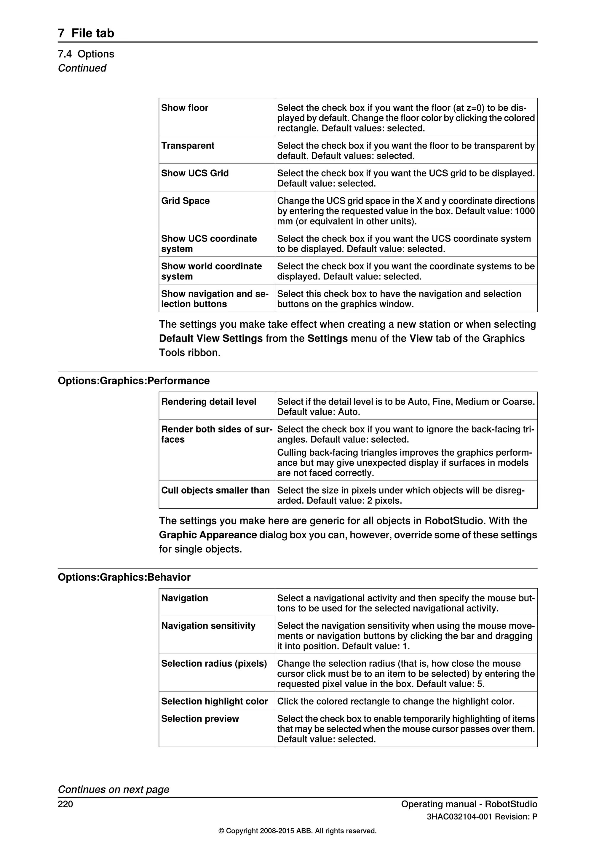
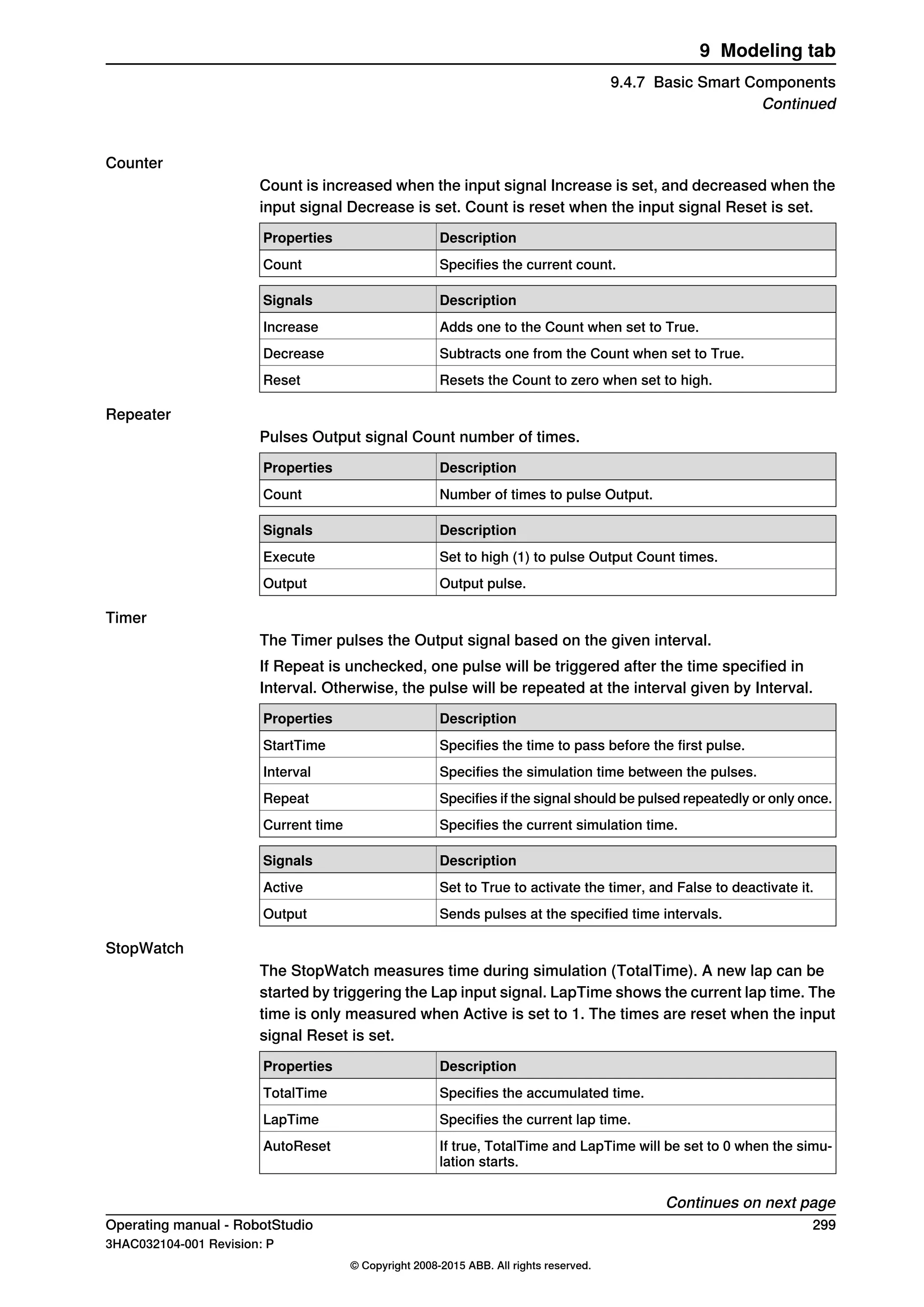
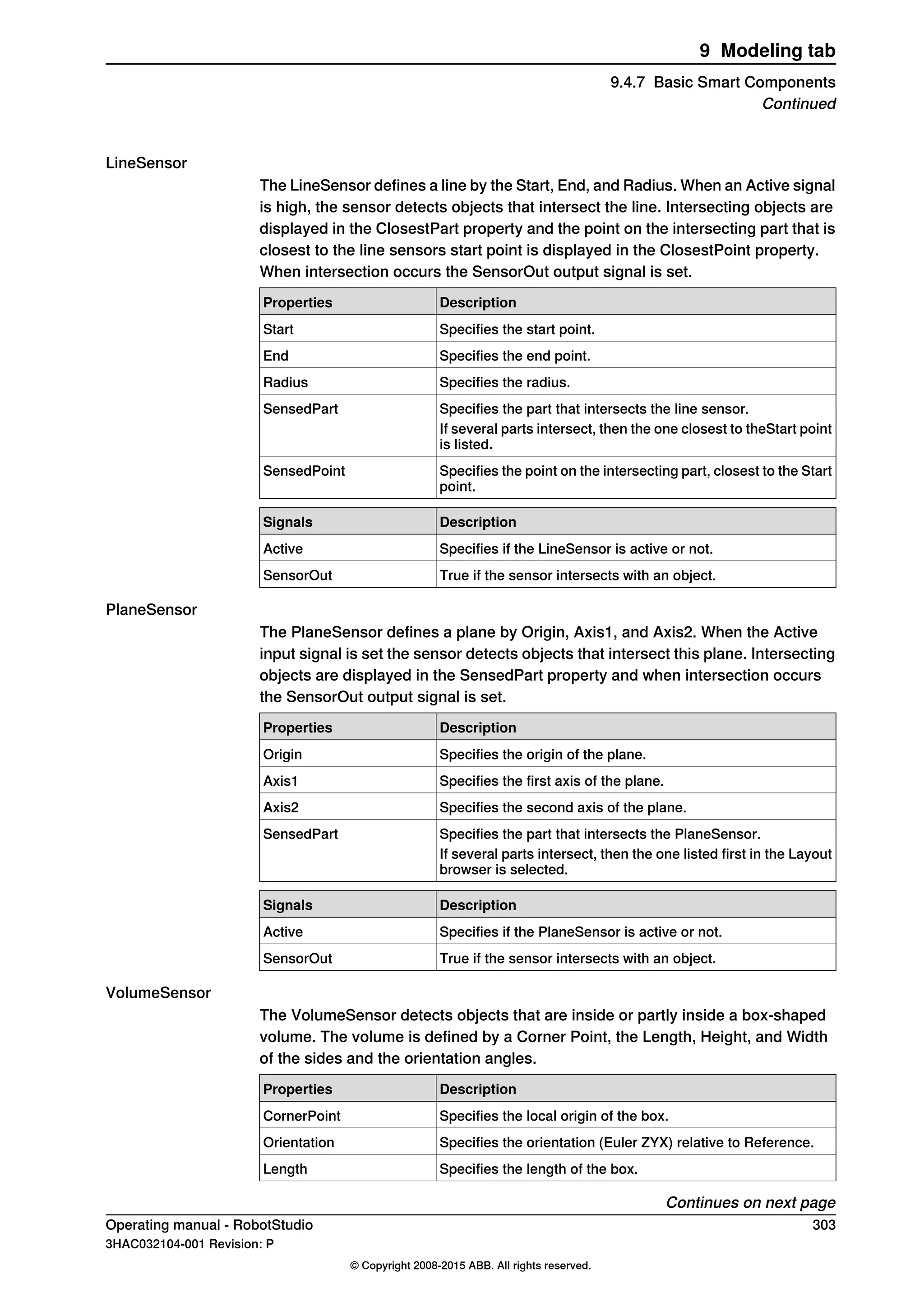
9.4.1 Smart Component
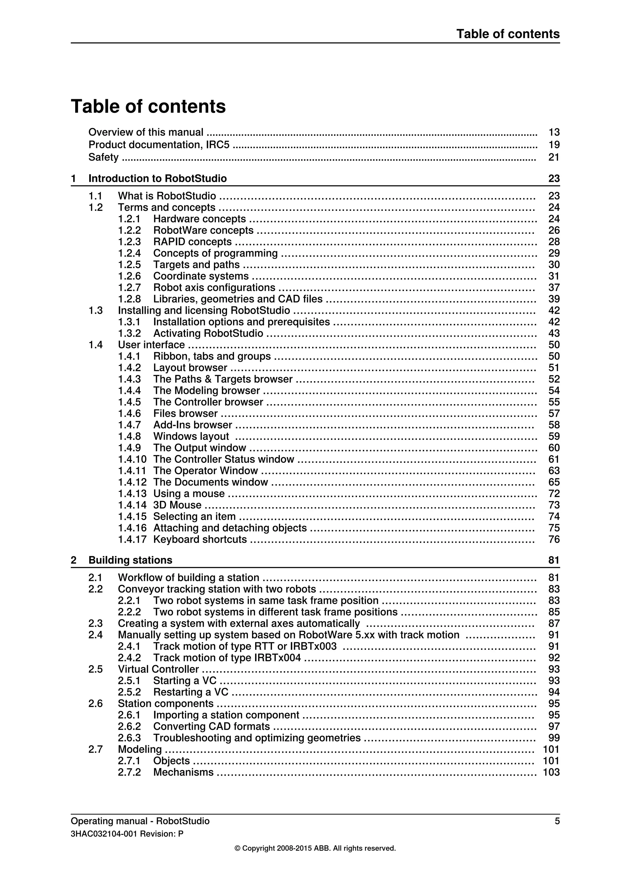
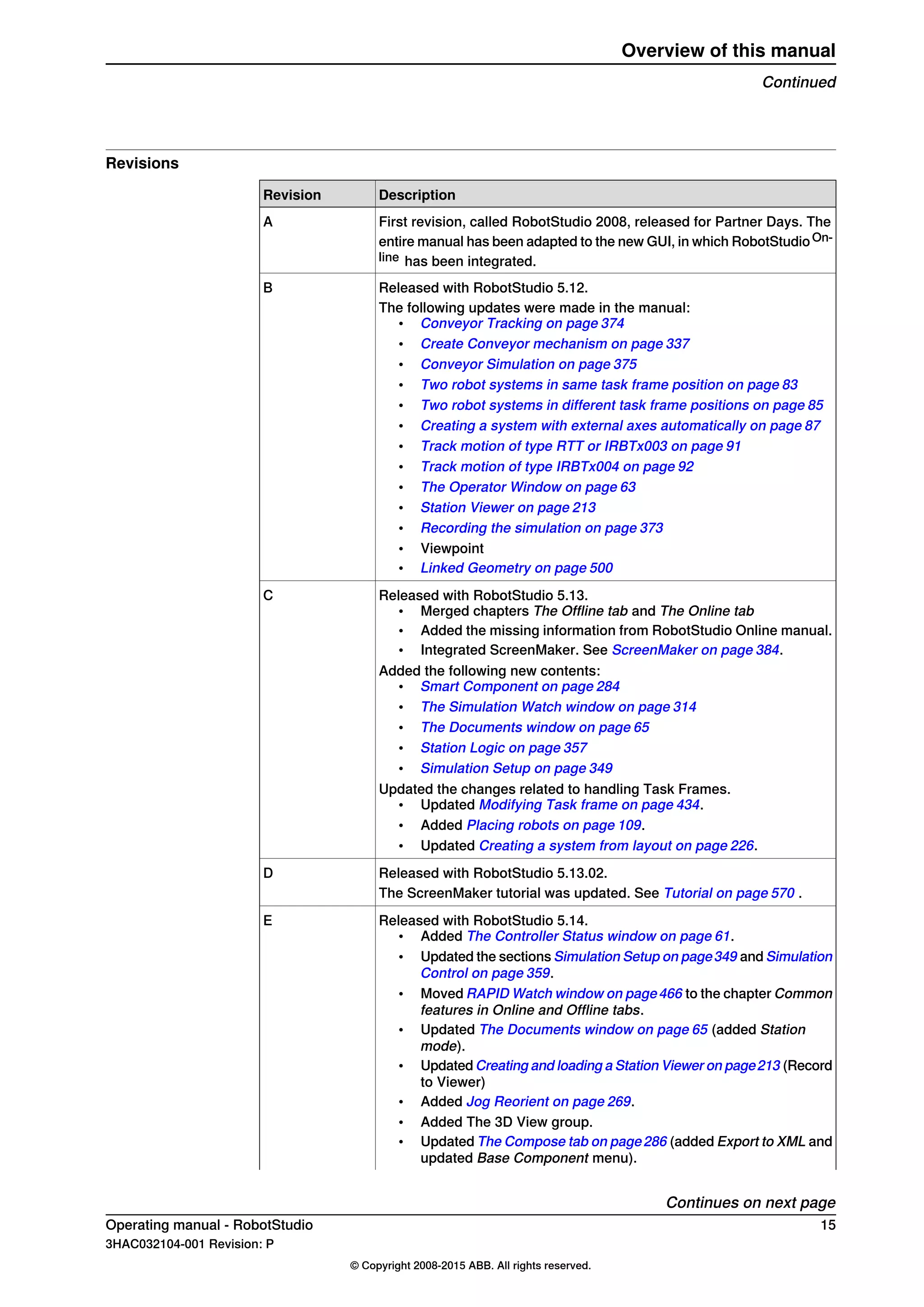
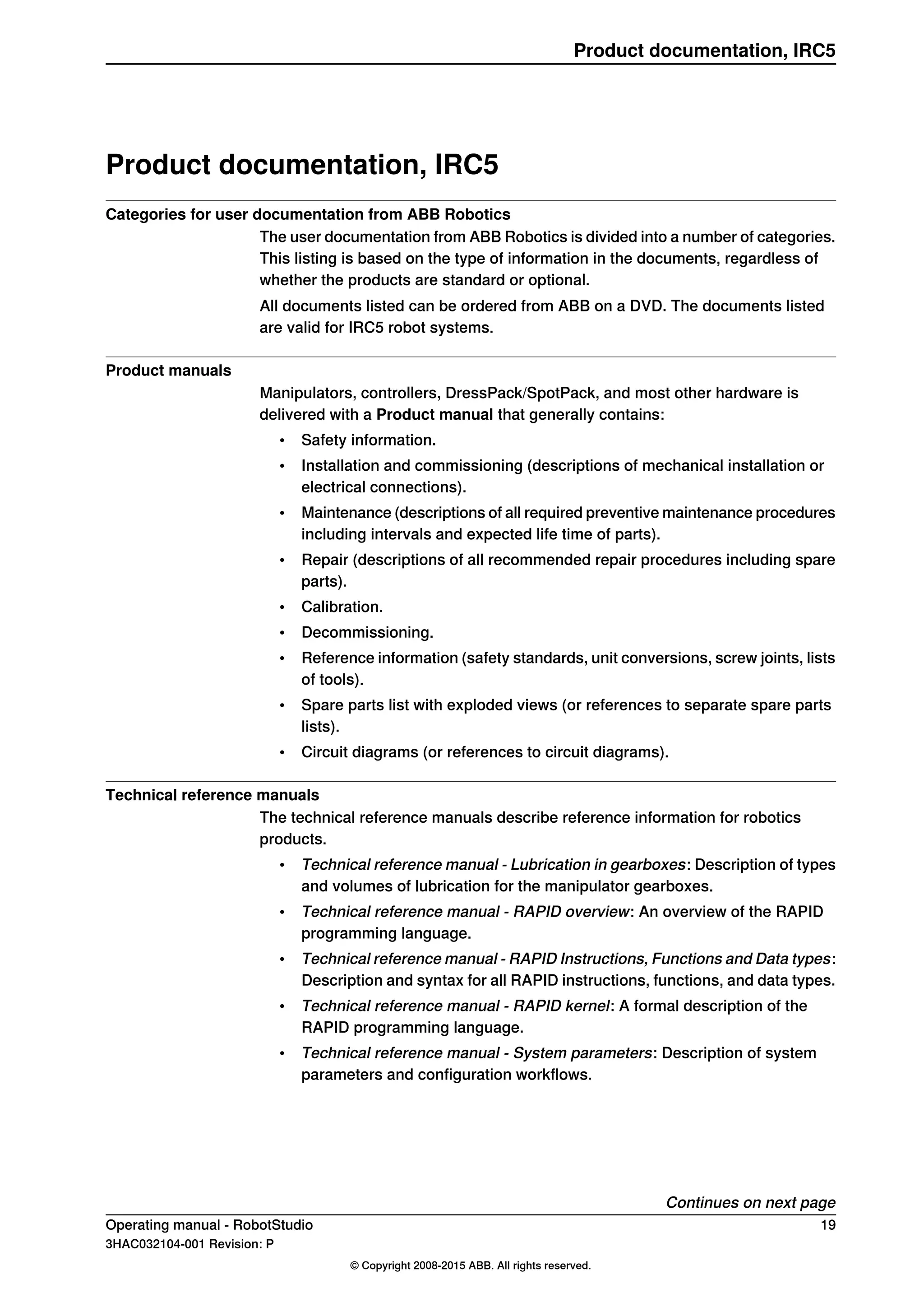
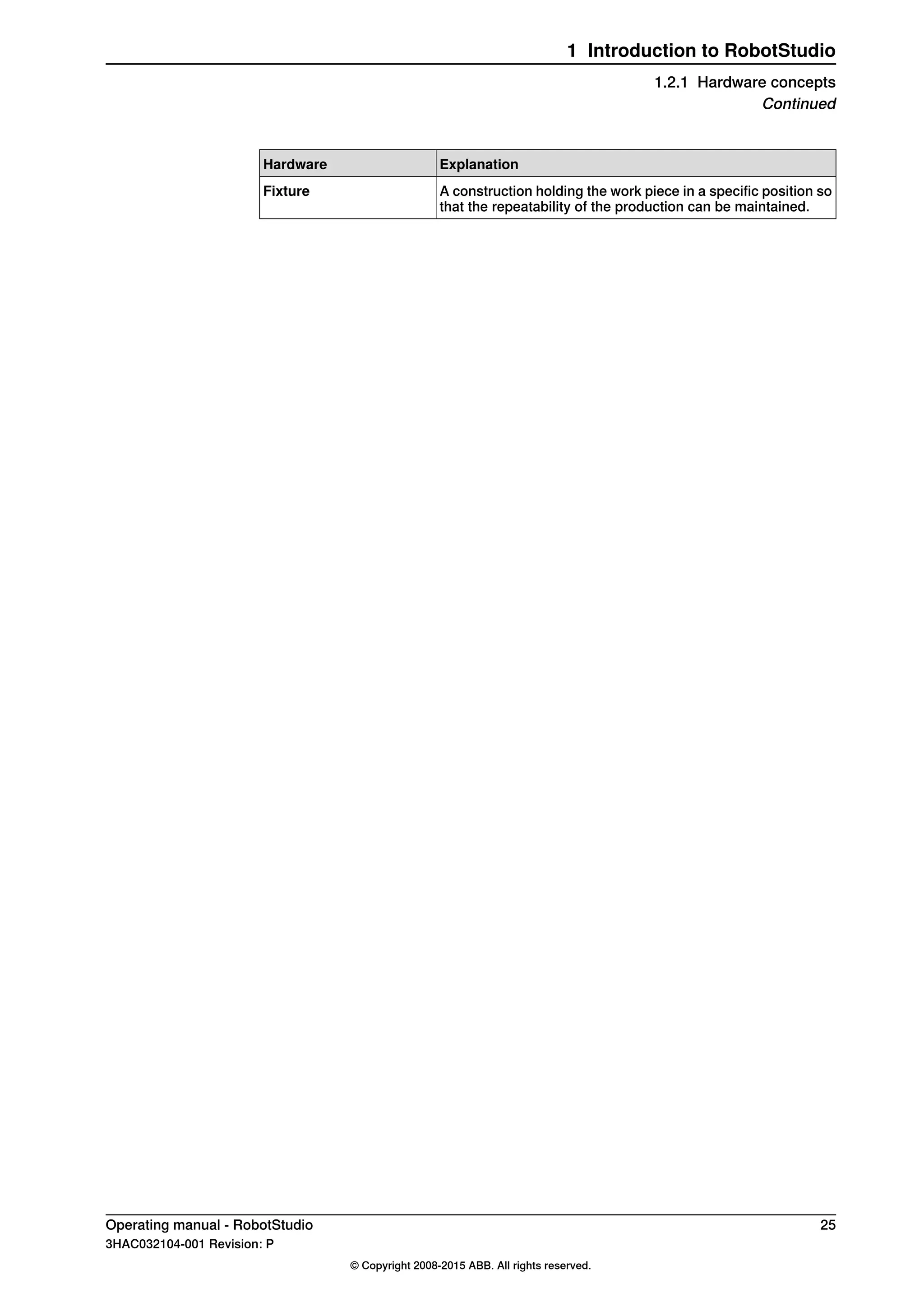
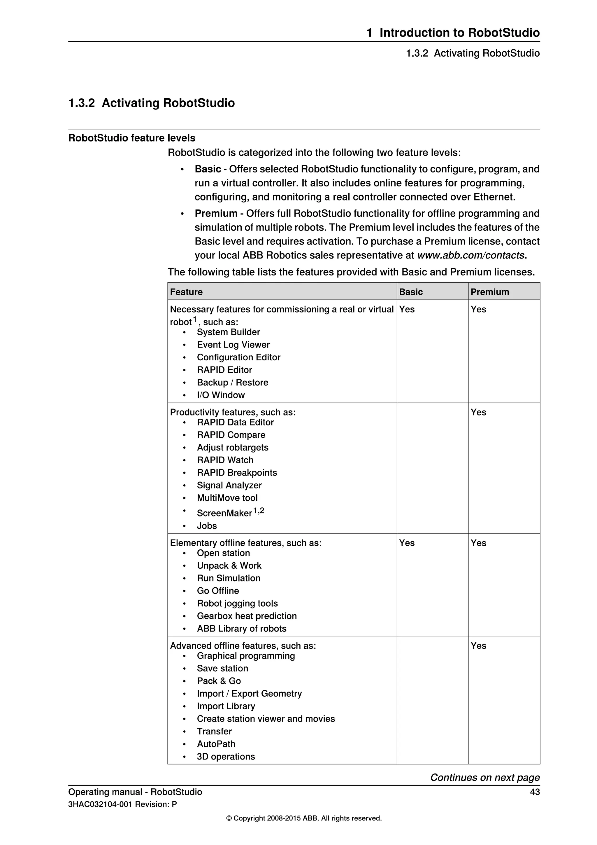
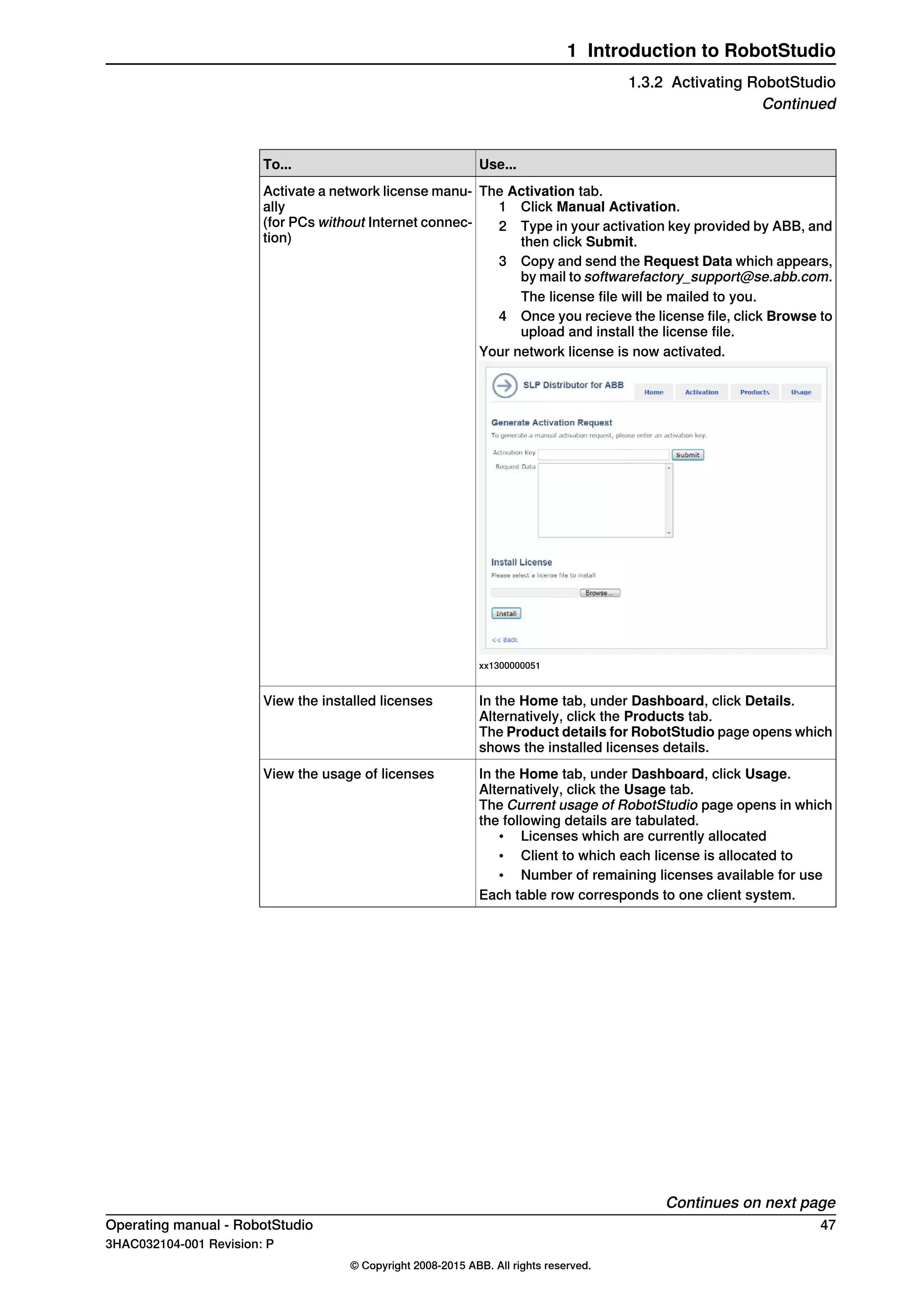
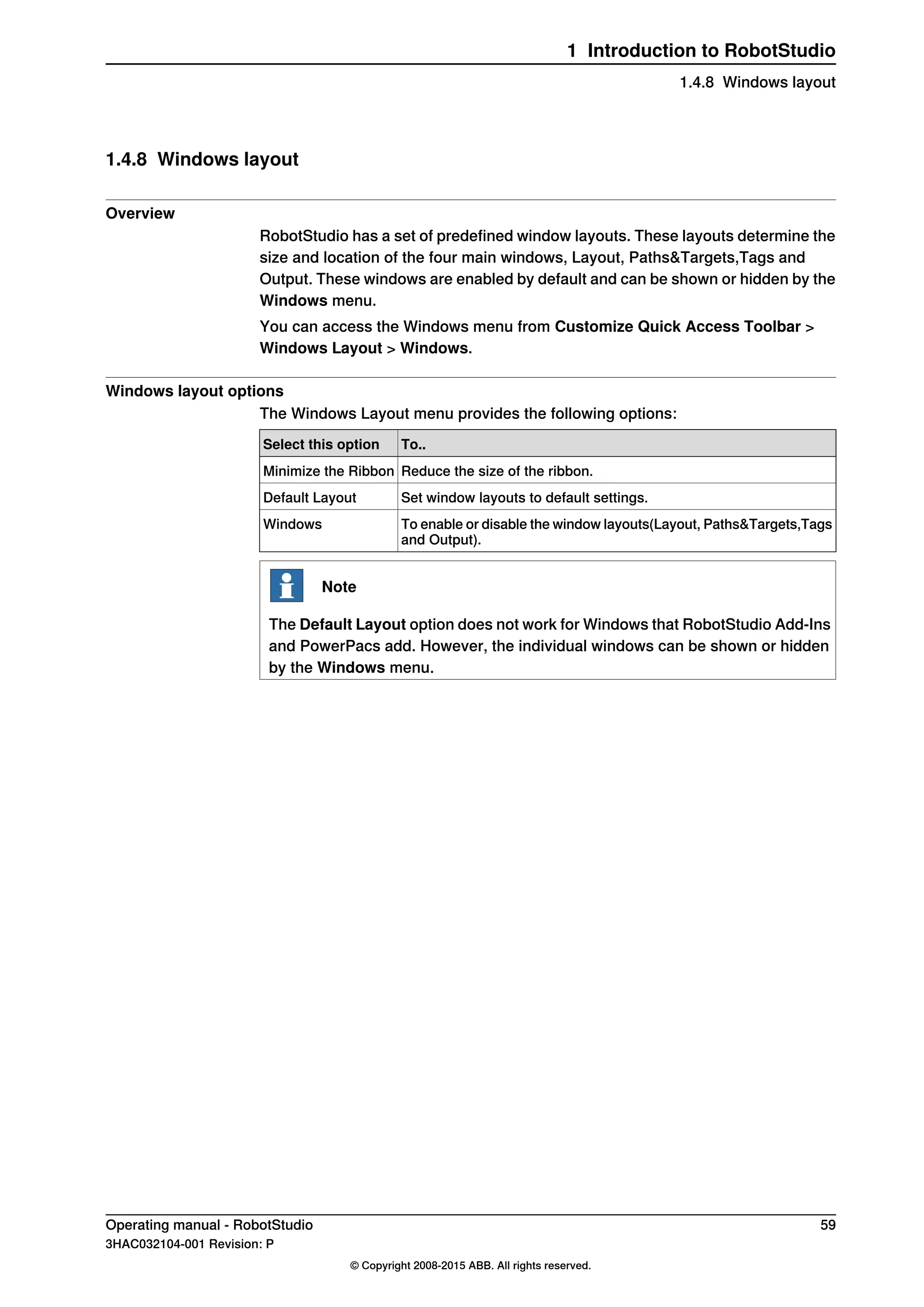
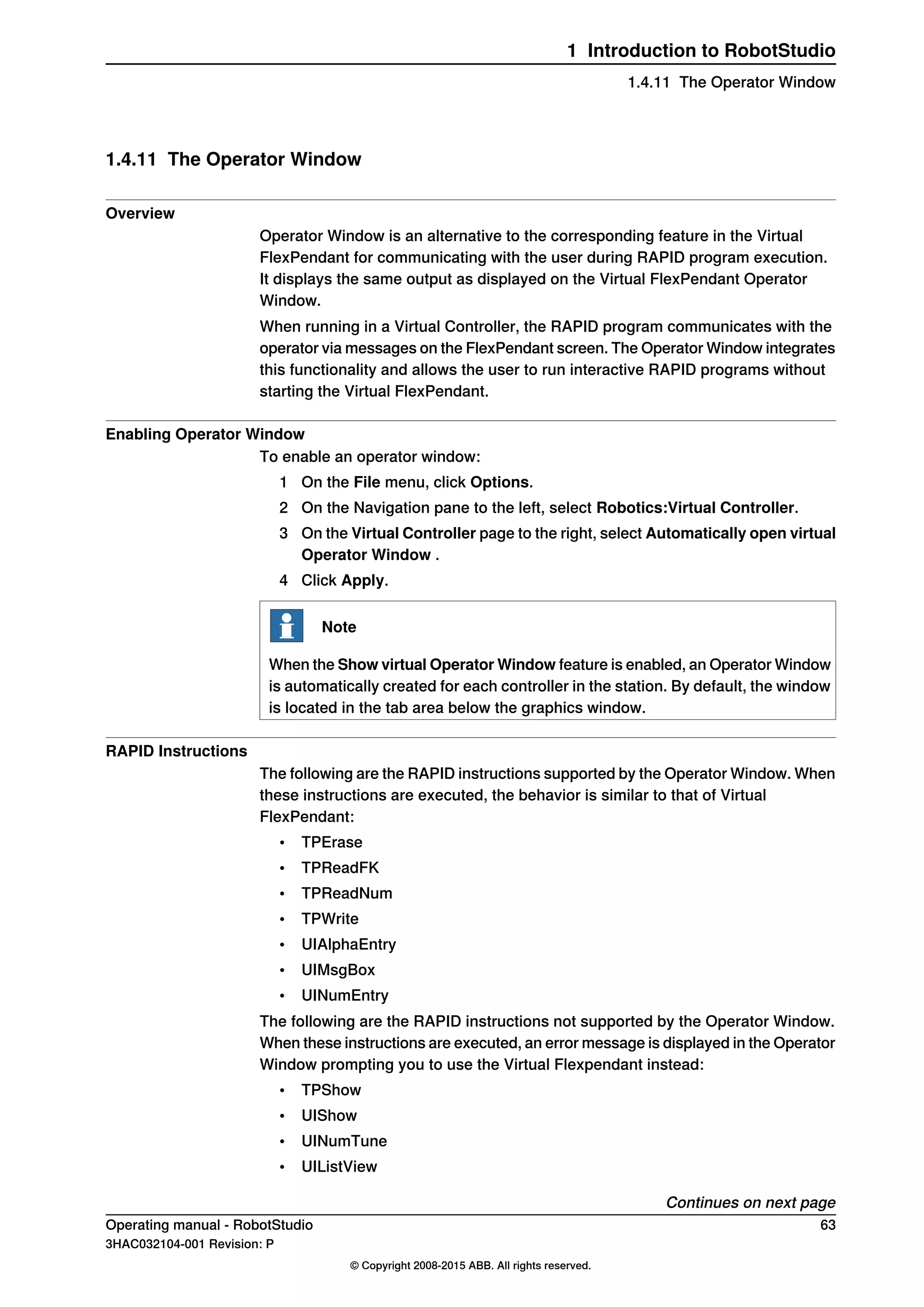
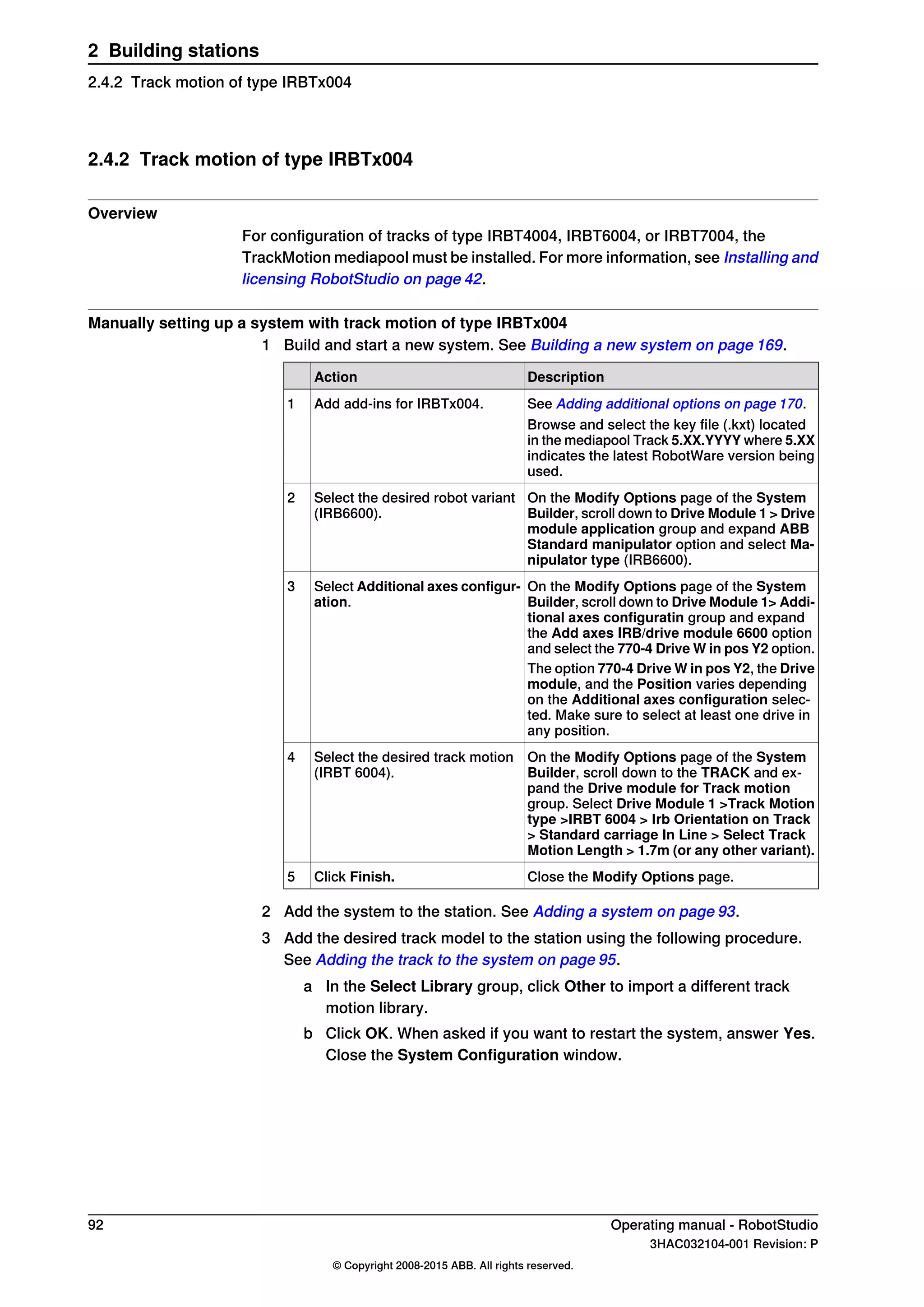
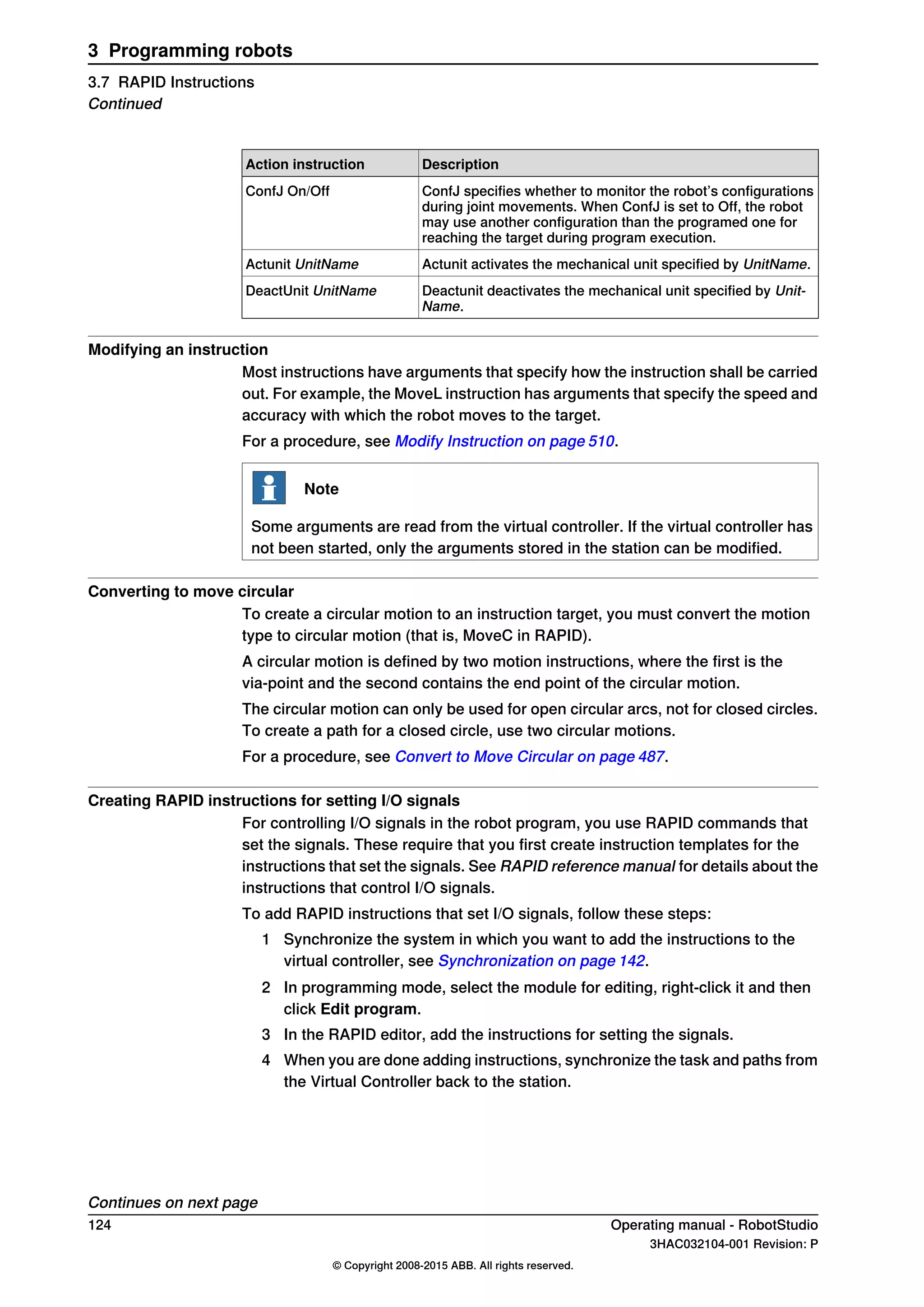
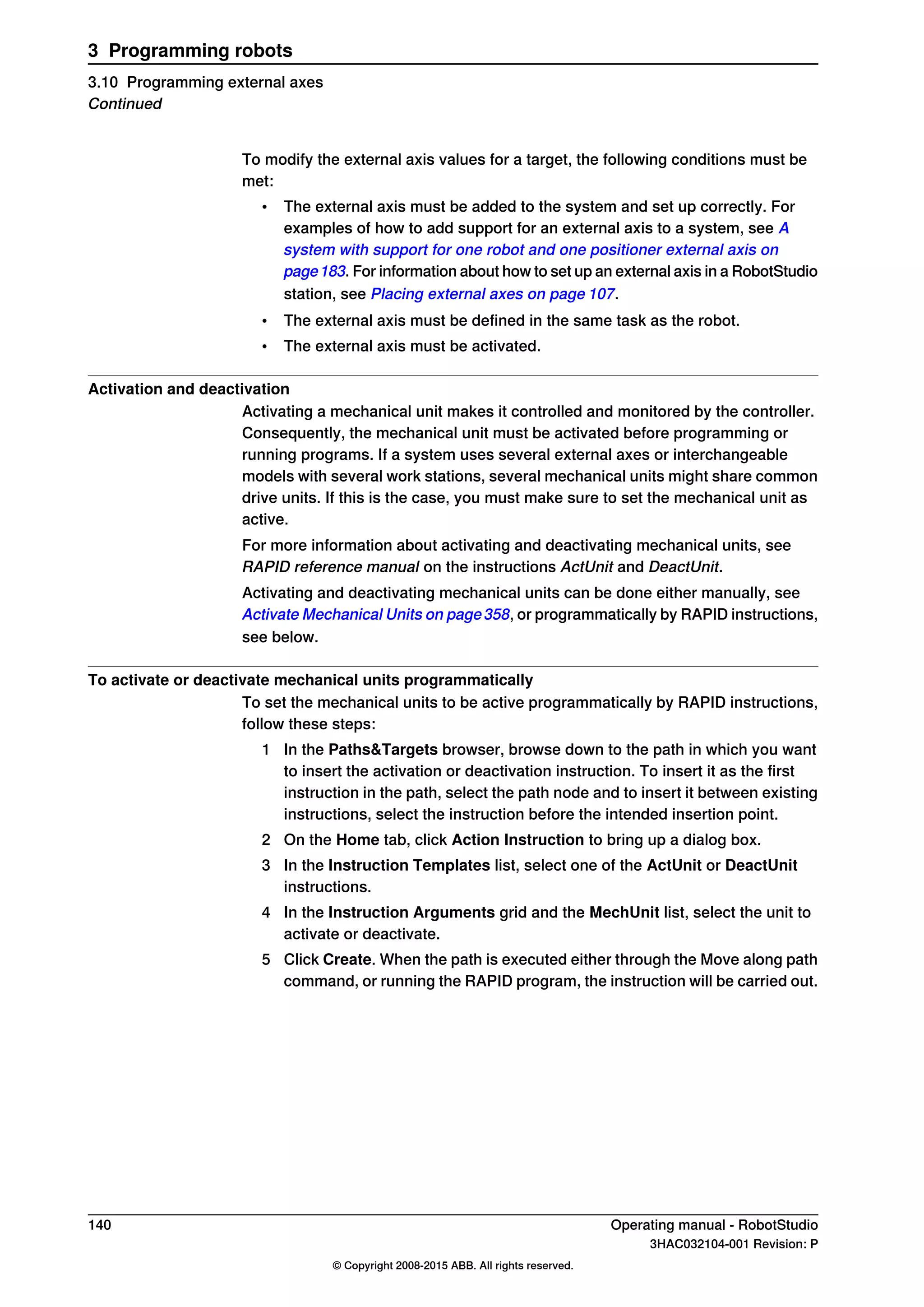
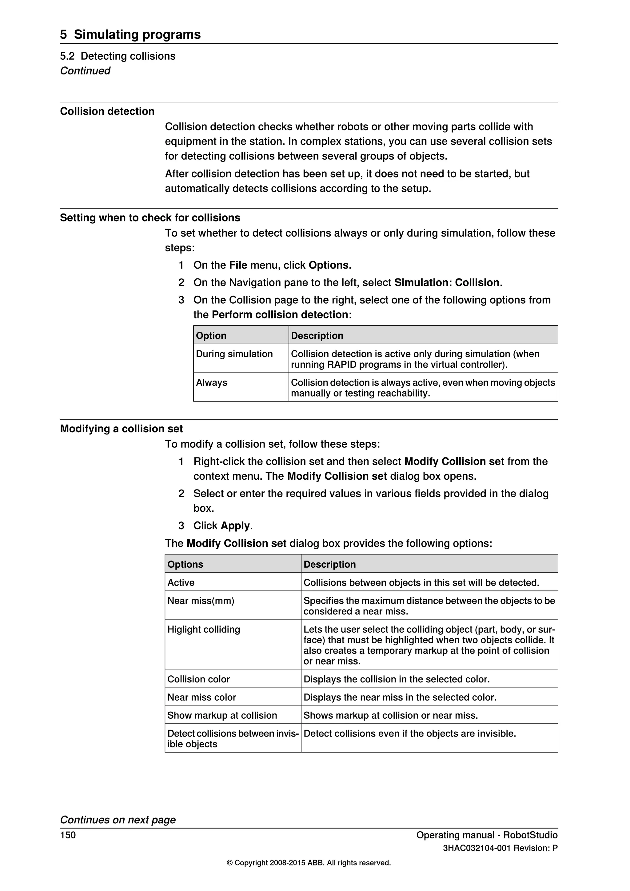
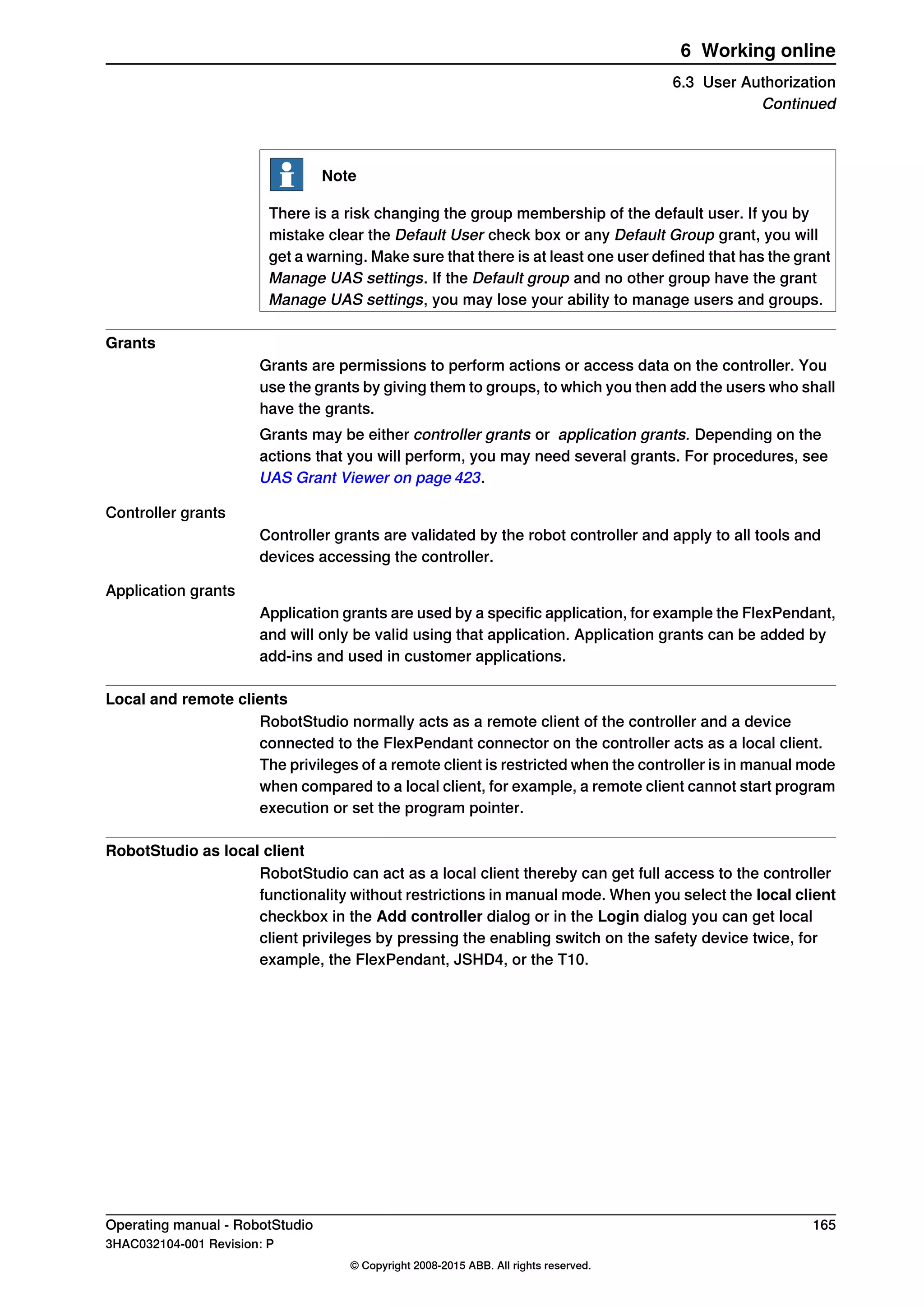
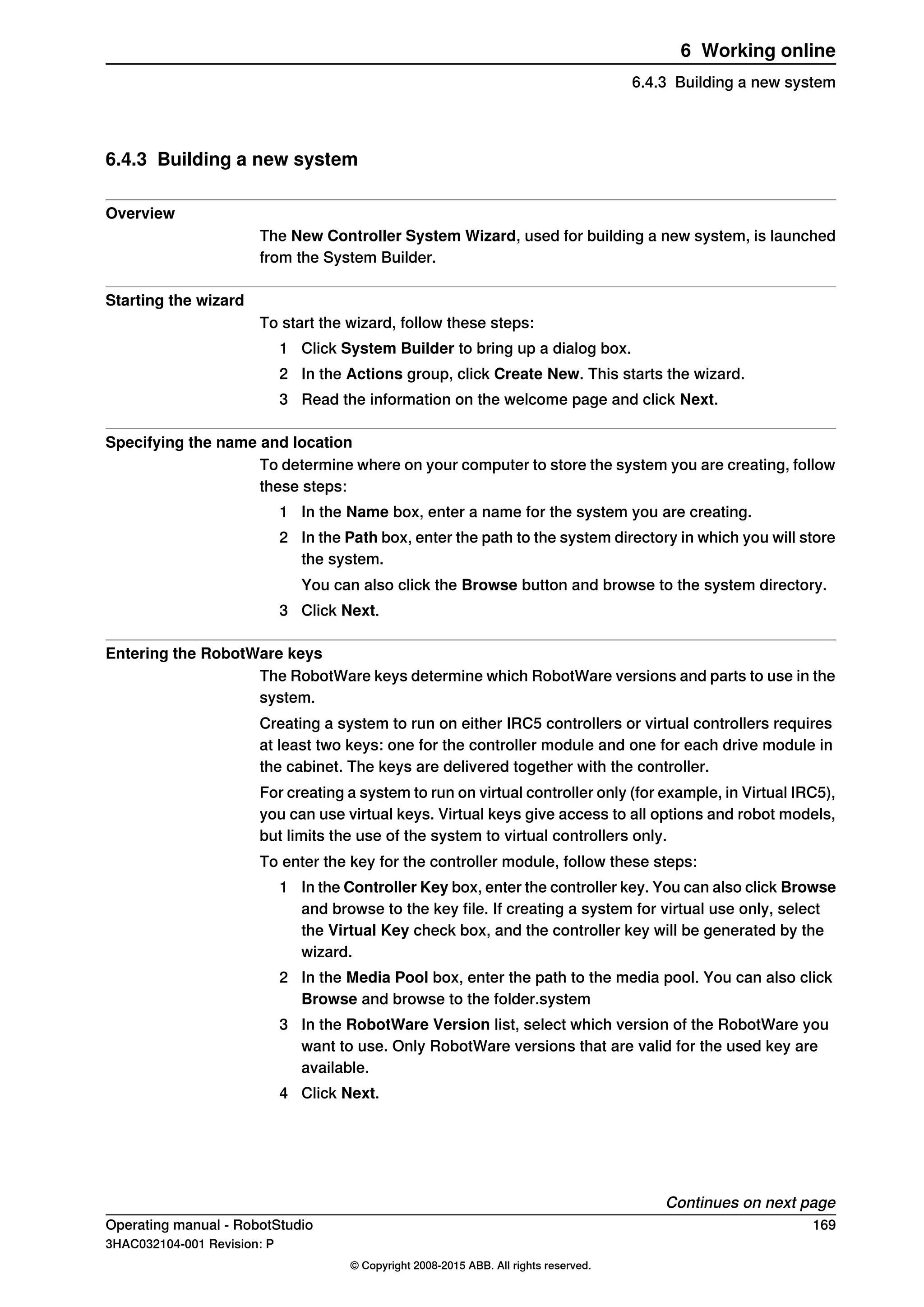
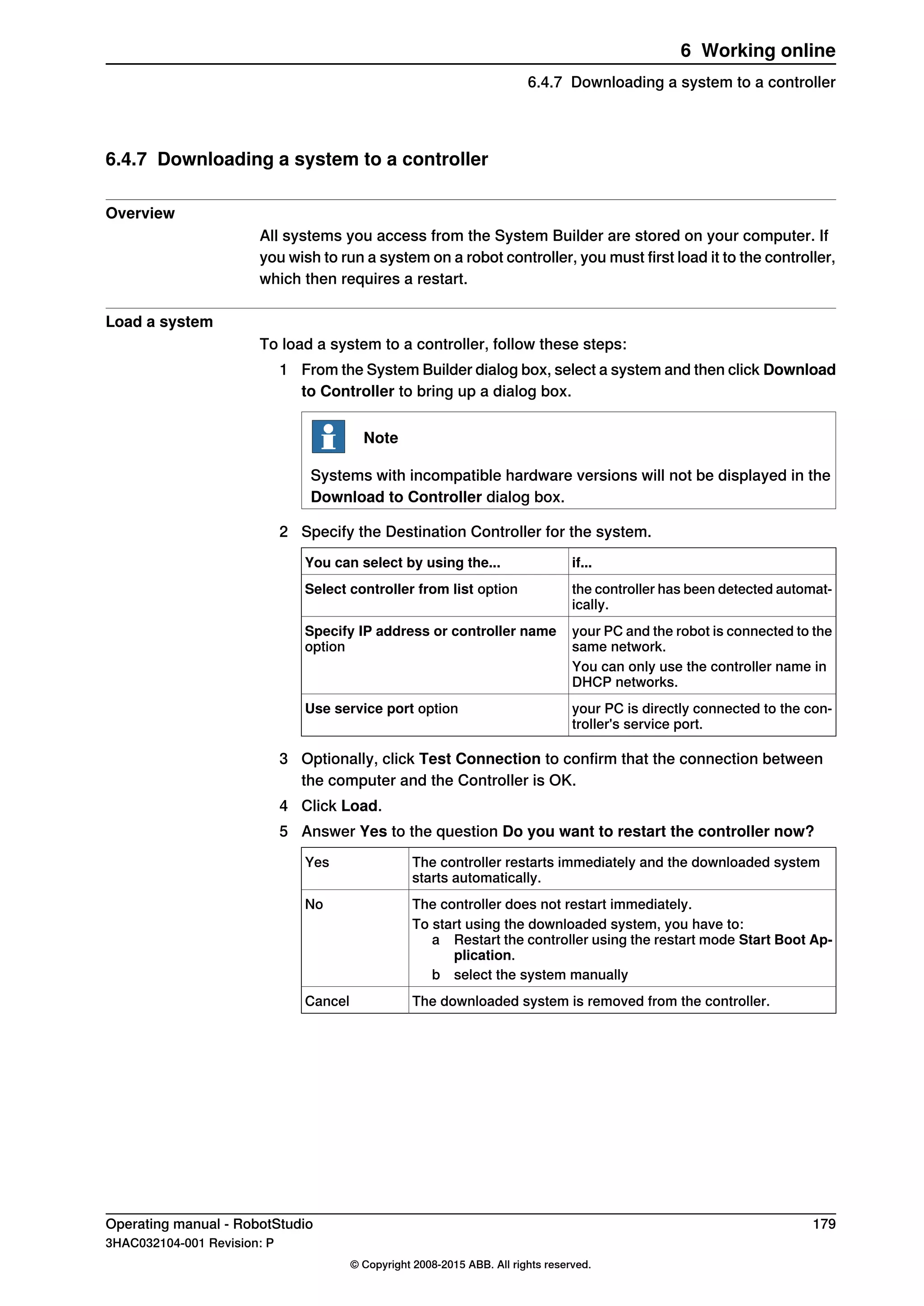
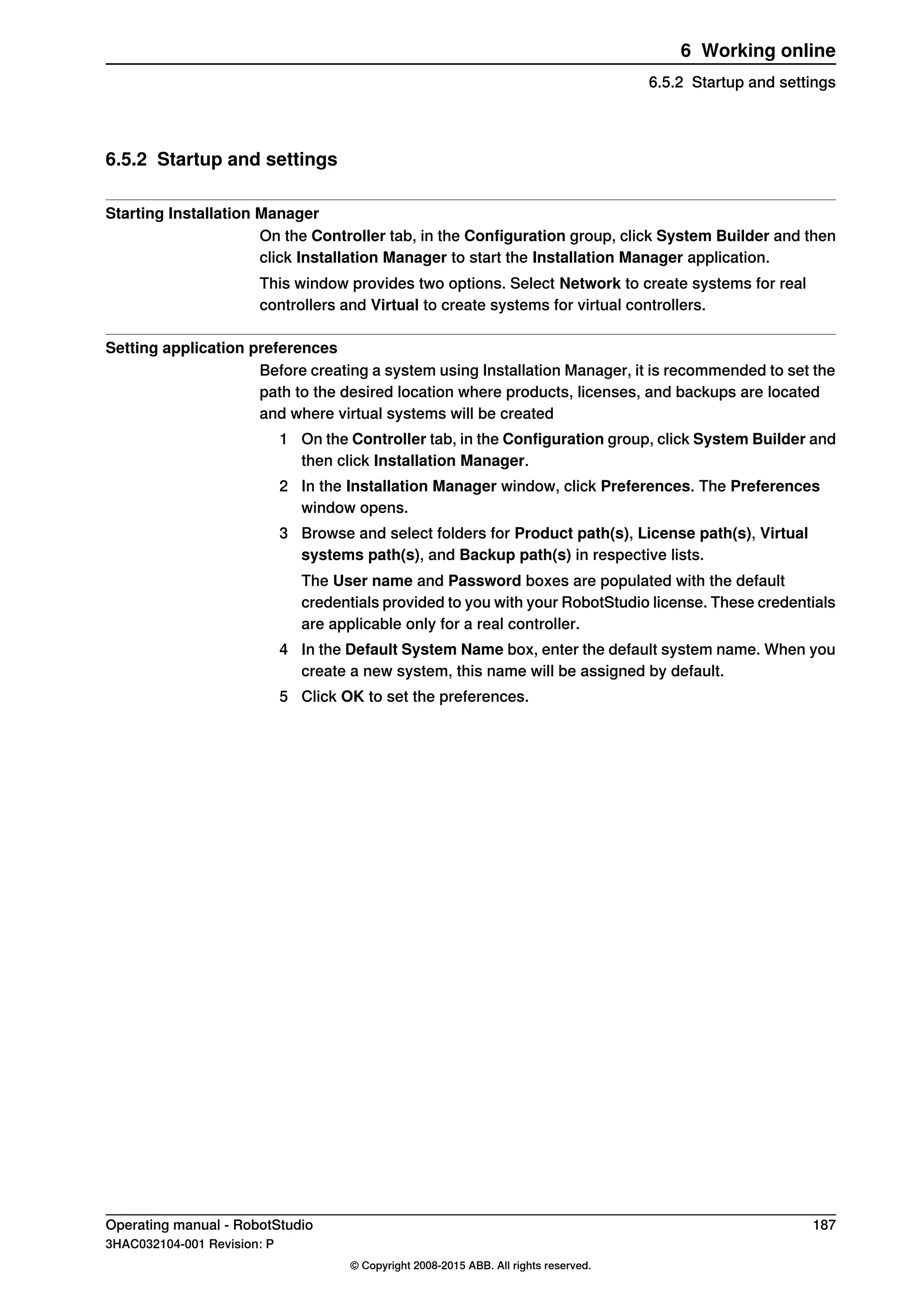
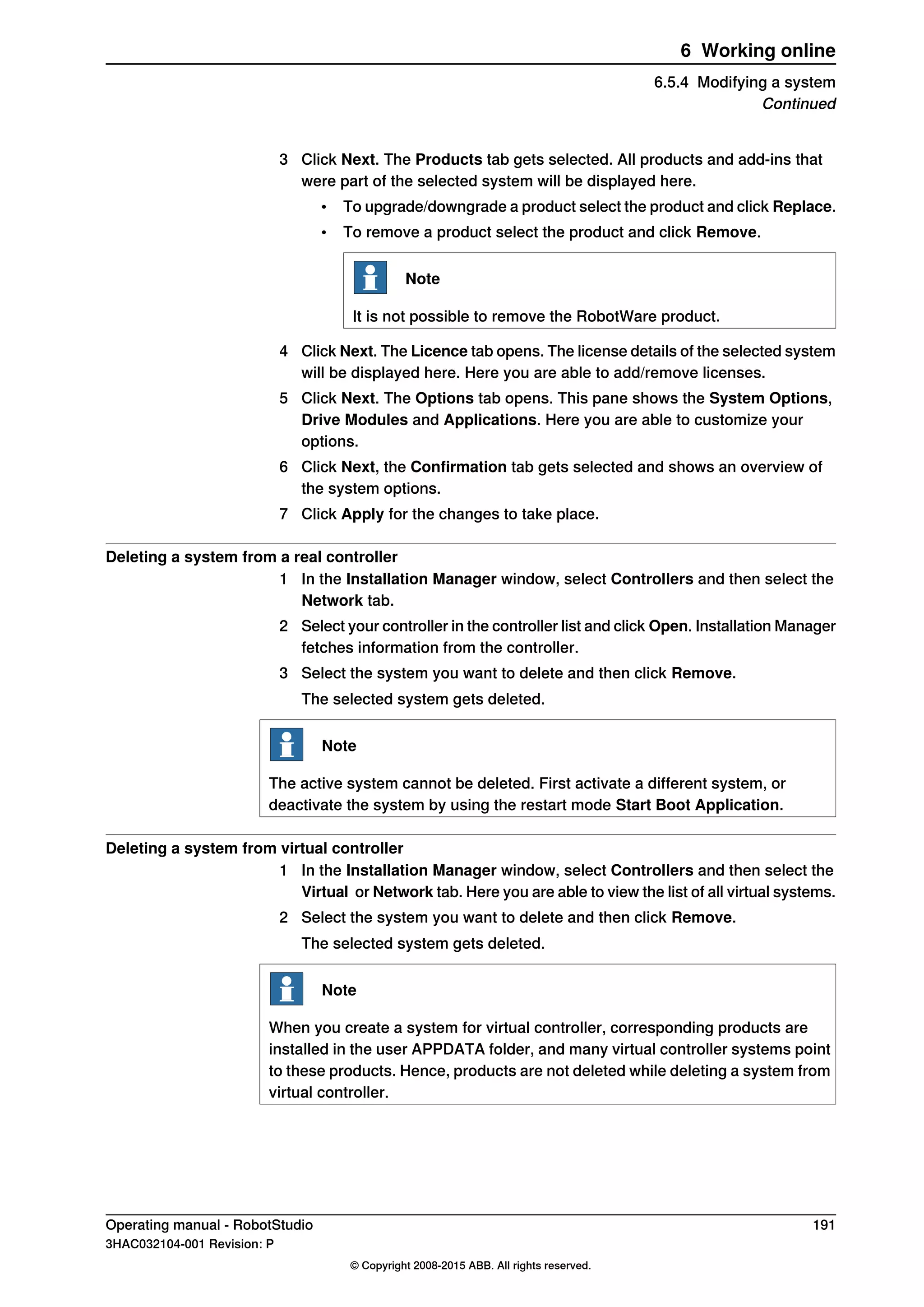
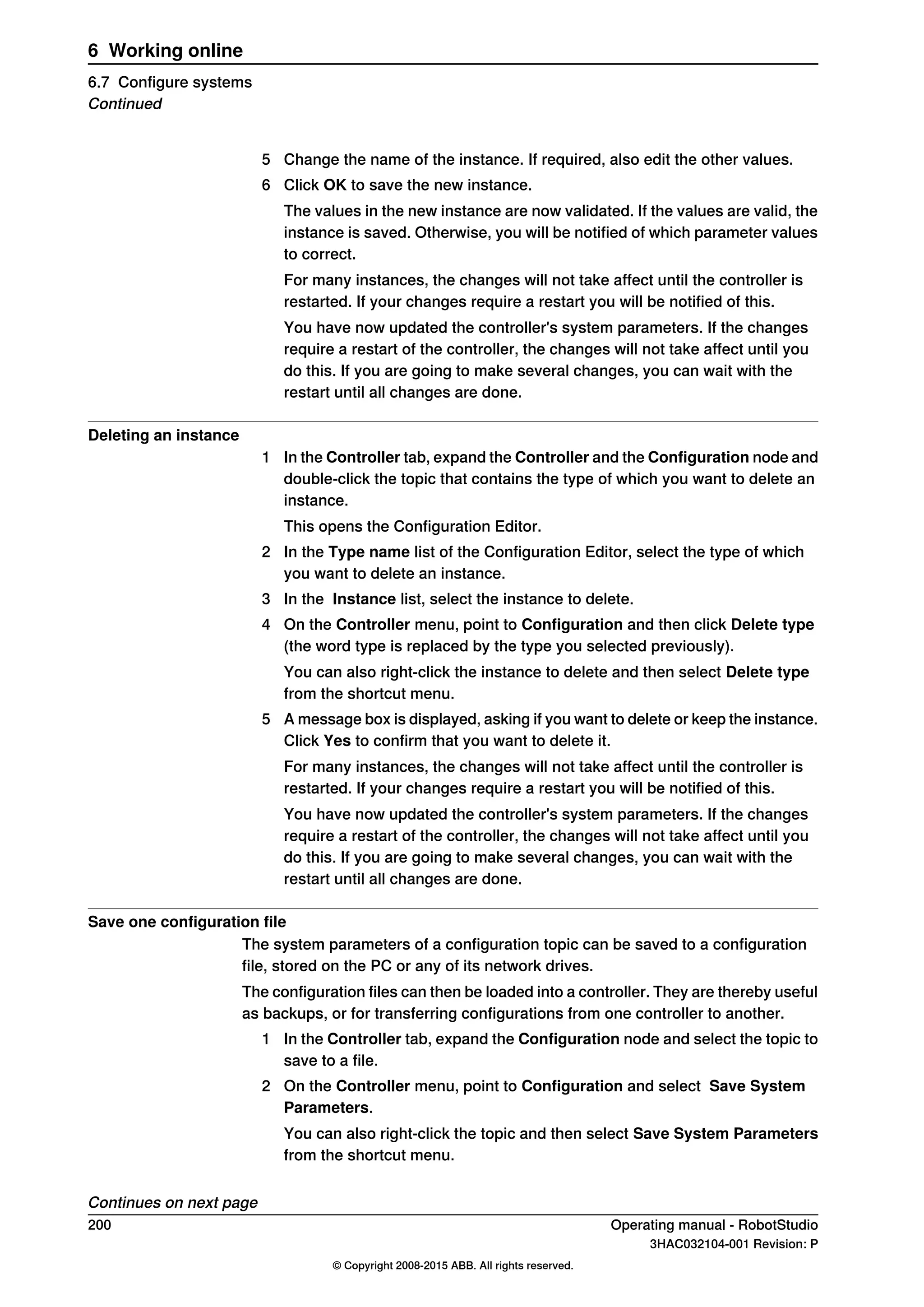
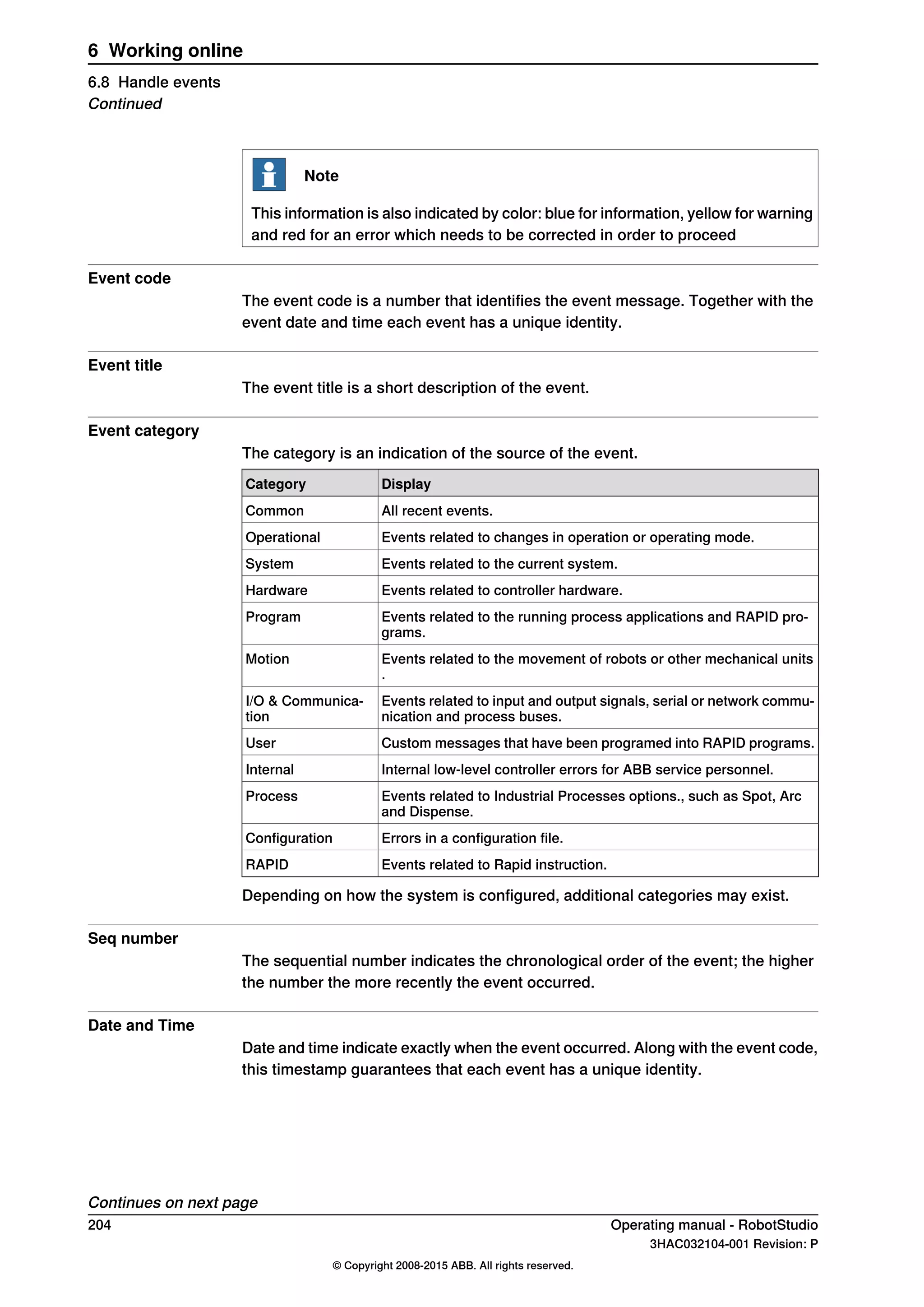
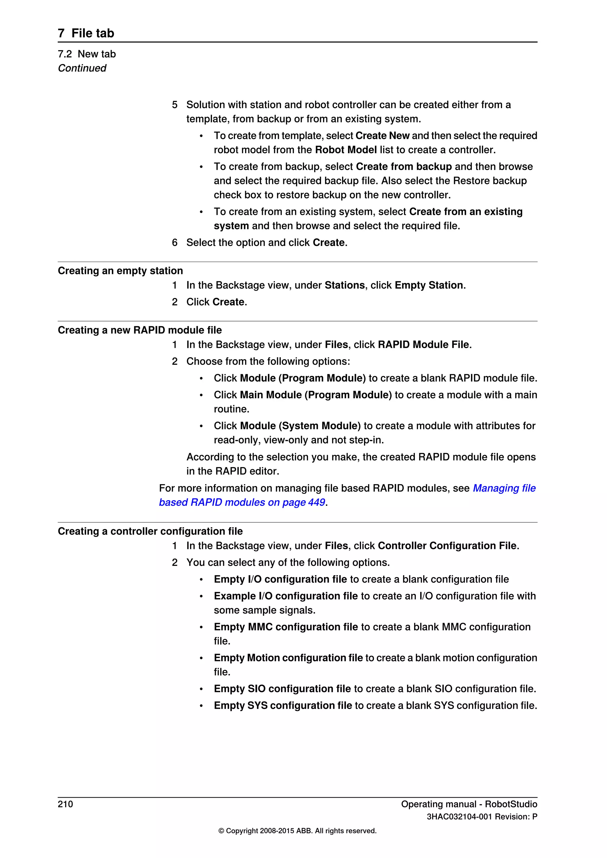
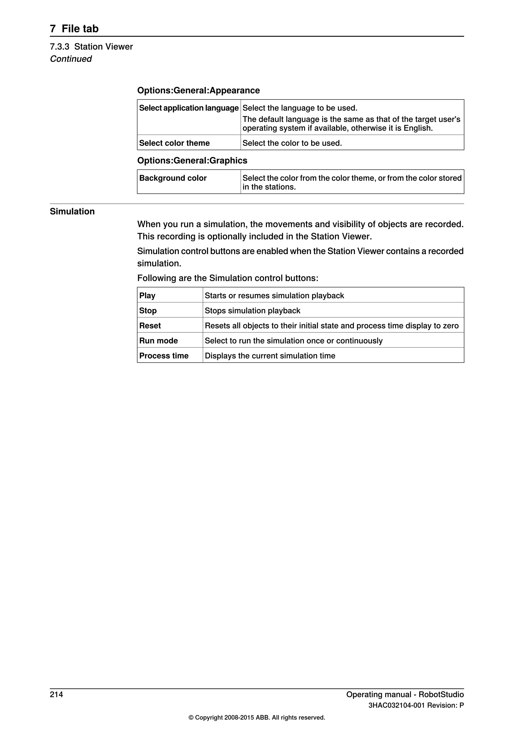
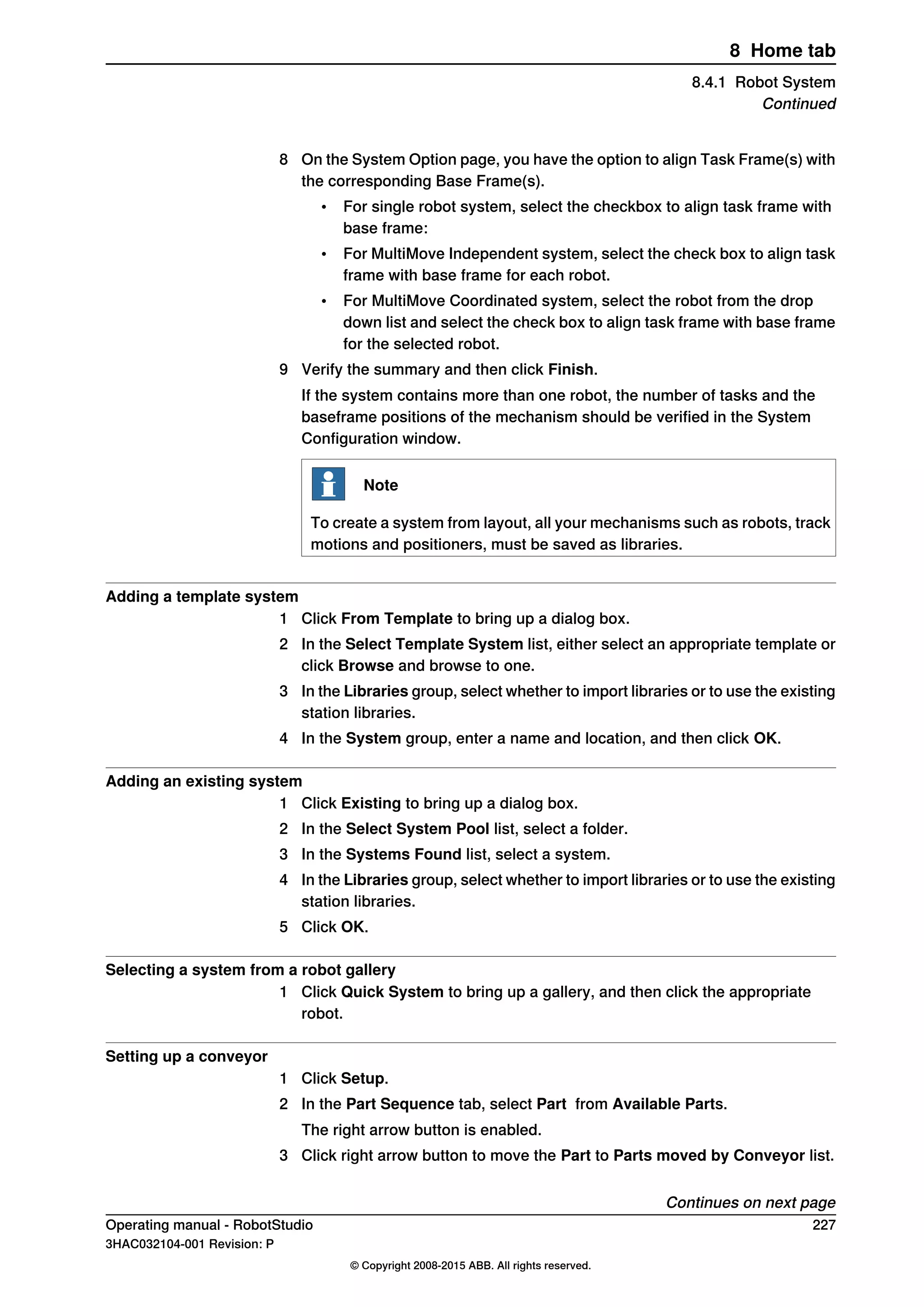
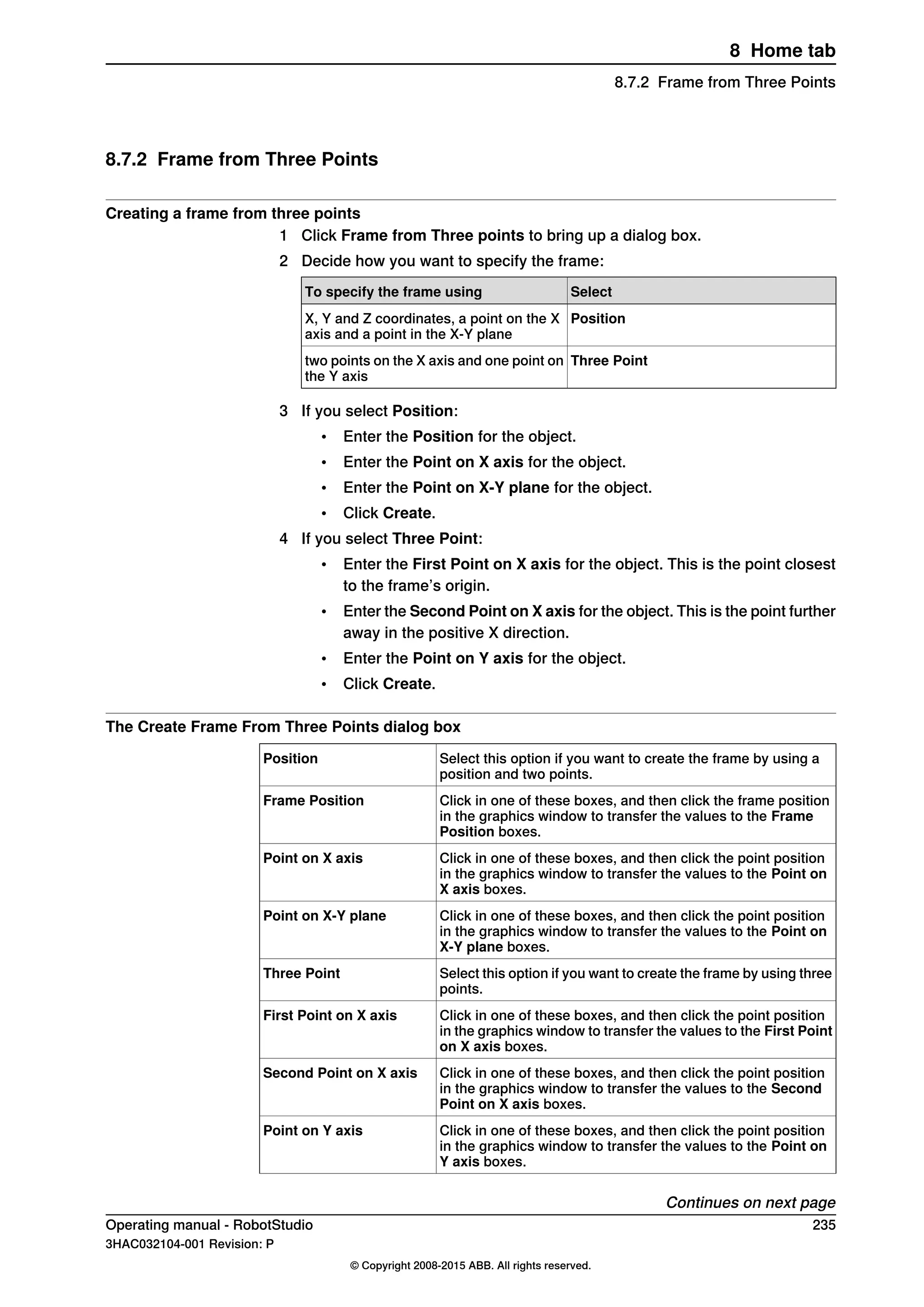
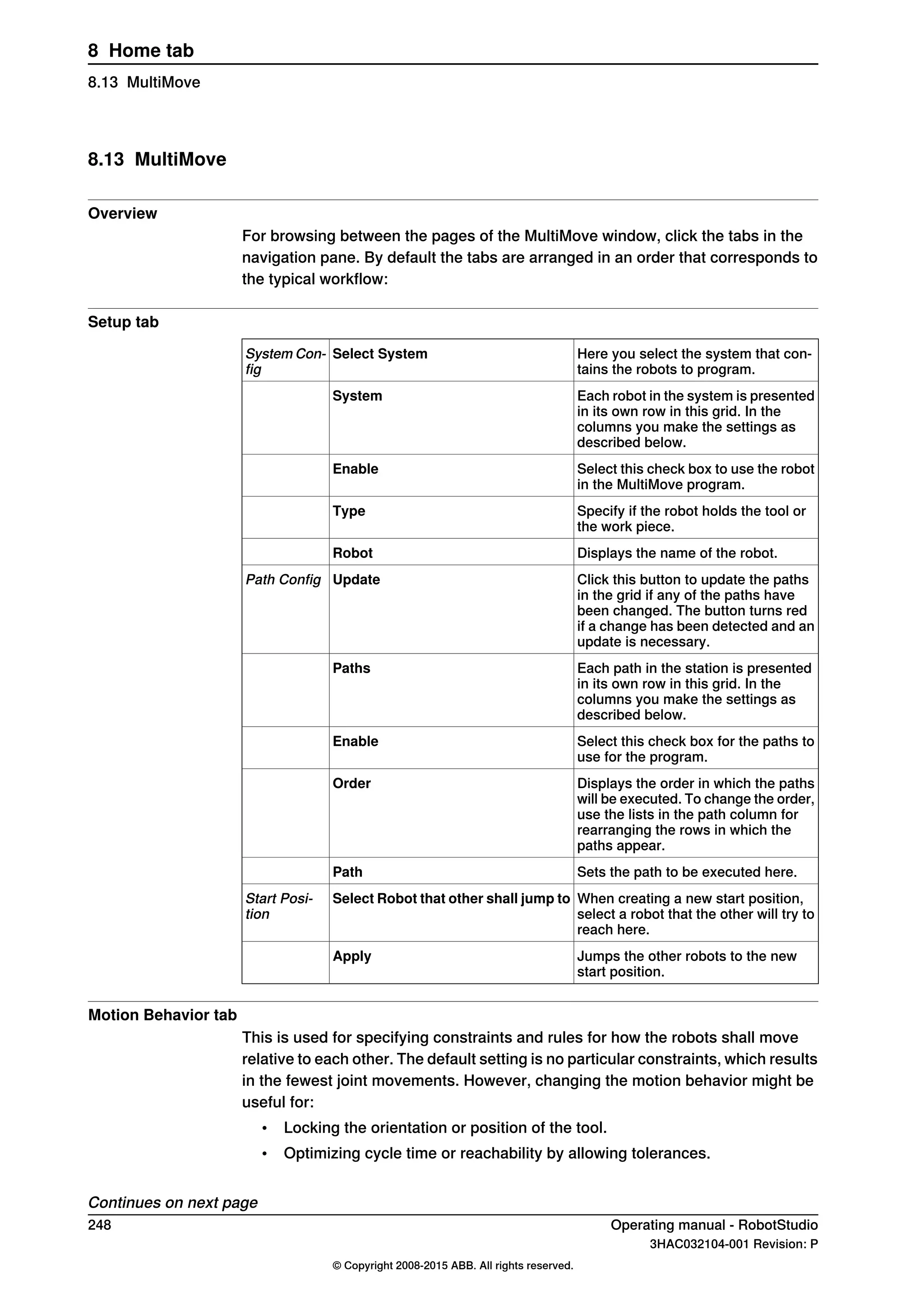
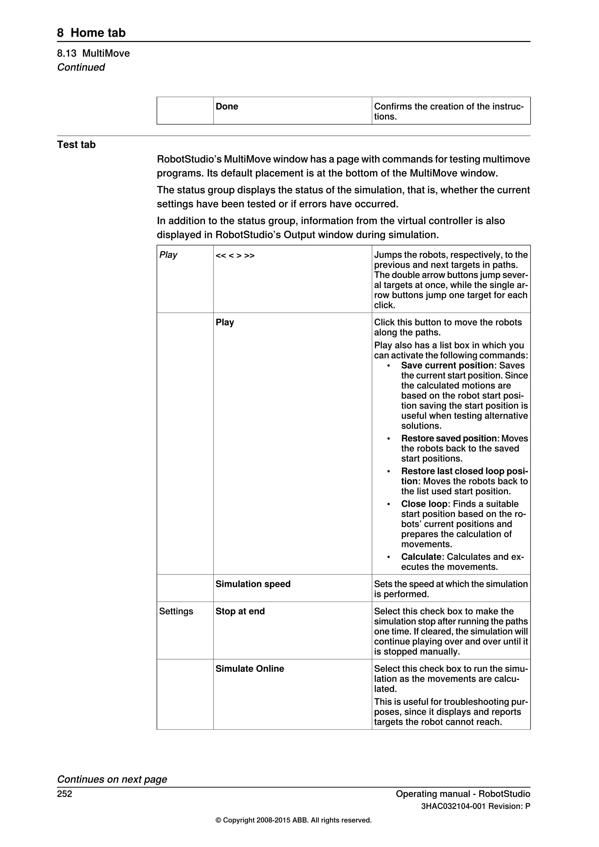
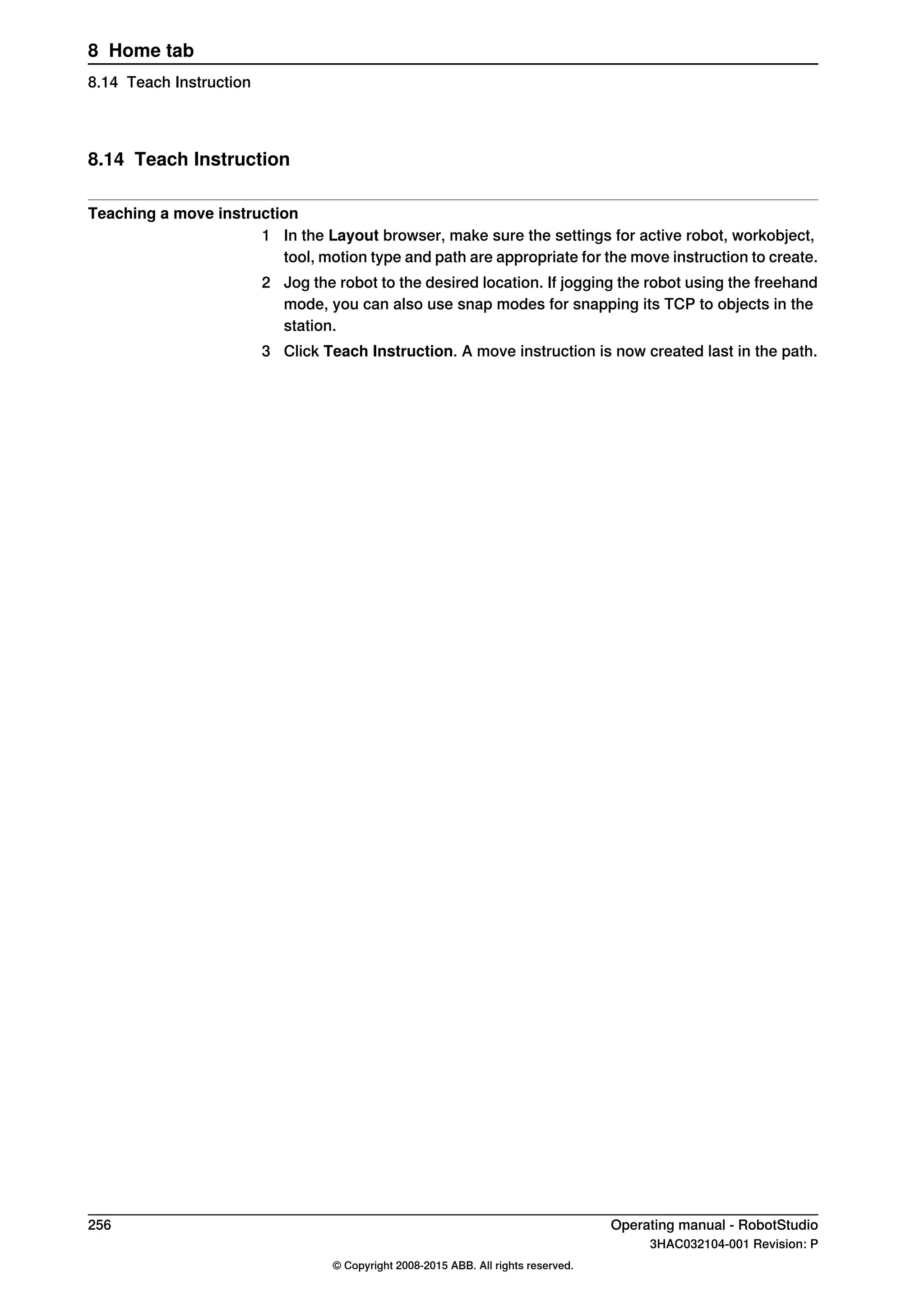
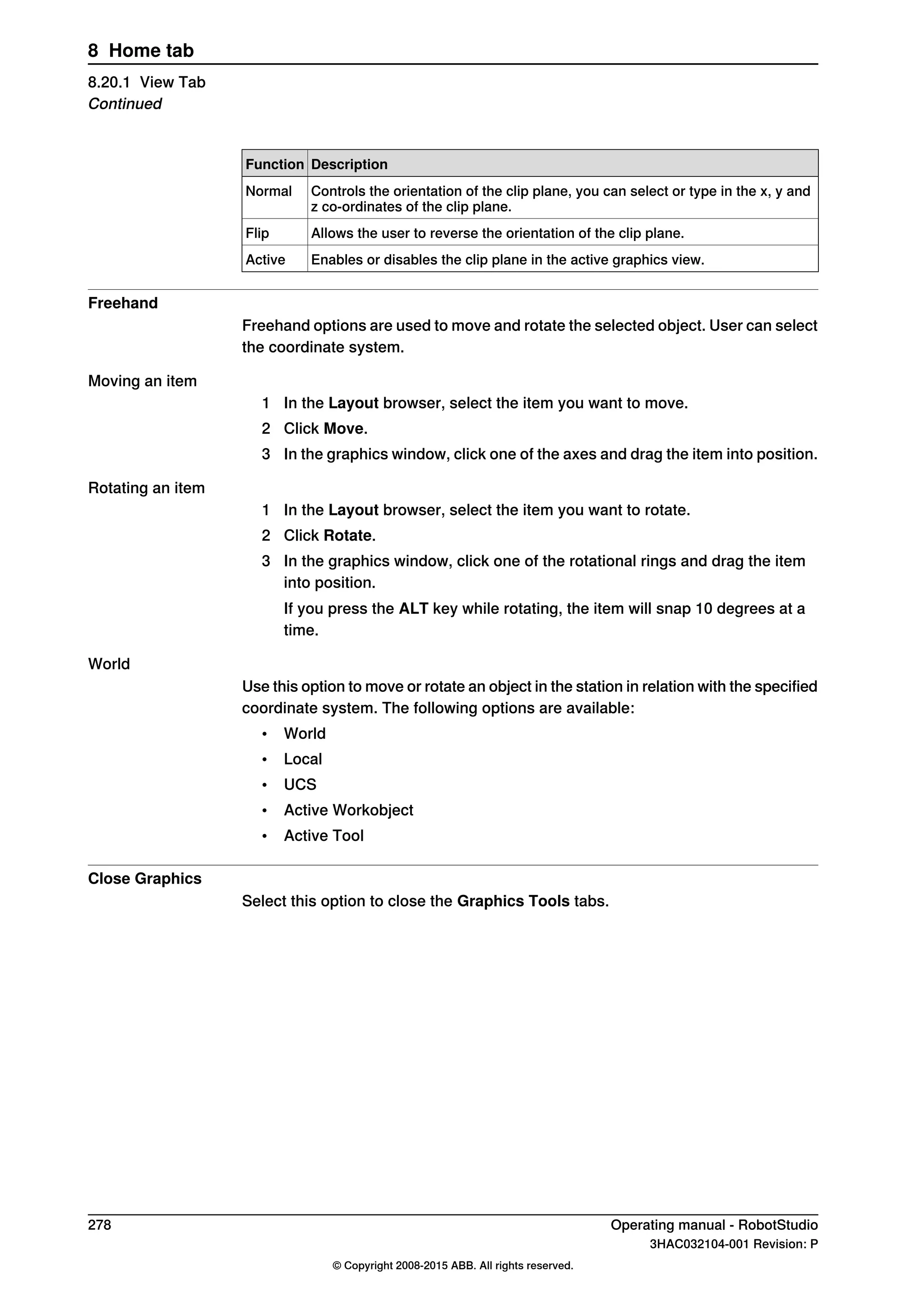
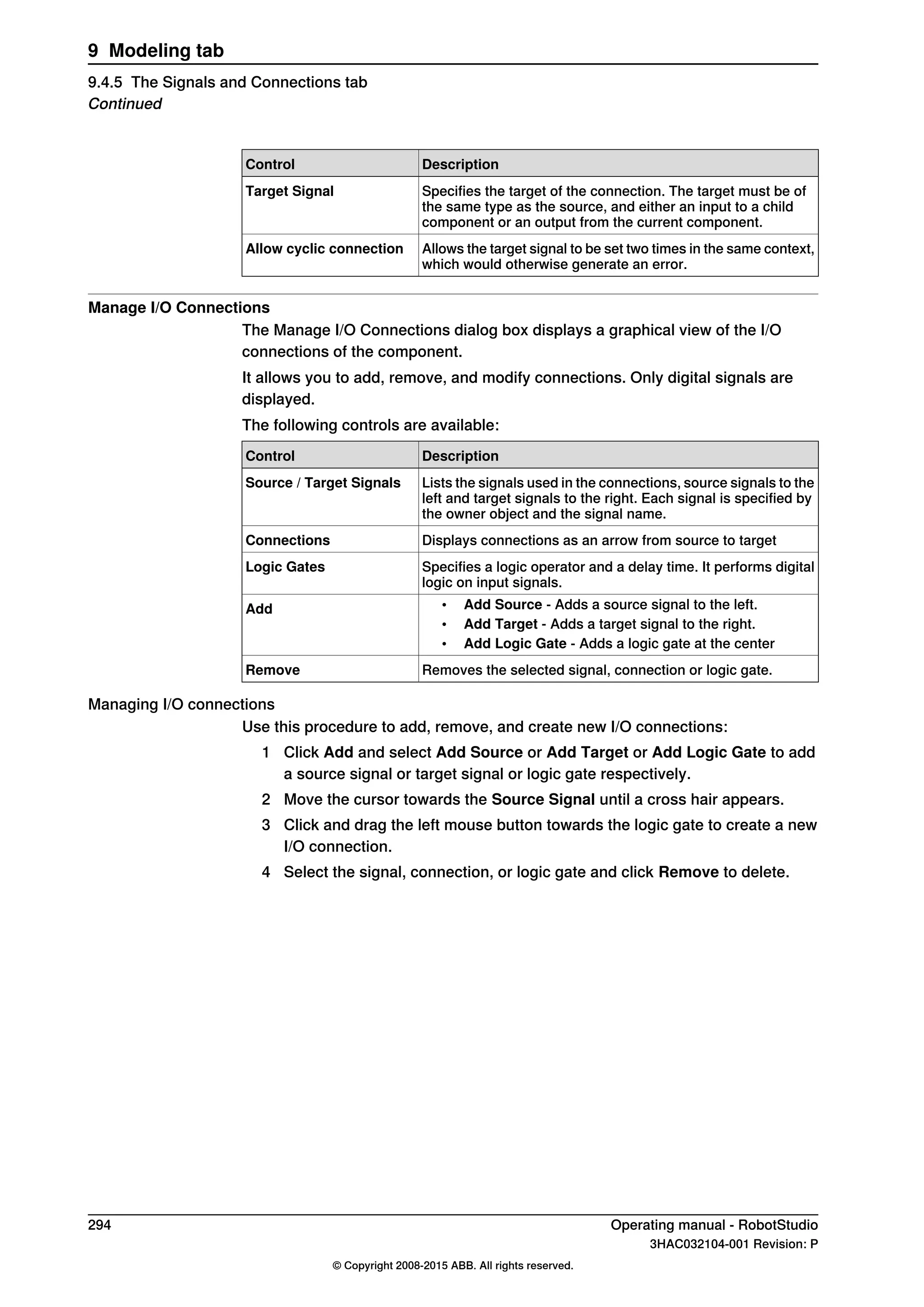
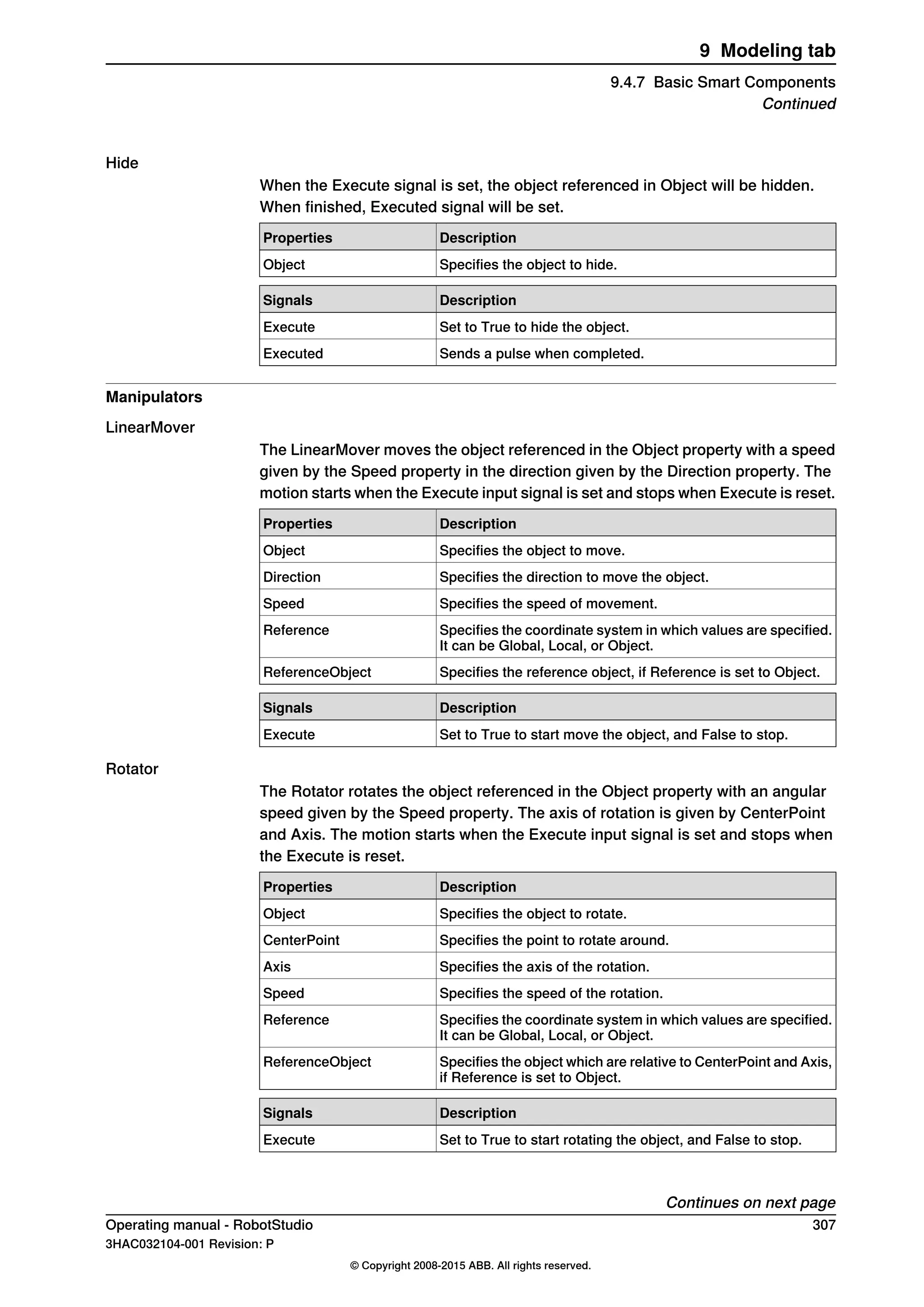
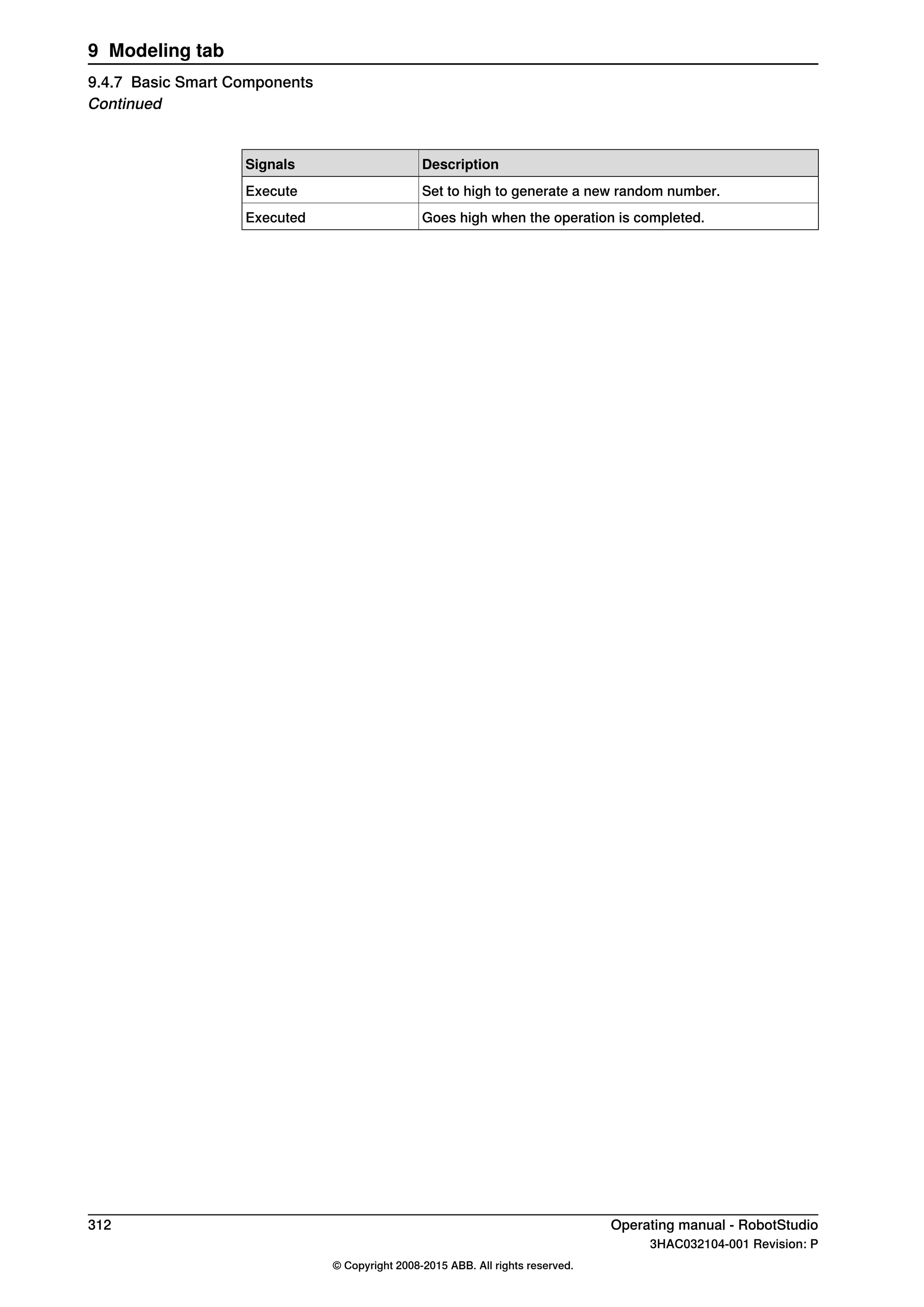
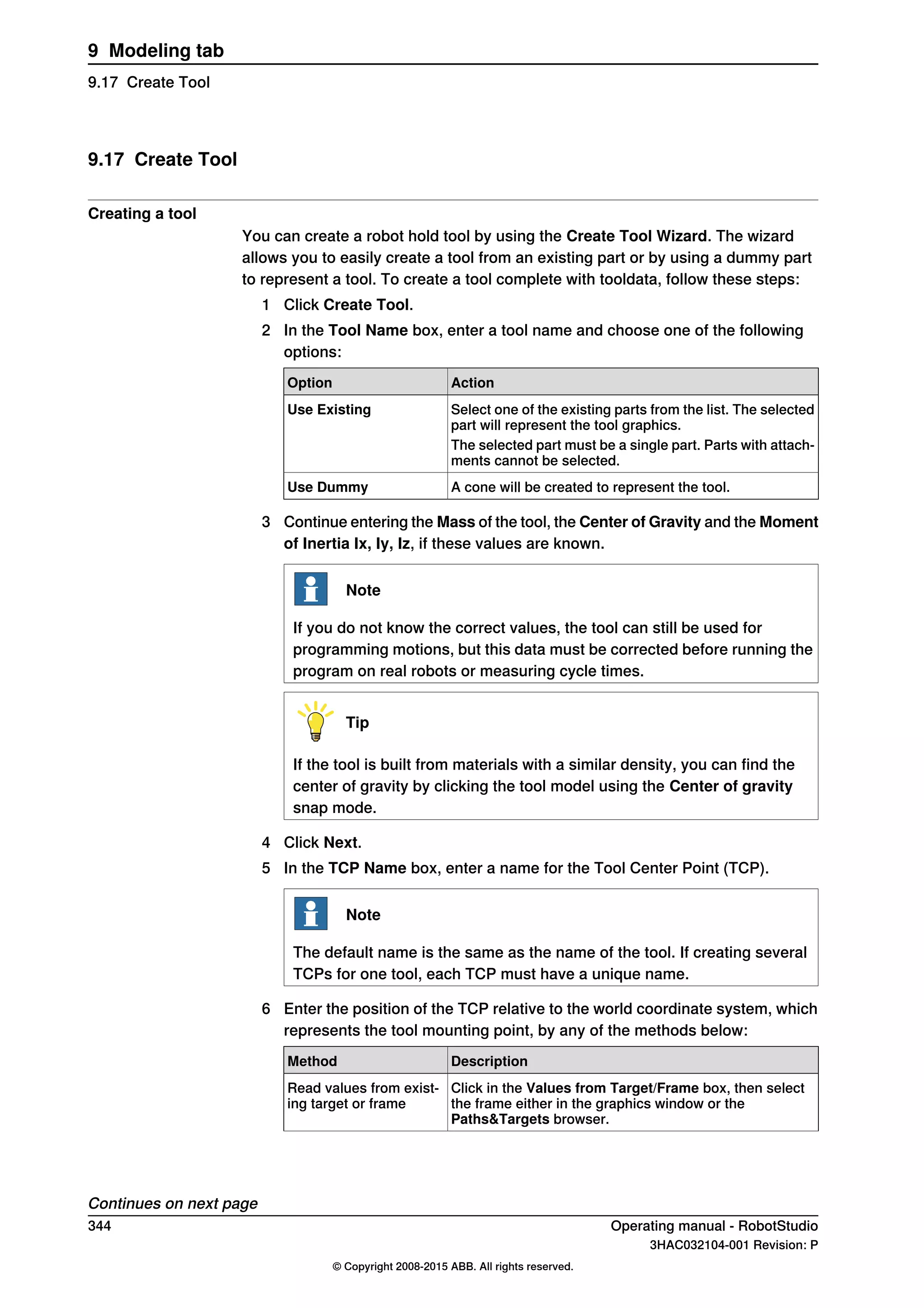
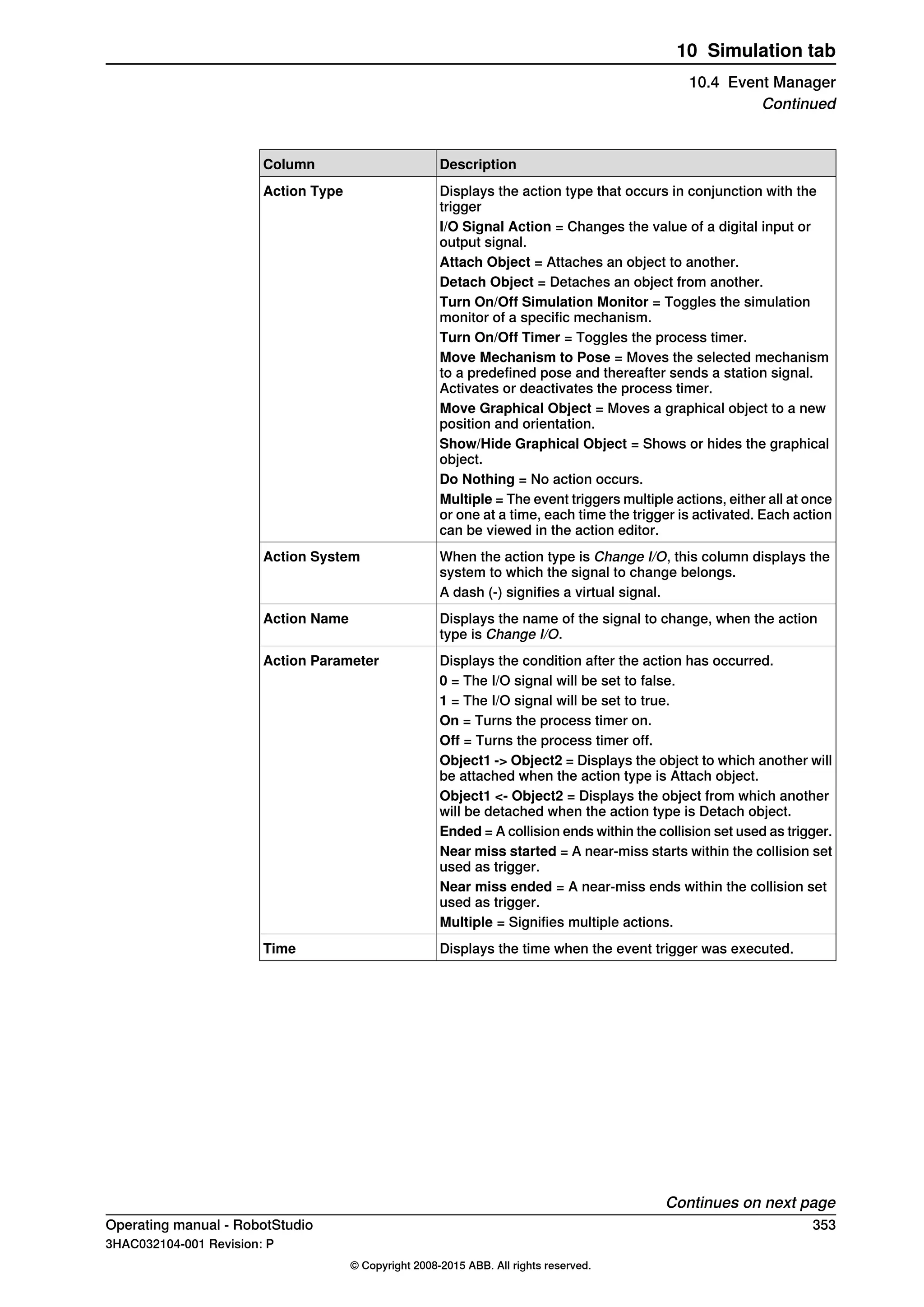
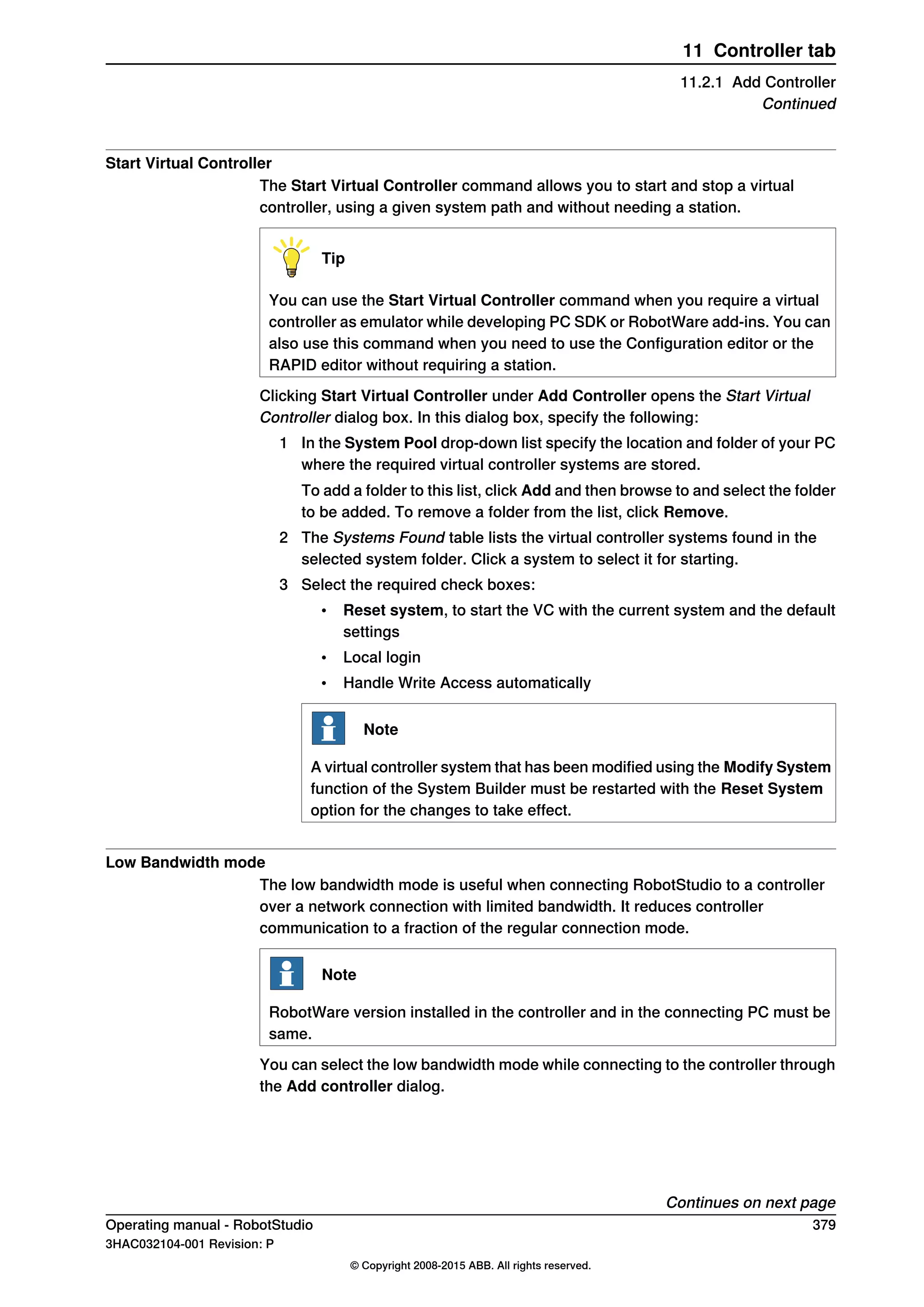
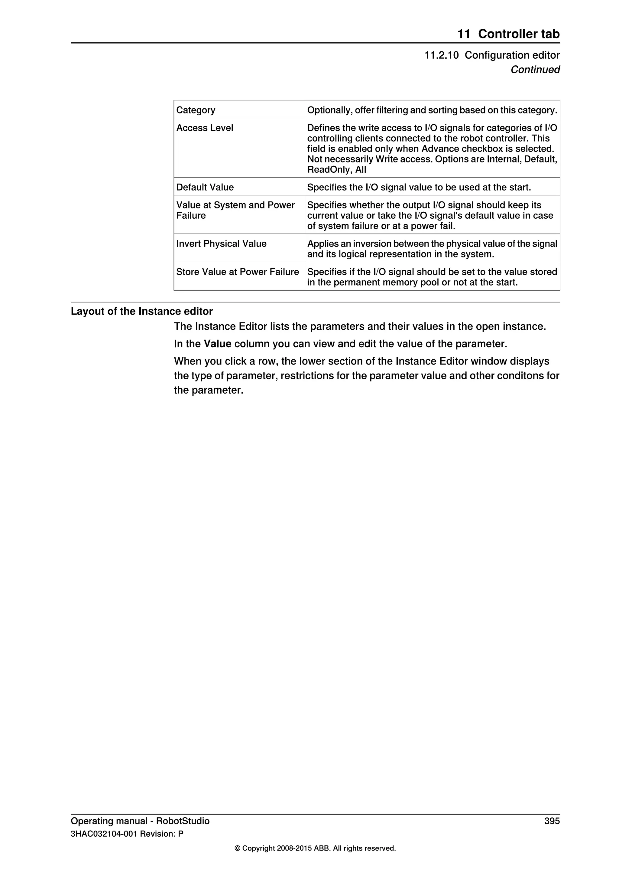
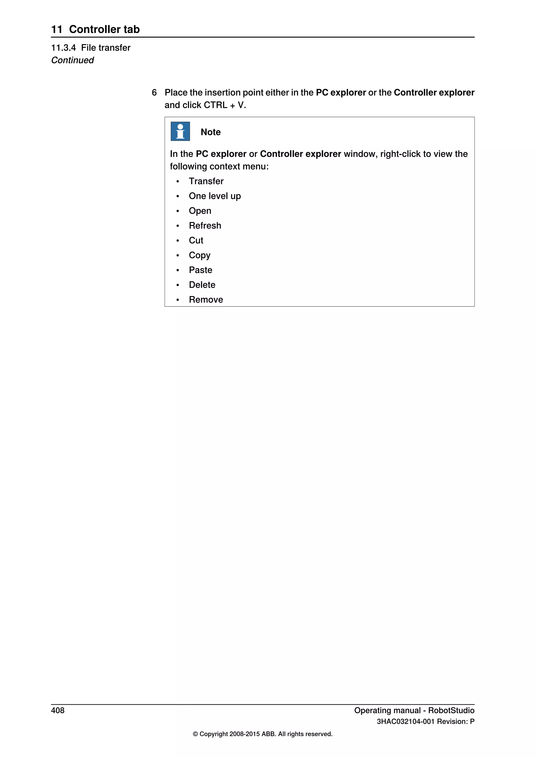
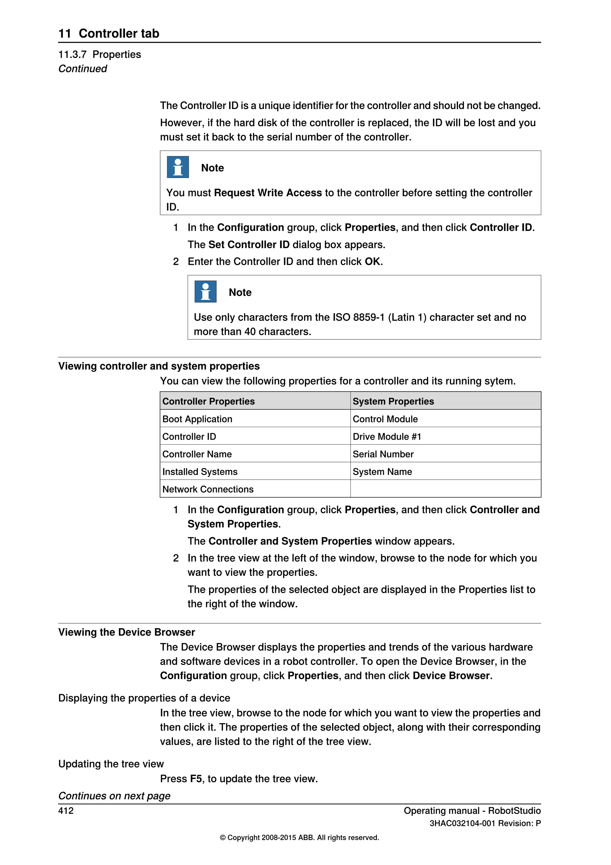
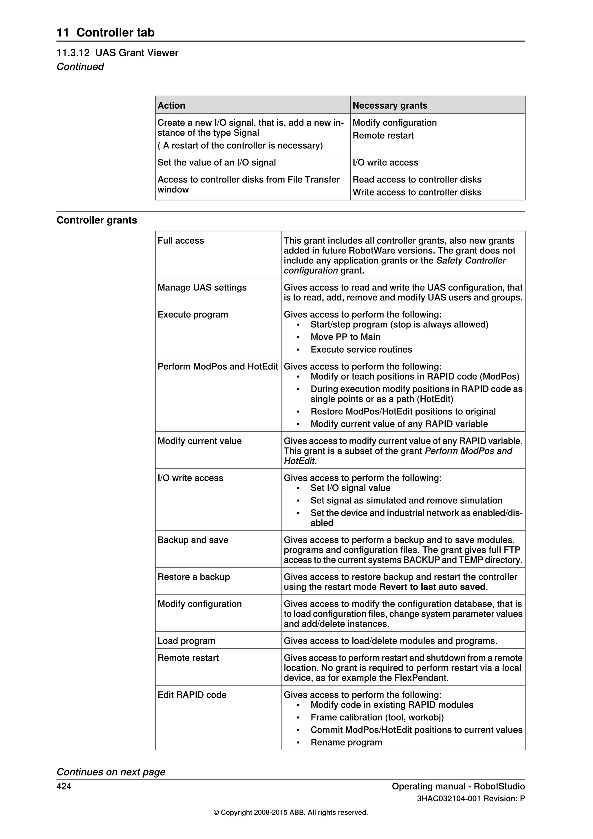
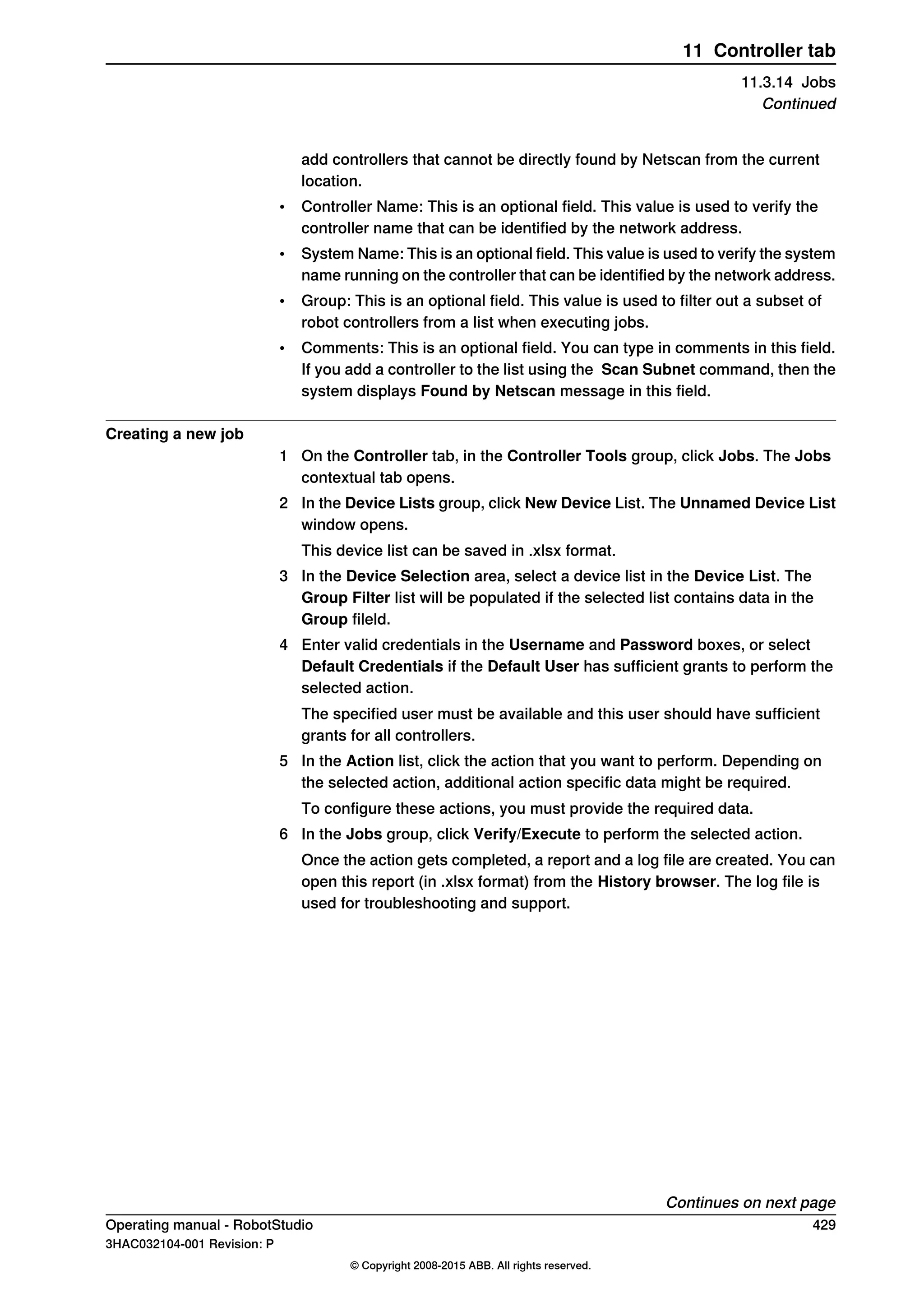
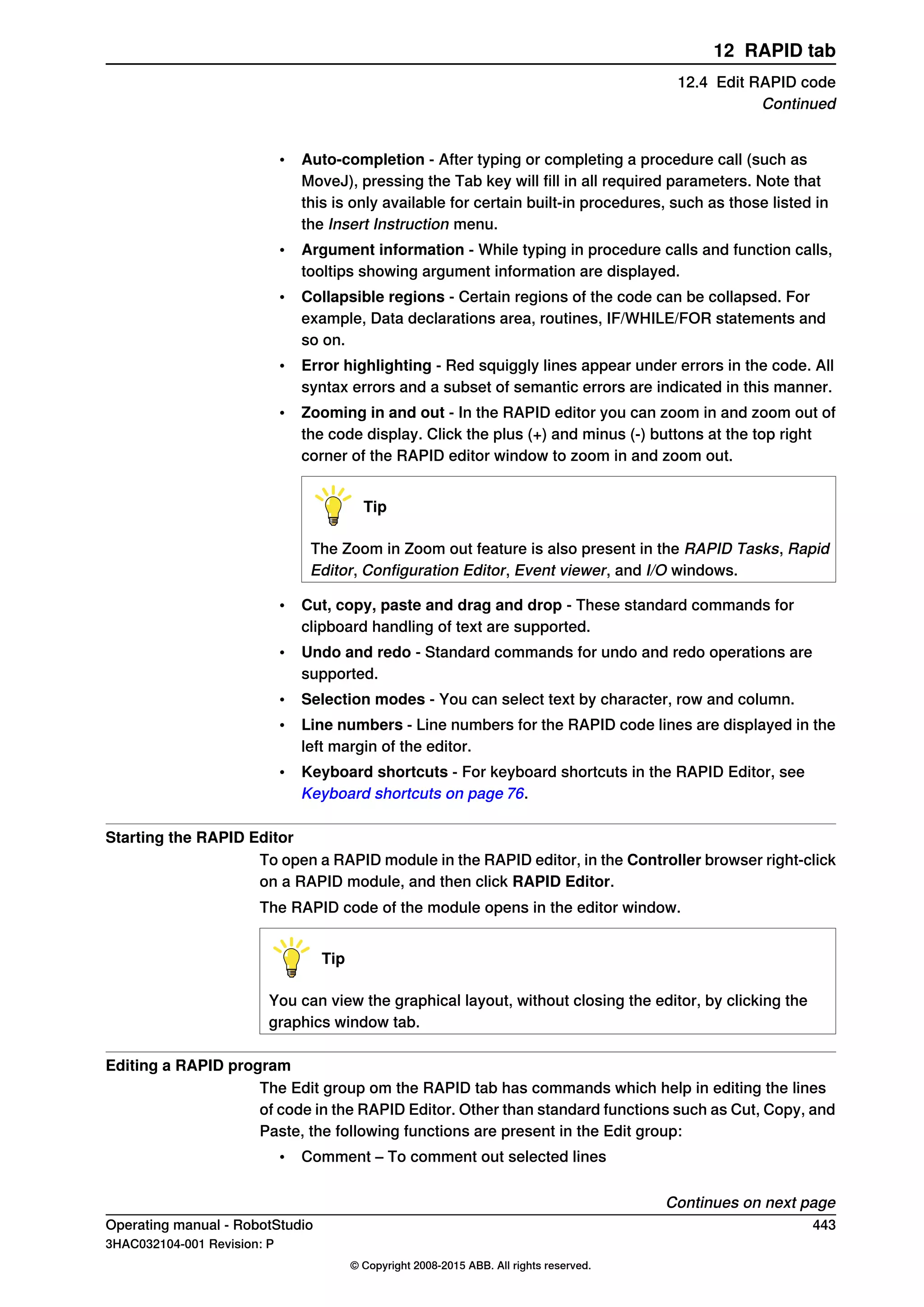
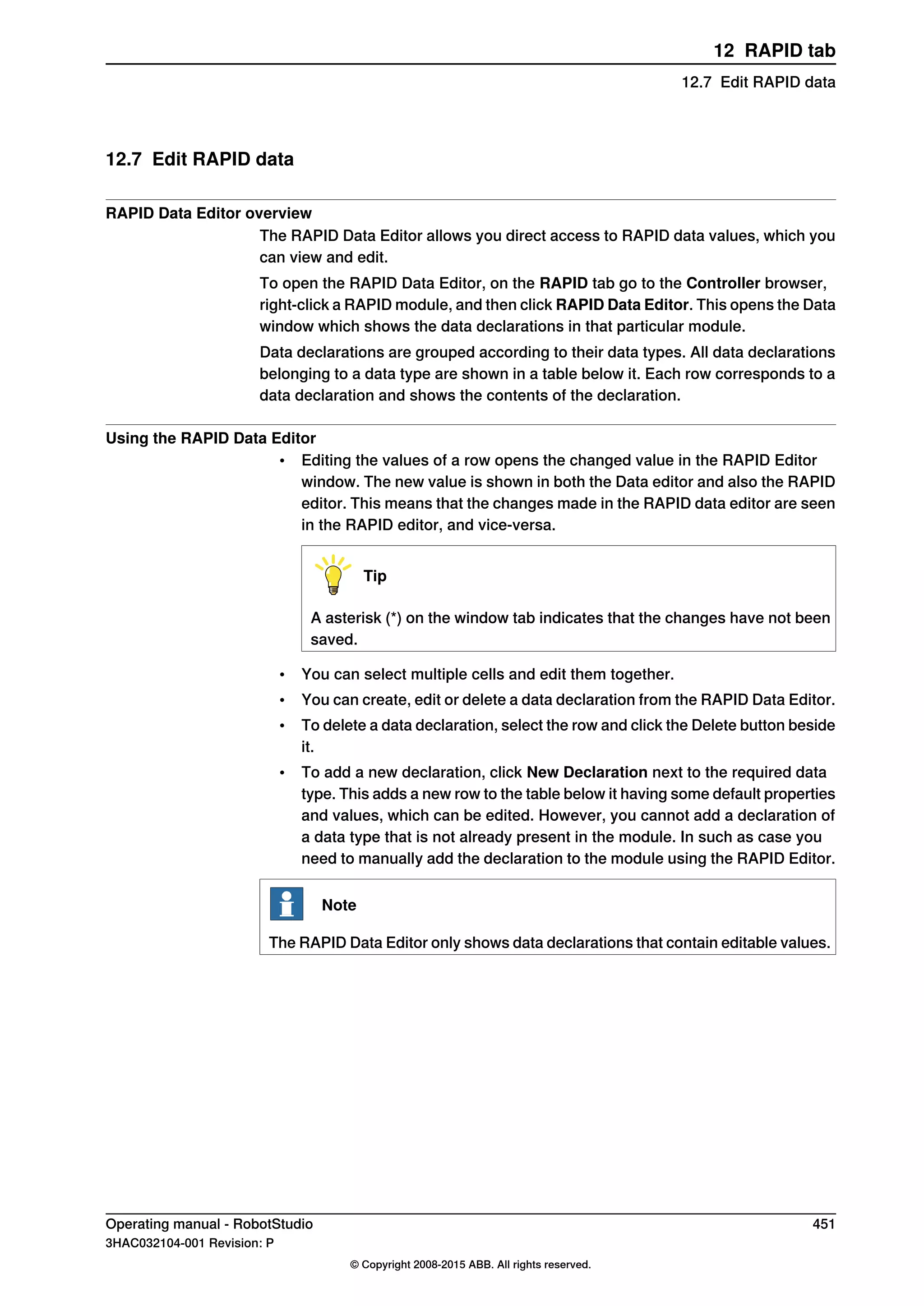
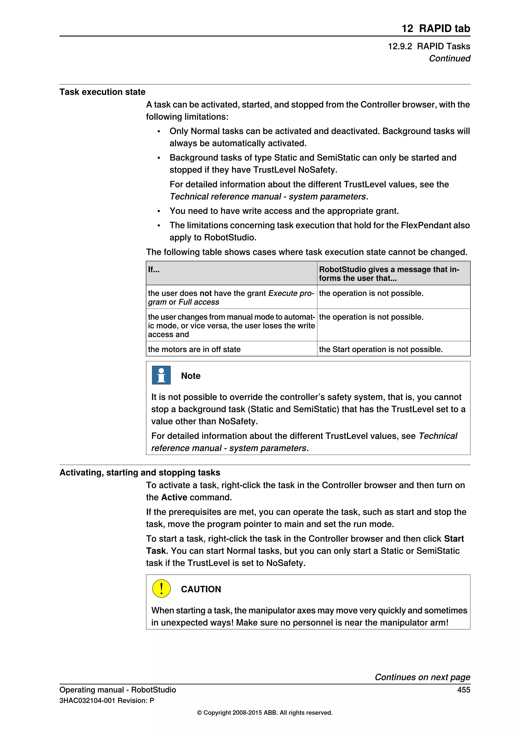
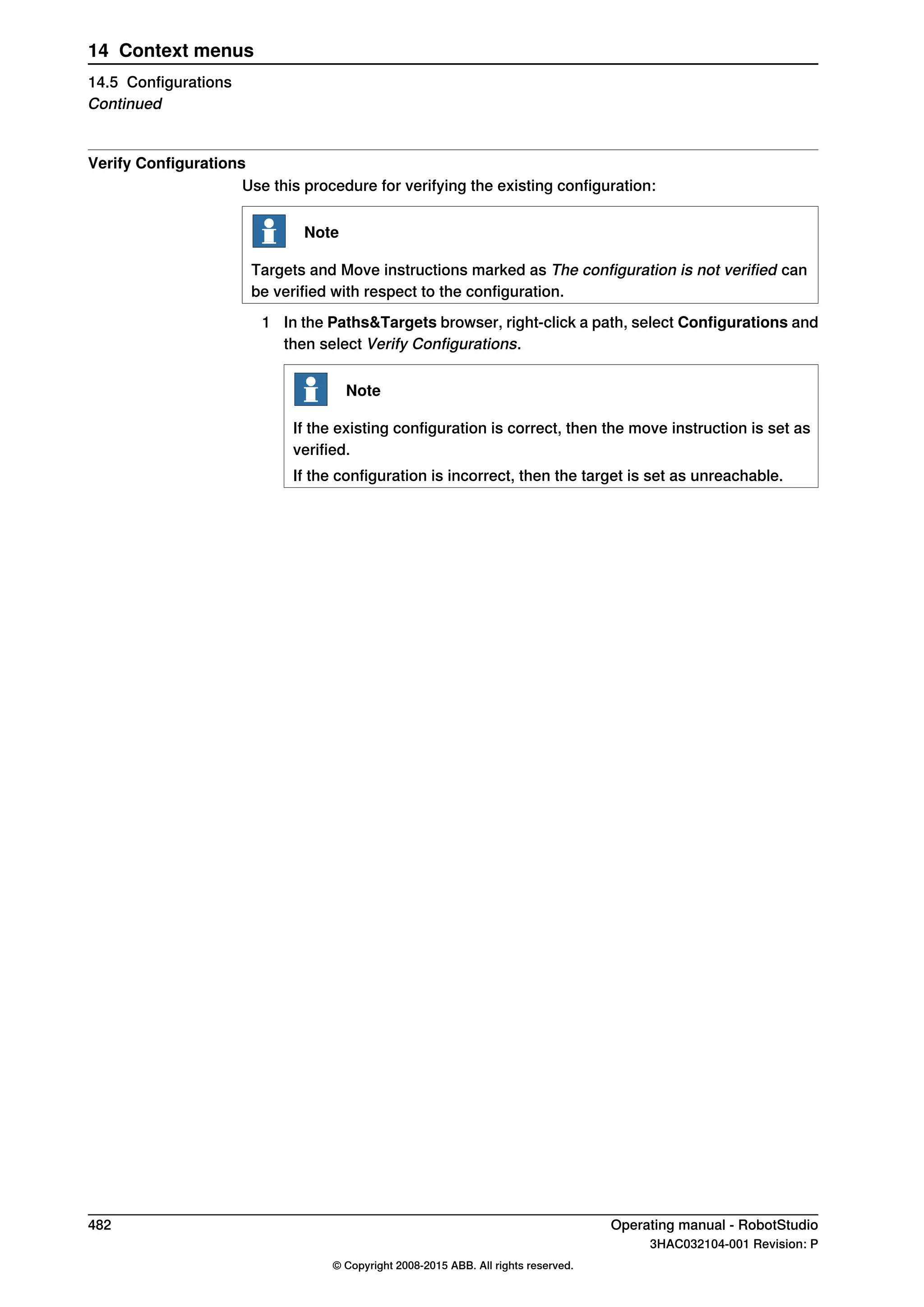
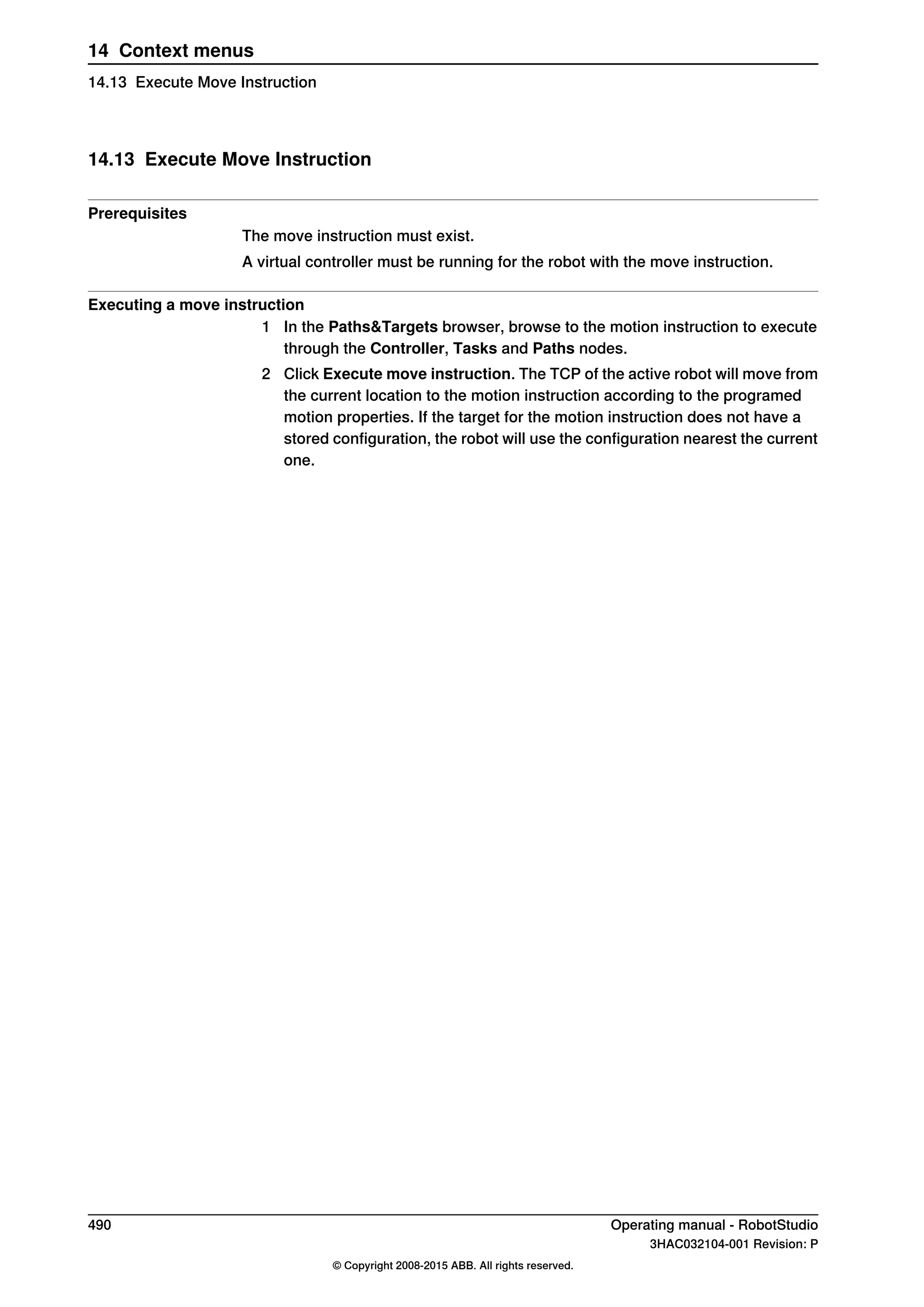
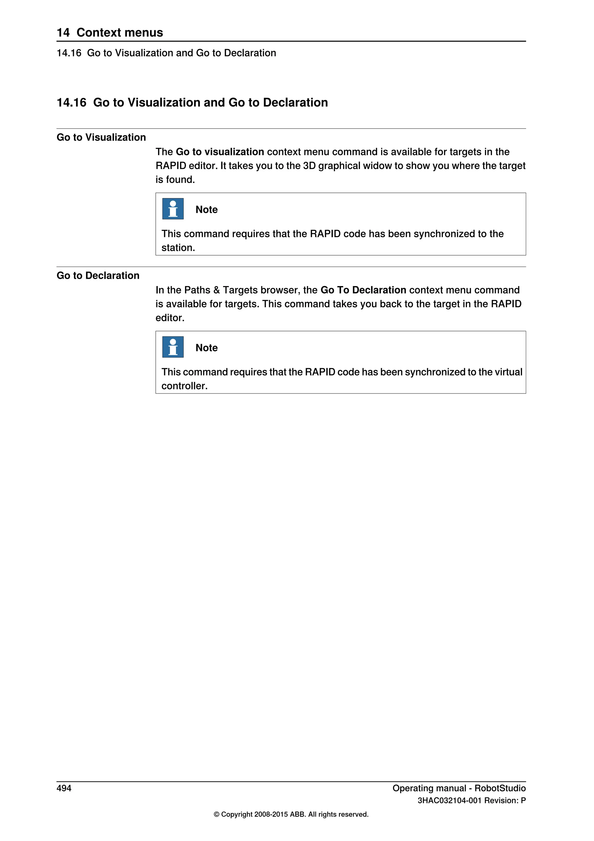
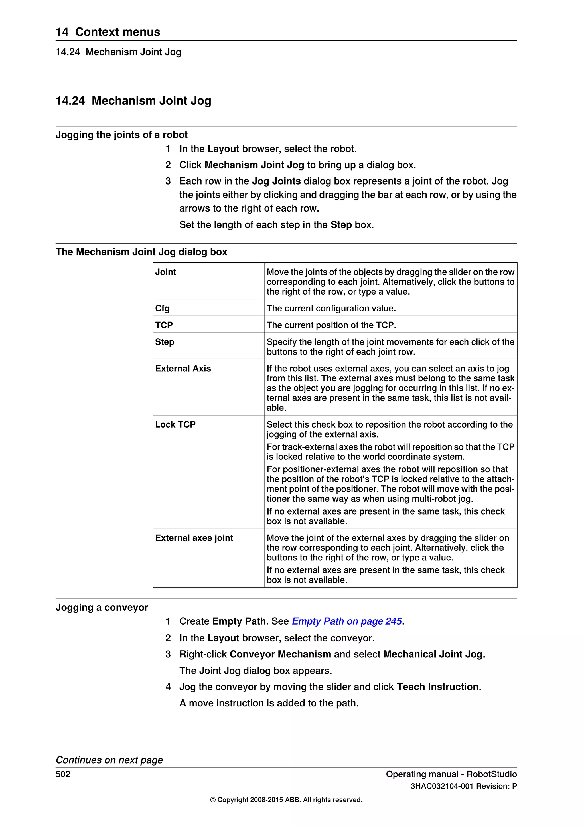
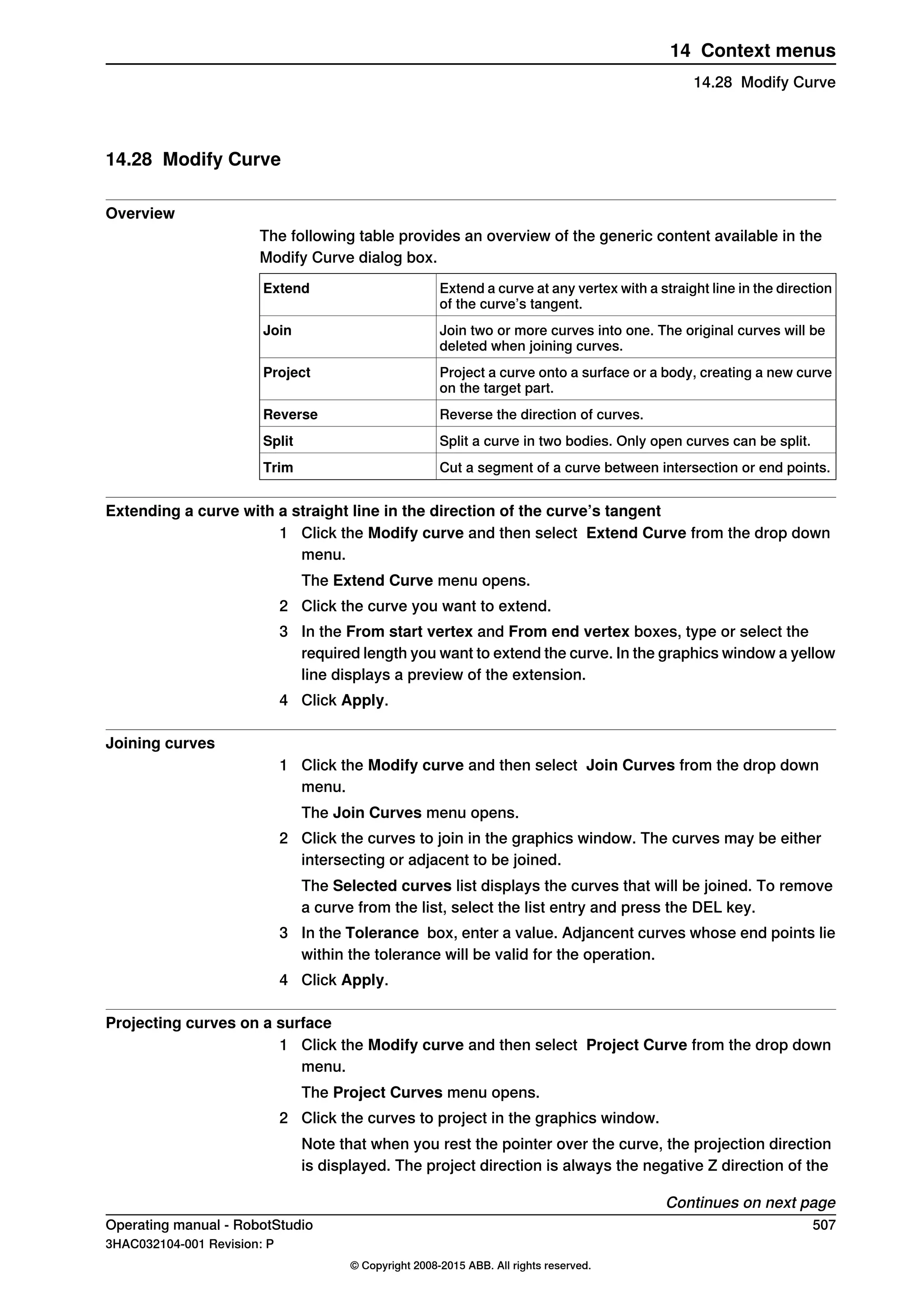
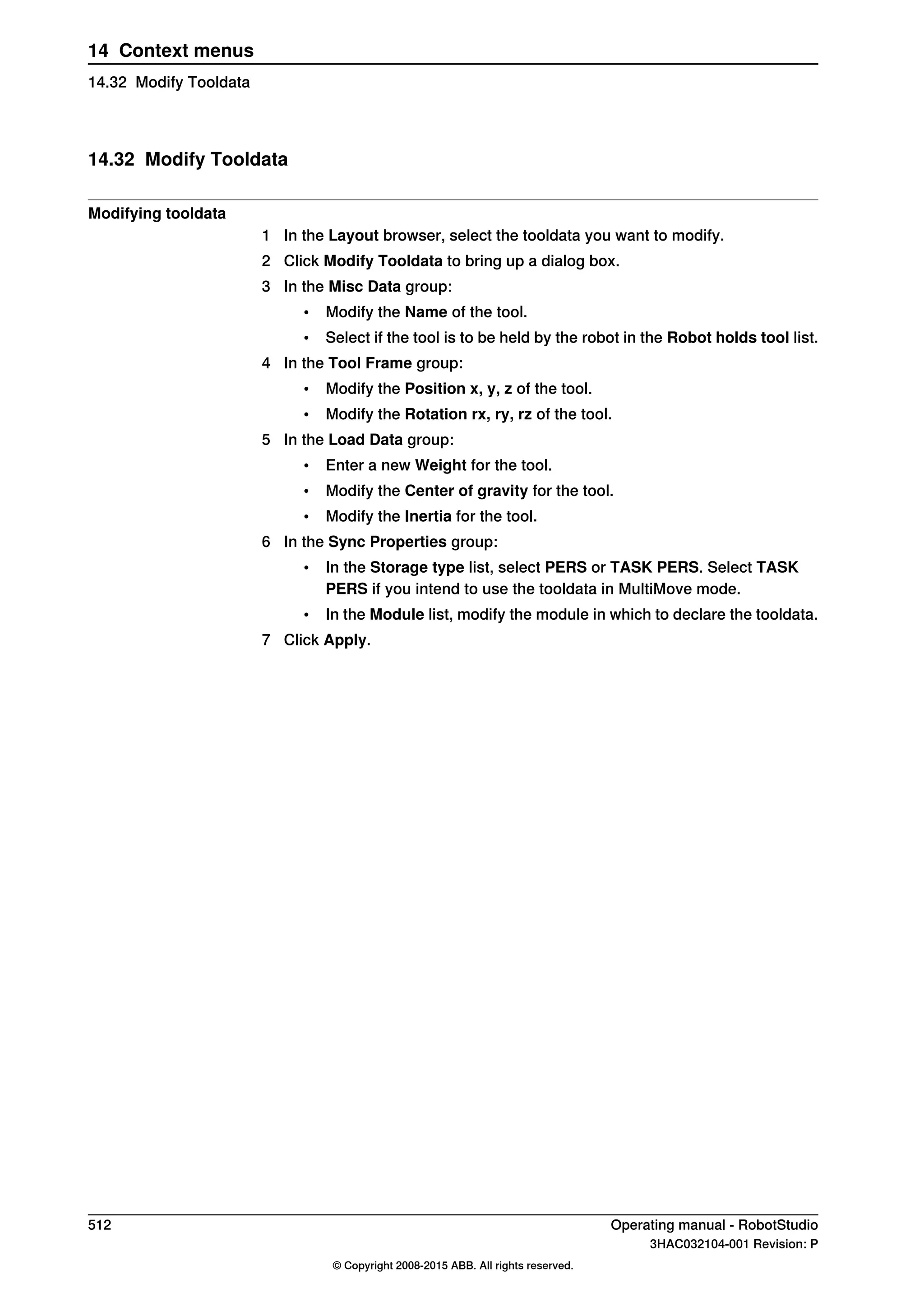
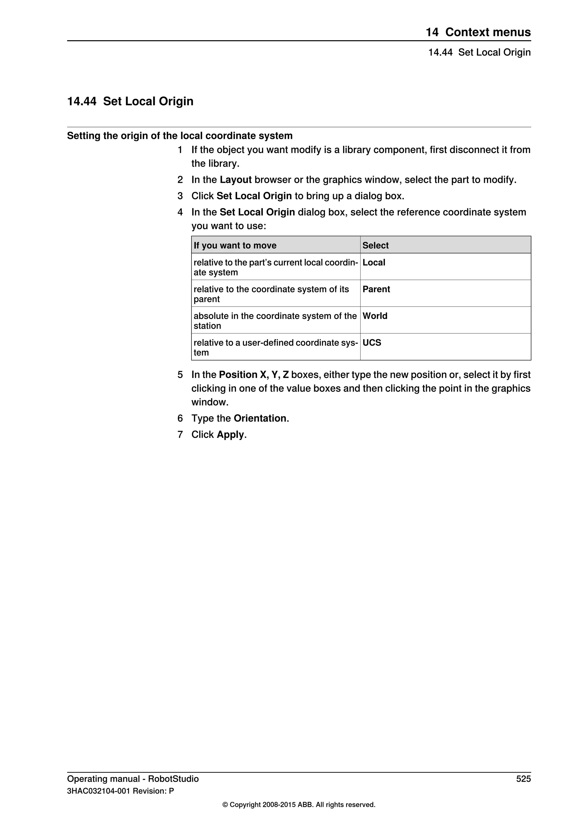
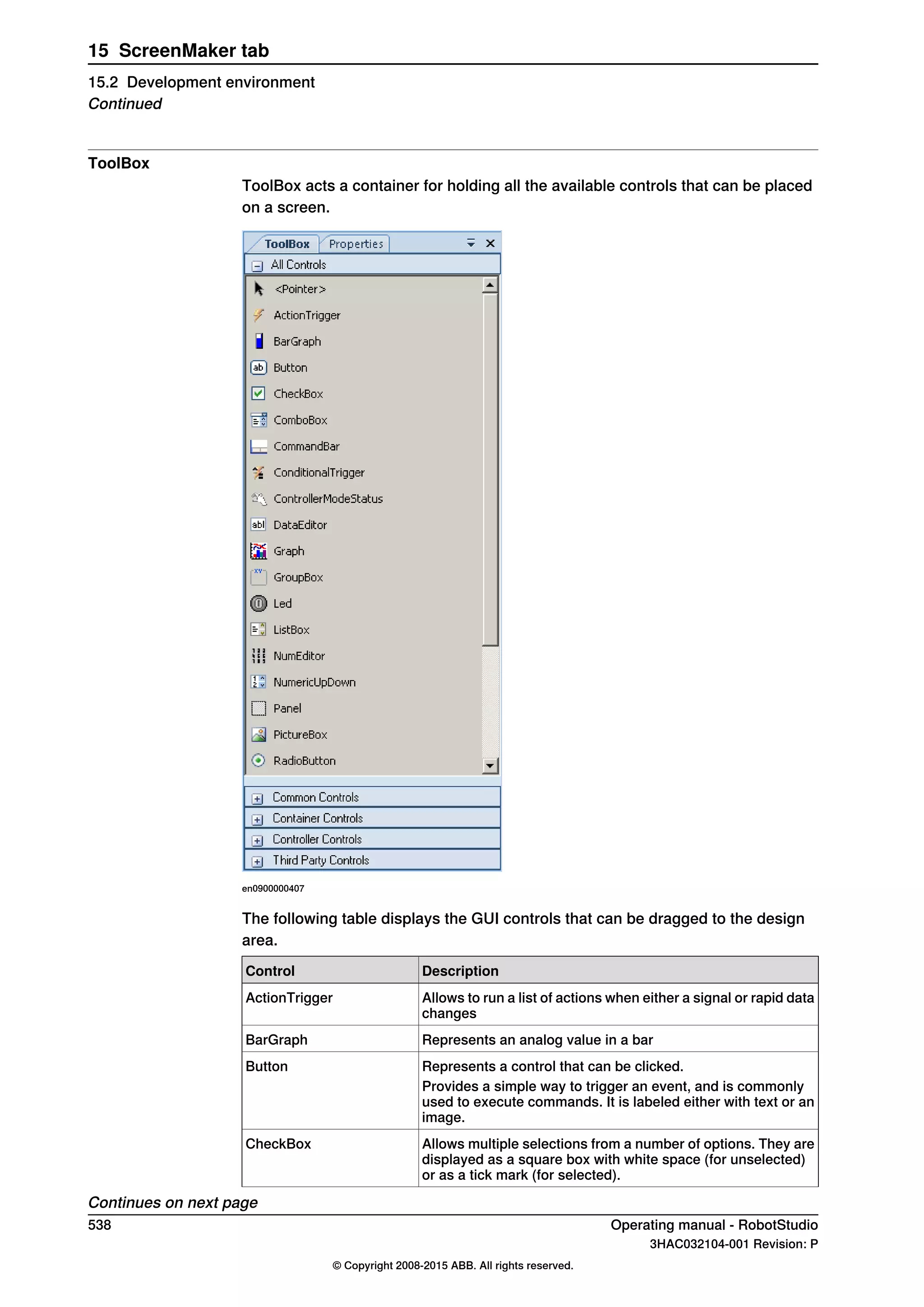
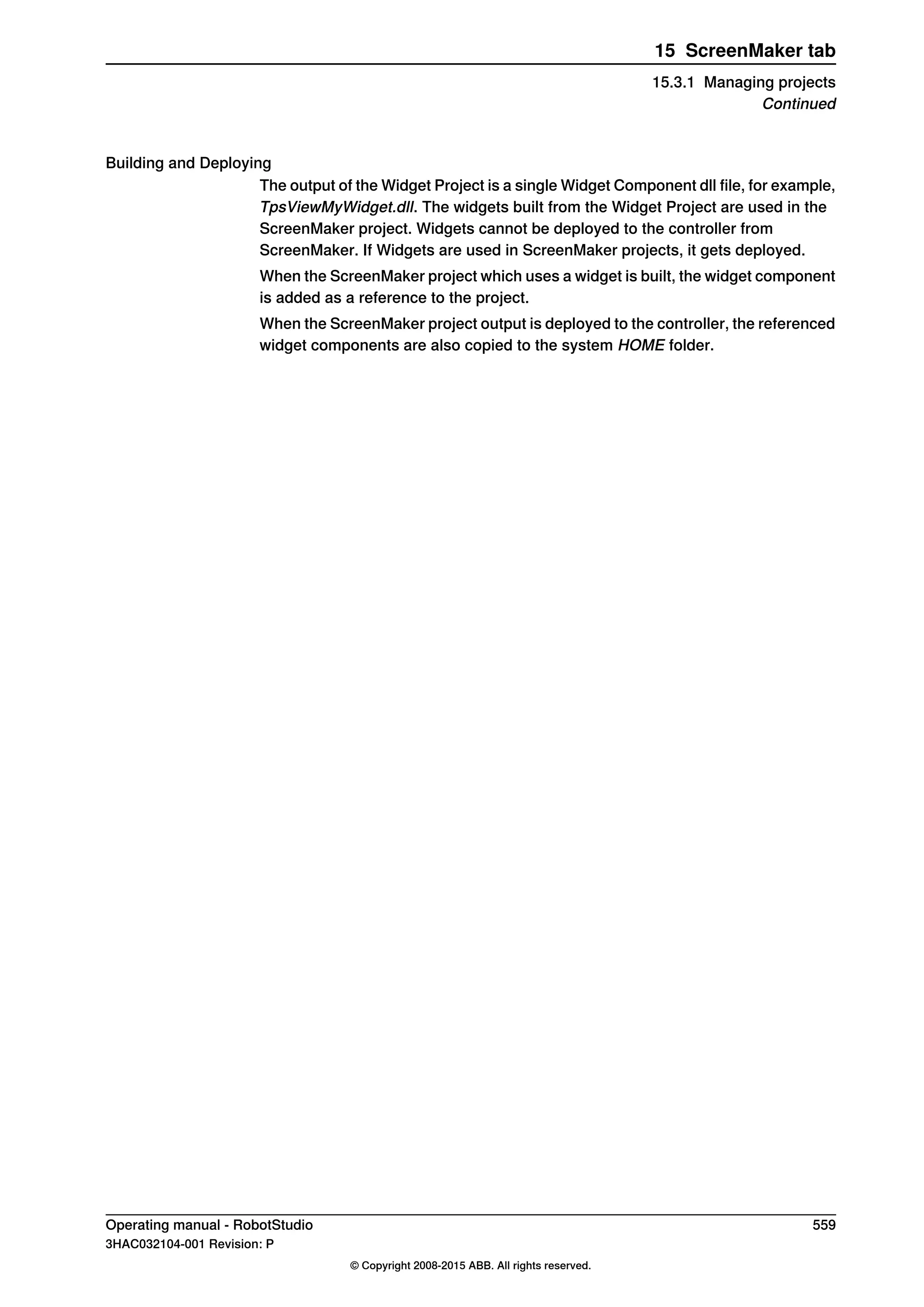
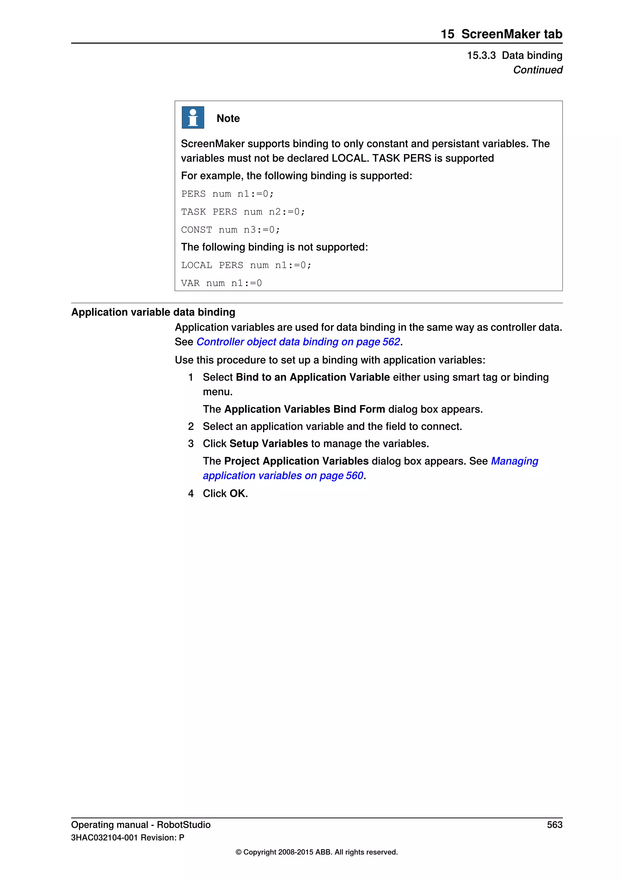
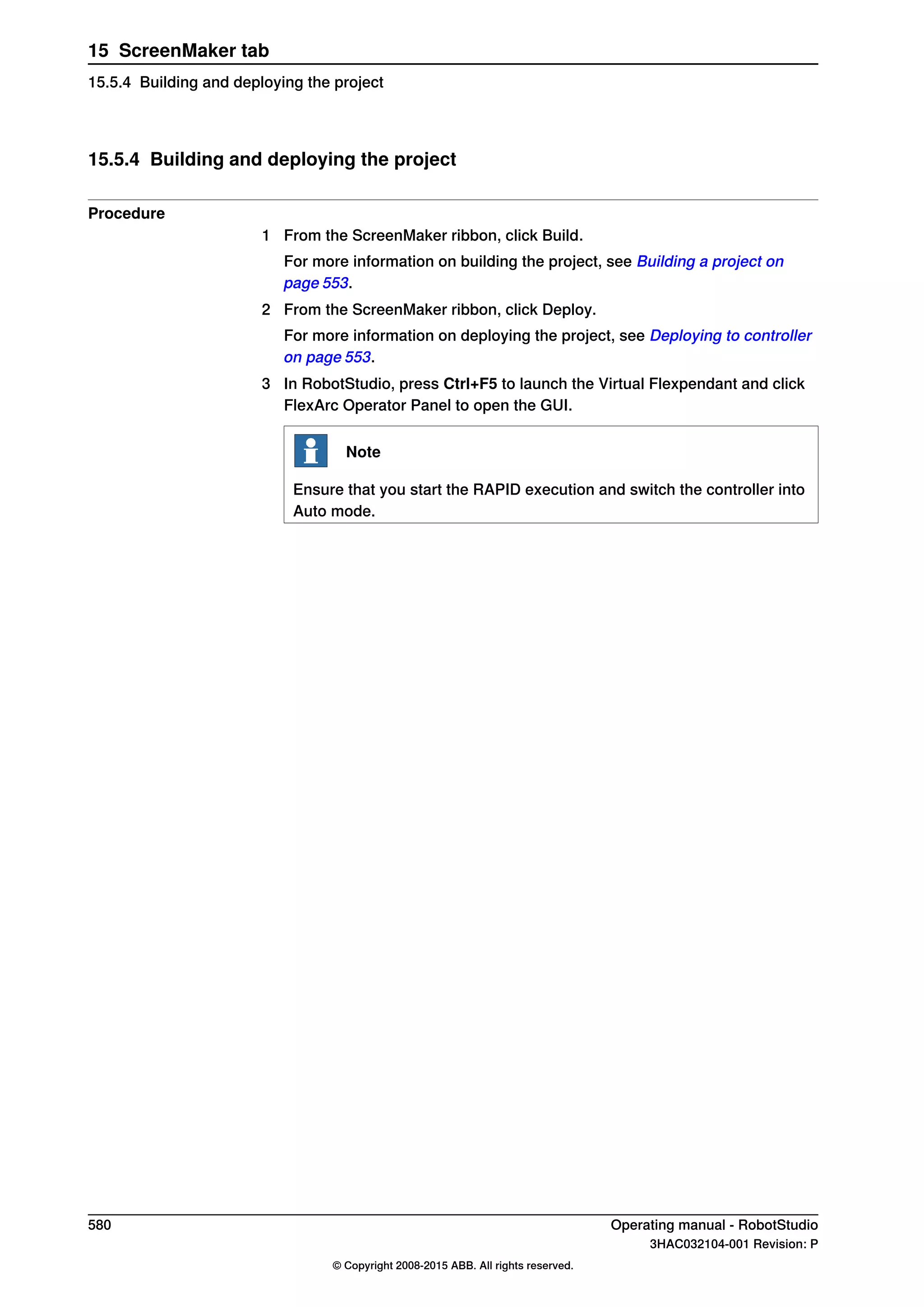
Overview
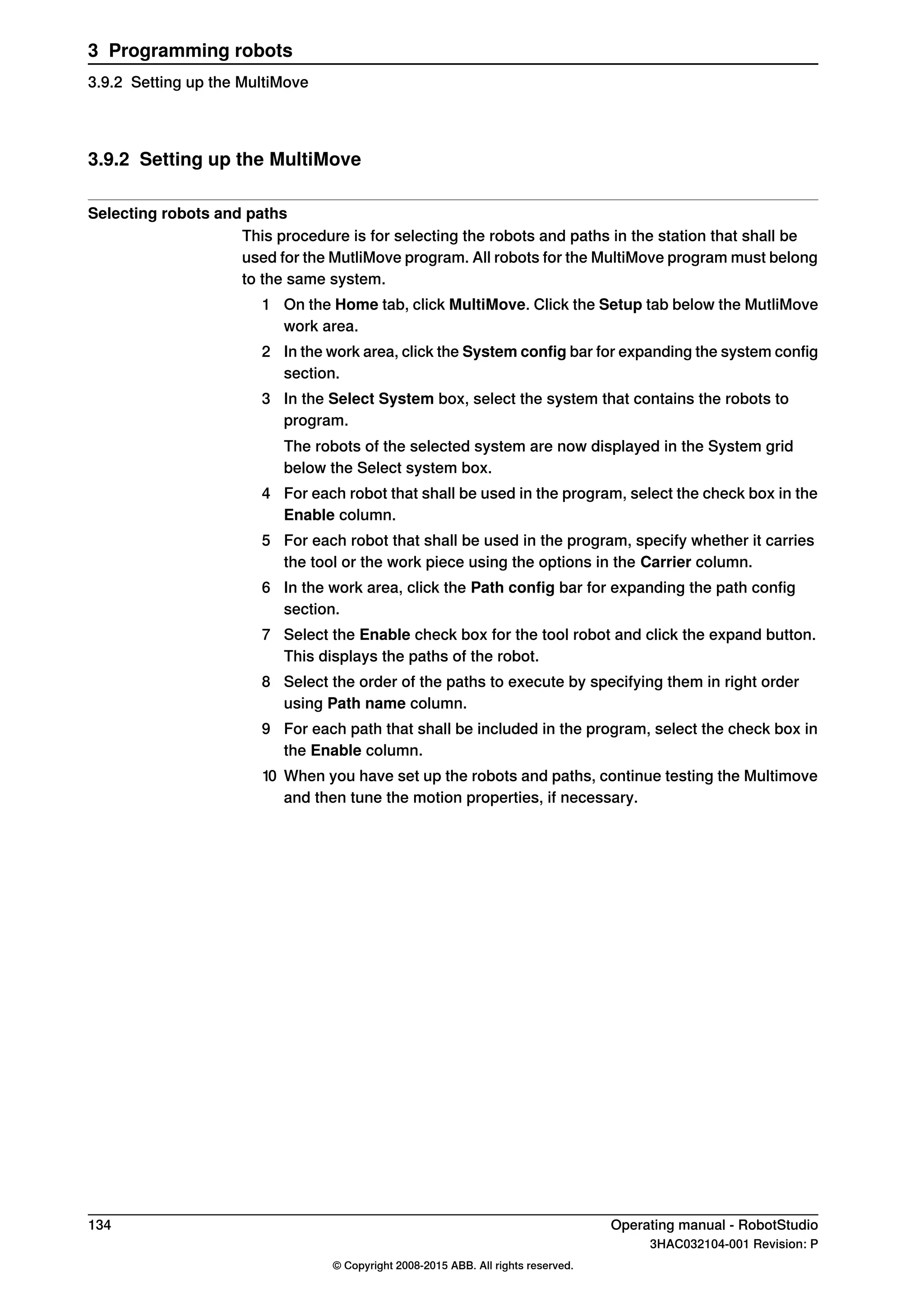
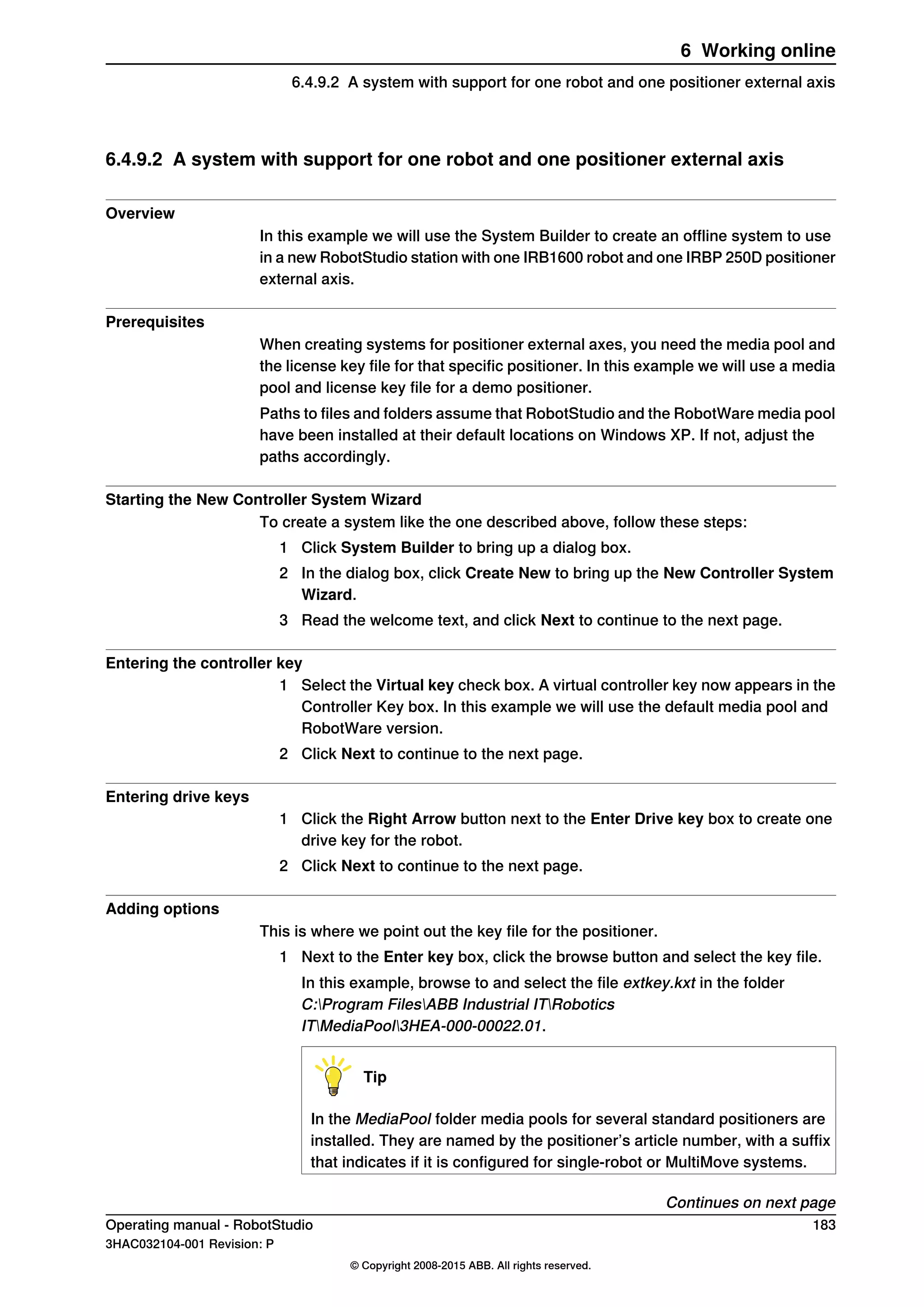
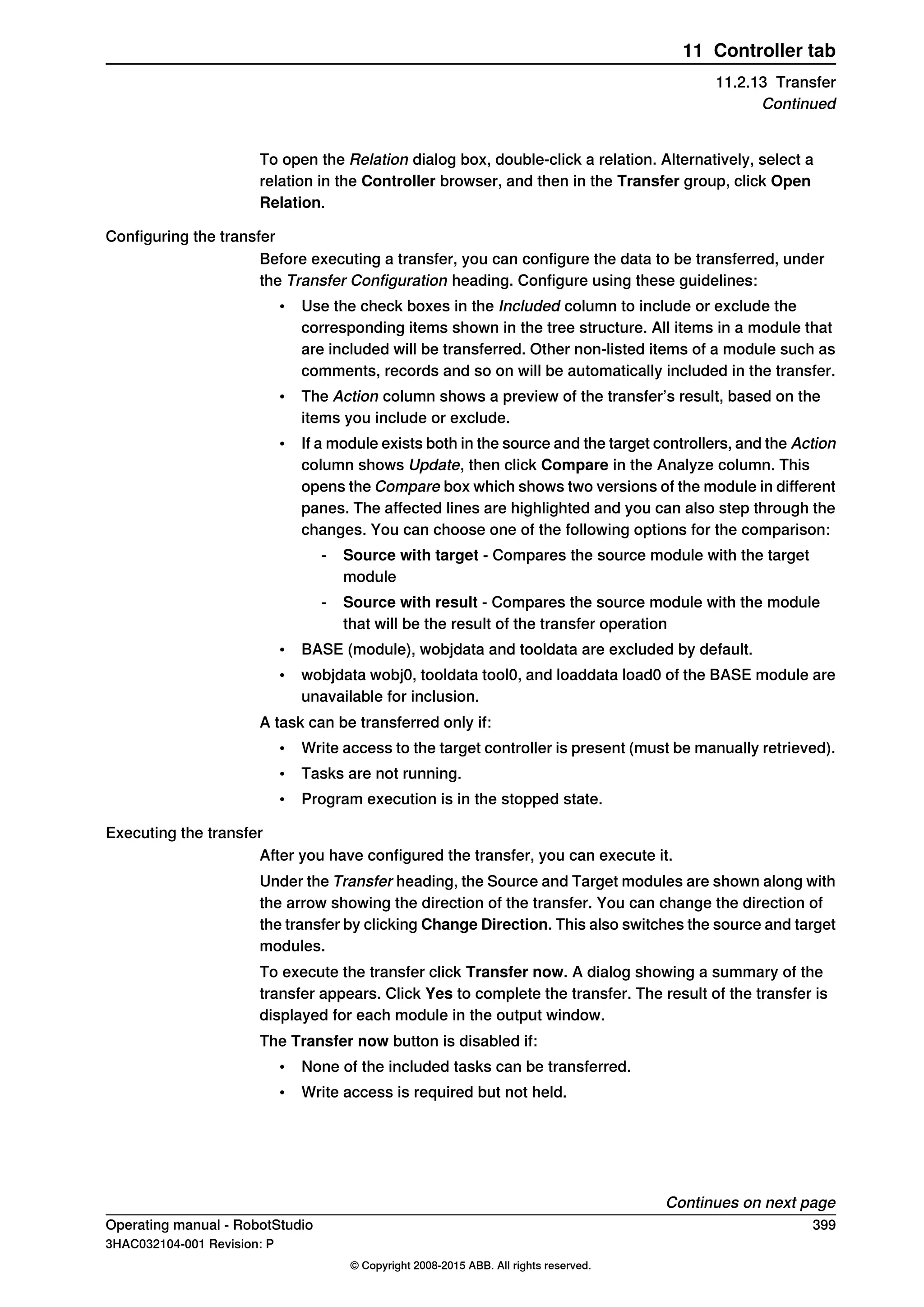
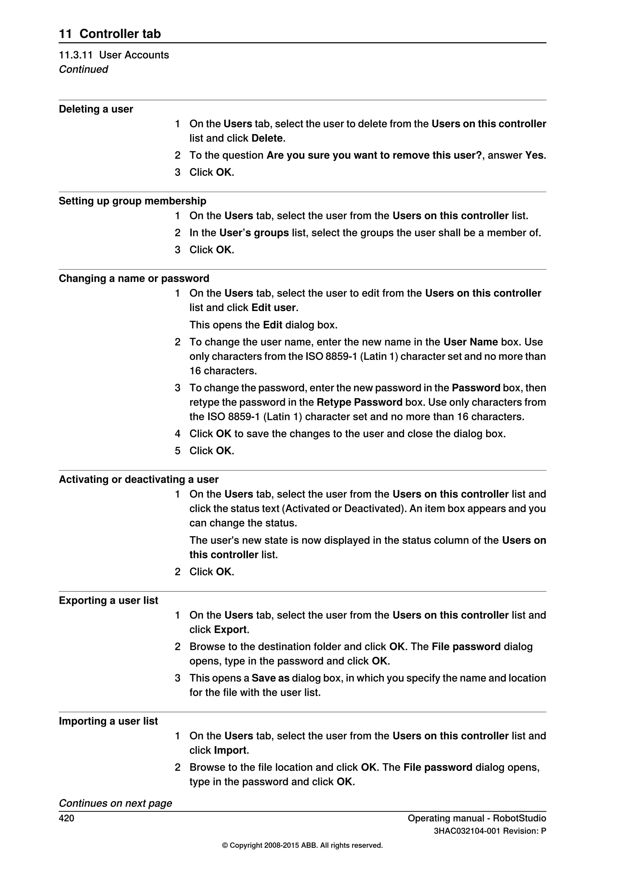
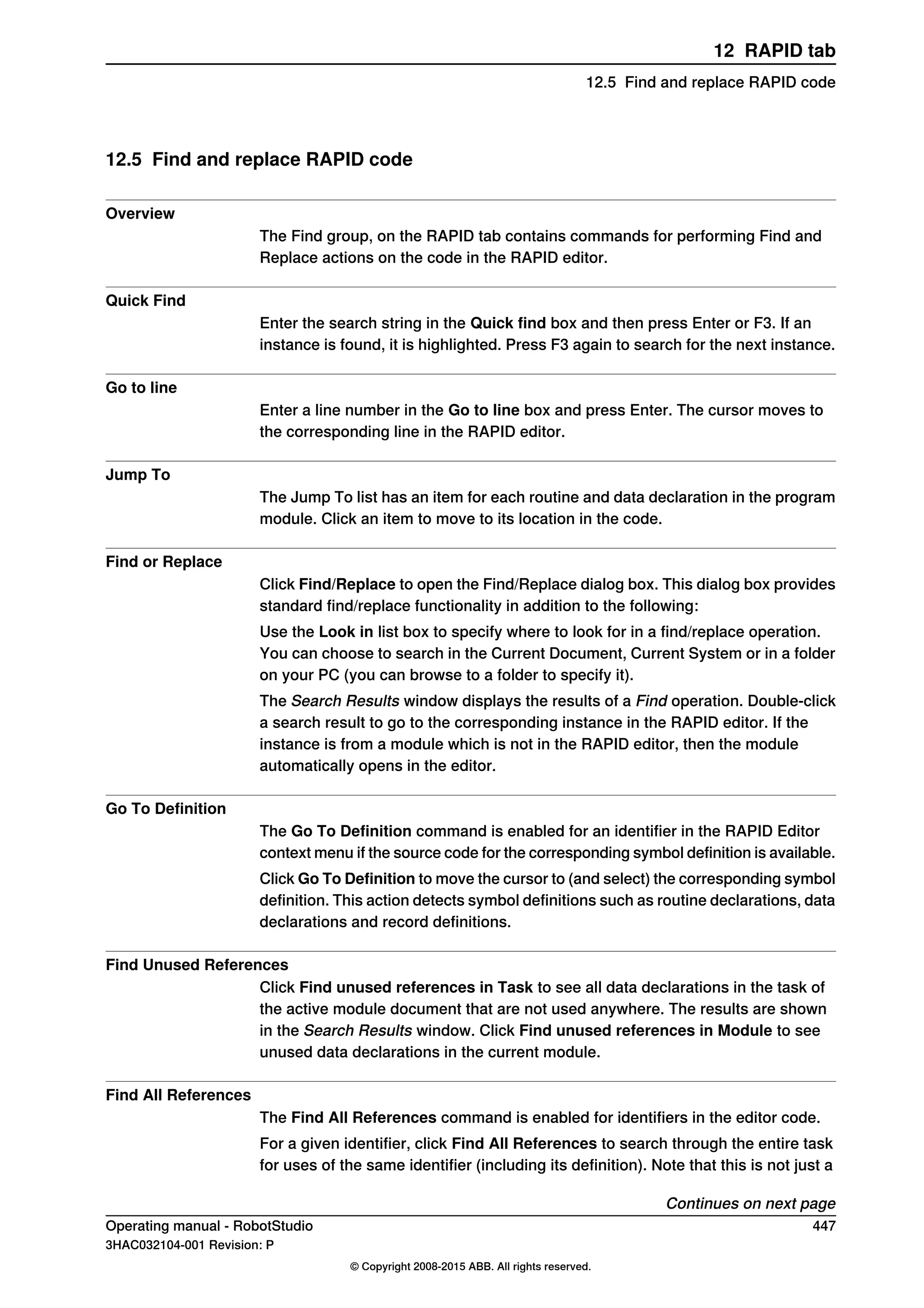
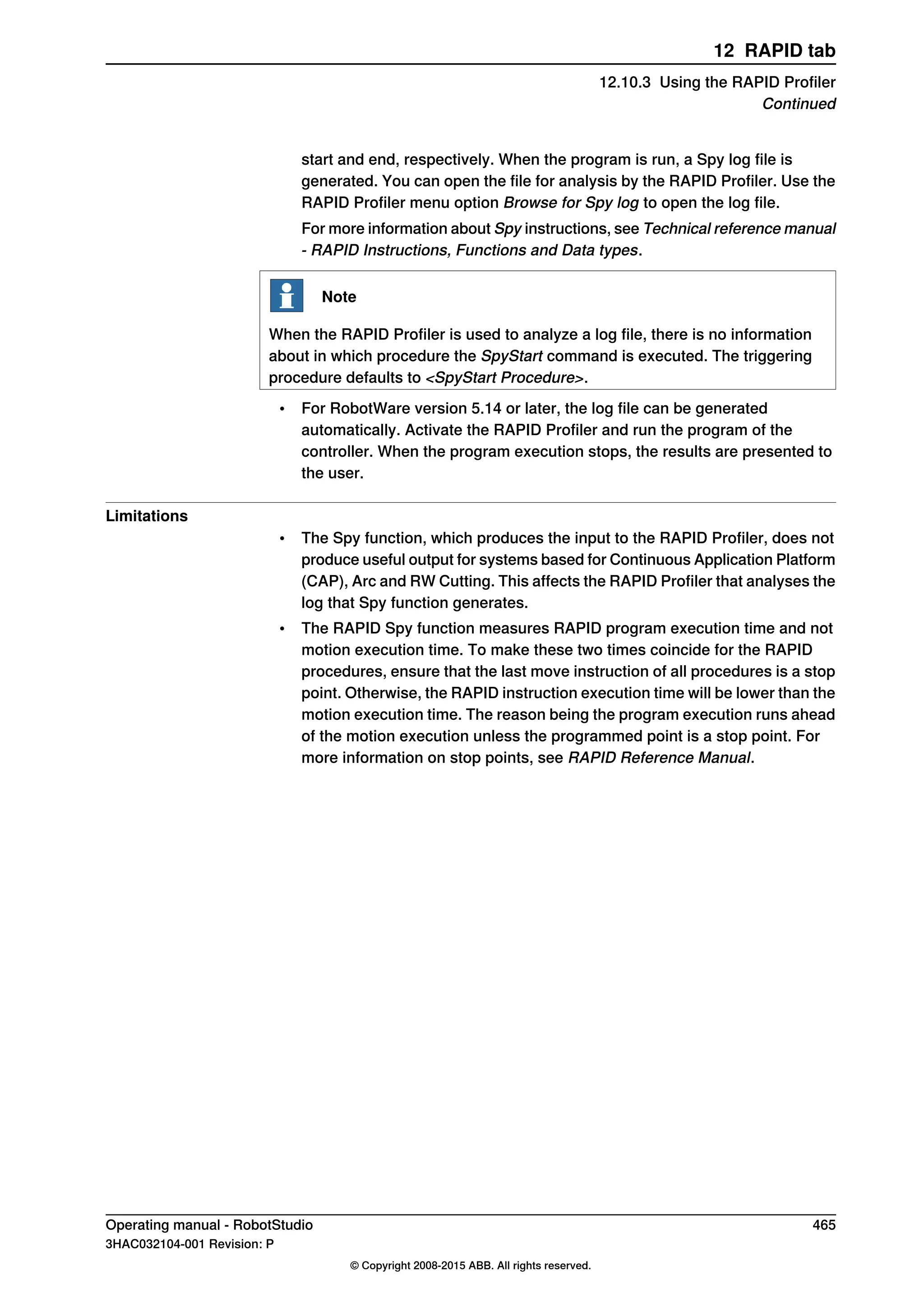
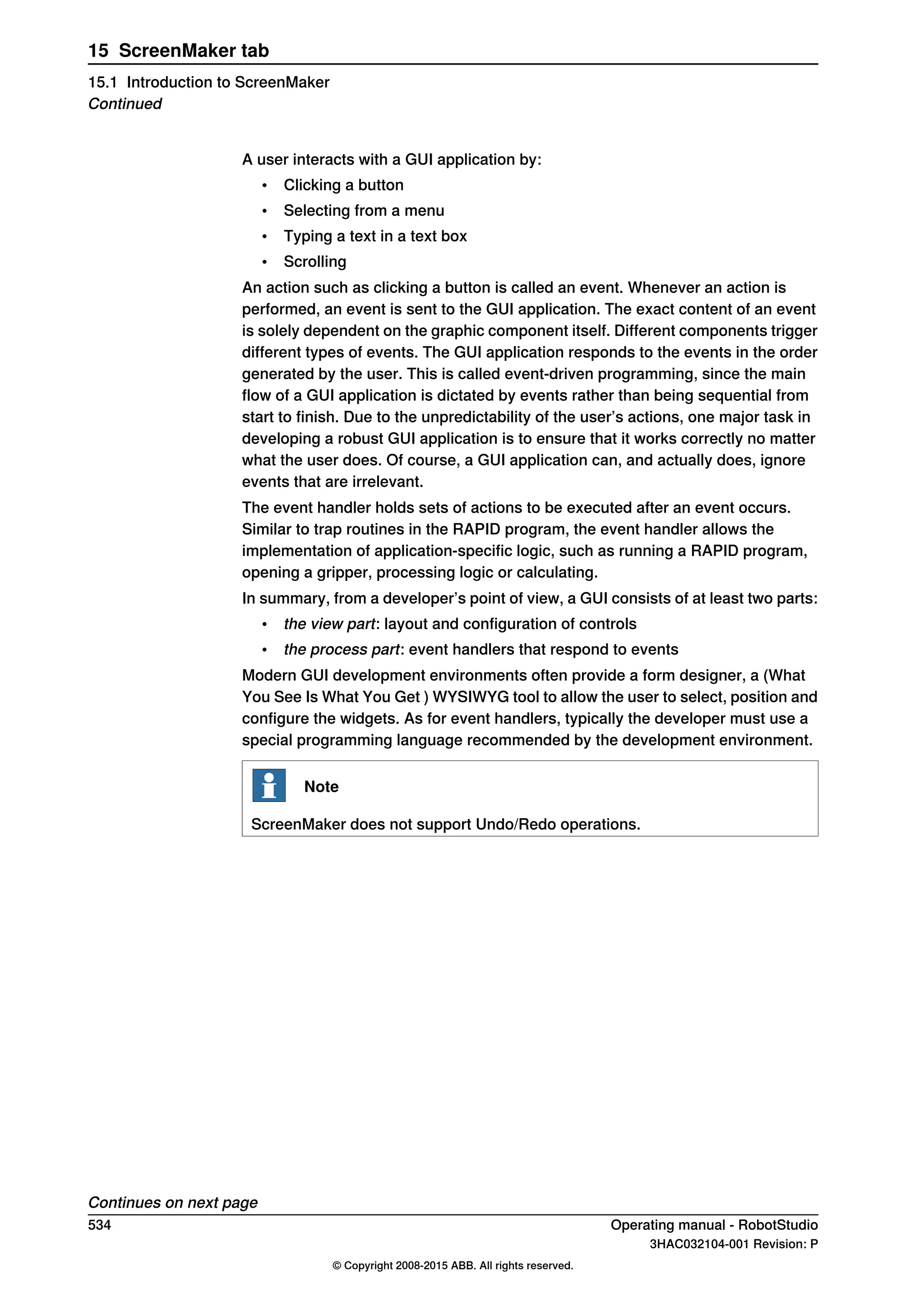
Smart Component is a RobotStudio object (with or without a 3D graphical
representation) that has the behavior which can be implemented by code-behind
and/or aggregation of other Smart Components.
Terminology
The following table describes the different terminologies that you come across
when working with Smart Component.
DefinitionTerm
A .NET class associated with a Smart Component that can
implement custom behavior by reacting to certain events, for
example simulation time steps and changes in property values.
Code behind
An object attached to a Smart Component that has value, type
and certain other characteristics. The property value is used
by code behind to control the behavior of the Smart Component.
[Dynamic] property
Connects the value of one property to the value of another
property.
[Property] binding
Key-value pairs that contain additional information about a
dynamic property, for example value constraints.
[Property] attributes
An object attached to a Smart Component that has a value and
a direction (input/output), analogous to I/O signals on a robot
controller. The signal value is used by code behind to control
the behavior of the Smart Component.
[I/O] signal
Connects the value of one signal to the value of a different
signal.
[I/O] connection
The process of connecting several Smart Components using
bindings and/or connections in order to implement a more
complex behavior.
Aggregation
Data object contained in a Smart Component. Uses include
code behind assembly and localized resources.
Asset
284 Operating manual - RobotStudio
3HAC032104-001 Revision: P
© Copyright 2008-2015 ABB. All rights reserved.
9 Modeling tab
9.4.1 Smart Component](https://image.slidesharecdn.com/prog-150726124729-lva1-app6892/75/Prog-284-2048.jpg)


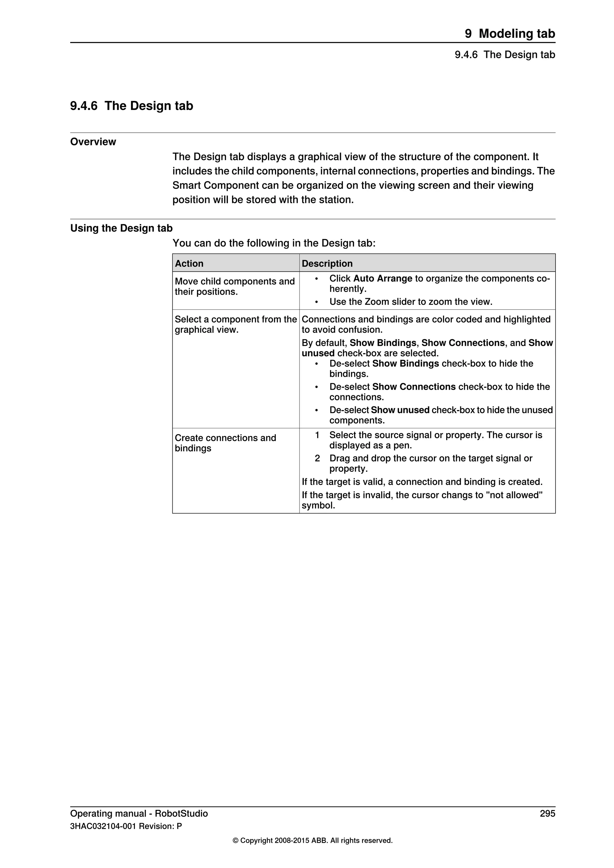

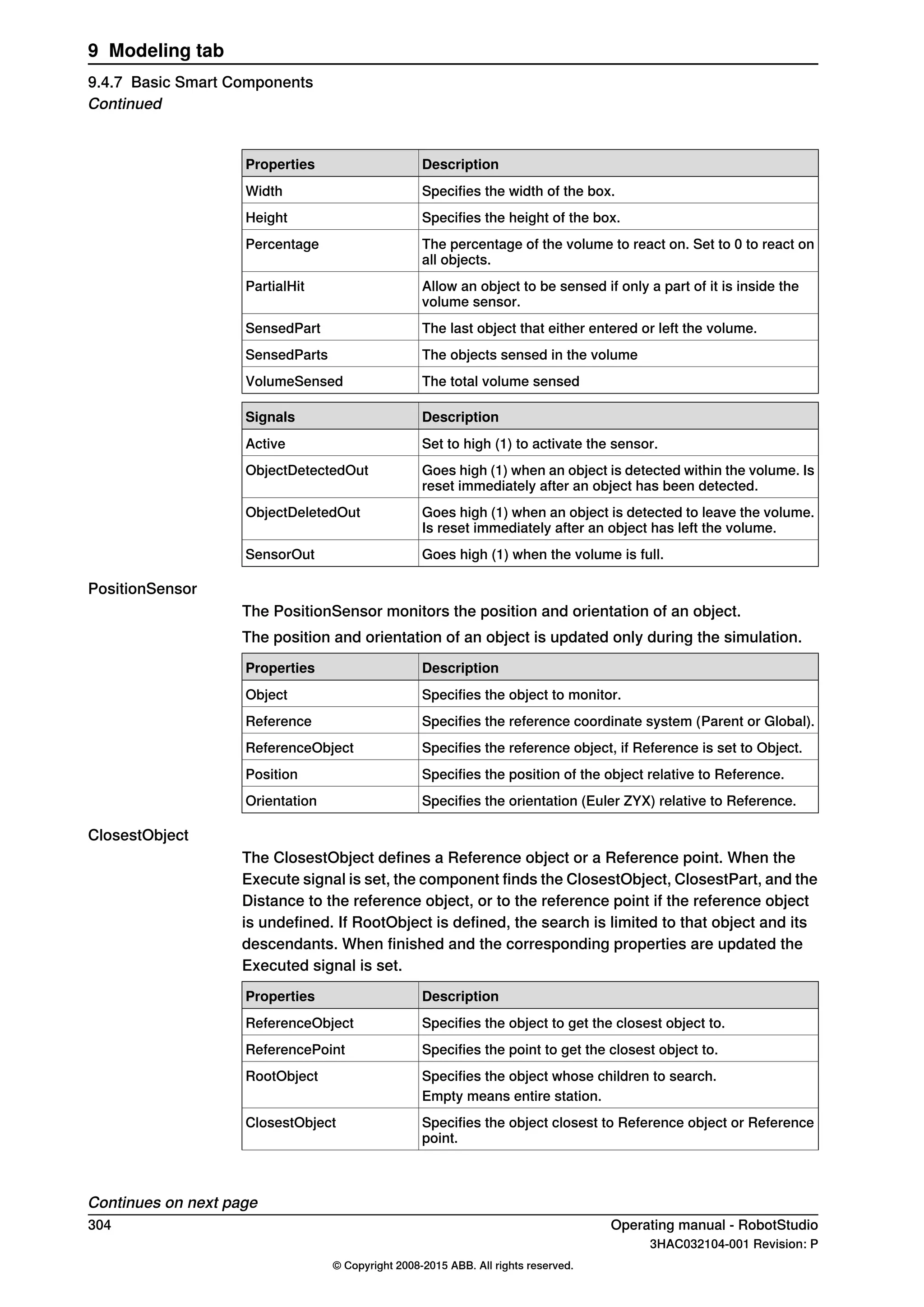

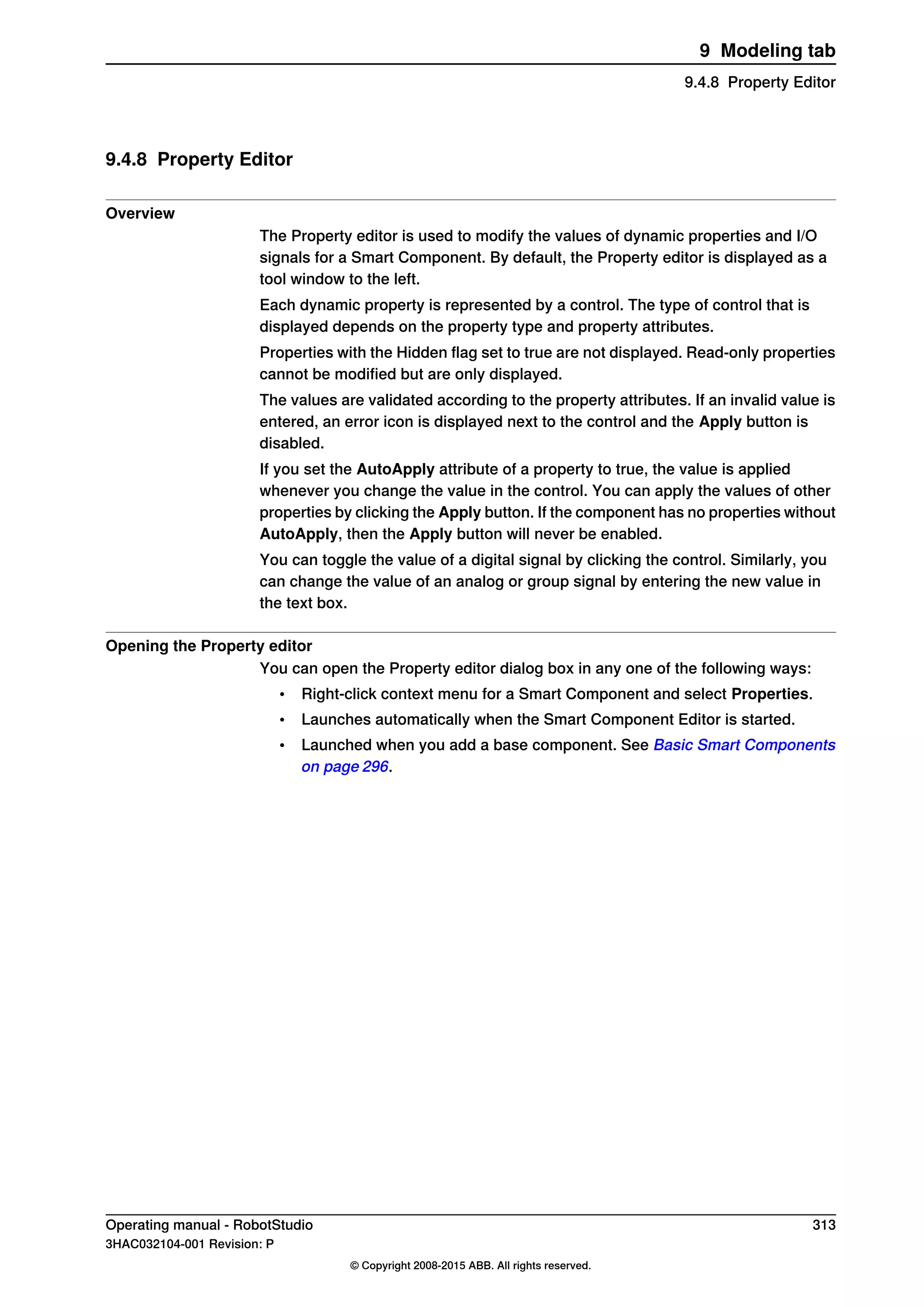


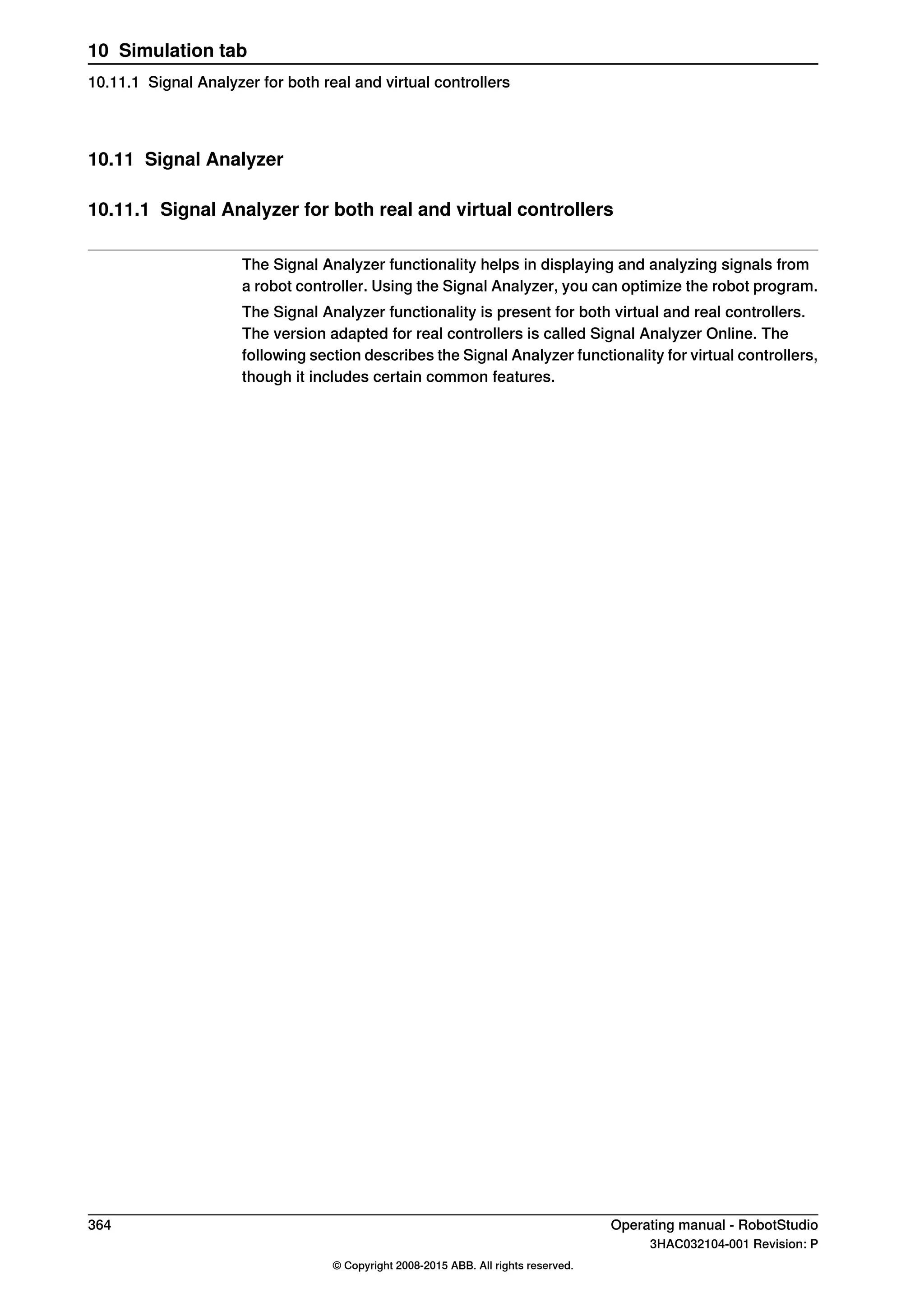


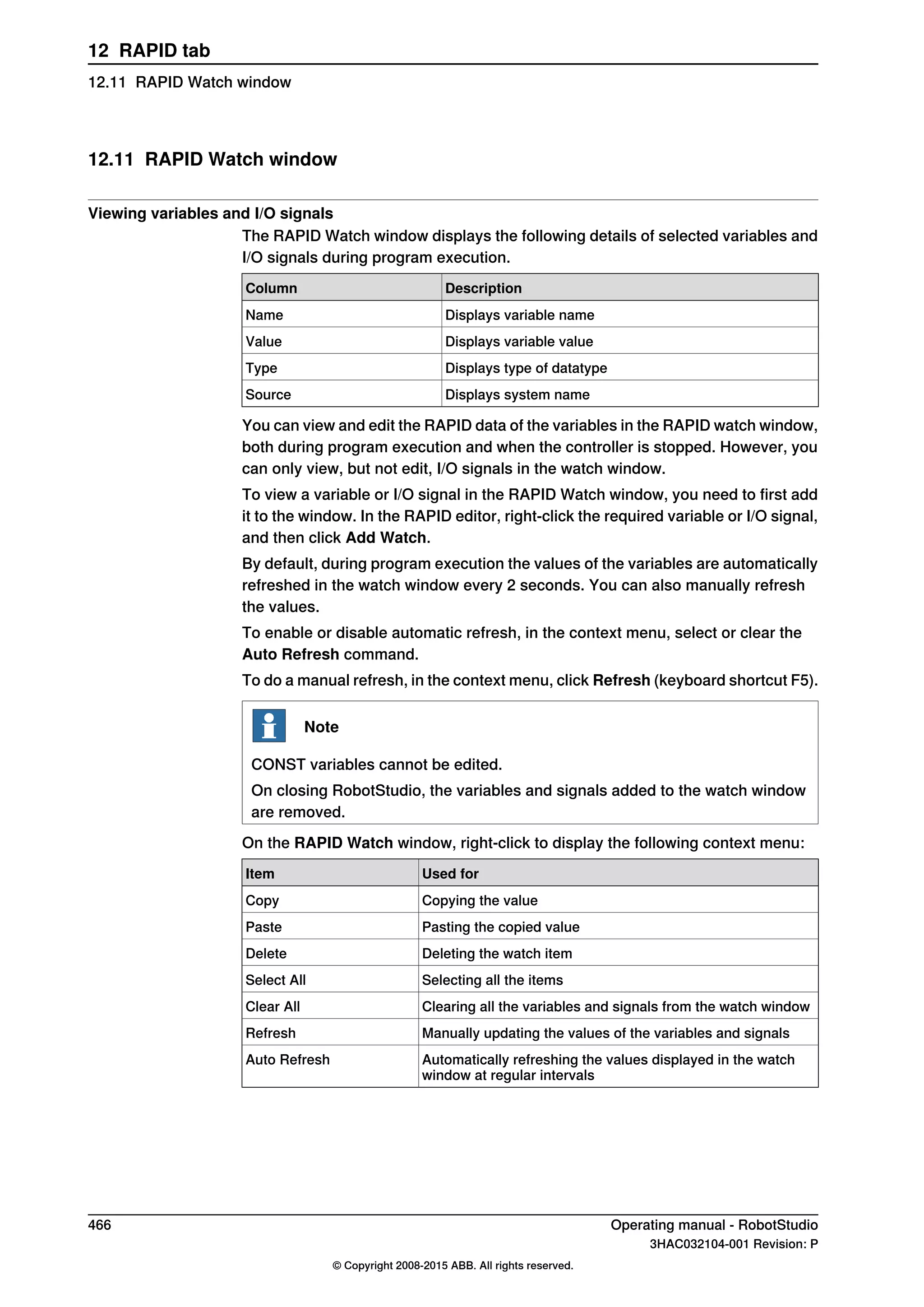


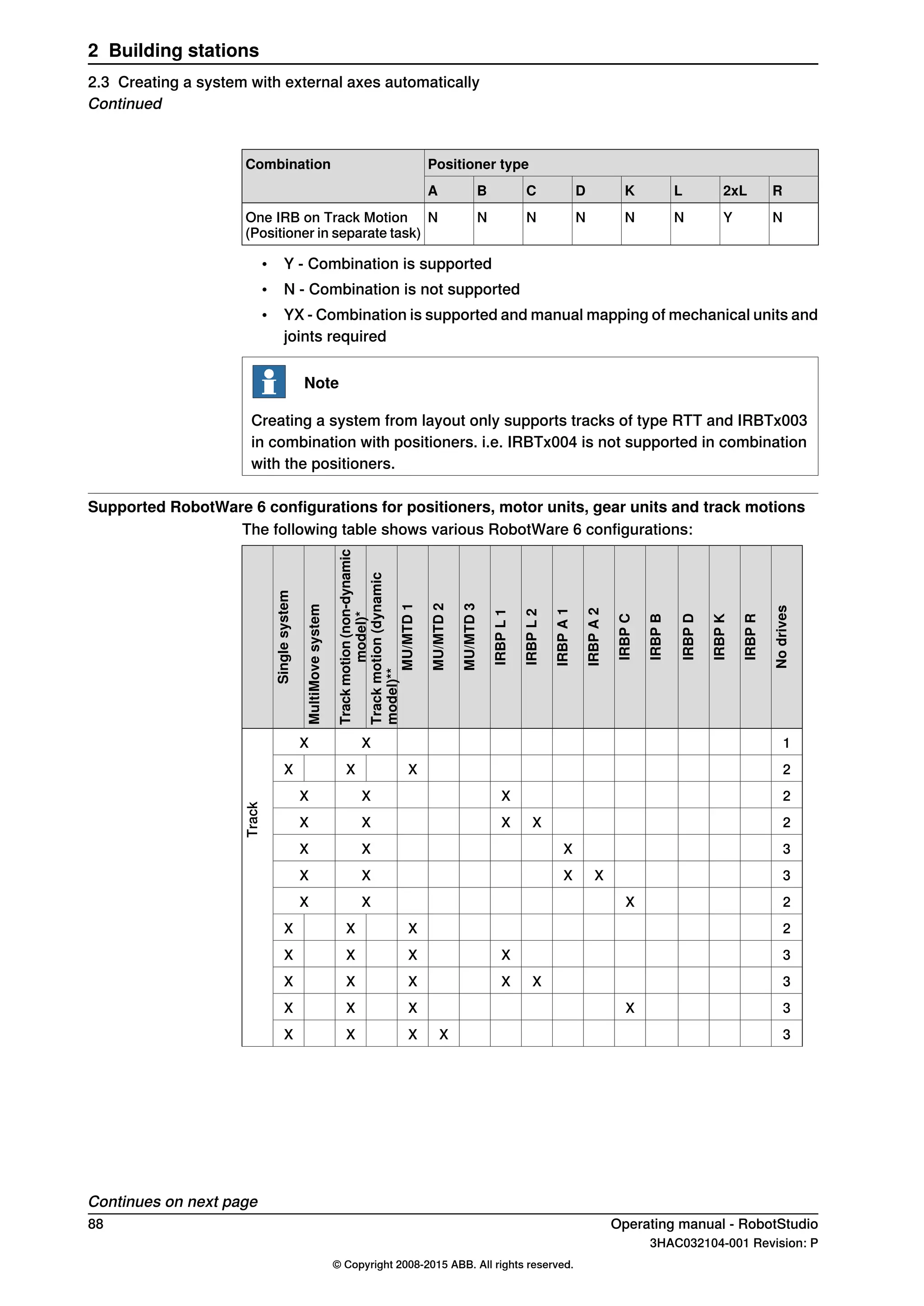
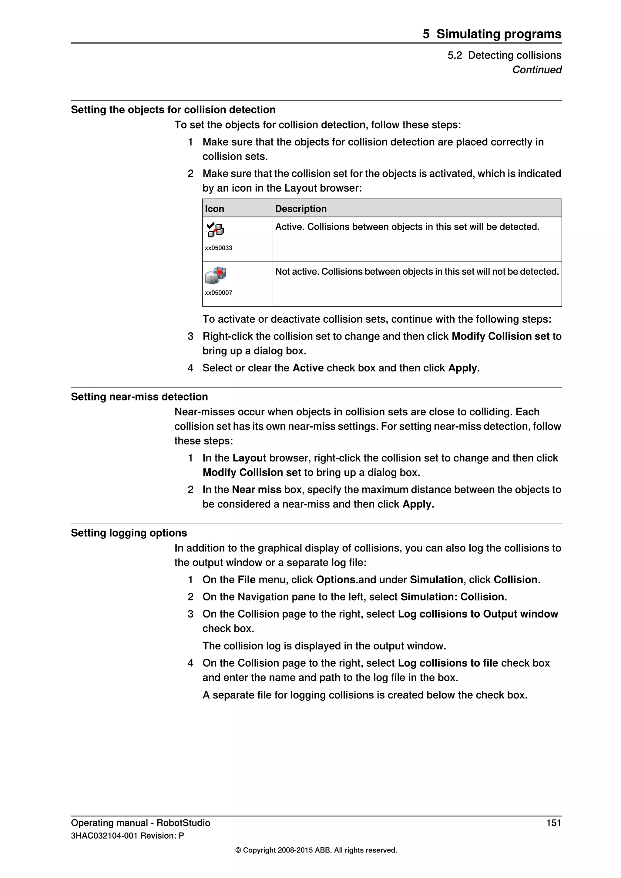
![bound variable. 0 and 1 for digital input. It is also possible to bind to RAPID variables
and have multiple states and values for the values in the RAPID variable.
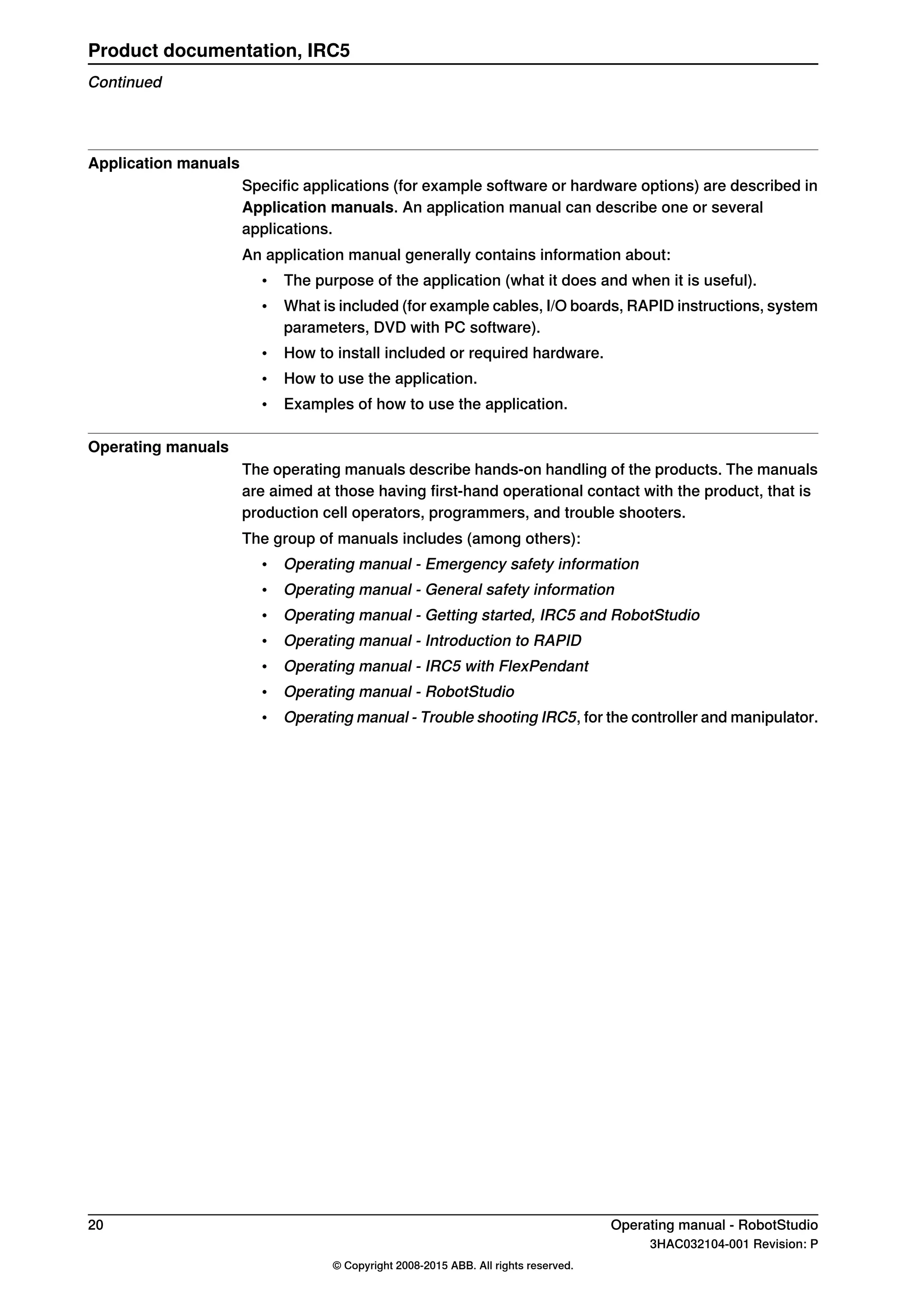
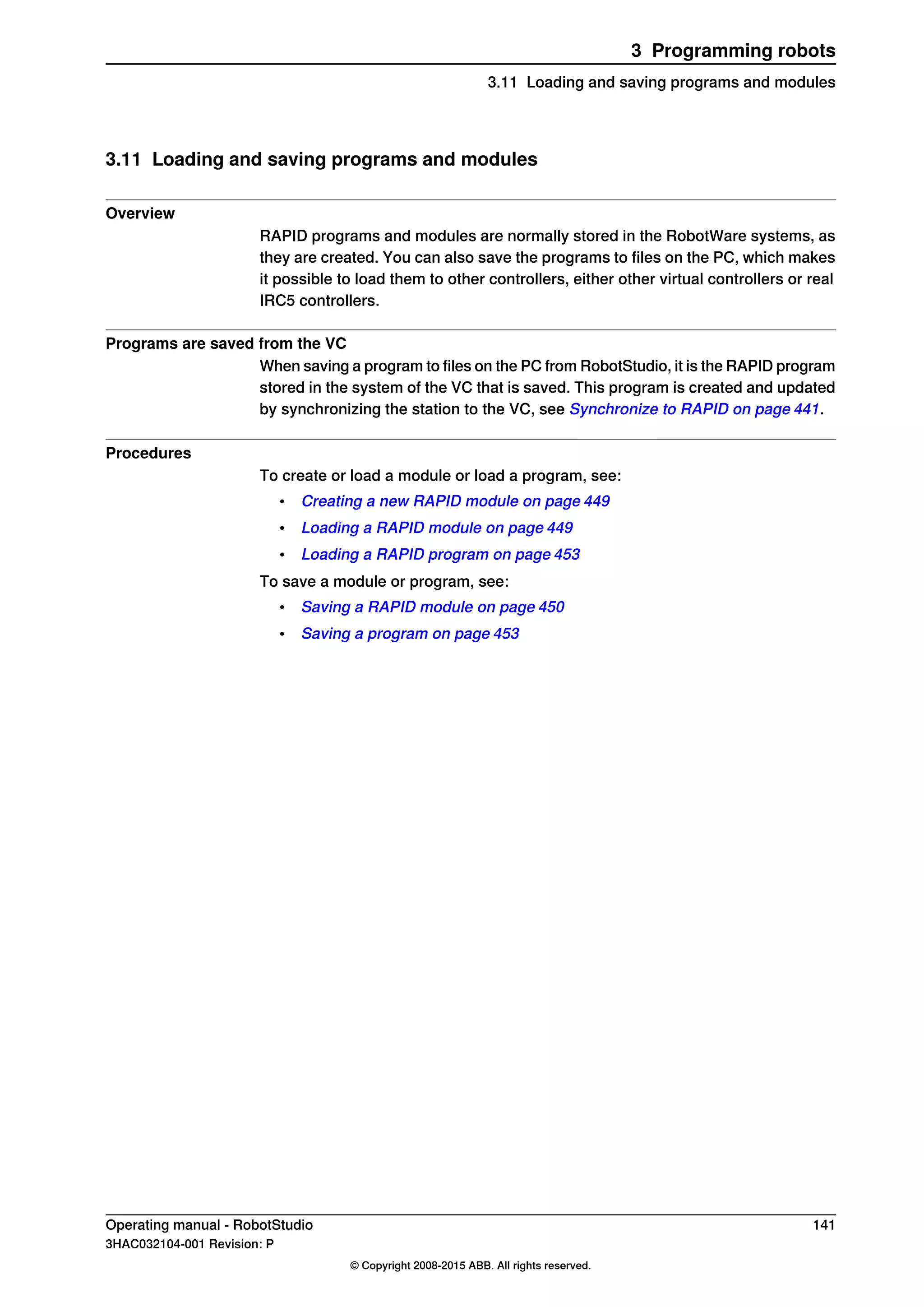
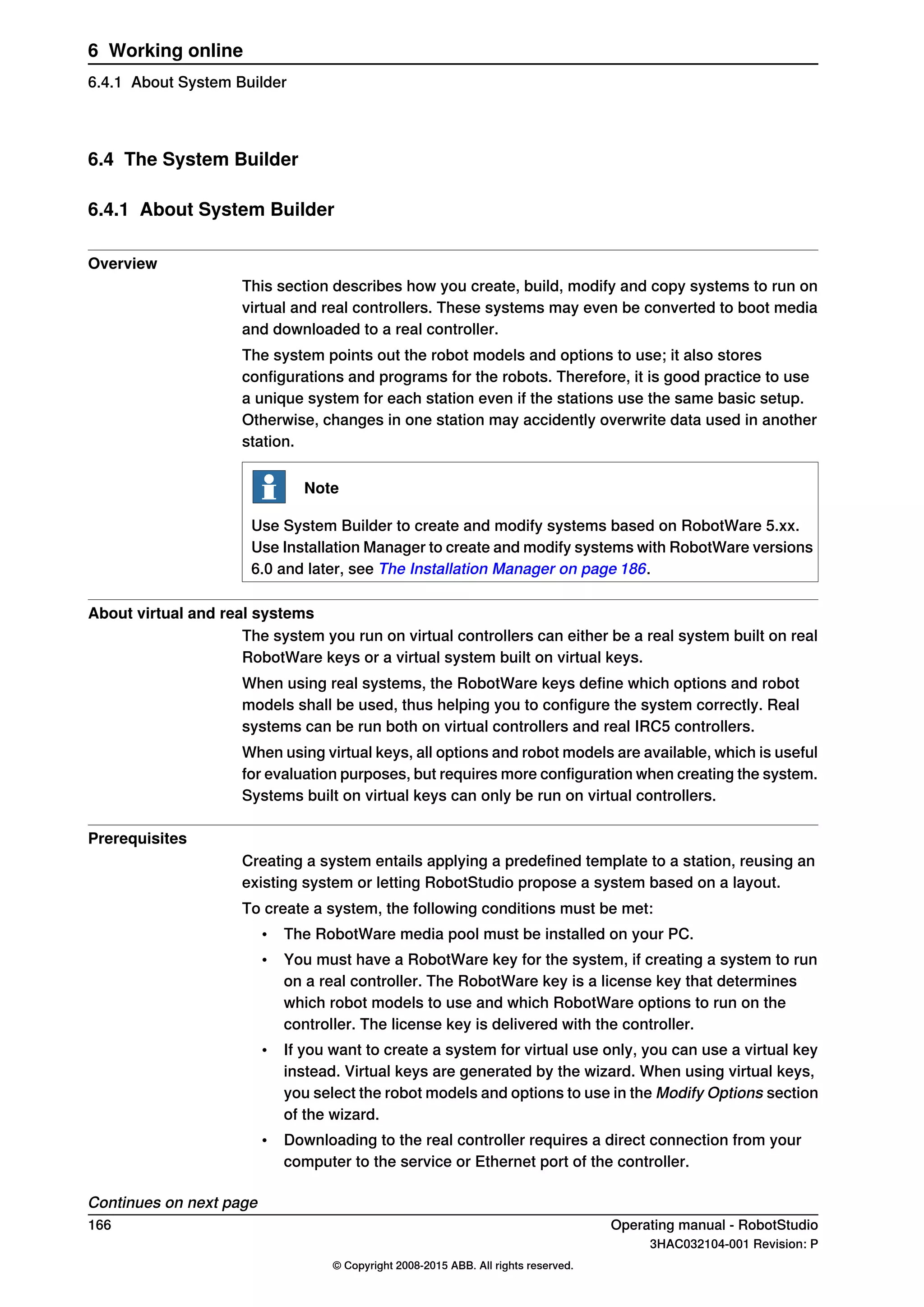
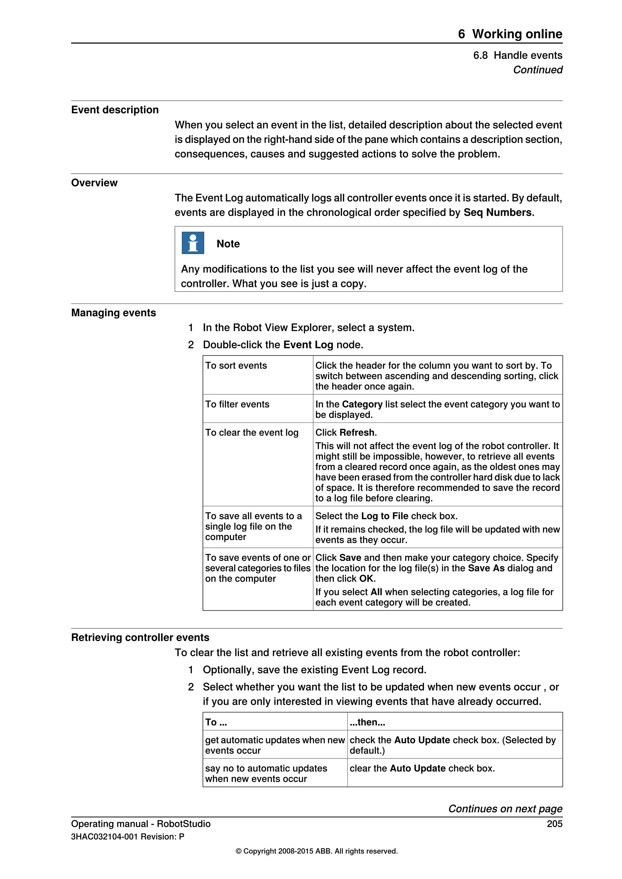
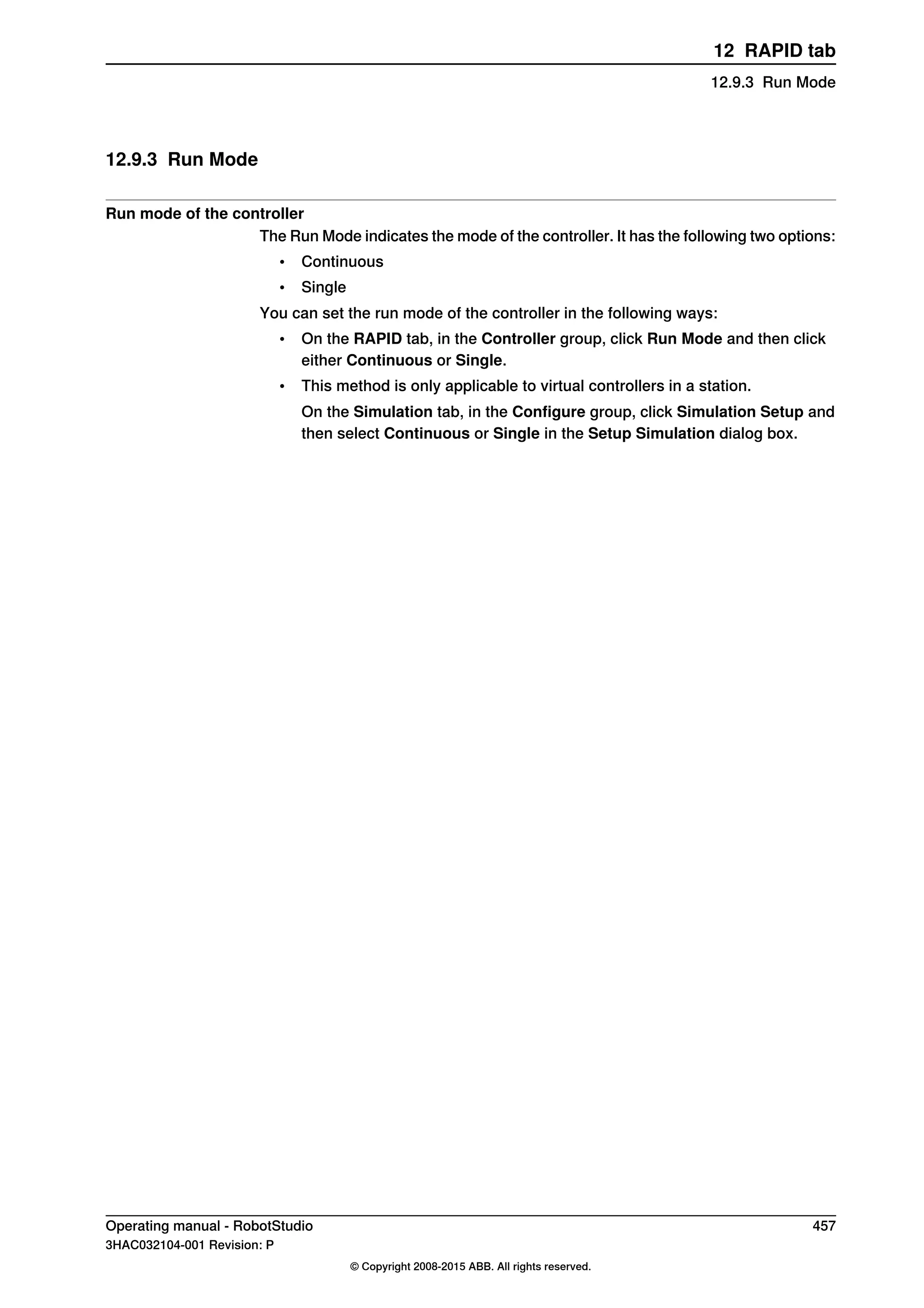
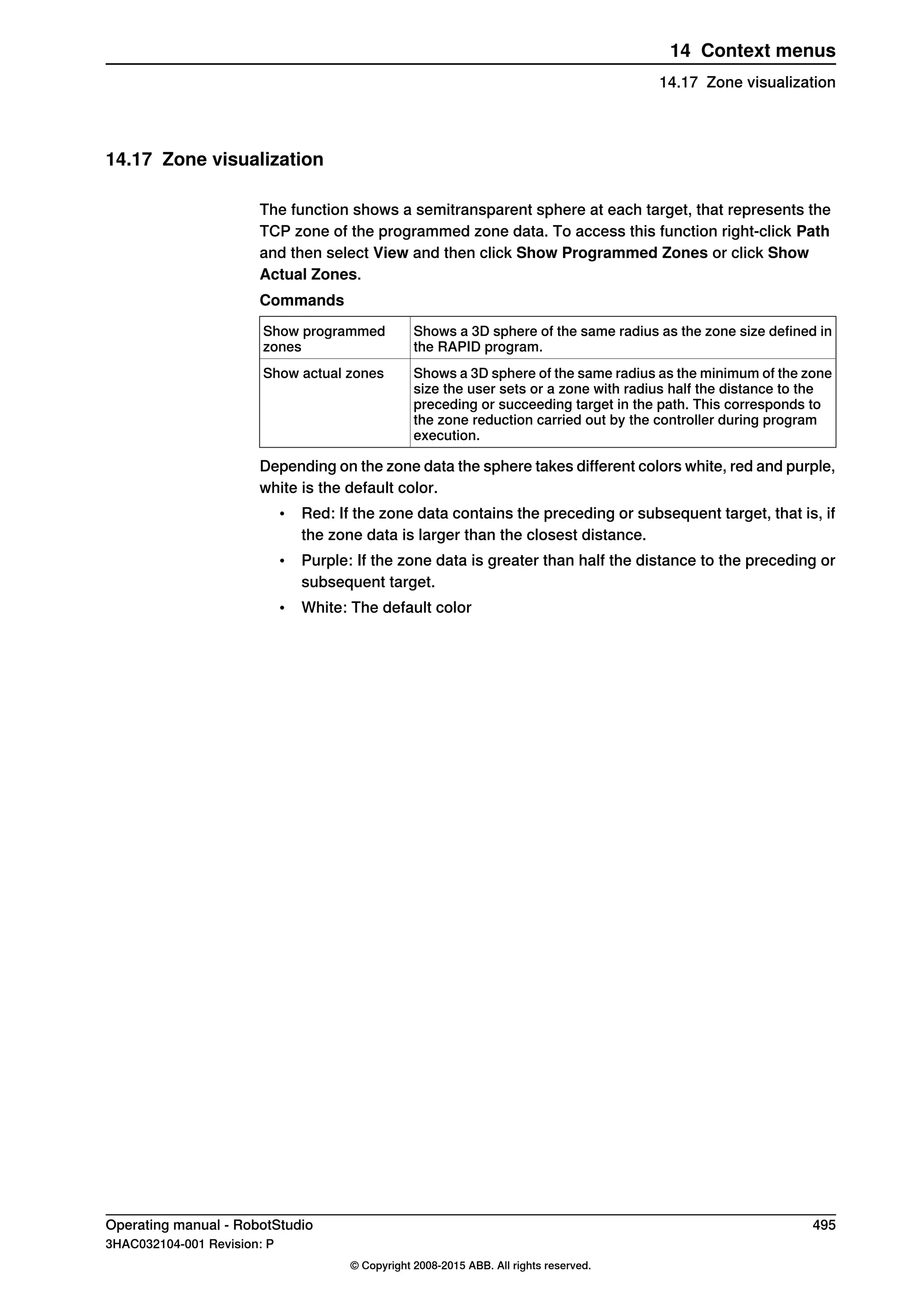
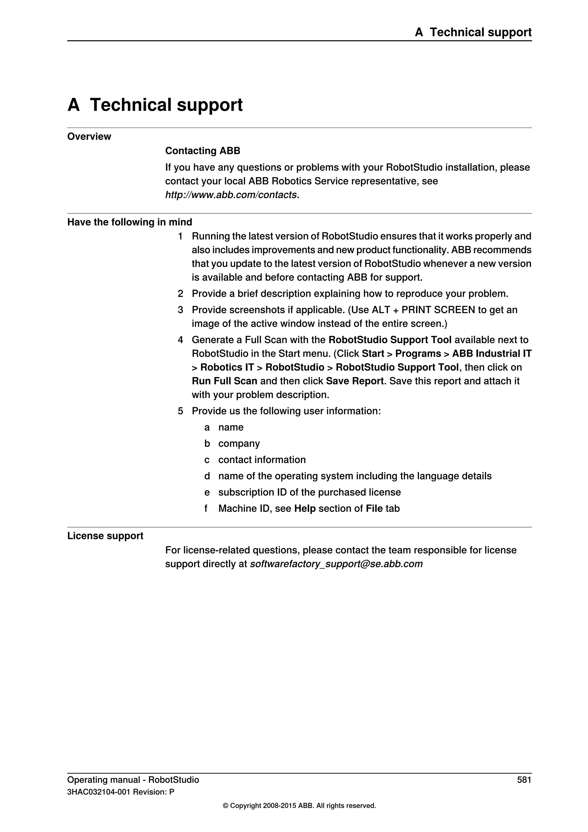
Set the SelectedStateValue property to bind to a controller object:
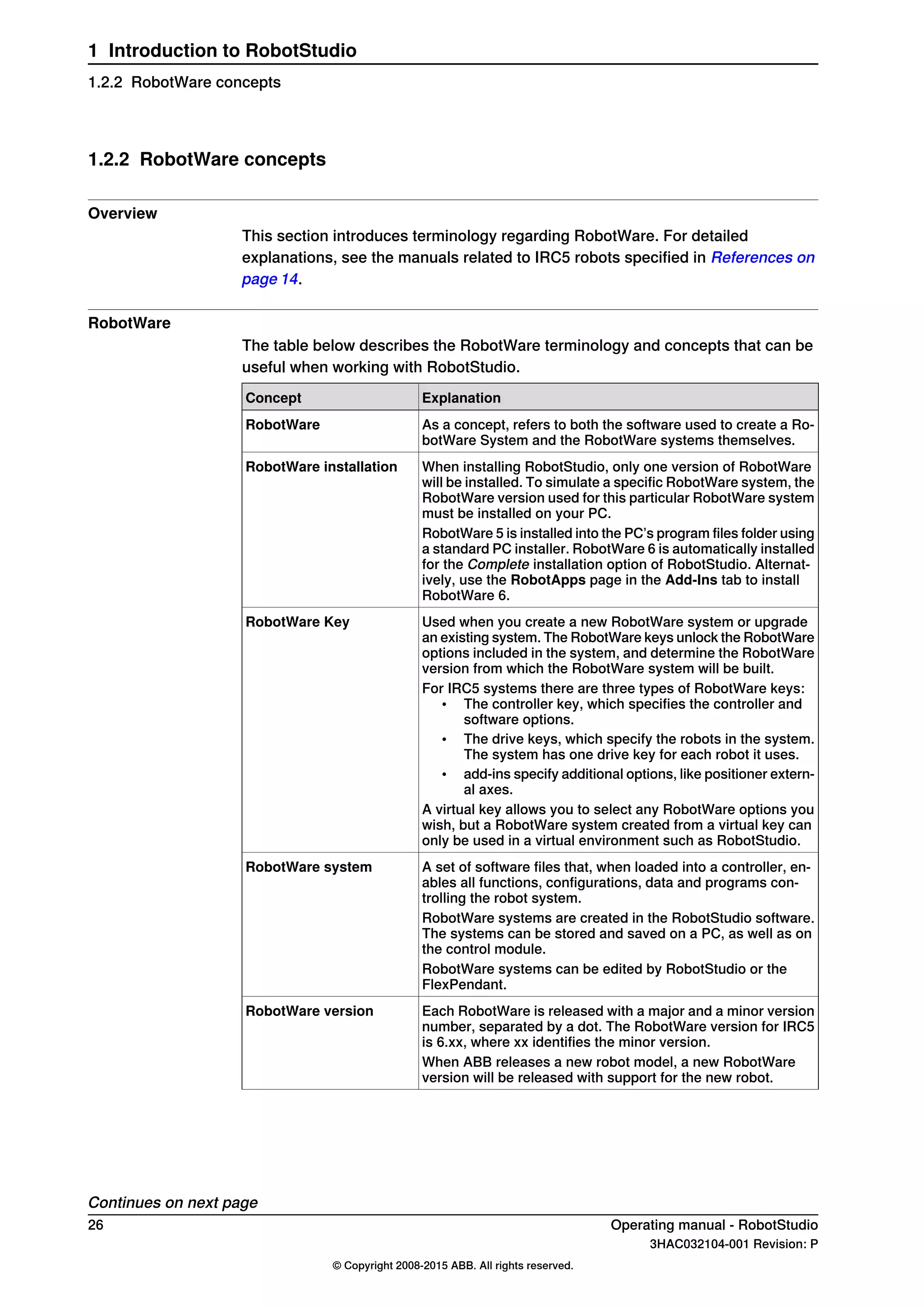
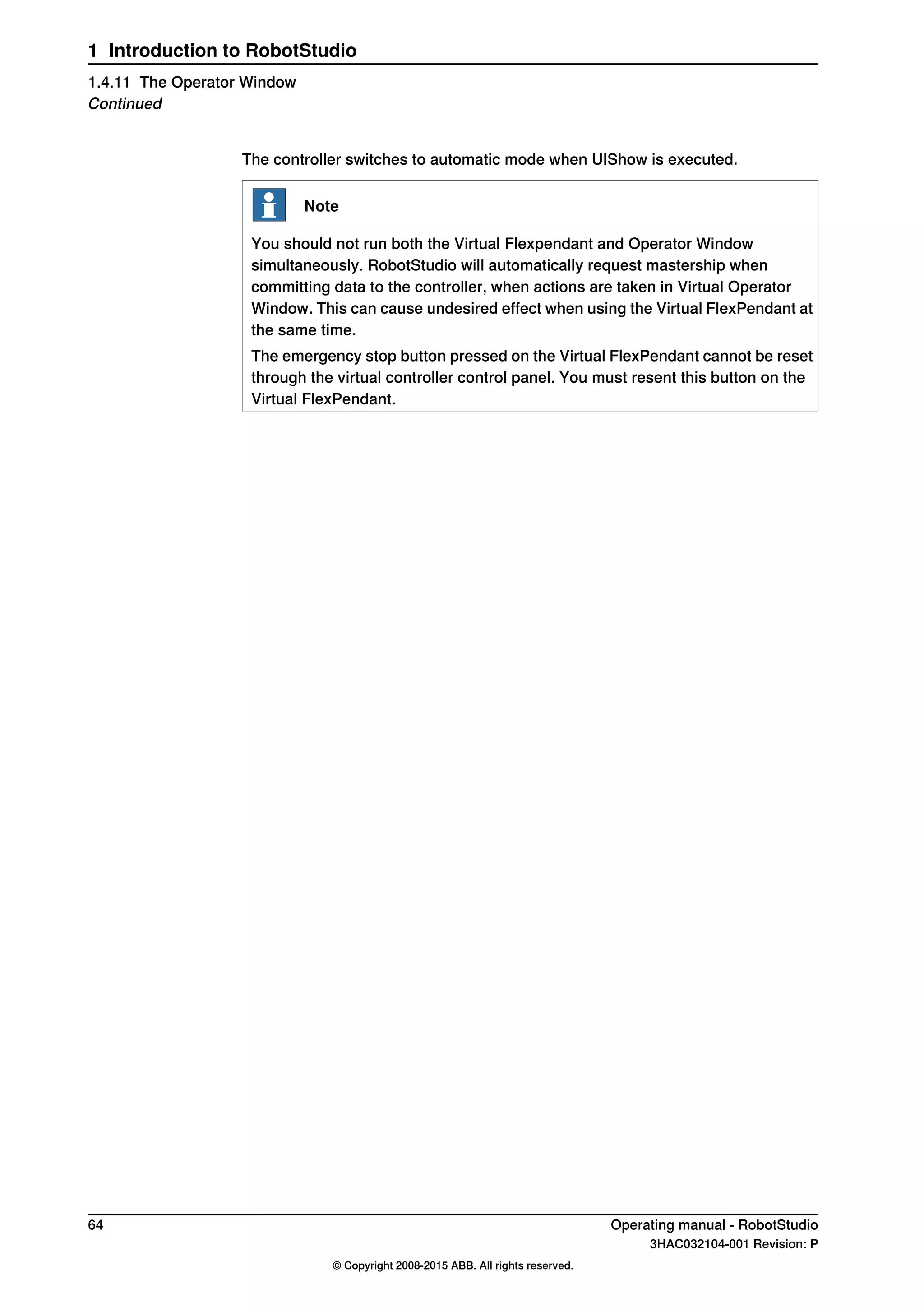
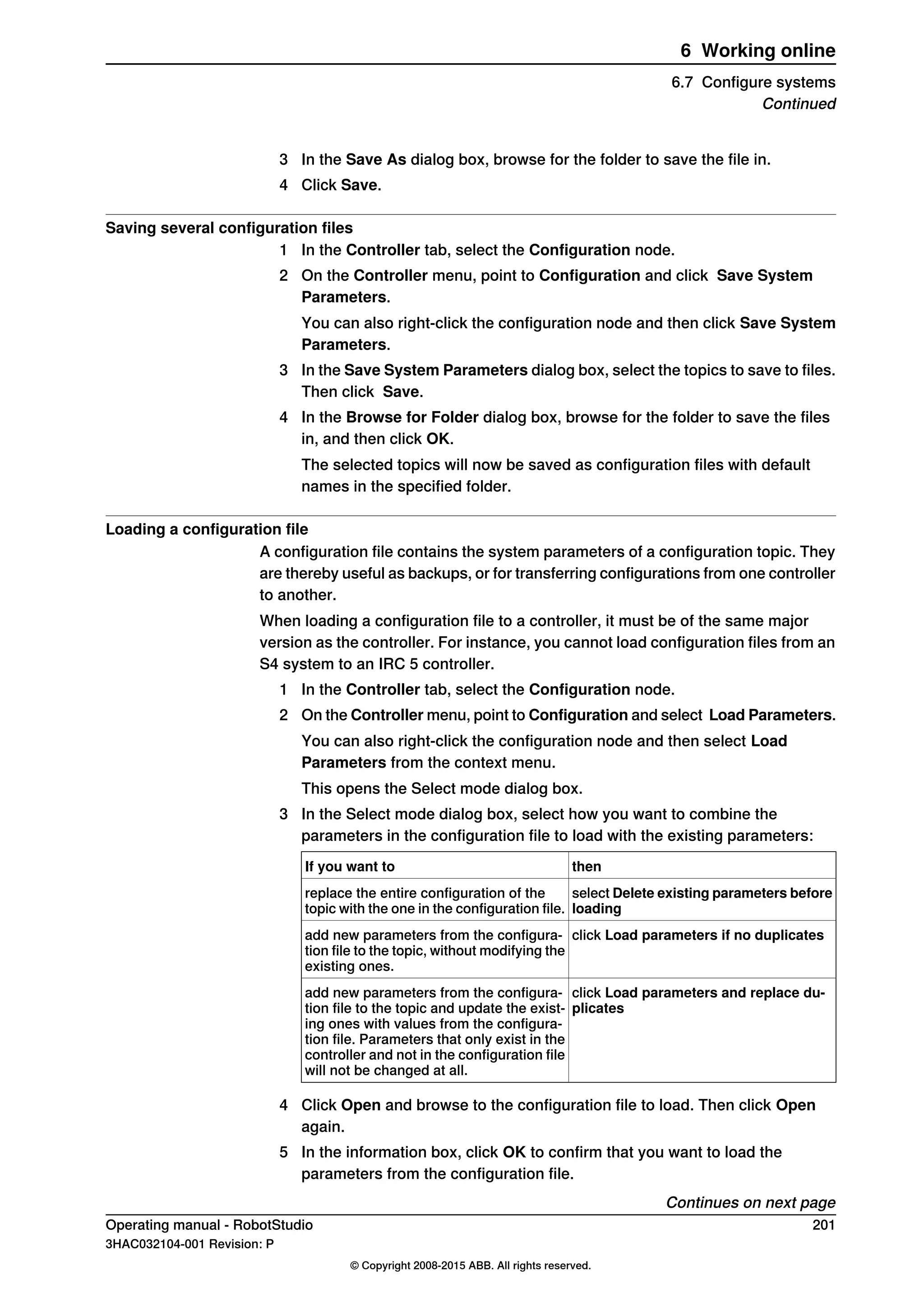
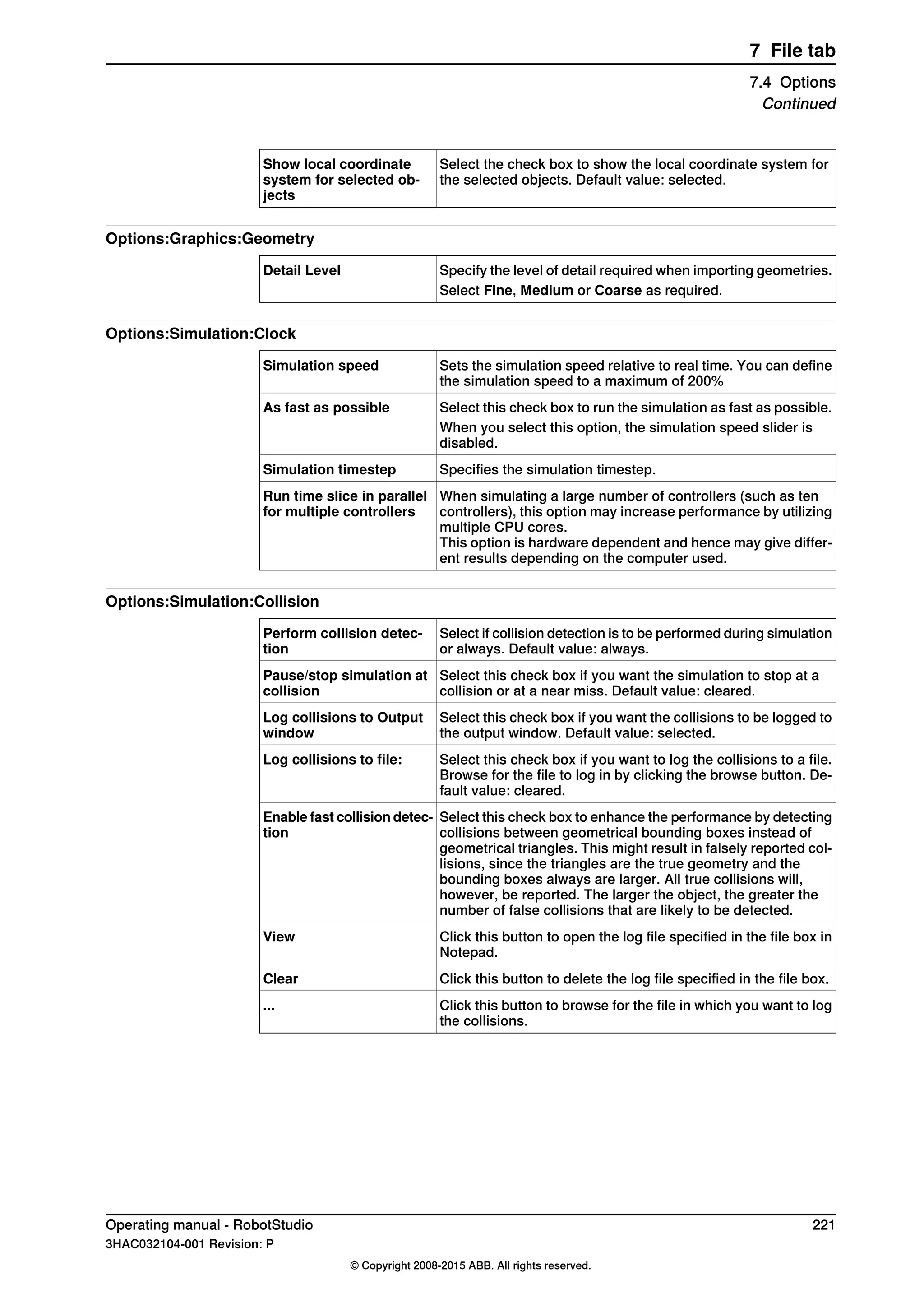
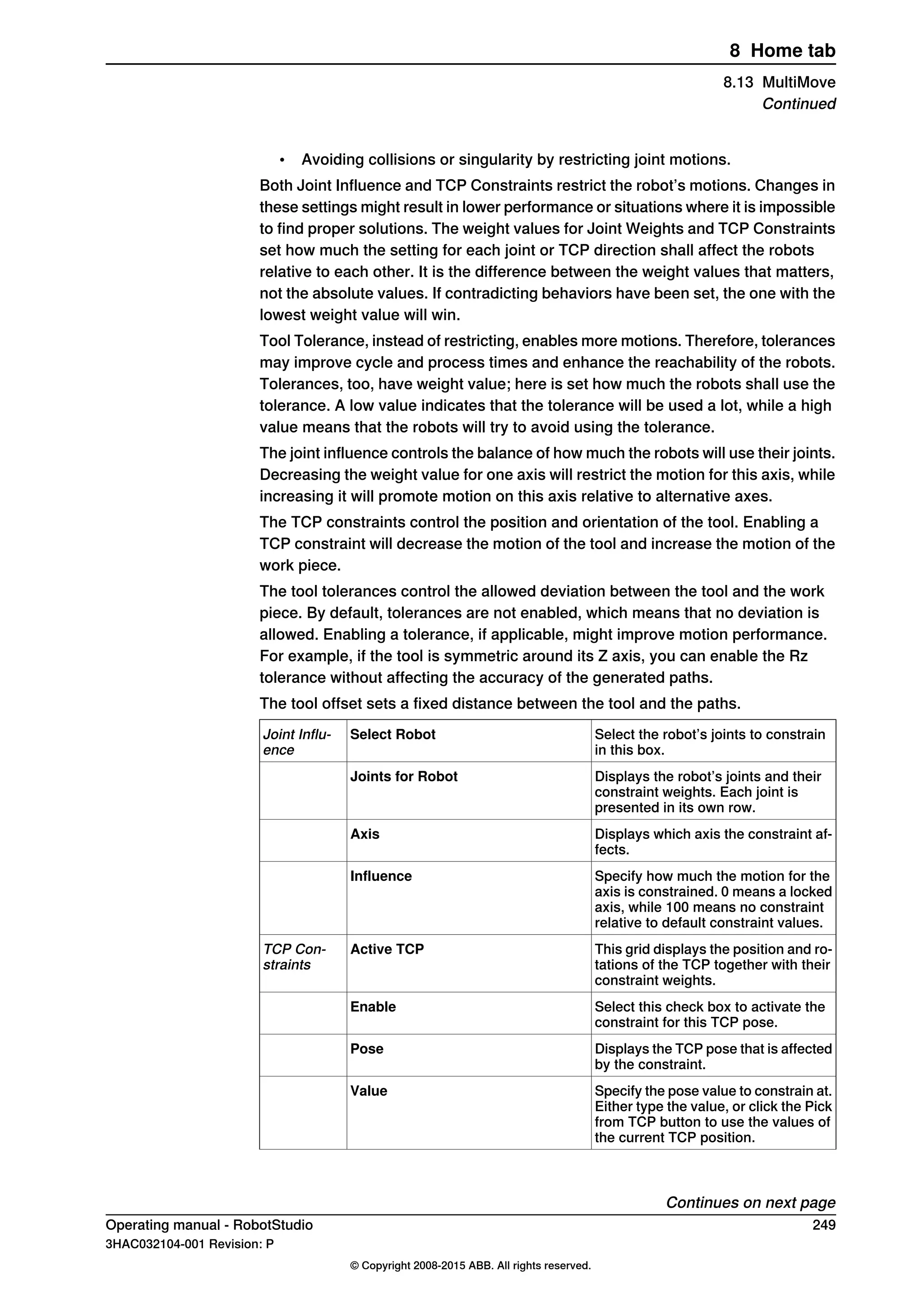
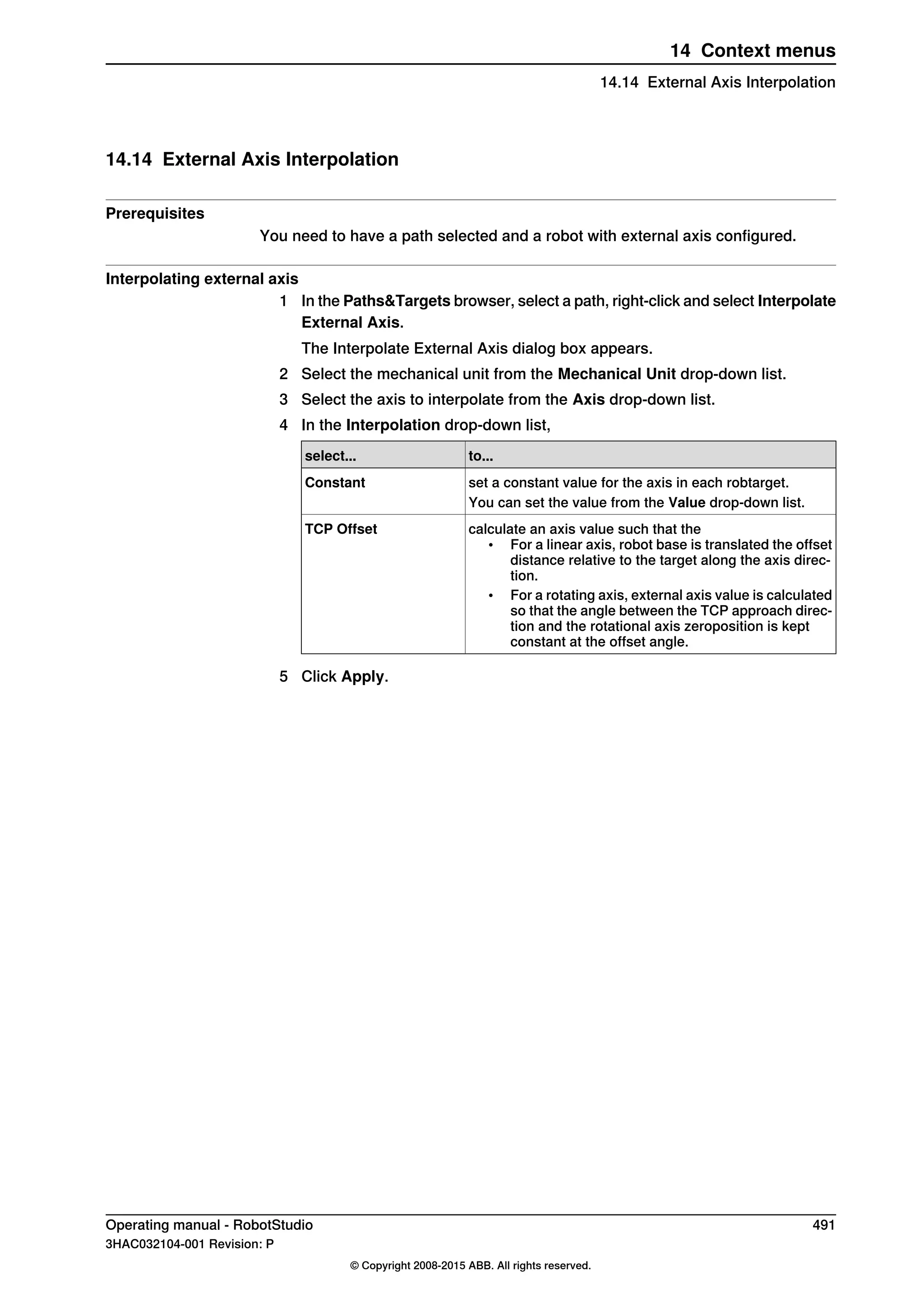
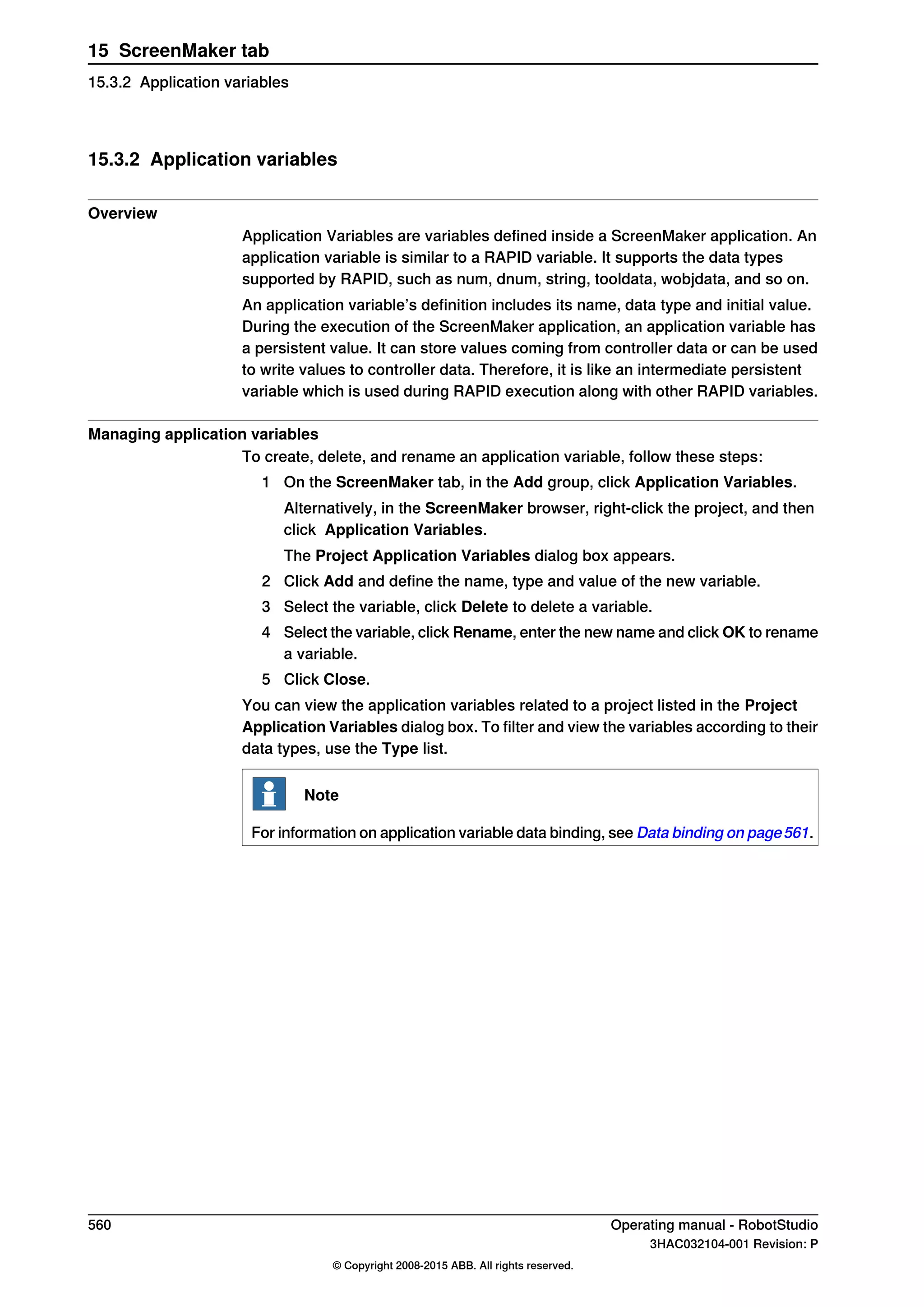
How to get radio buttons to show state when entering
The objective is to have two radio buttons that controls one digital output. When
the screen is loaded, the buttons should show the current state of the output.
Actions
Create a group or a panel and place the two radio buttons on the group or panel.
For button1, set the property default value to True and bind the property to the
value of the controller digital output signal.
For button2, do not do any changes.
When the screen is loaded, the state of the two radio buttons is established
correctly.
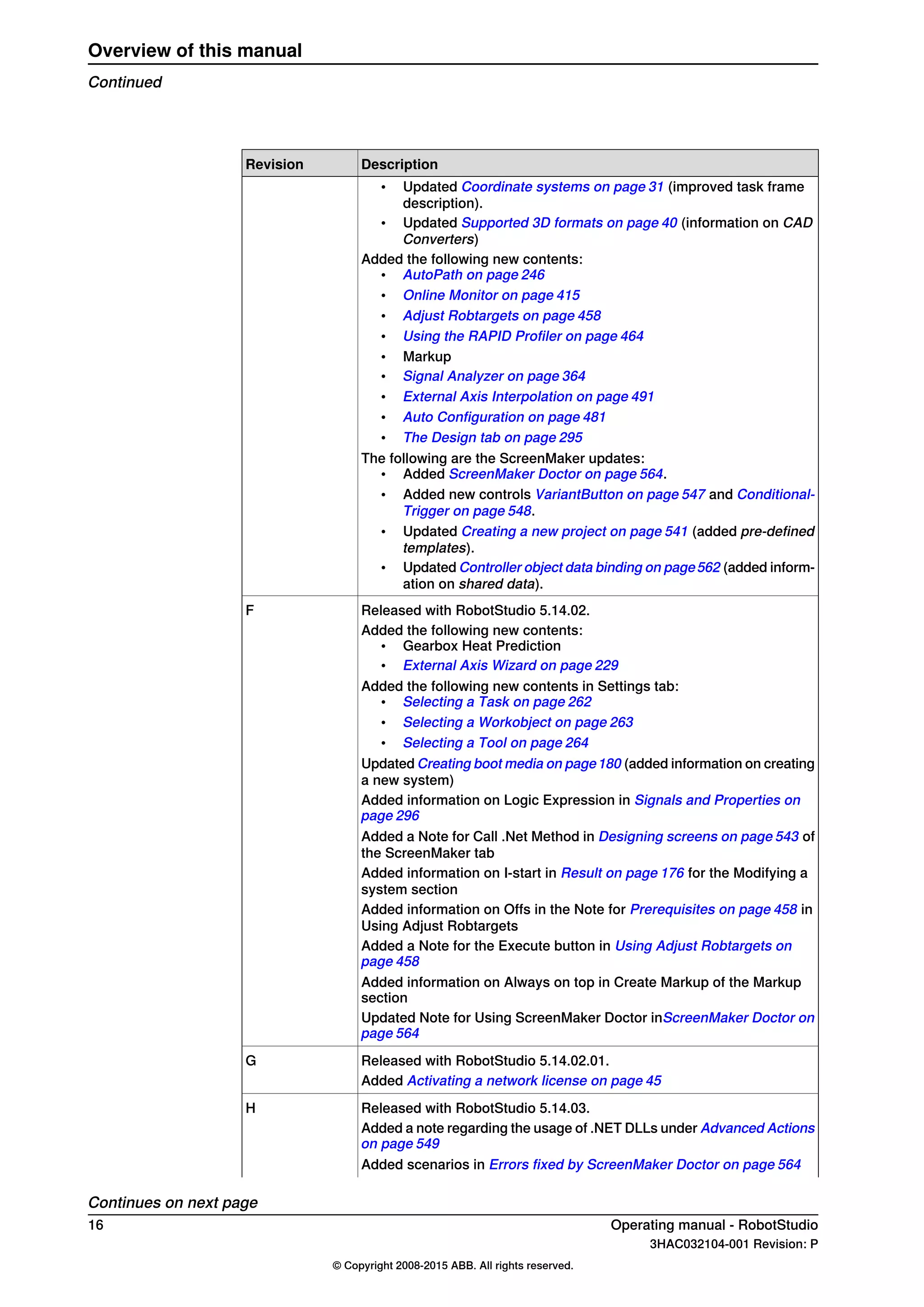
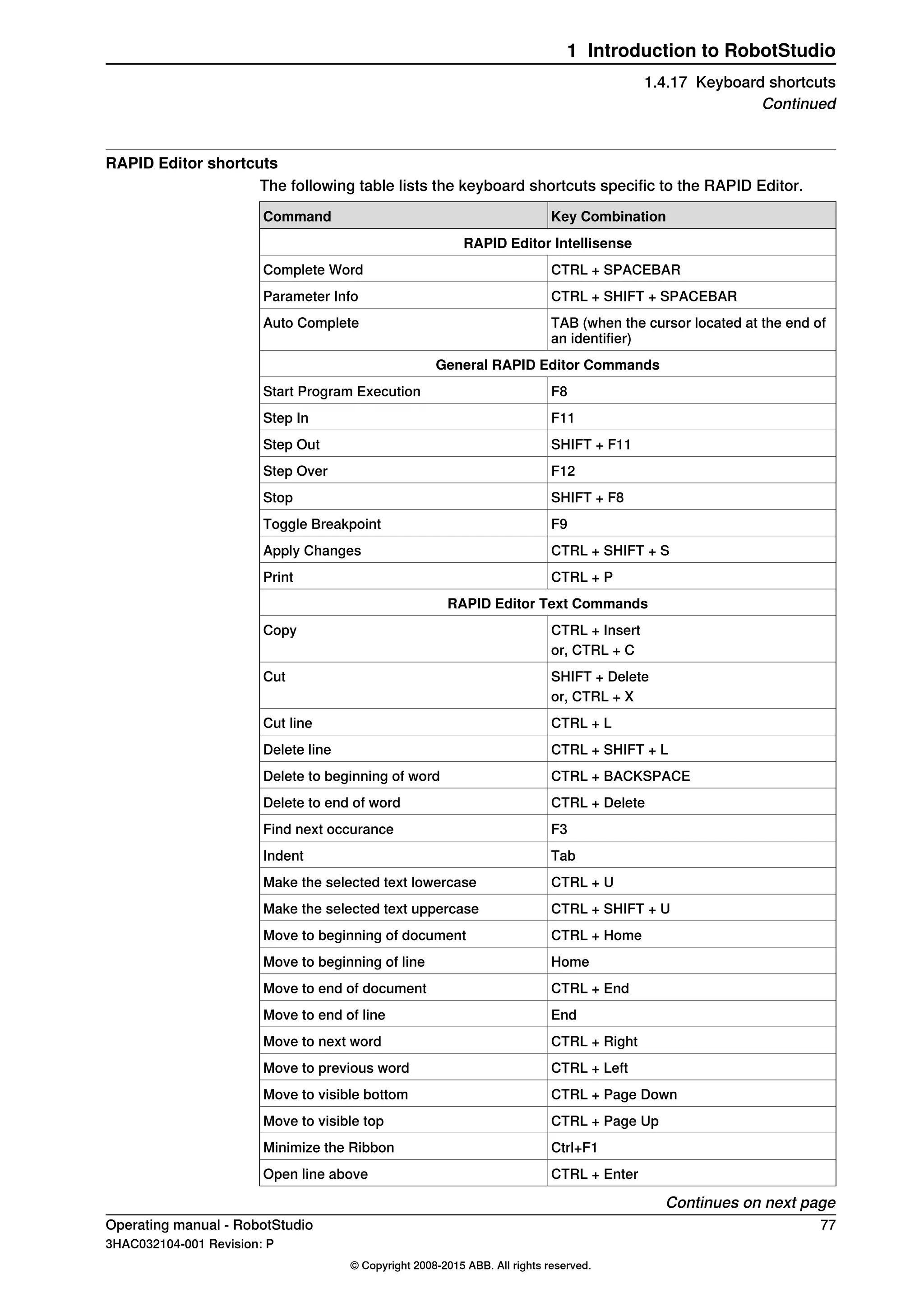
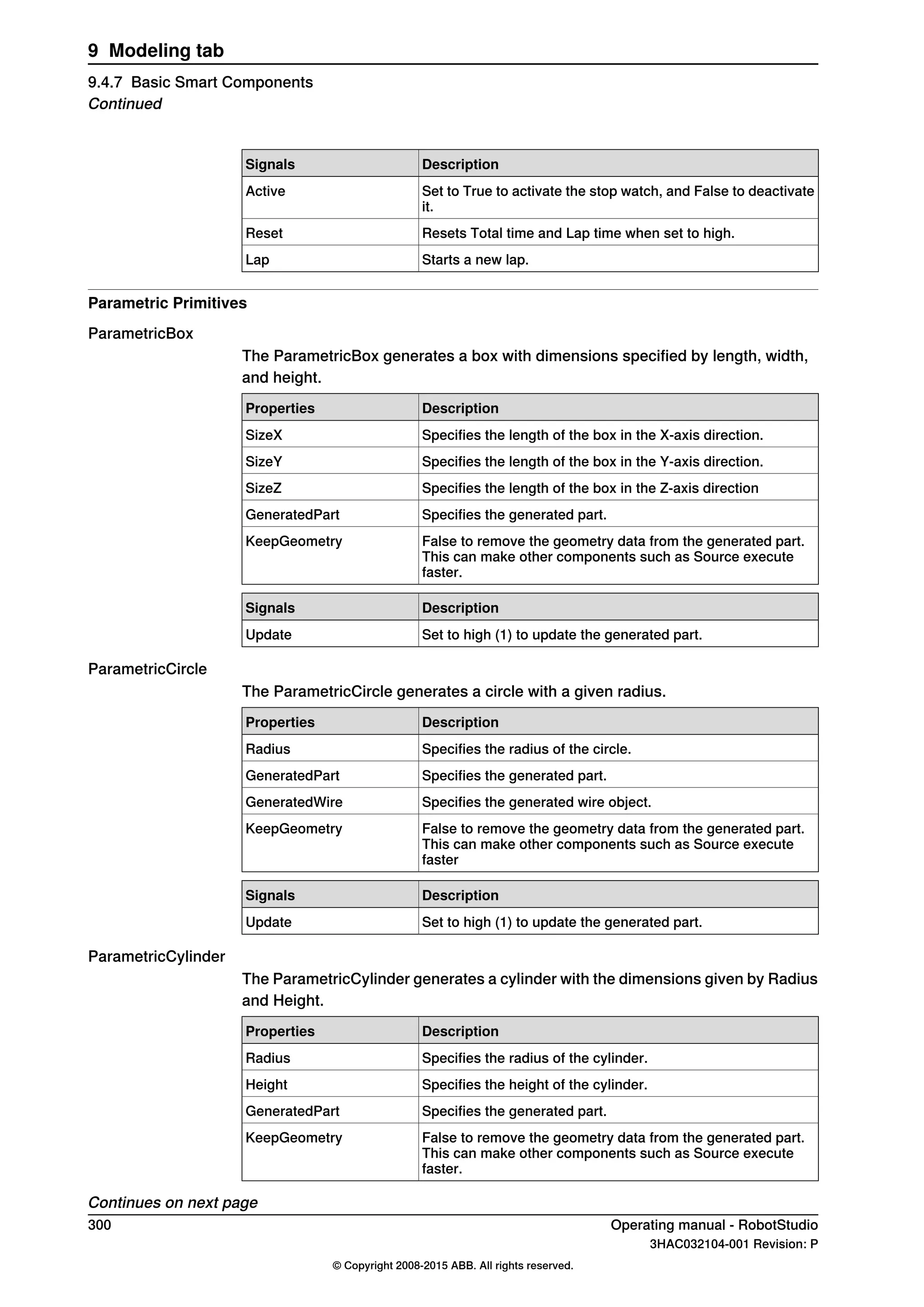
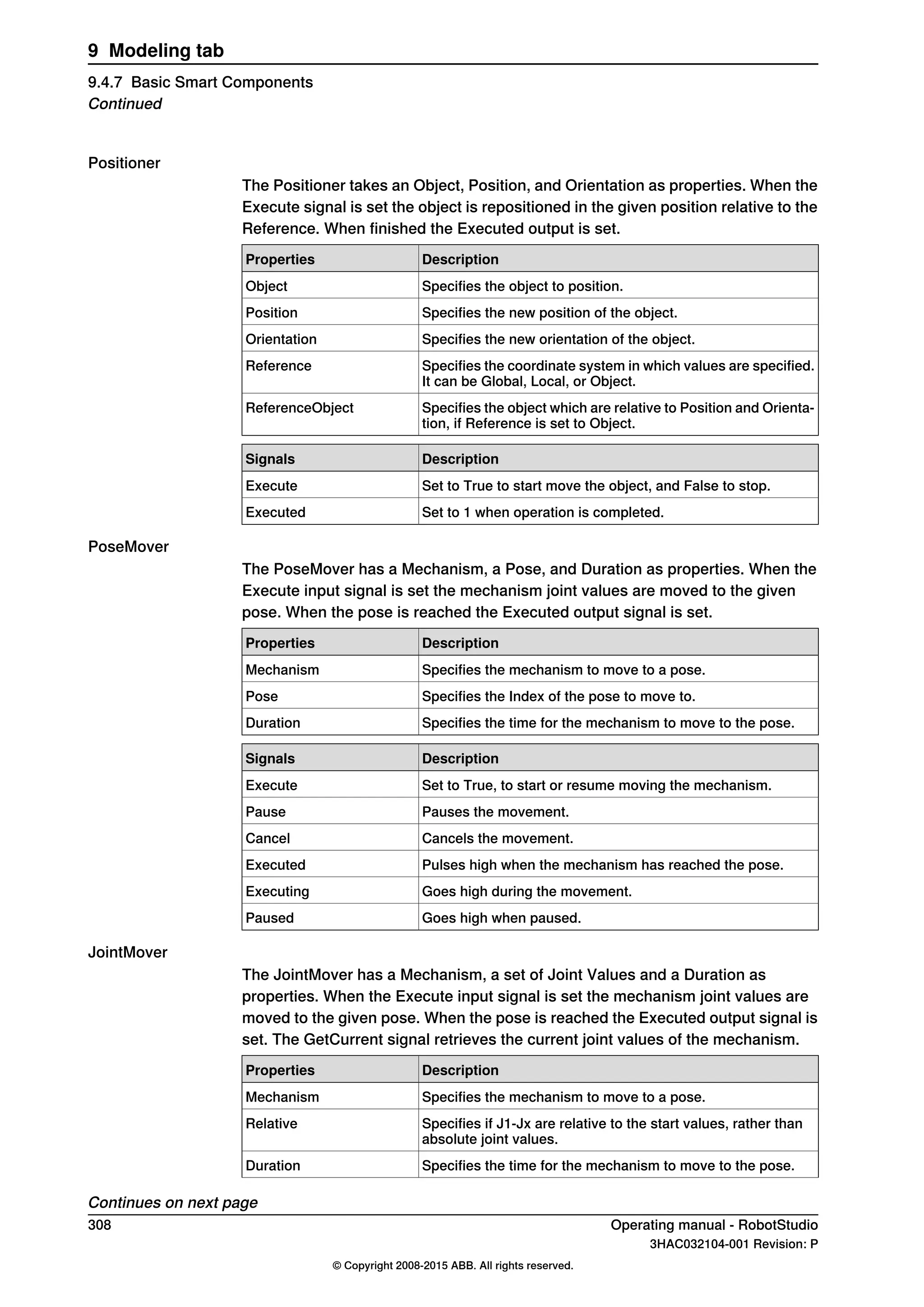
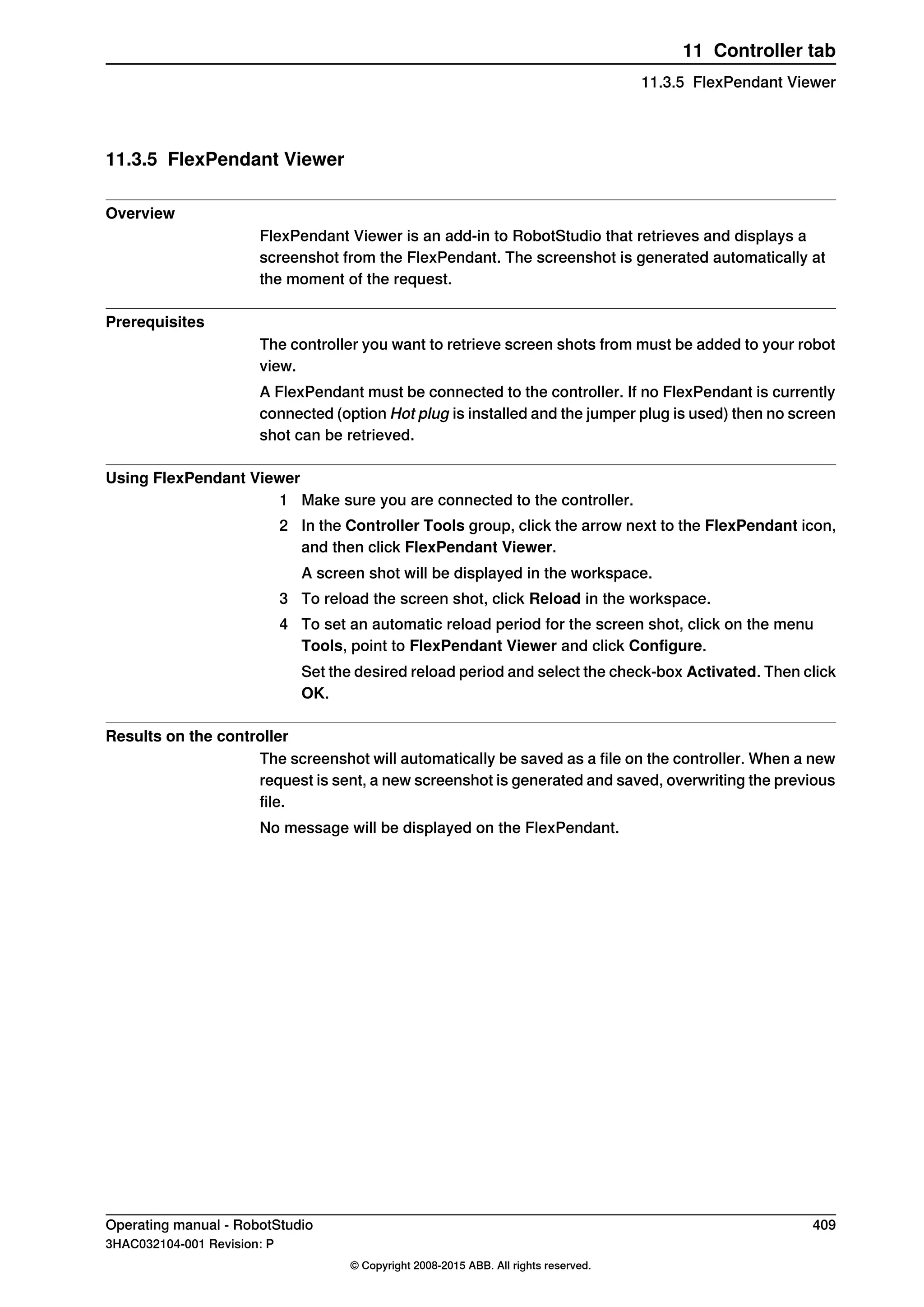
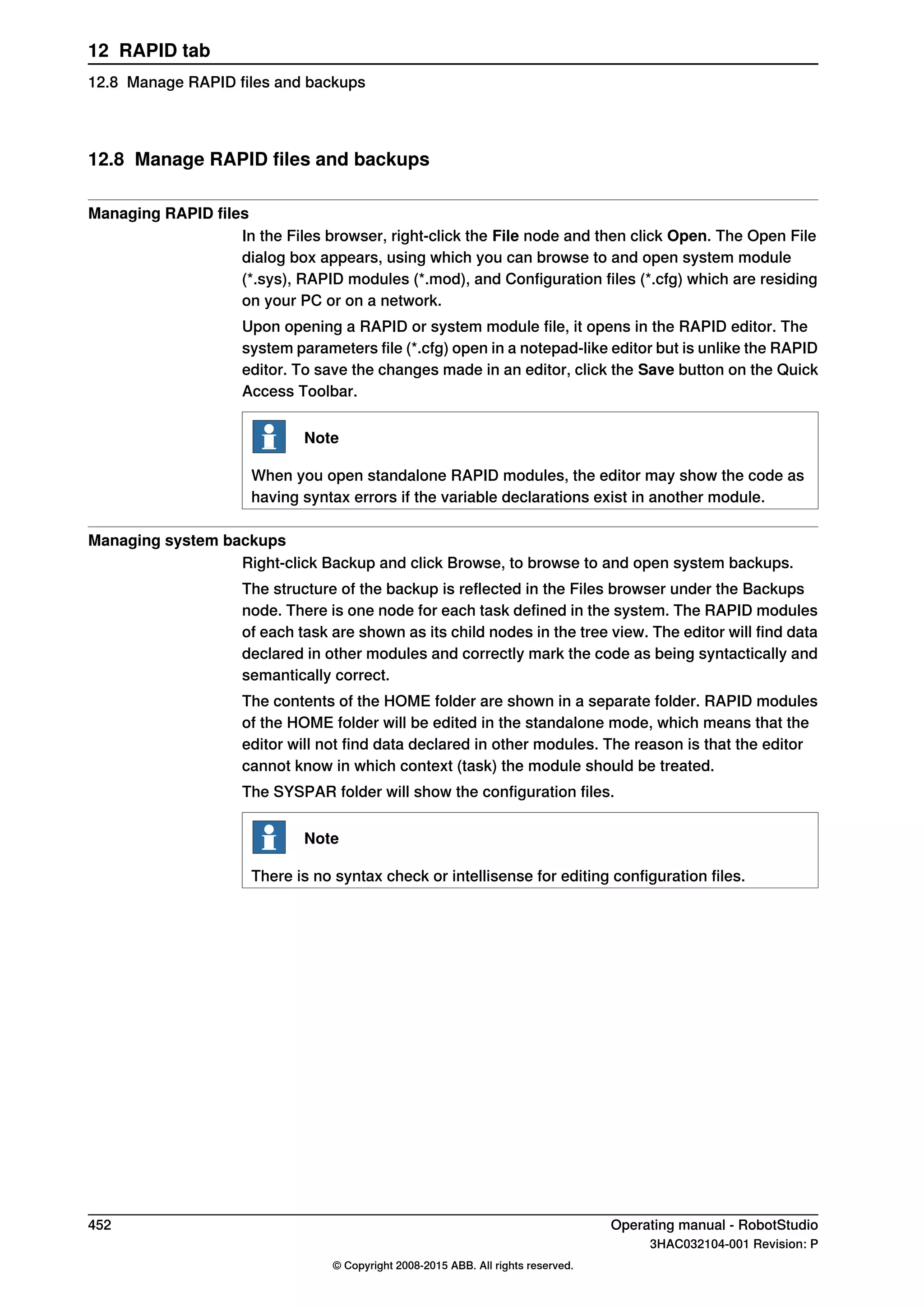
What is RAPID array
A RAPID array is a variable that contains more than one value. An index is used
to indicate one of the values.
Sample RAPID array
Consider the following RAPID code.
VAR string part{3} := ["Shaft", "Pipe", "Cylinder"];
Here, ‘part’ is a RAPID array which consists of three values. The index of the array
in part ranges from 1 to 3.
The index of a RAPID array should not be negative and should start with 1.
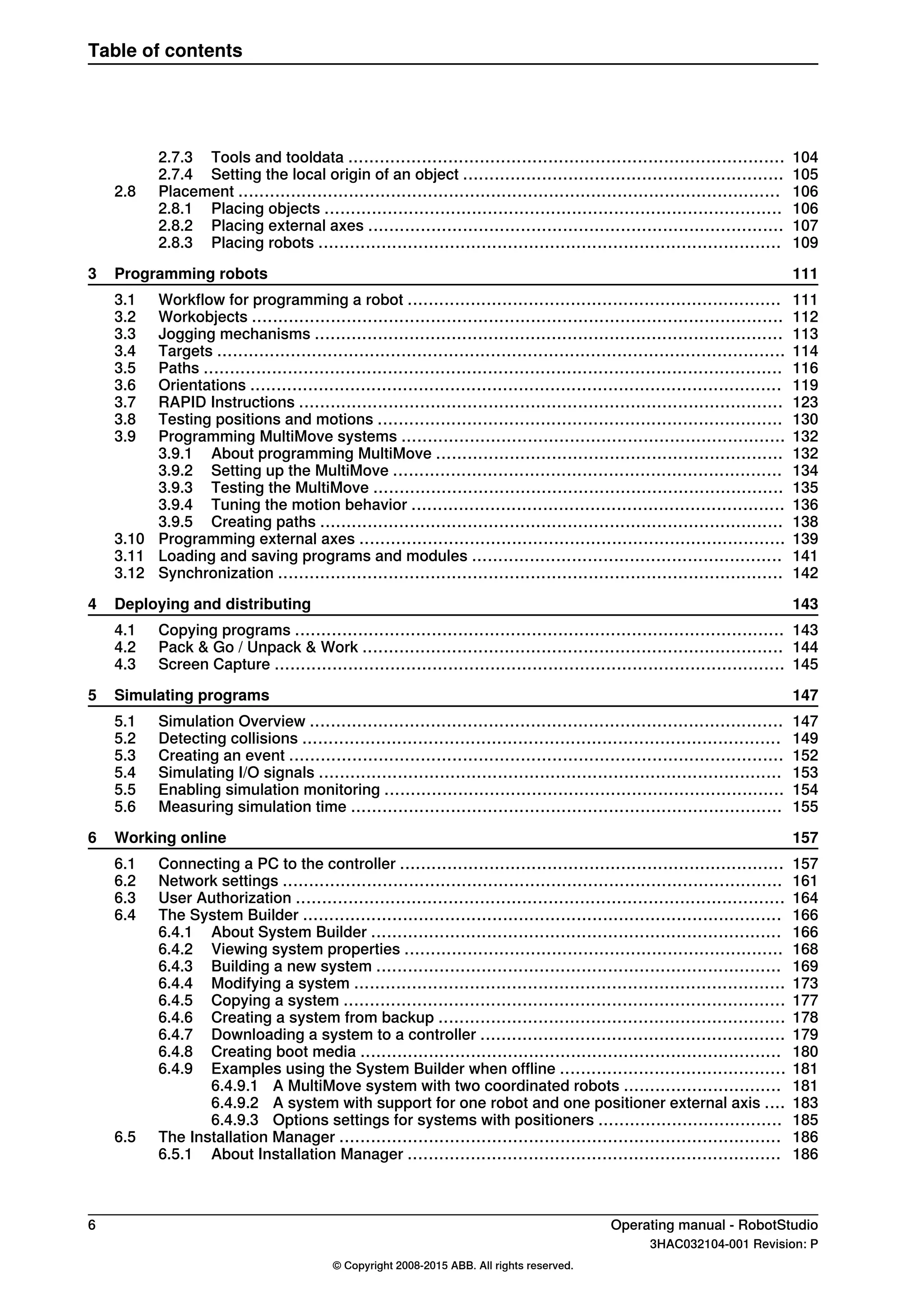
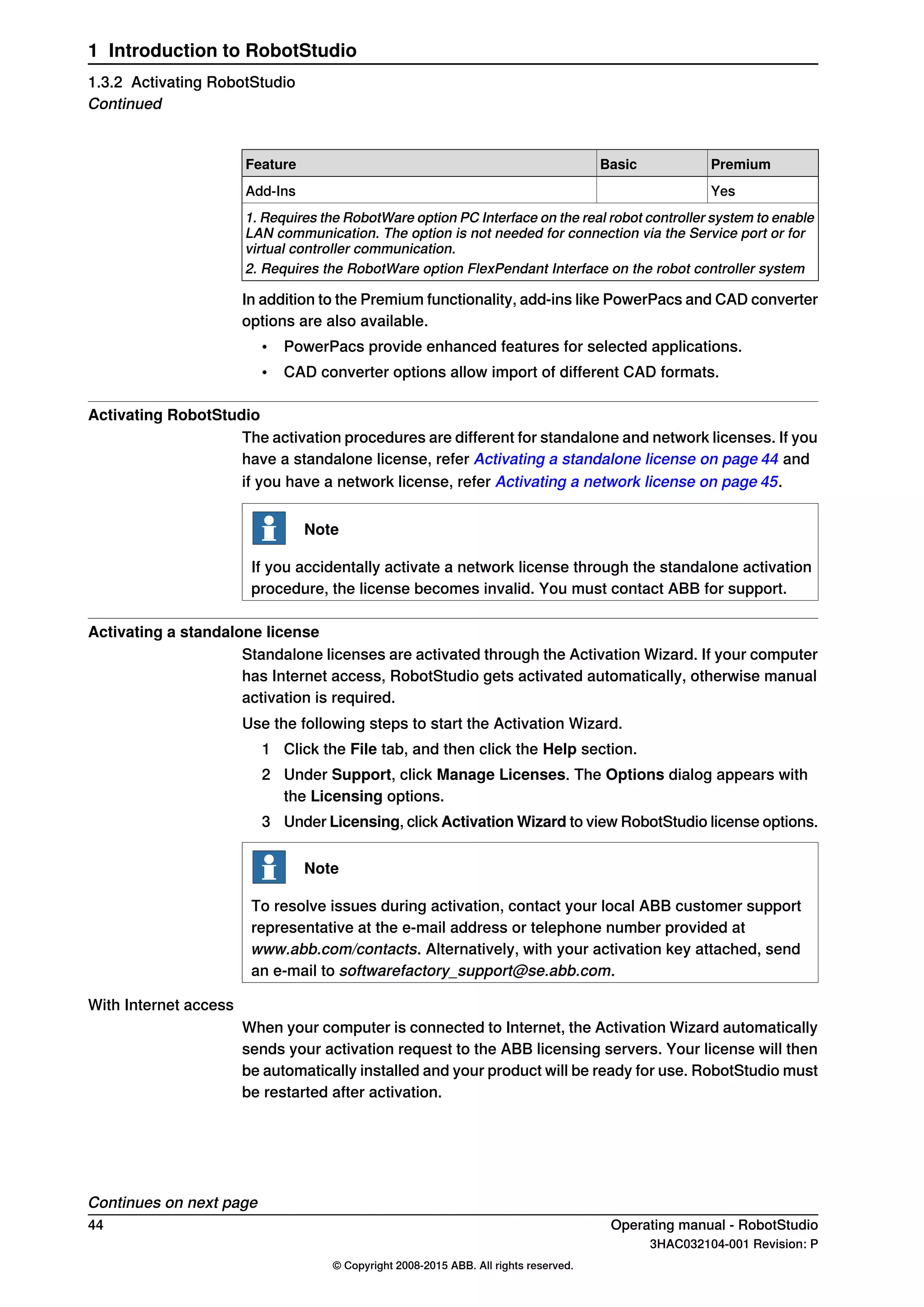
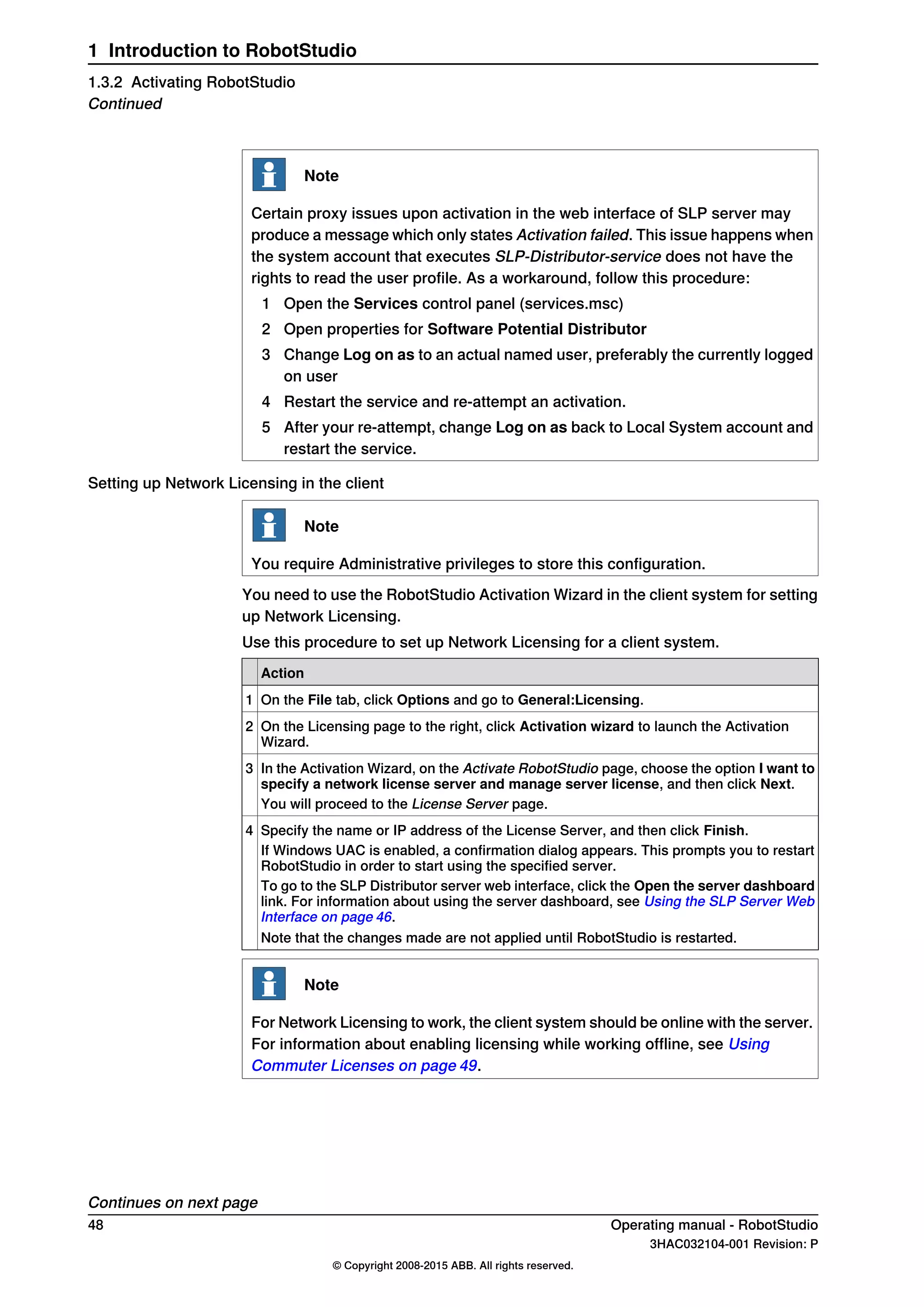
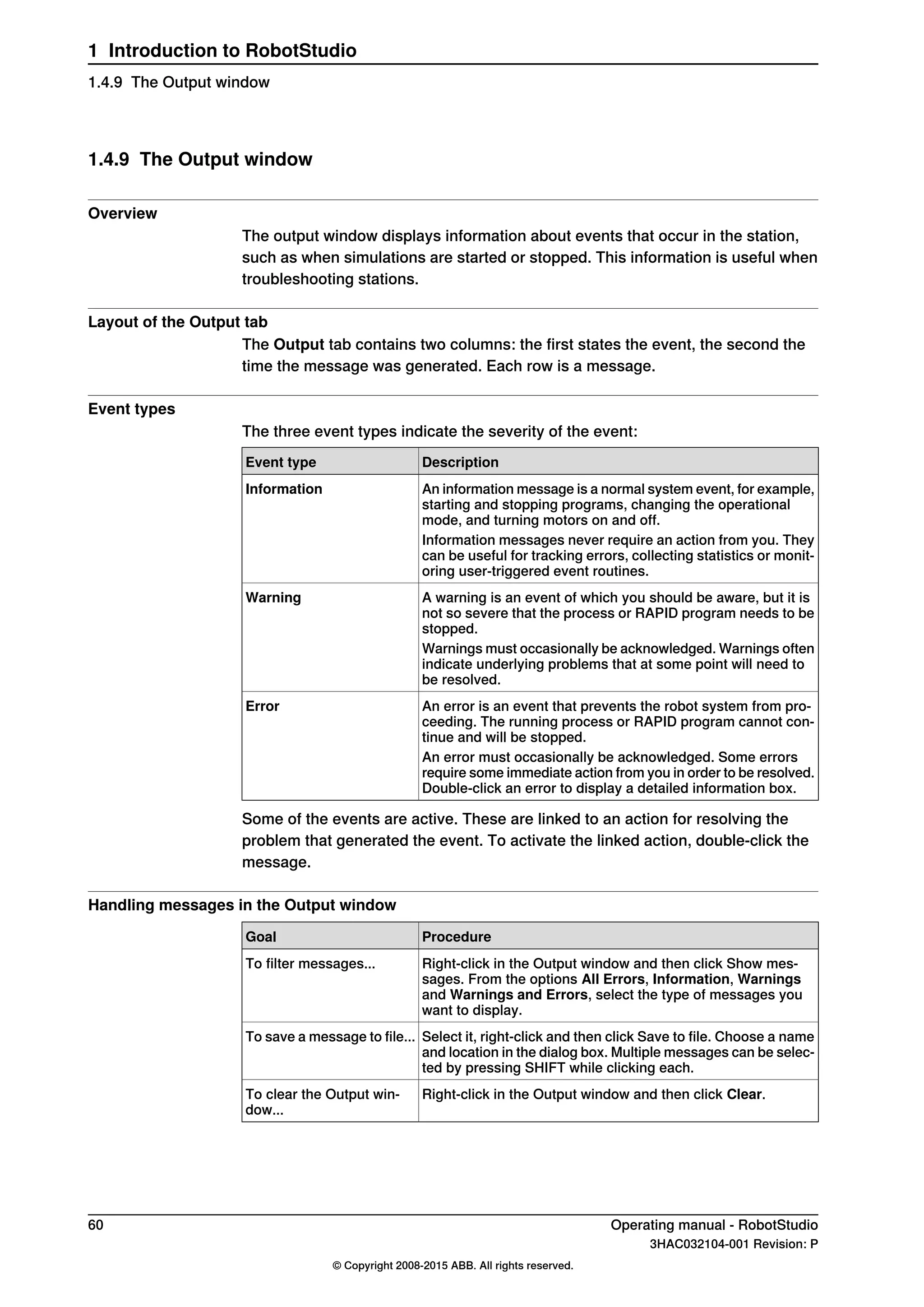
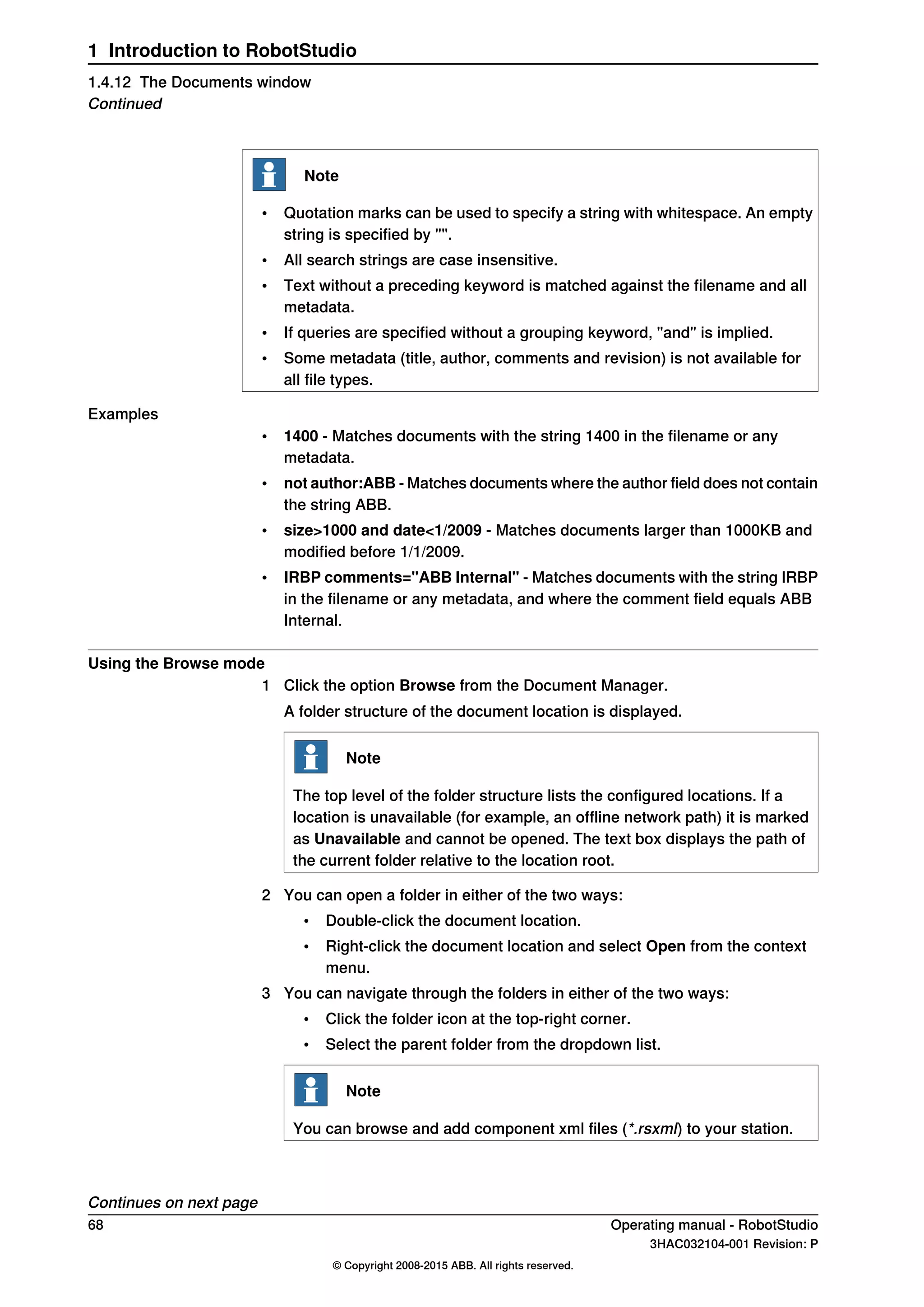
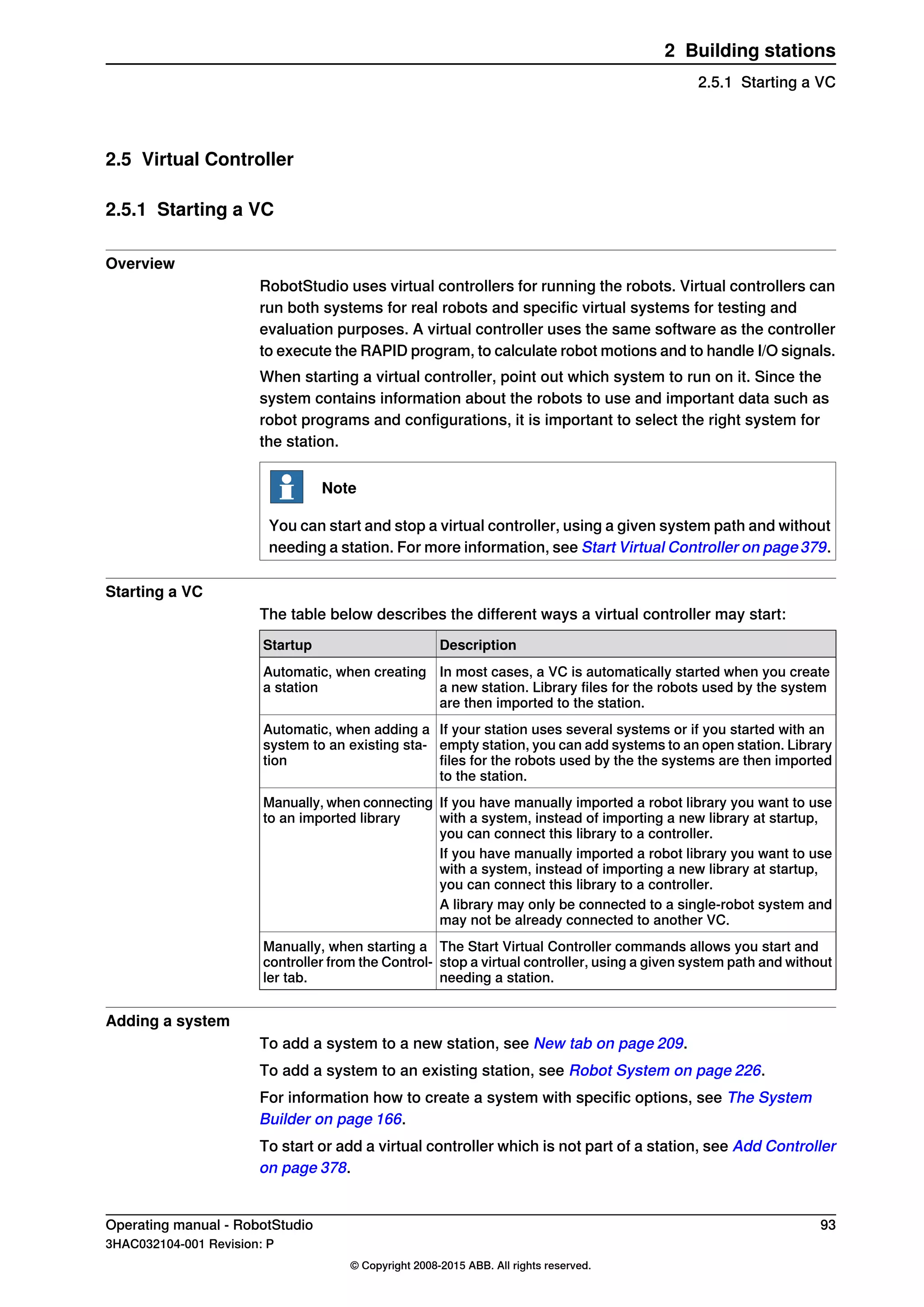
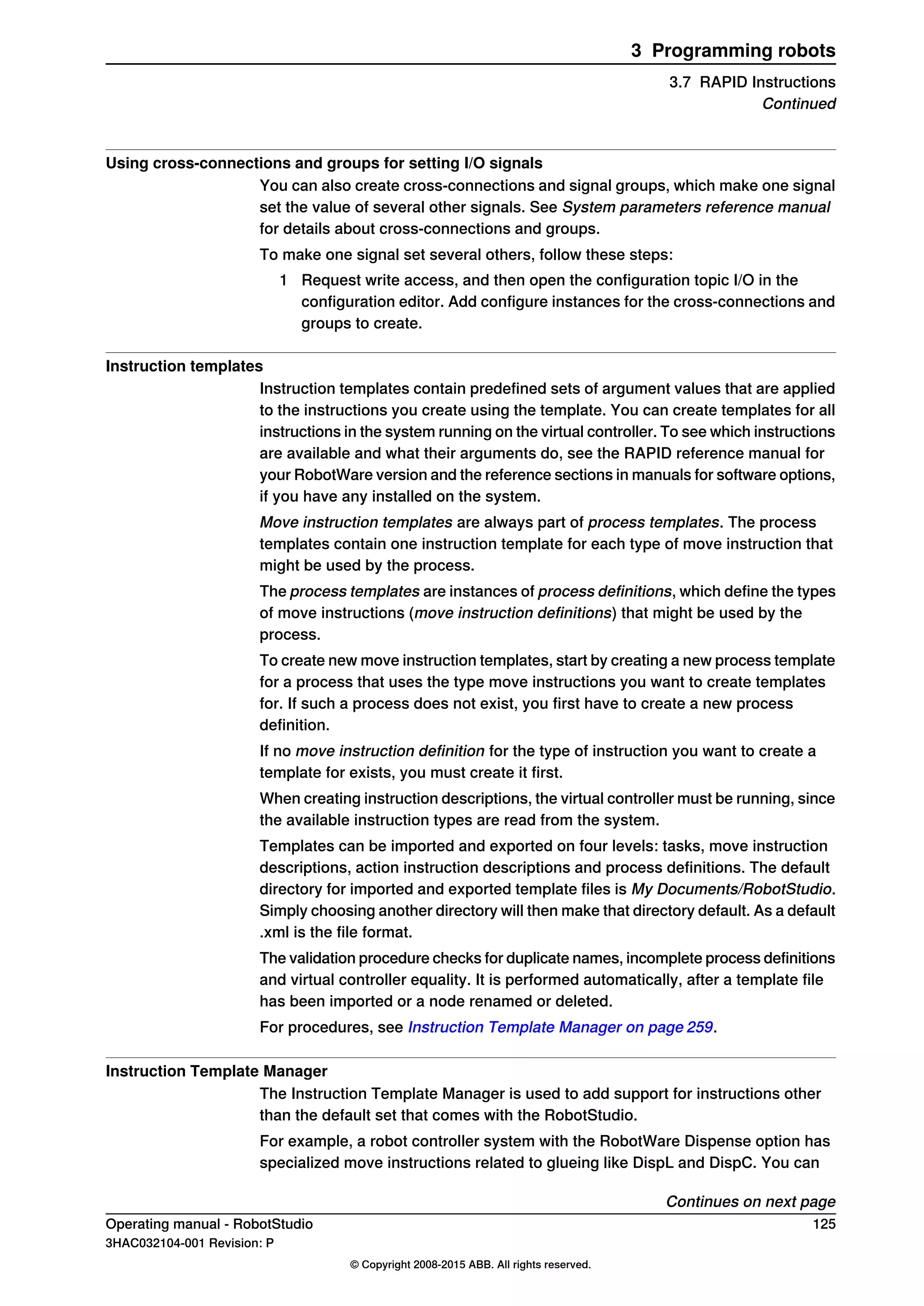
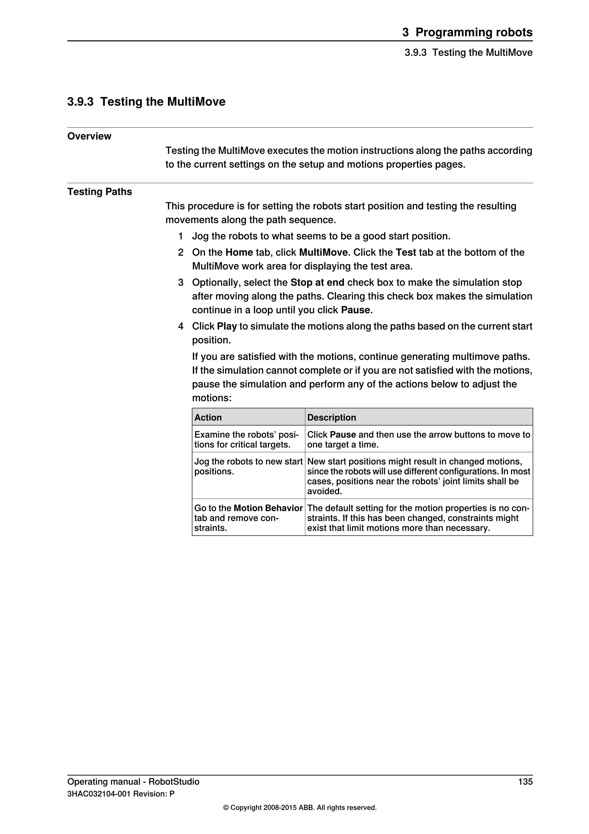
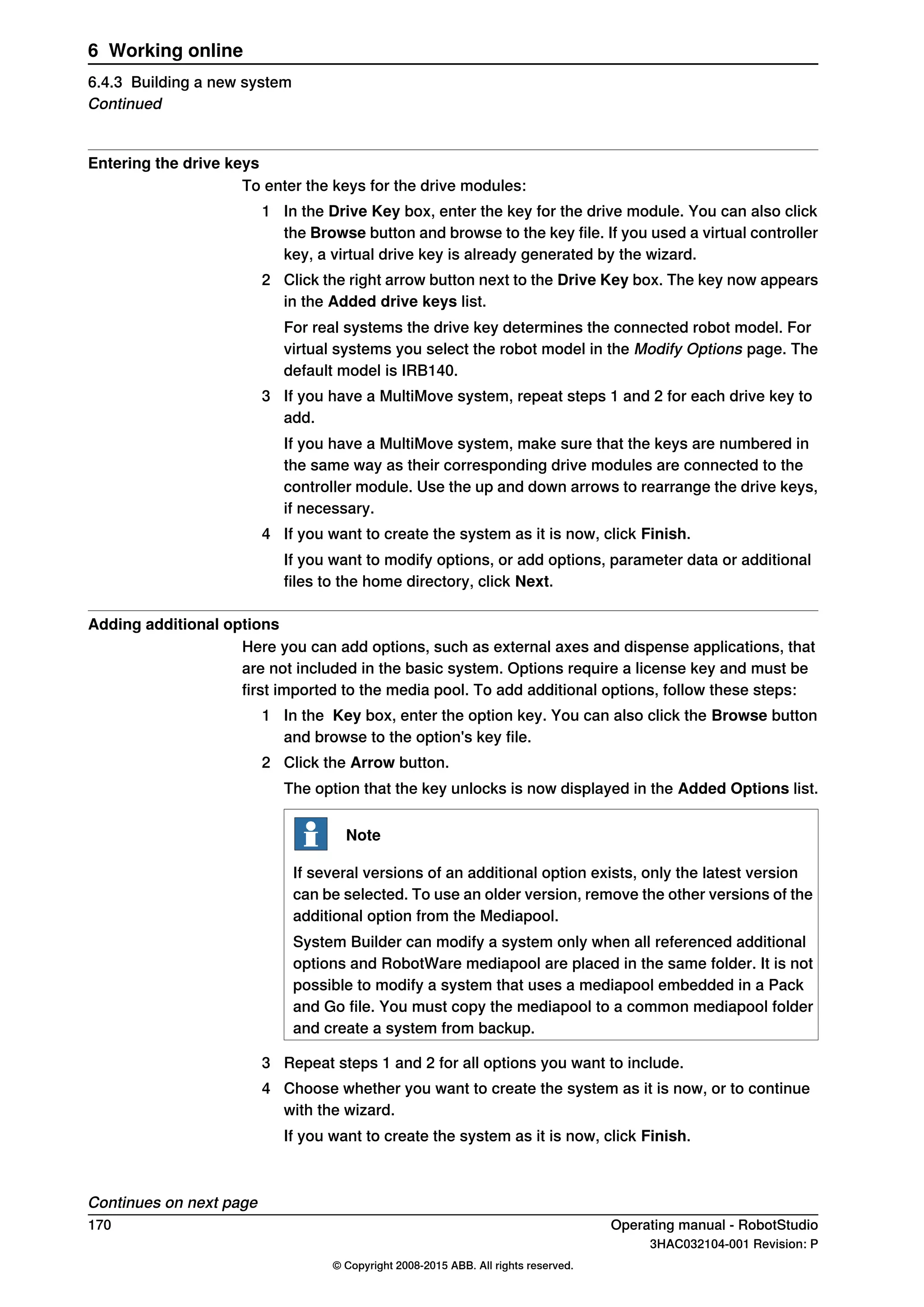
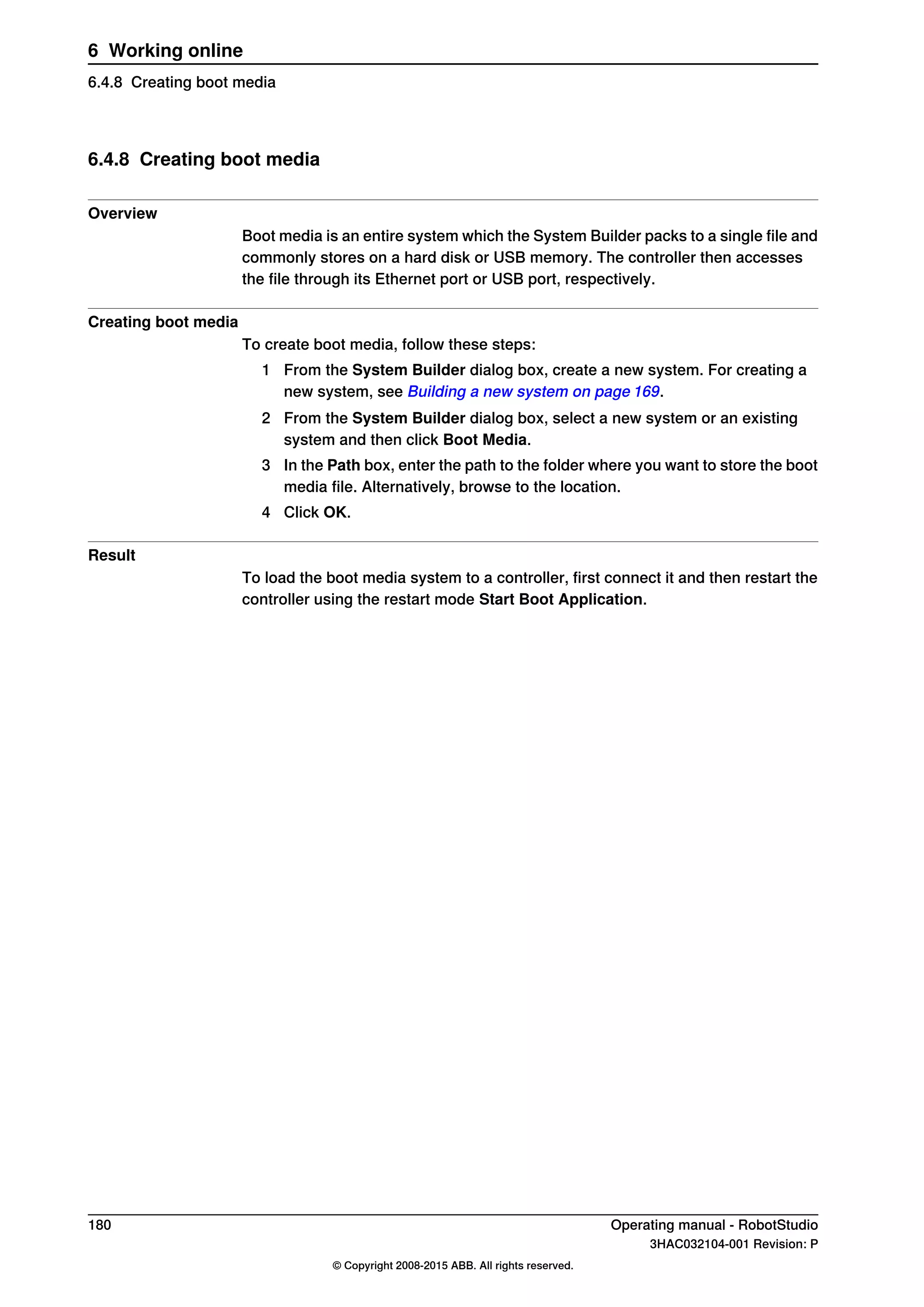
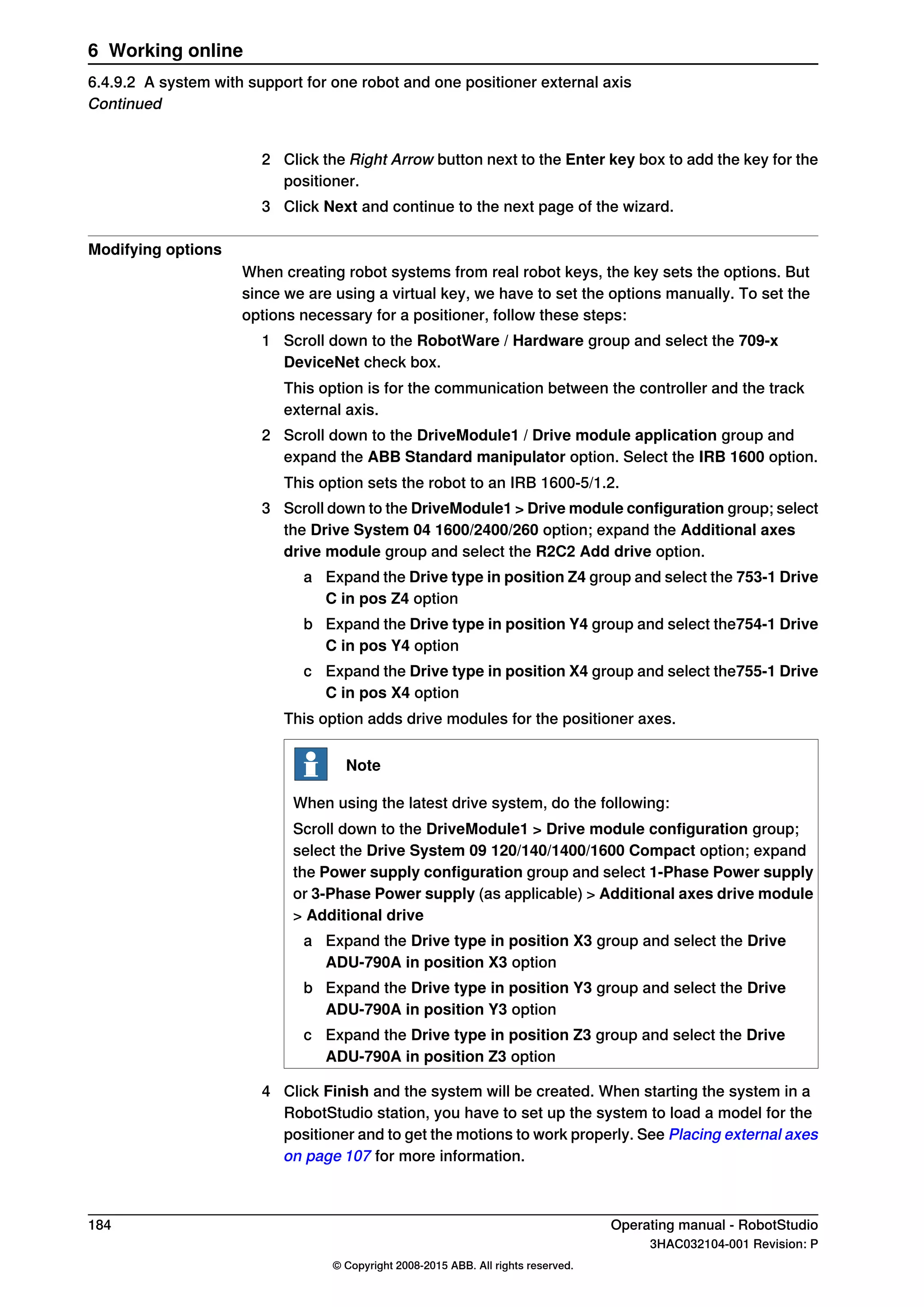
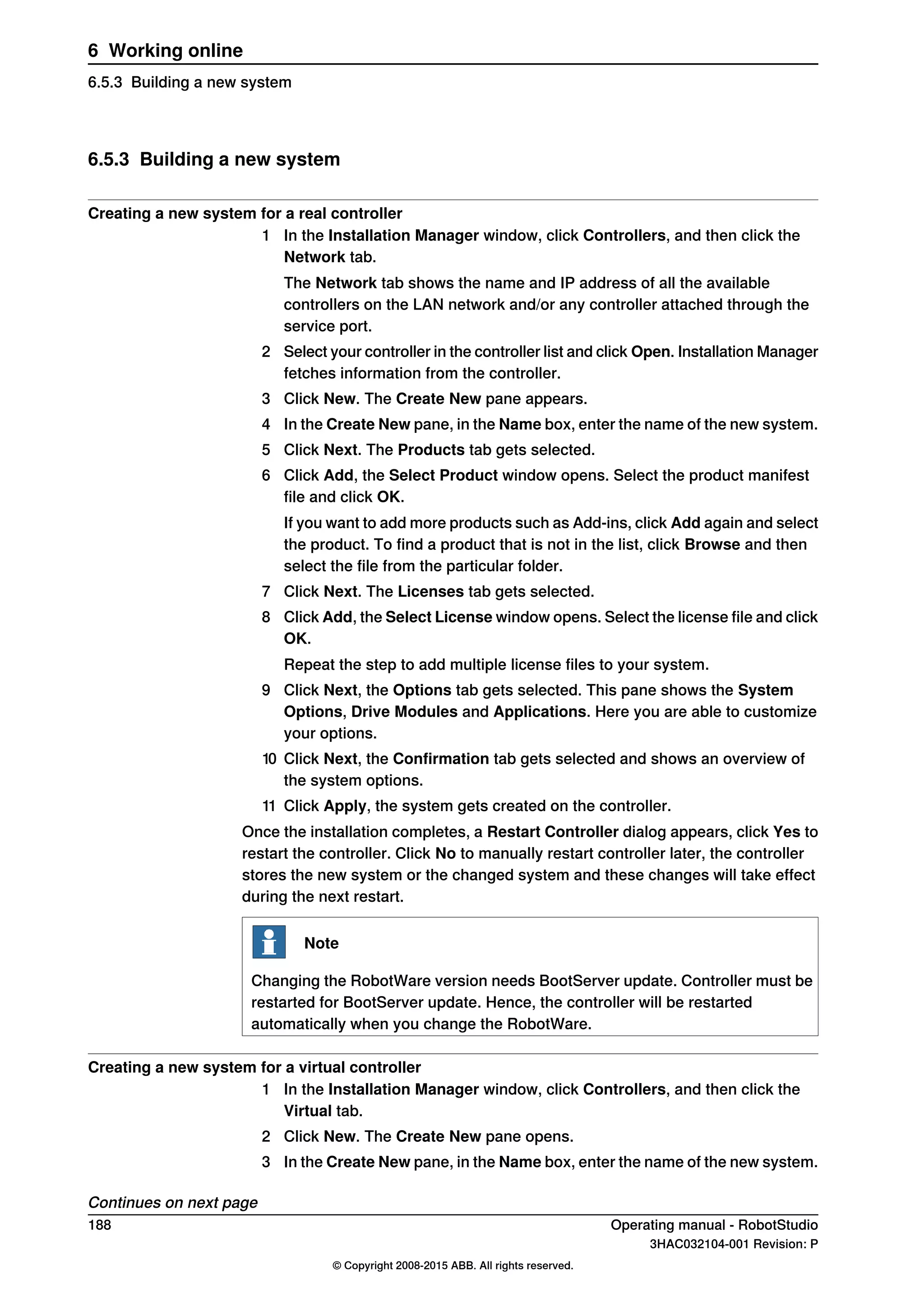
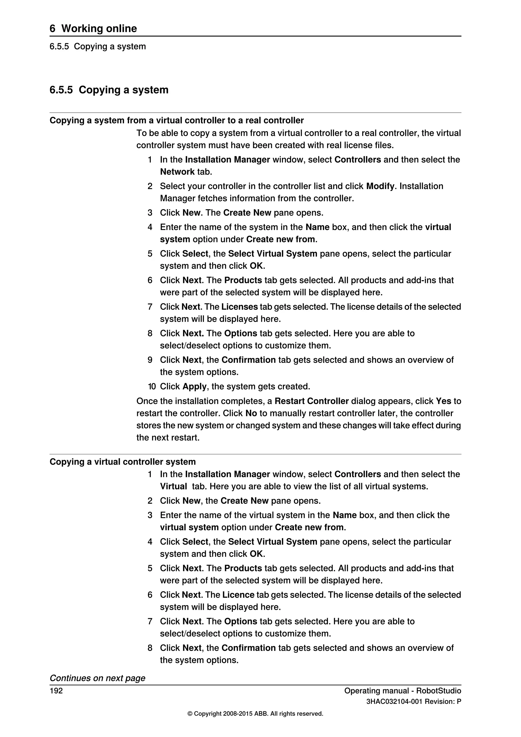
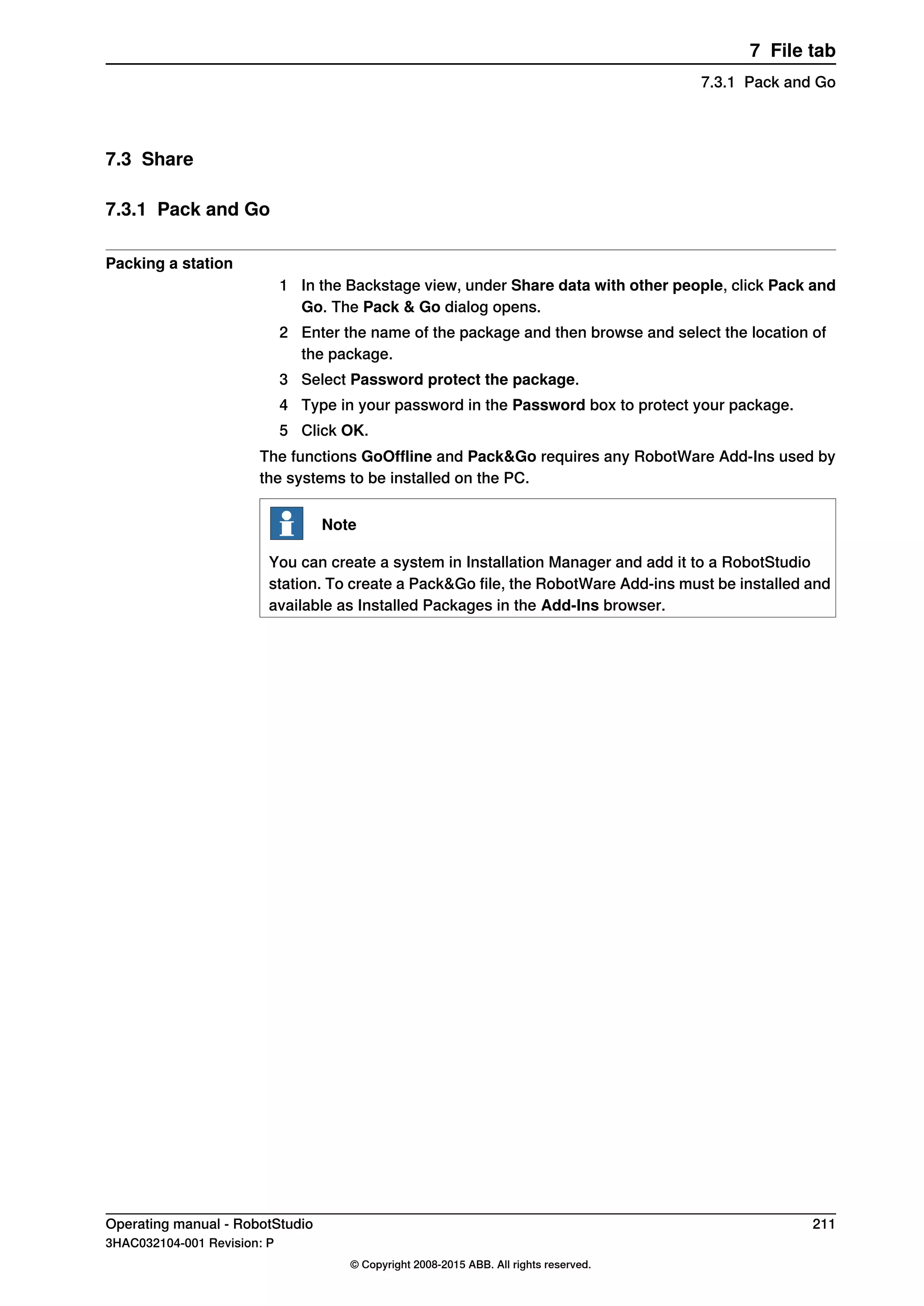
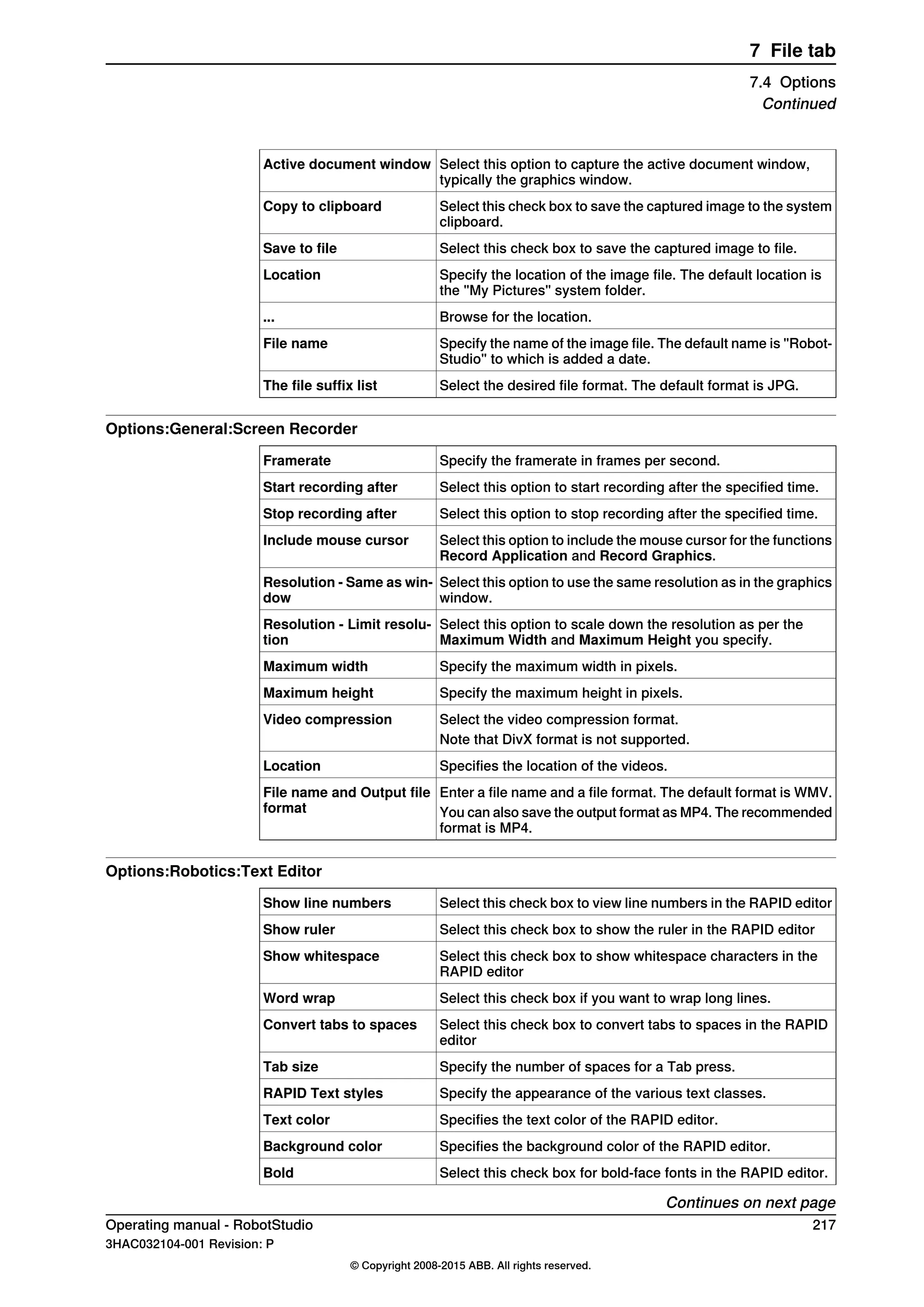
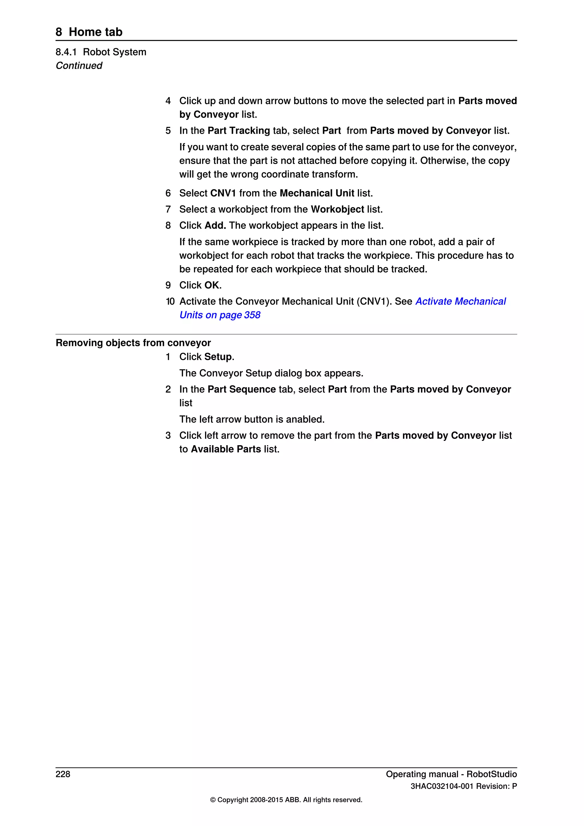
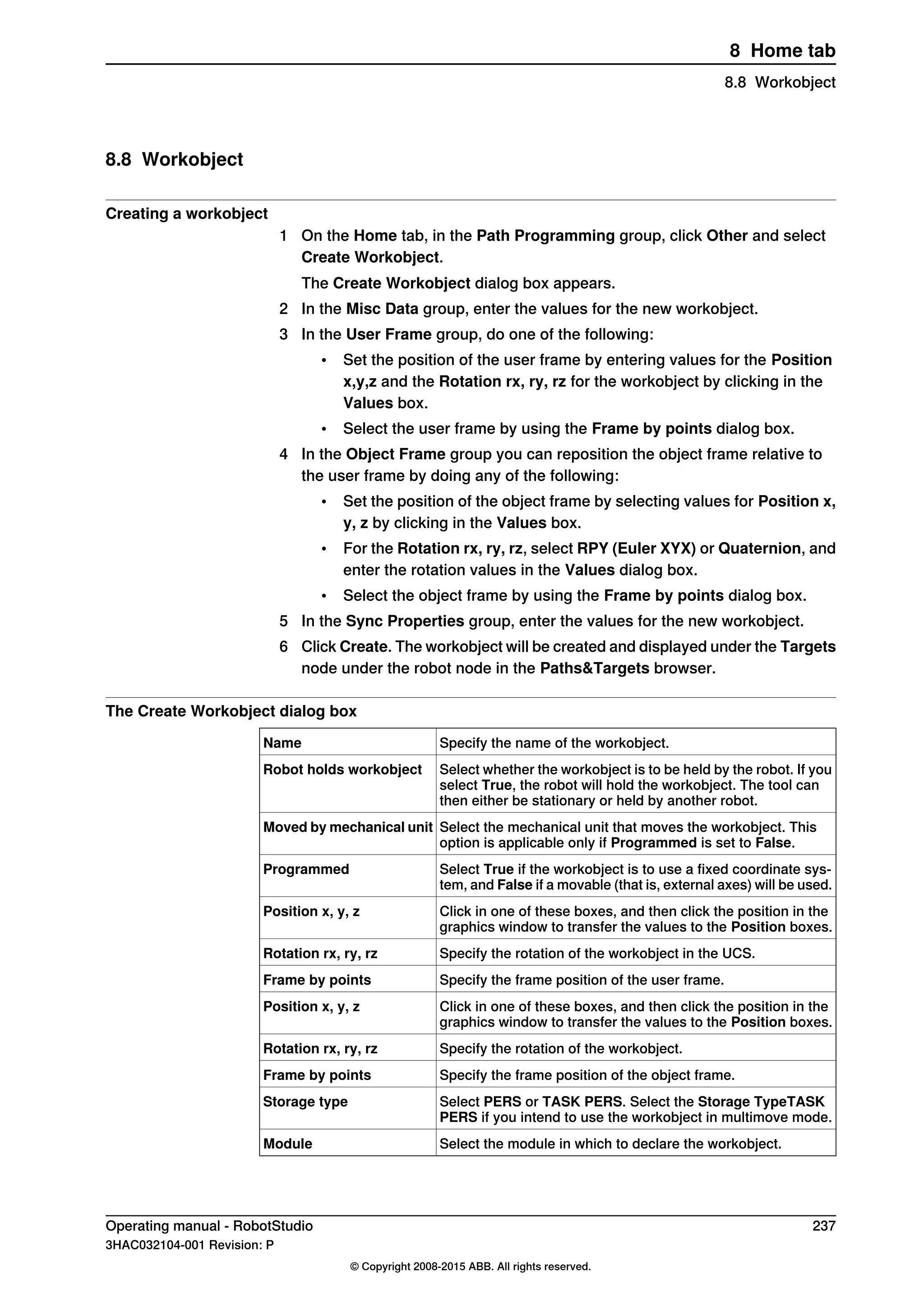
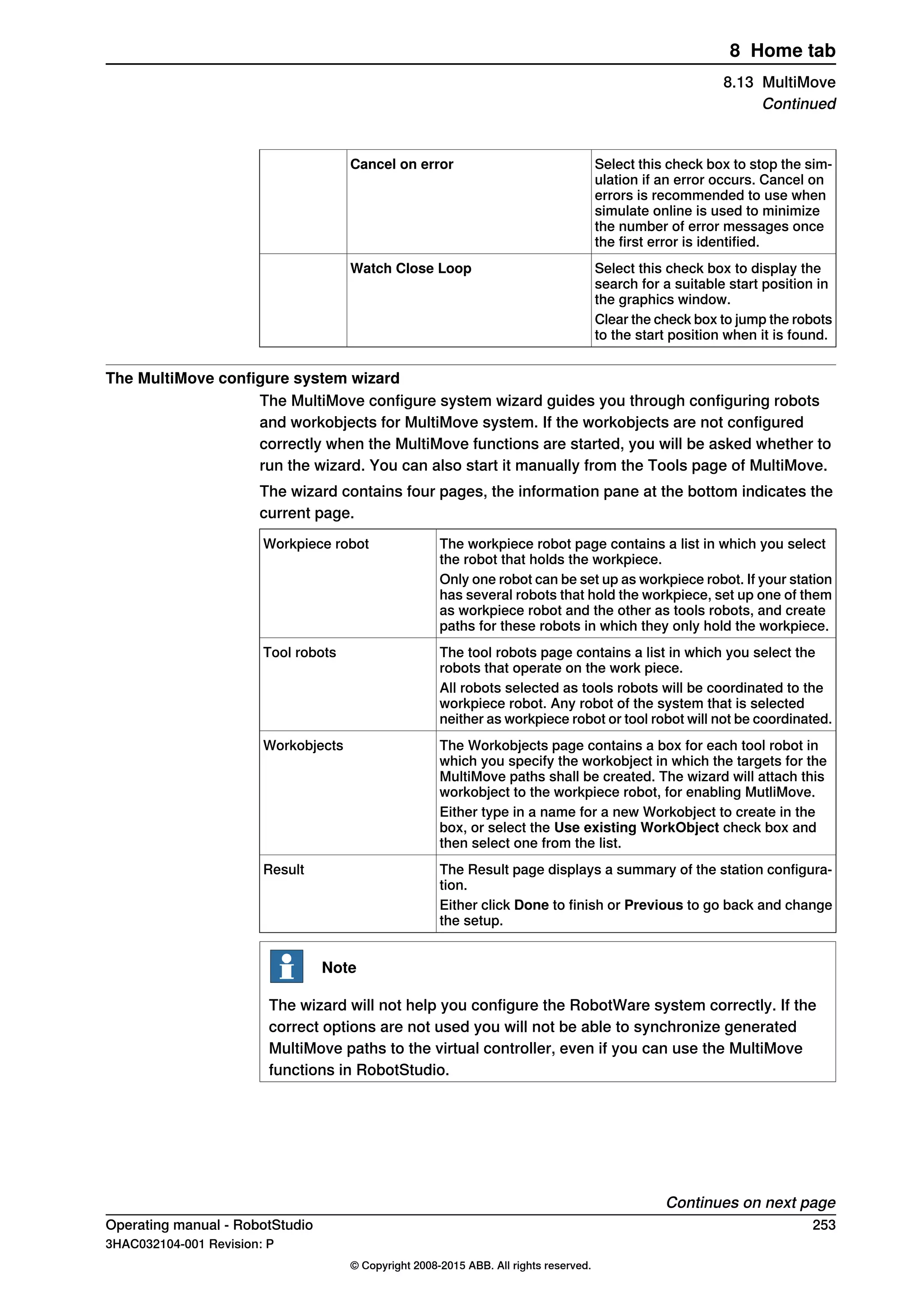
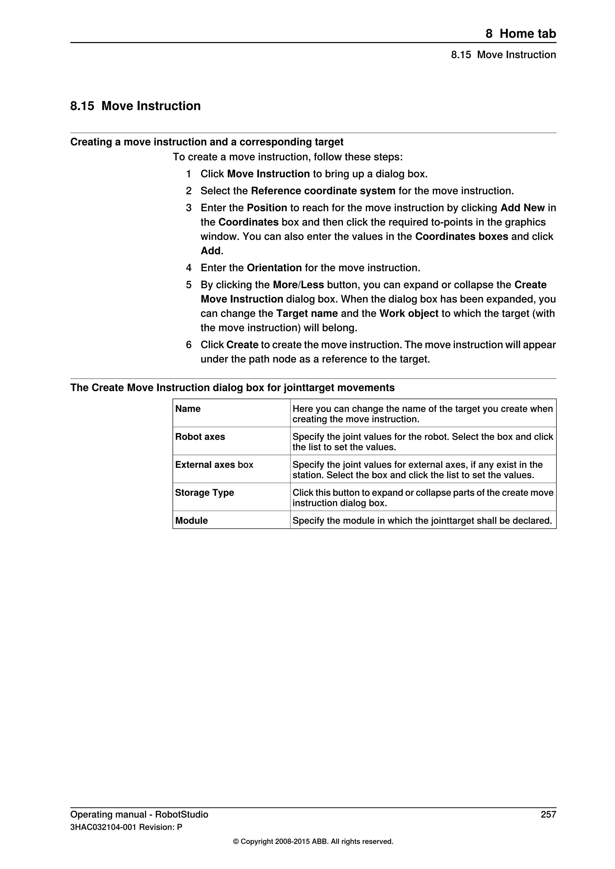
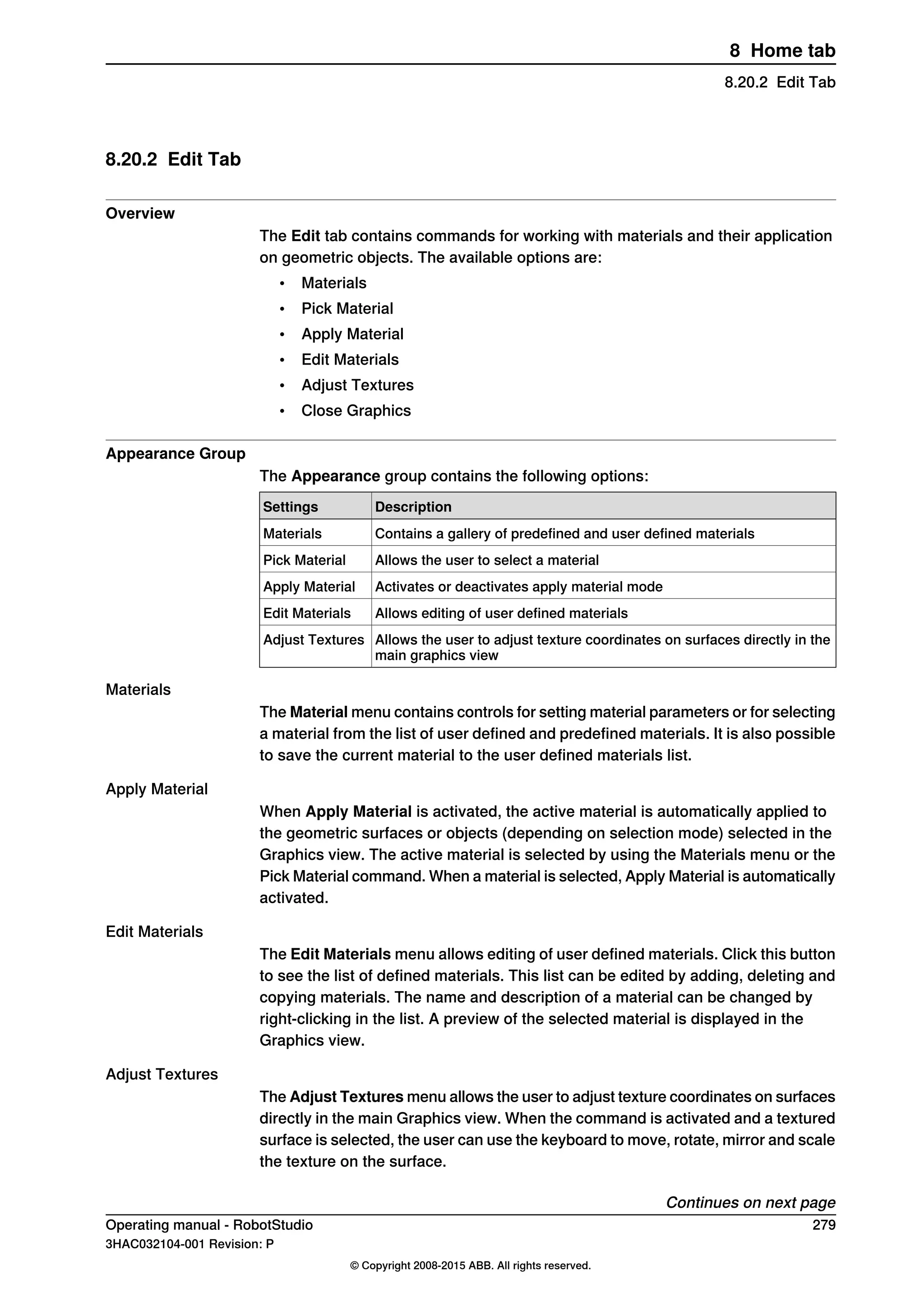
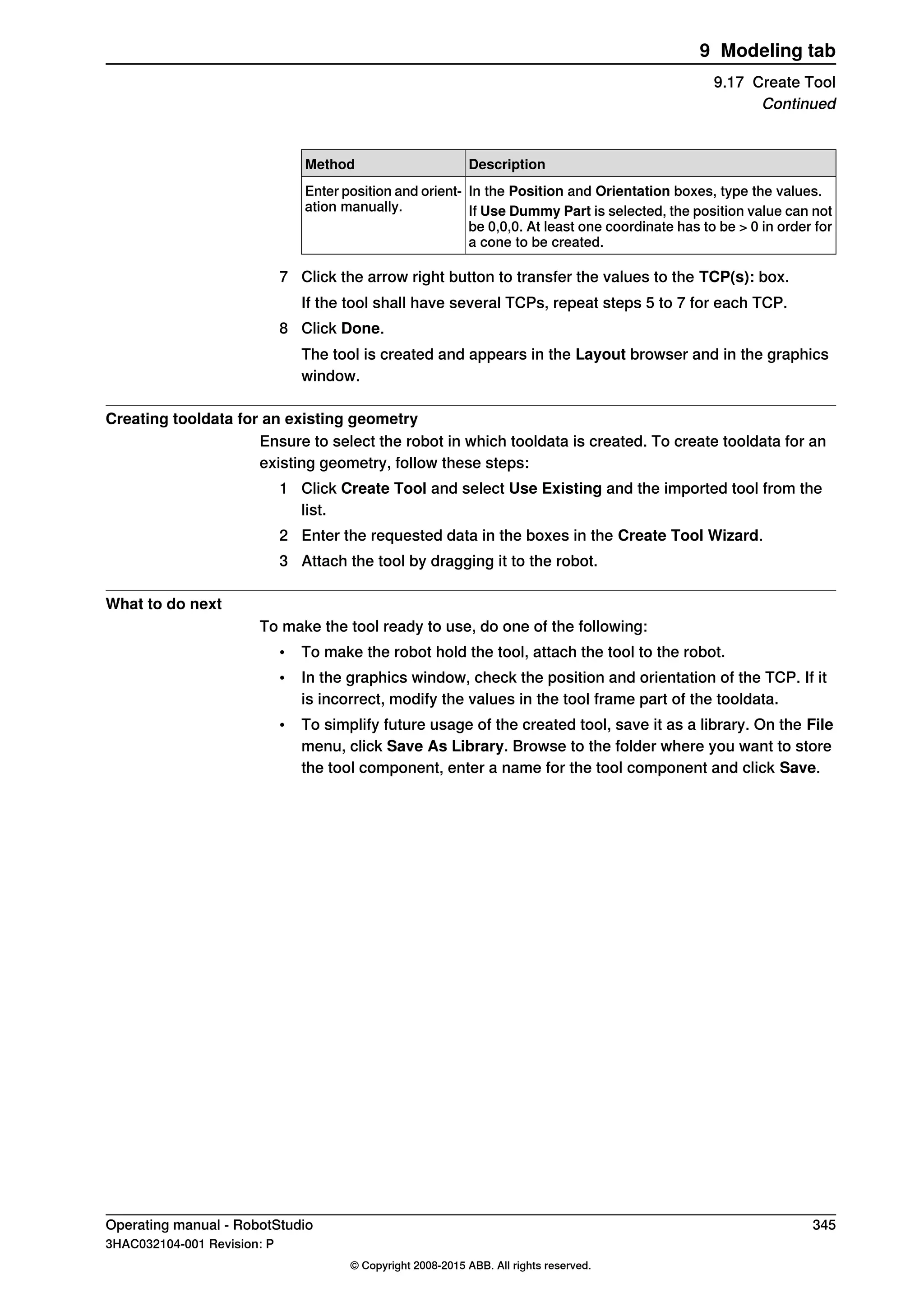
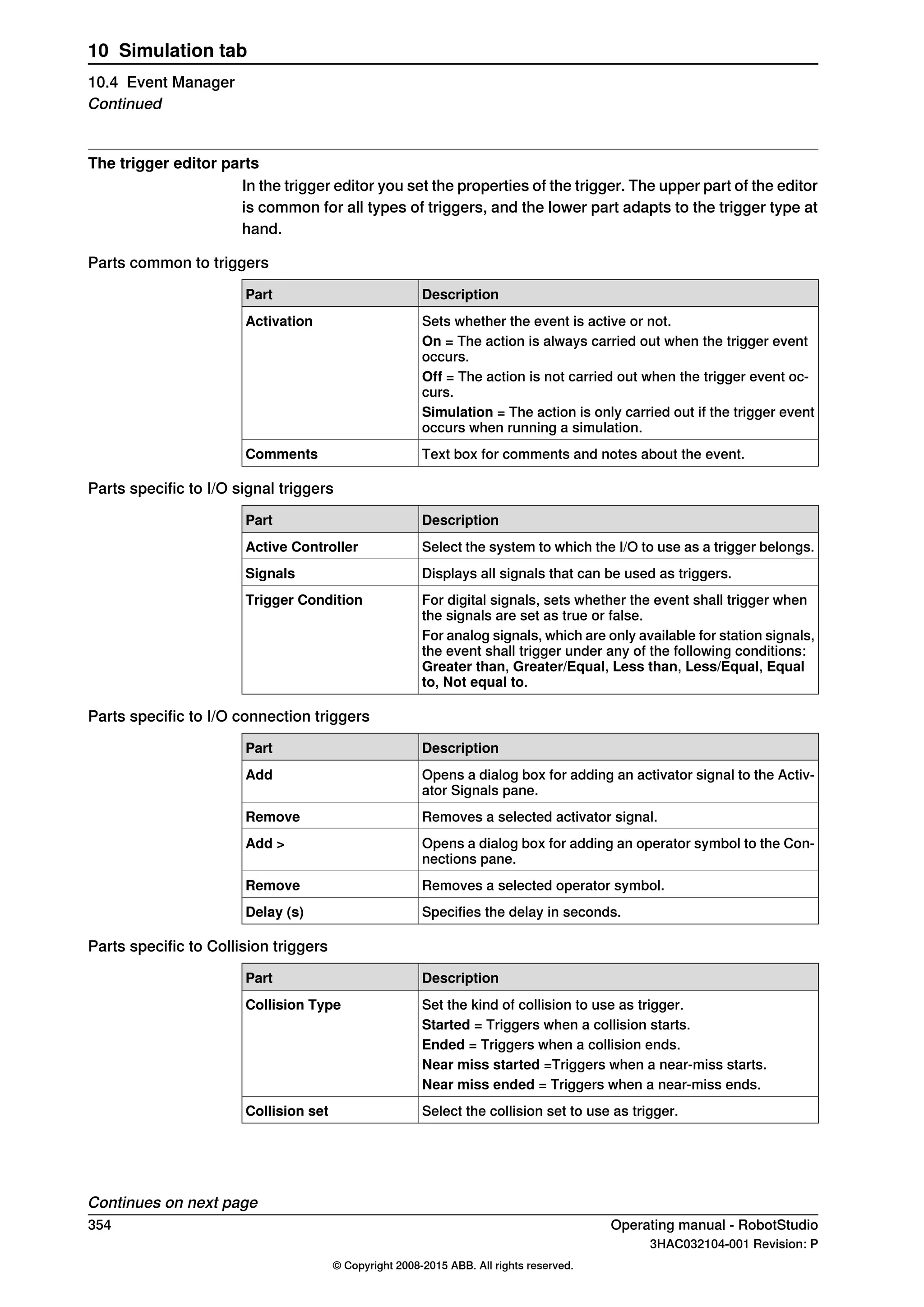
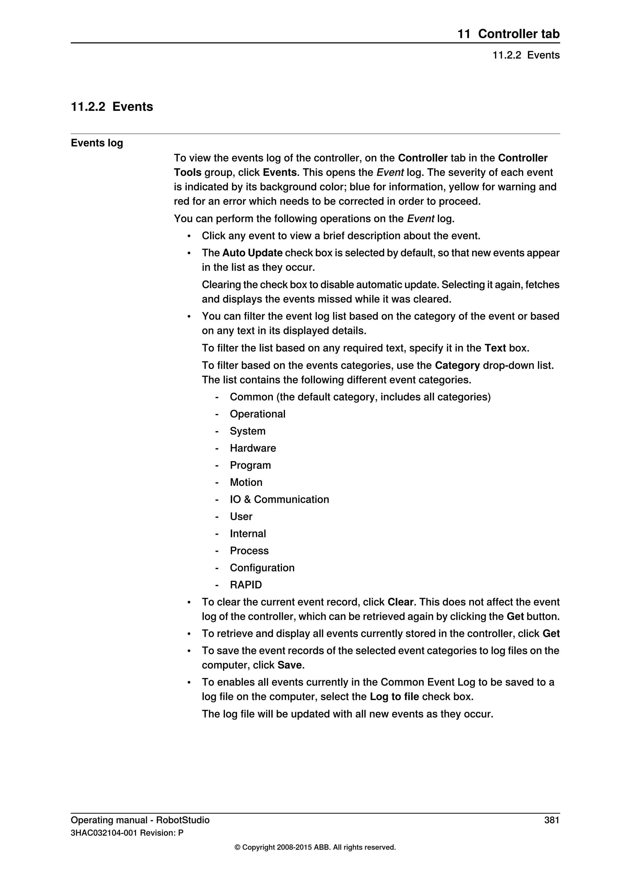
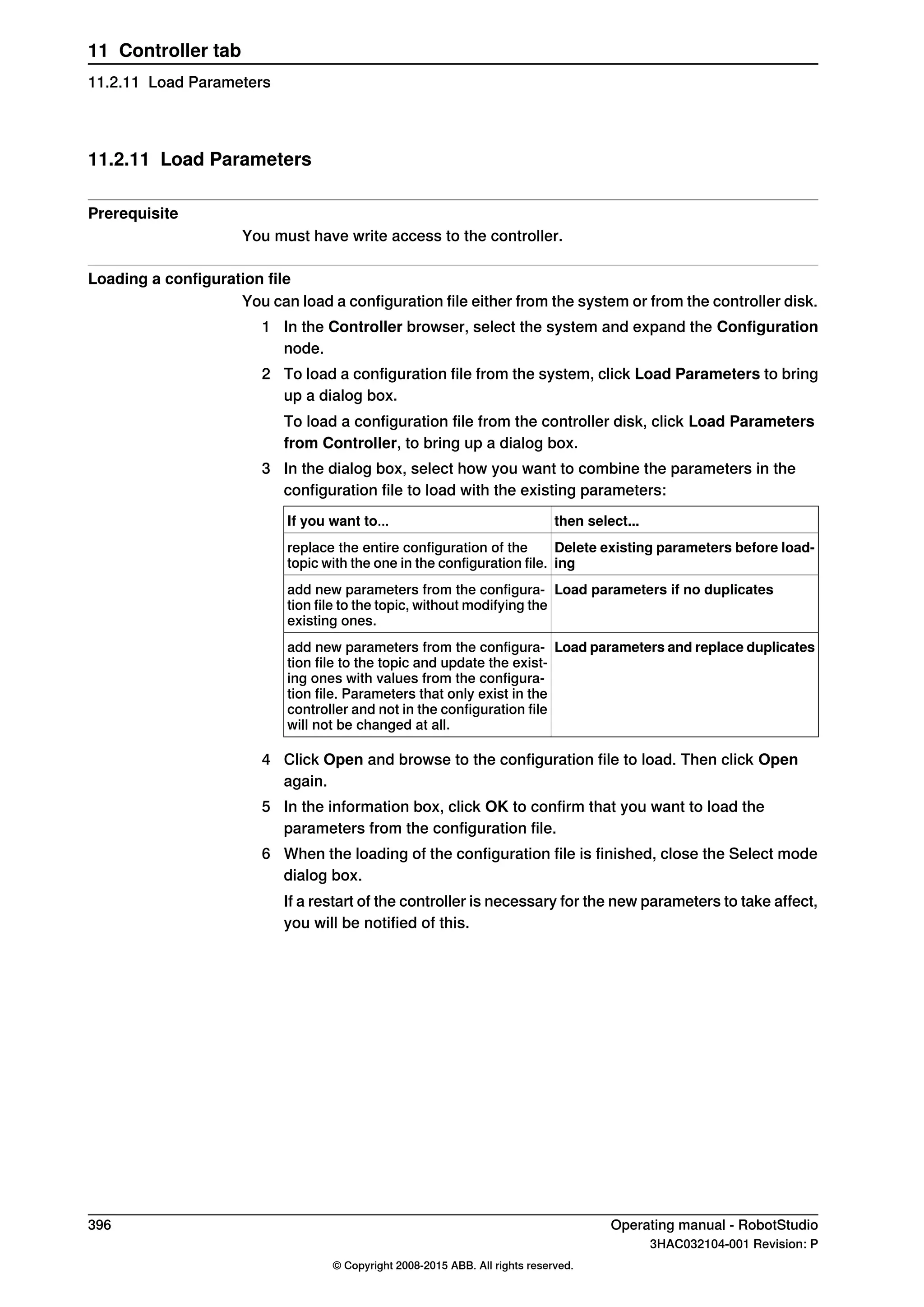
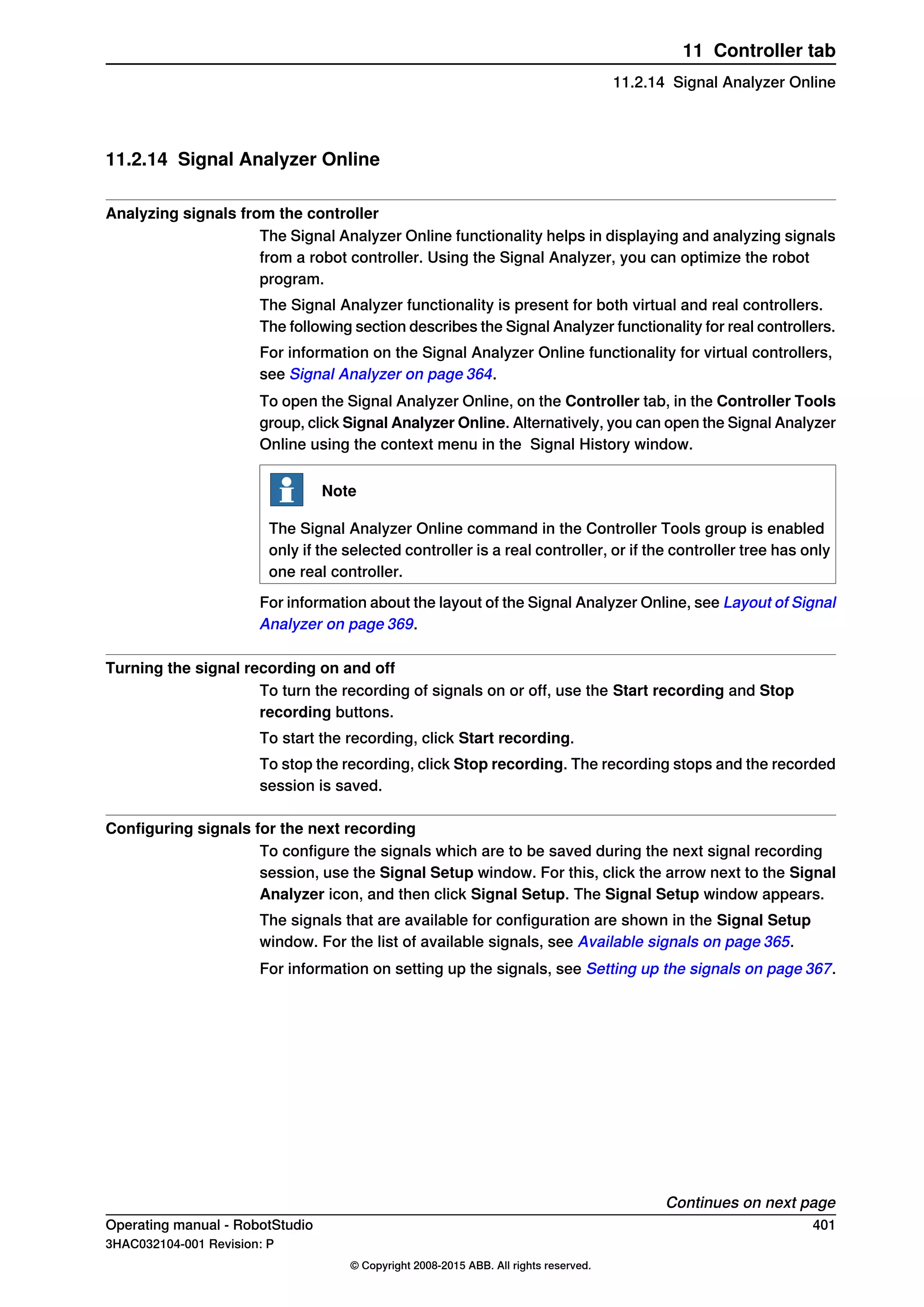
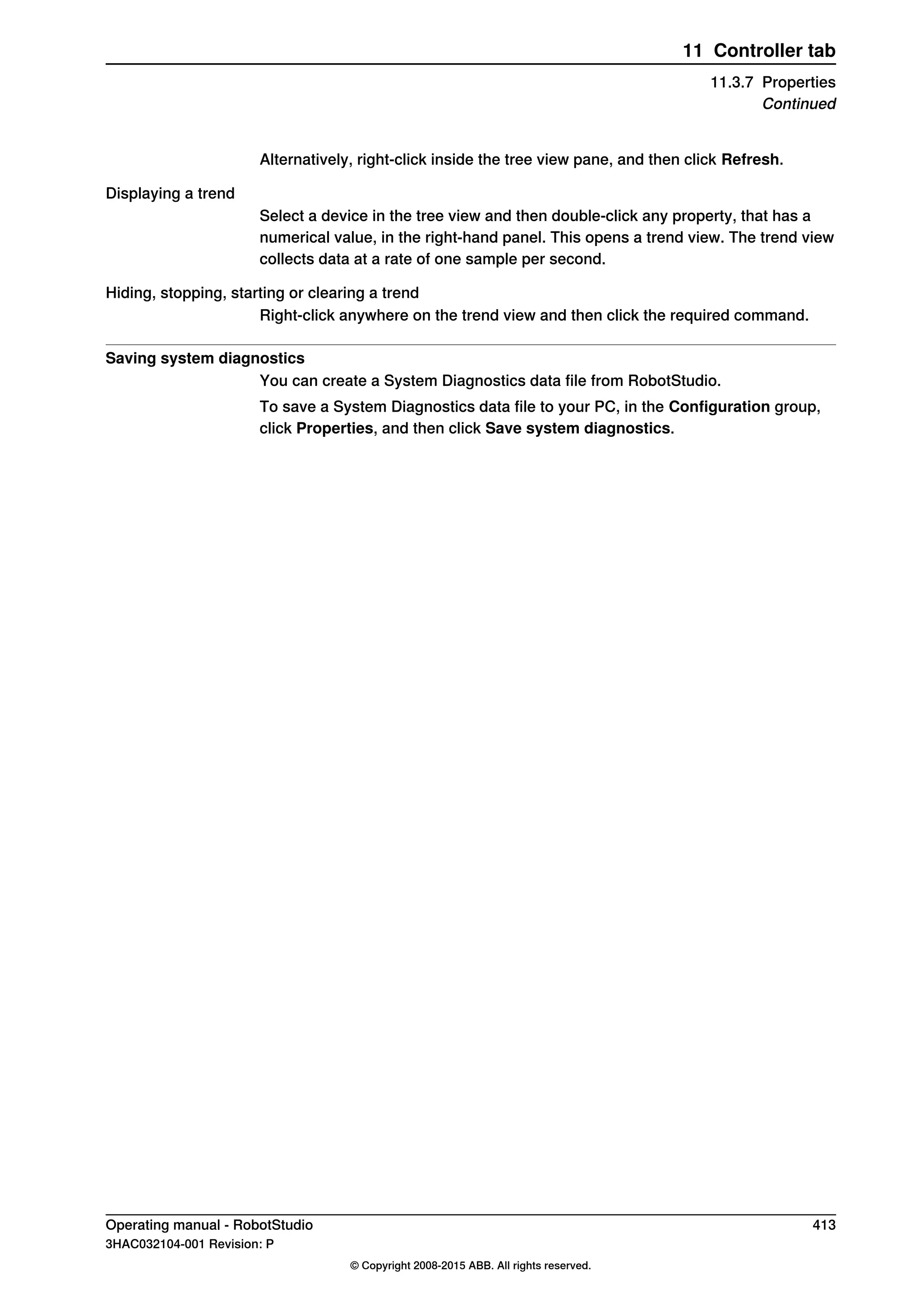
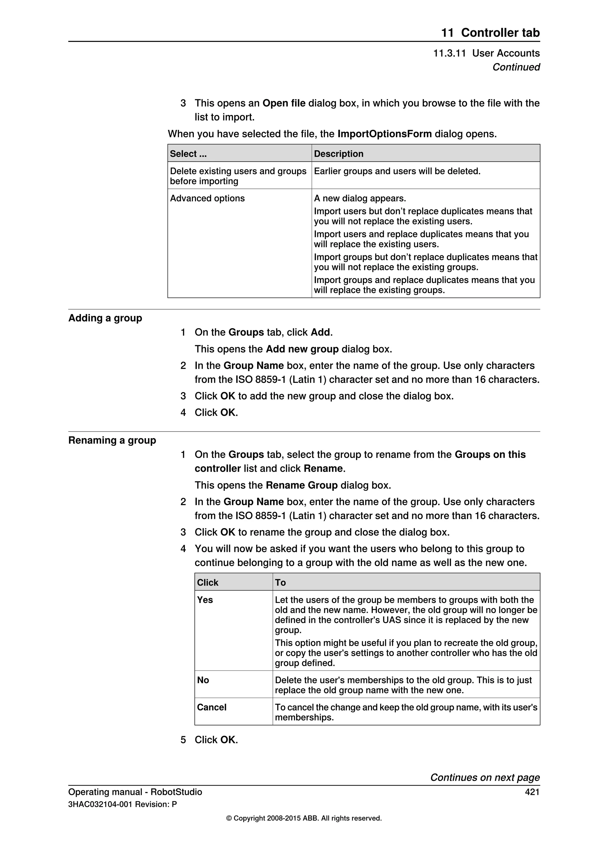
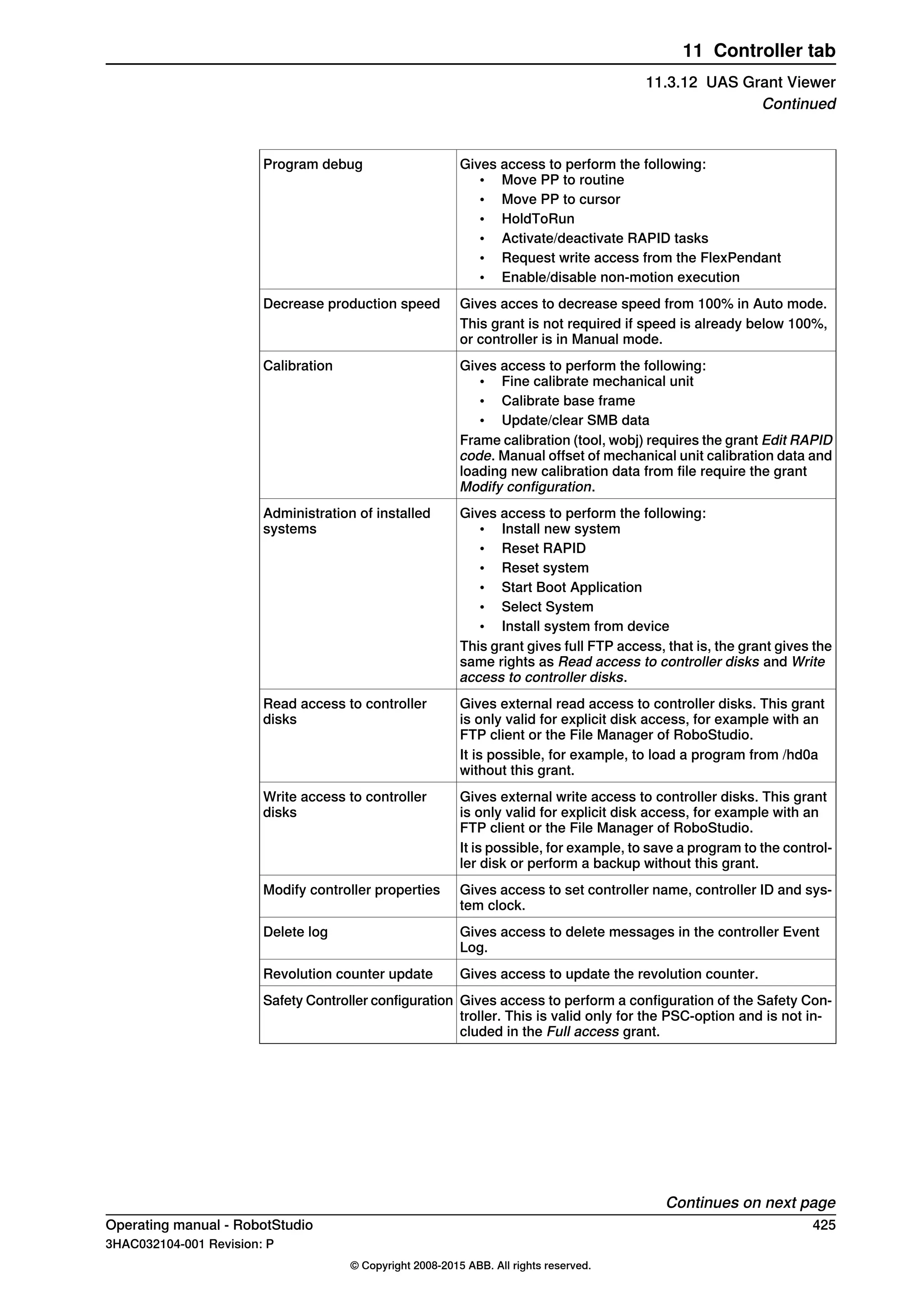
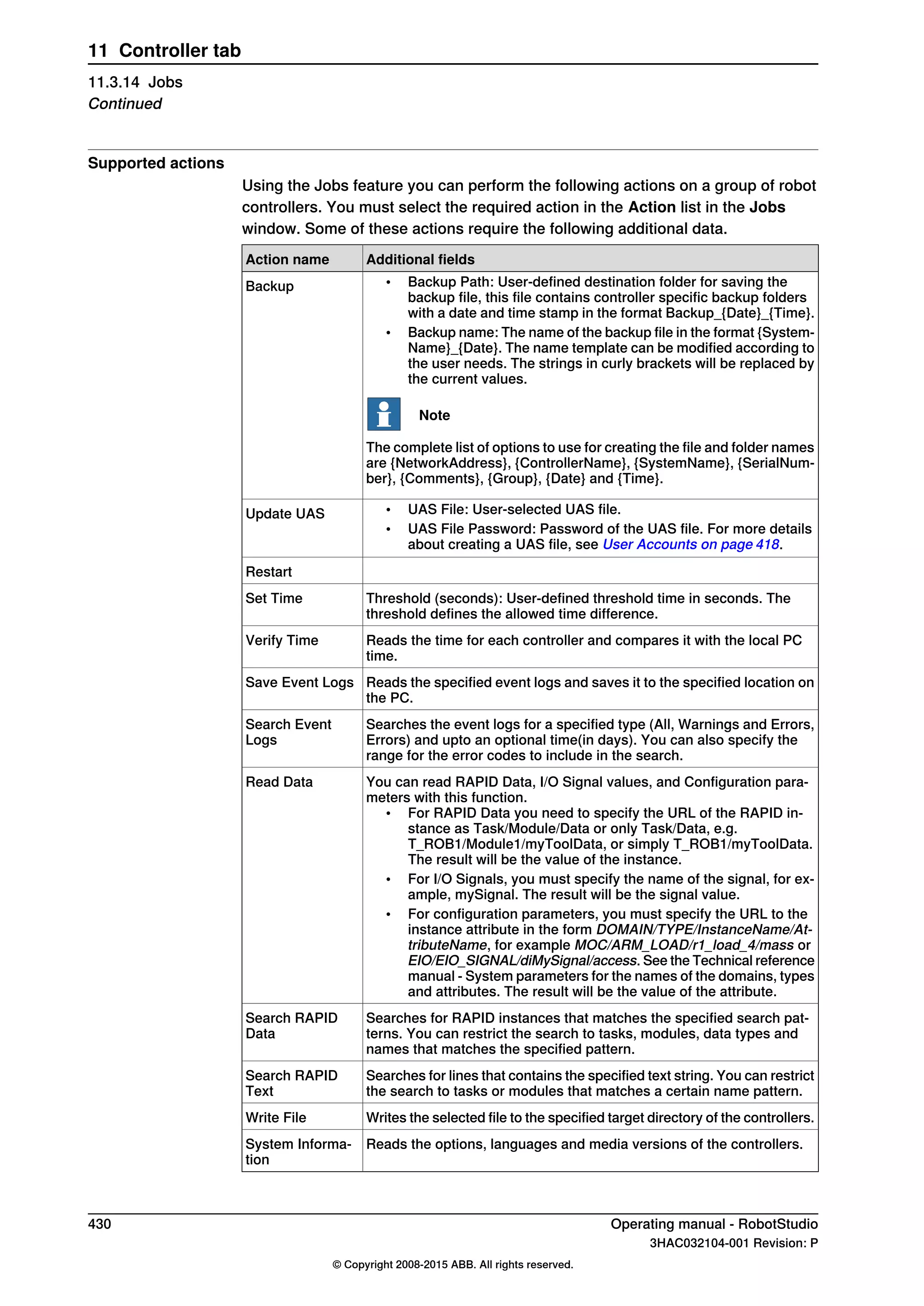
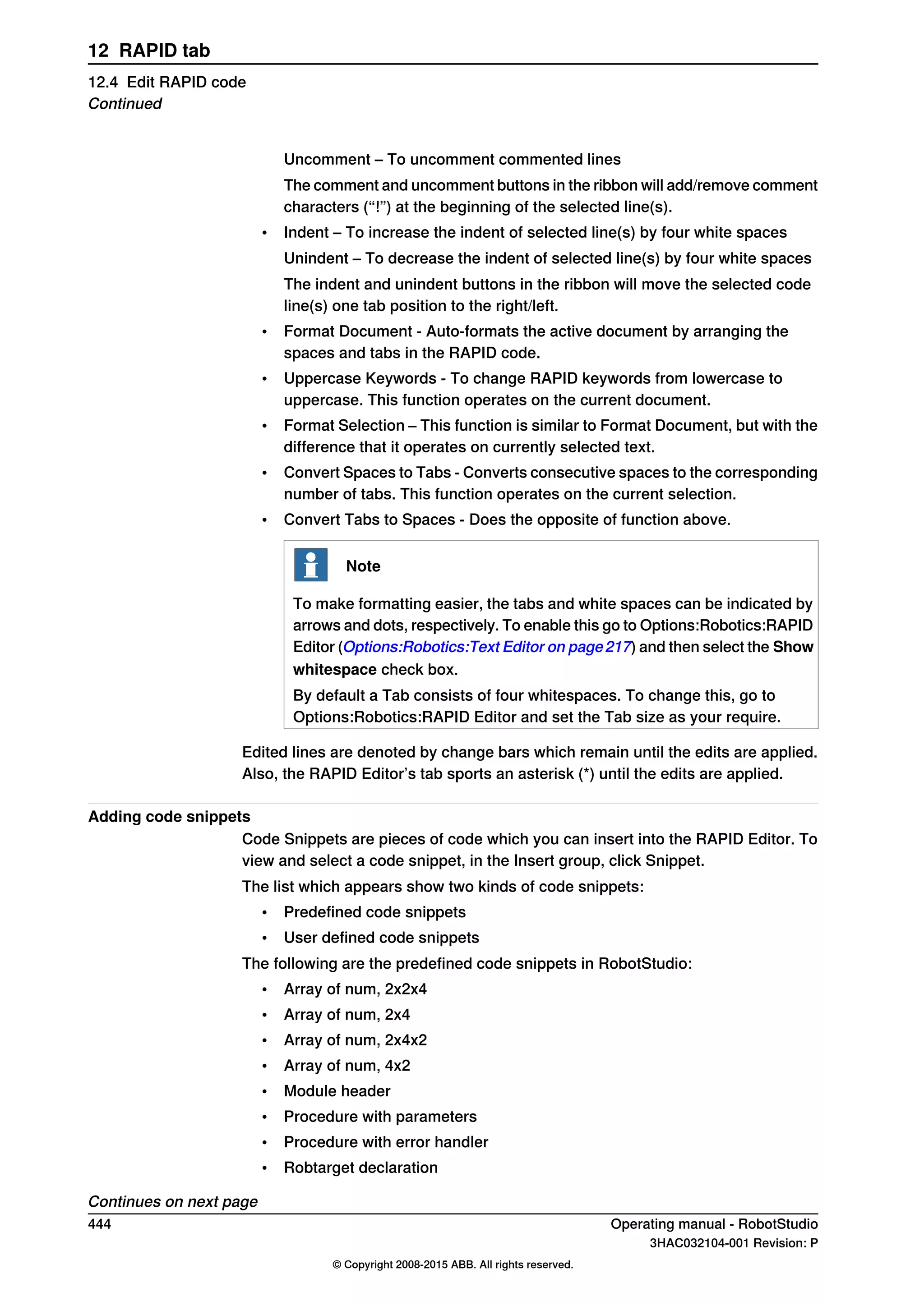
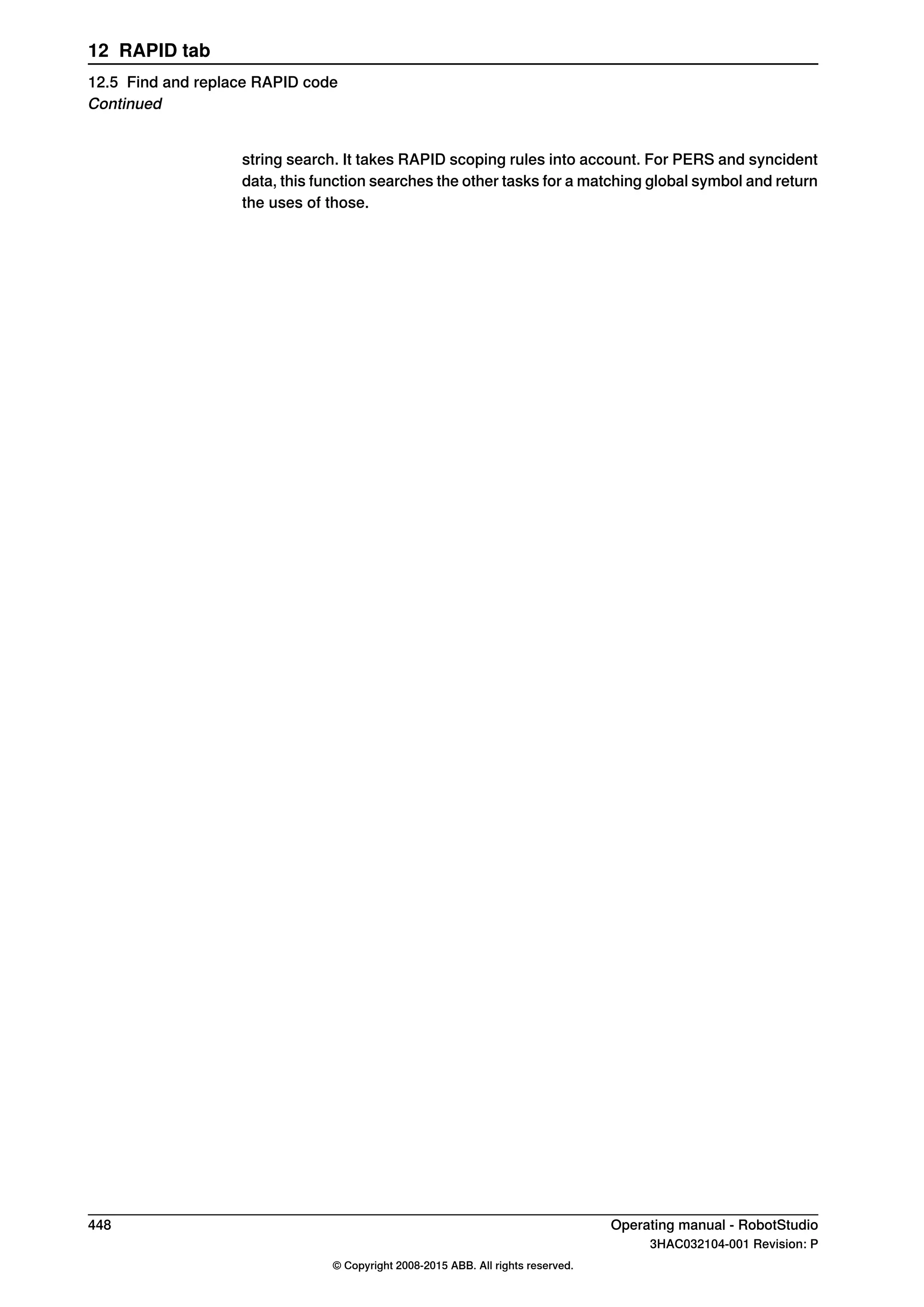
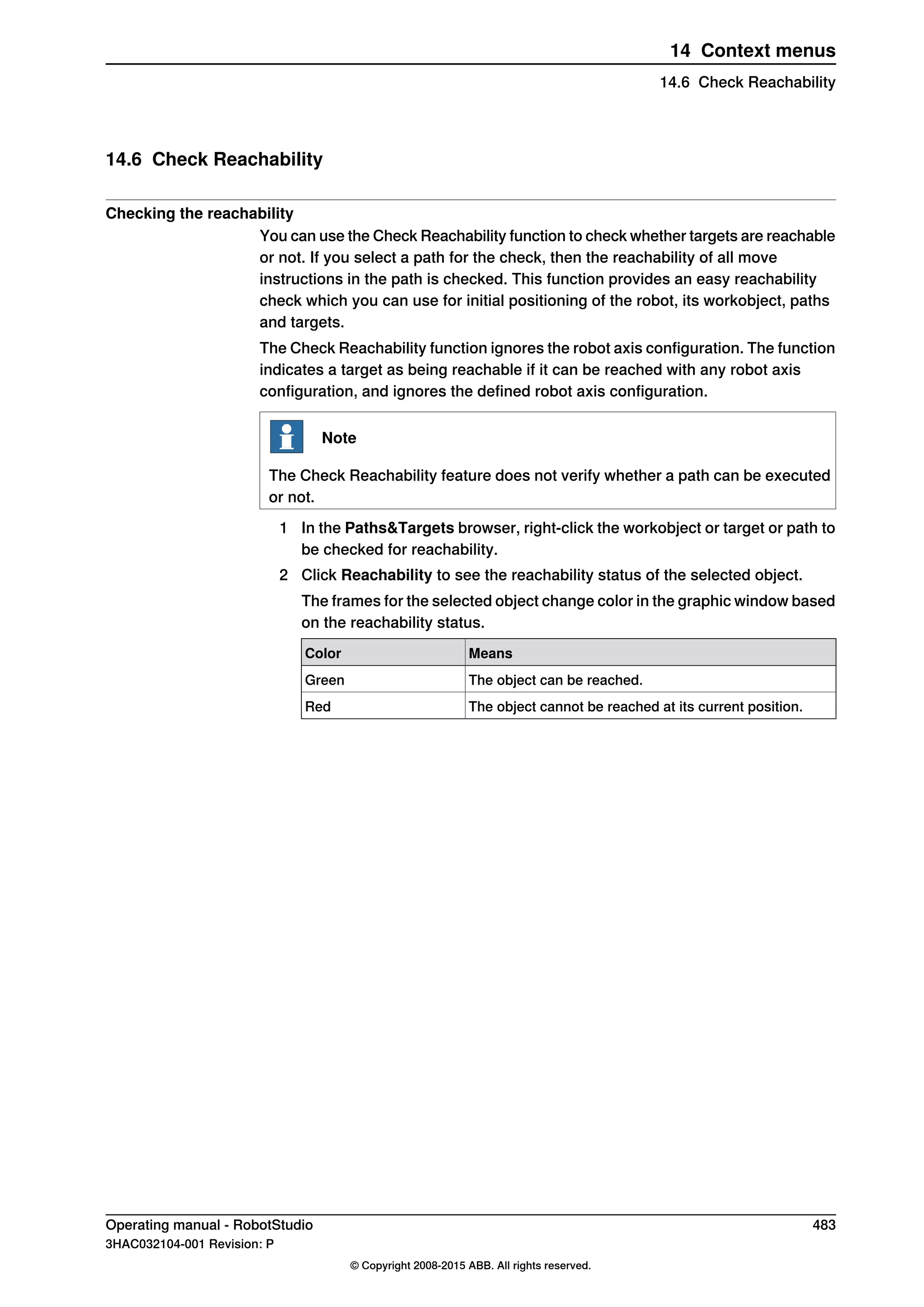
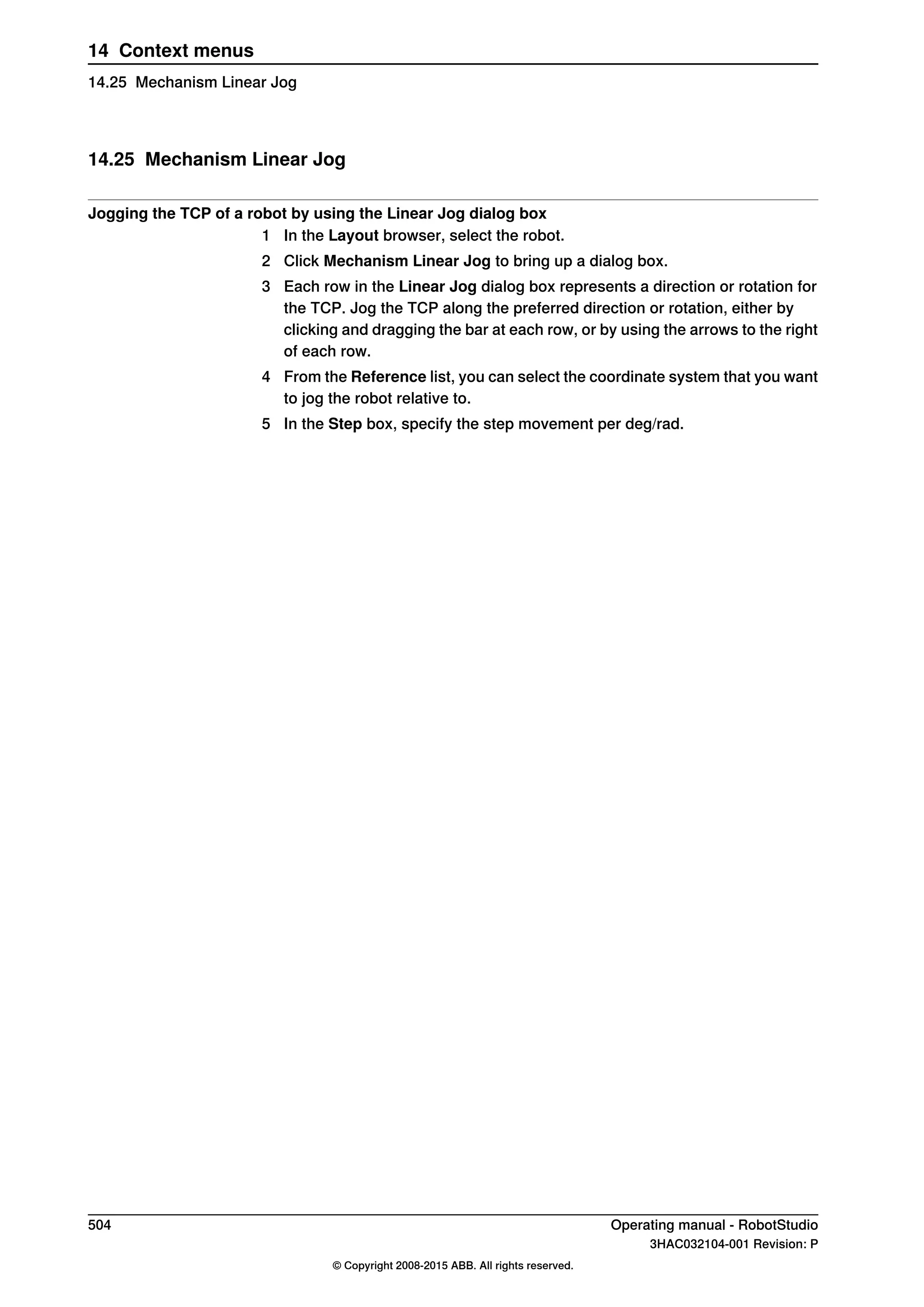
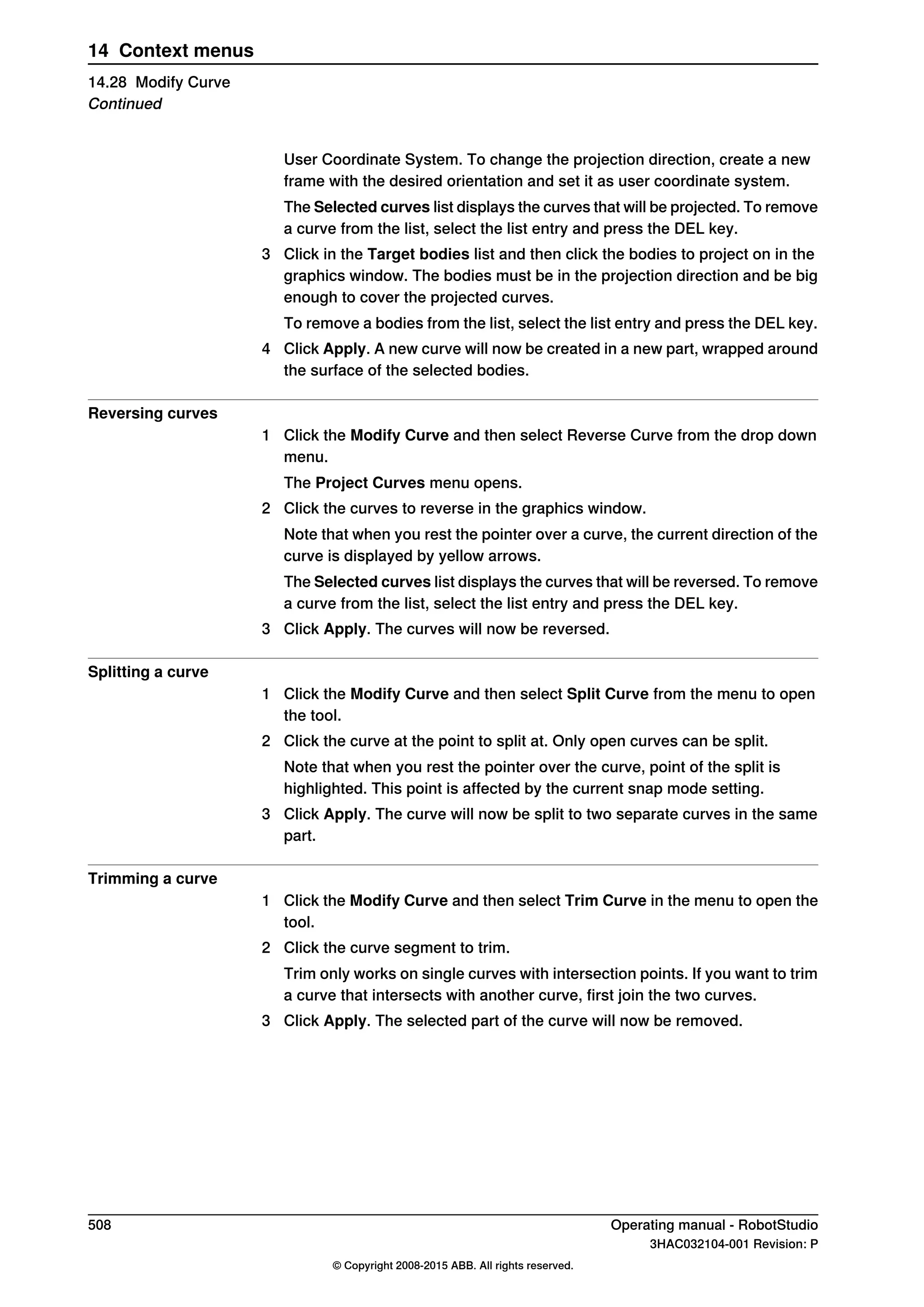
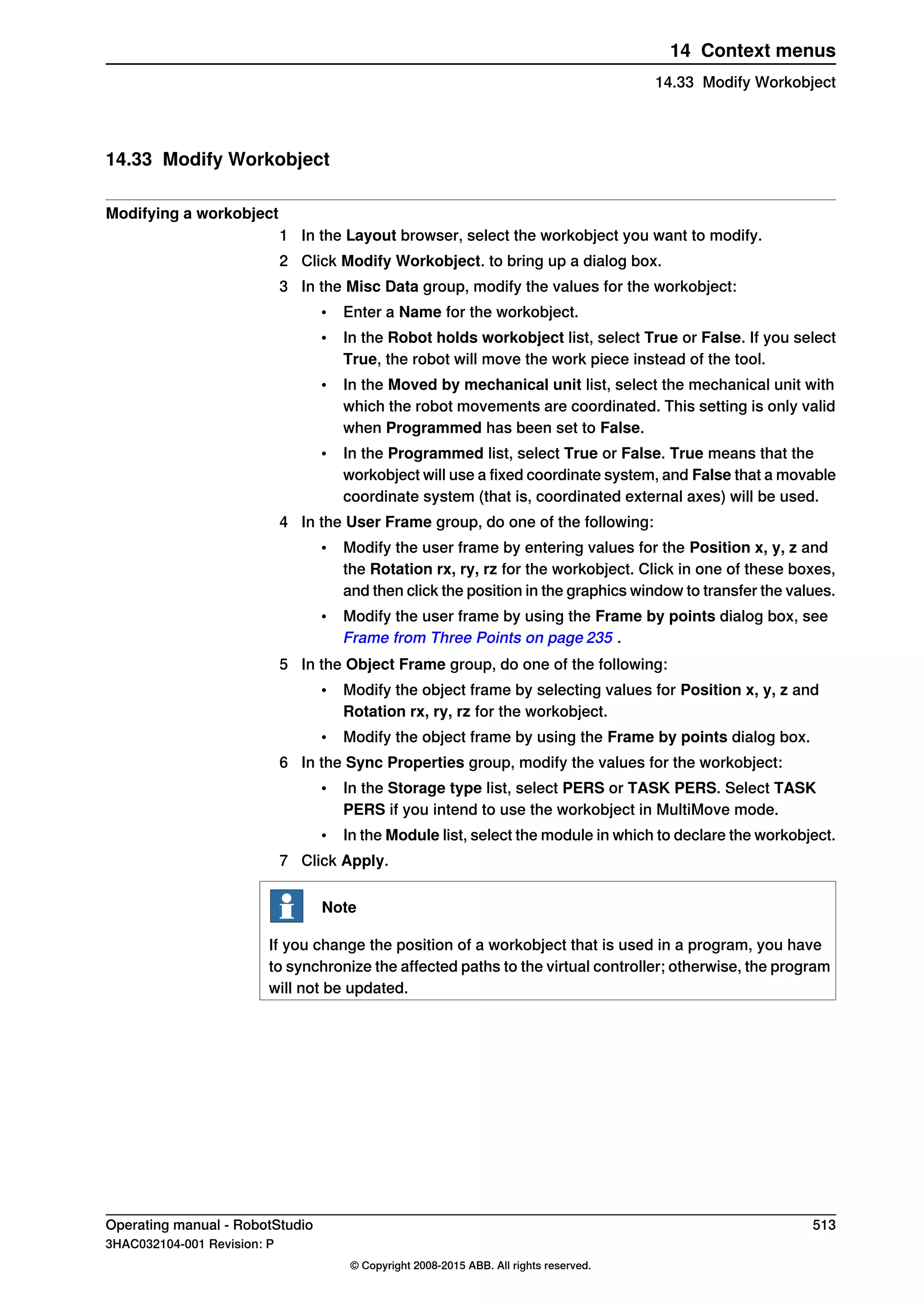
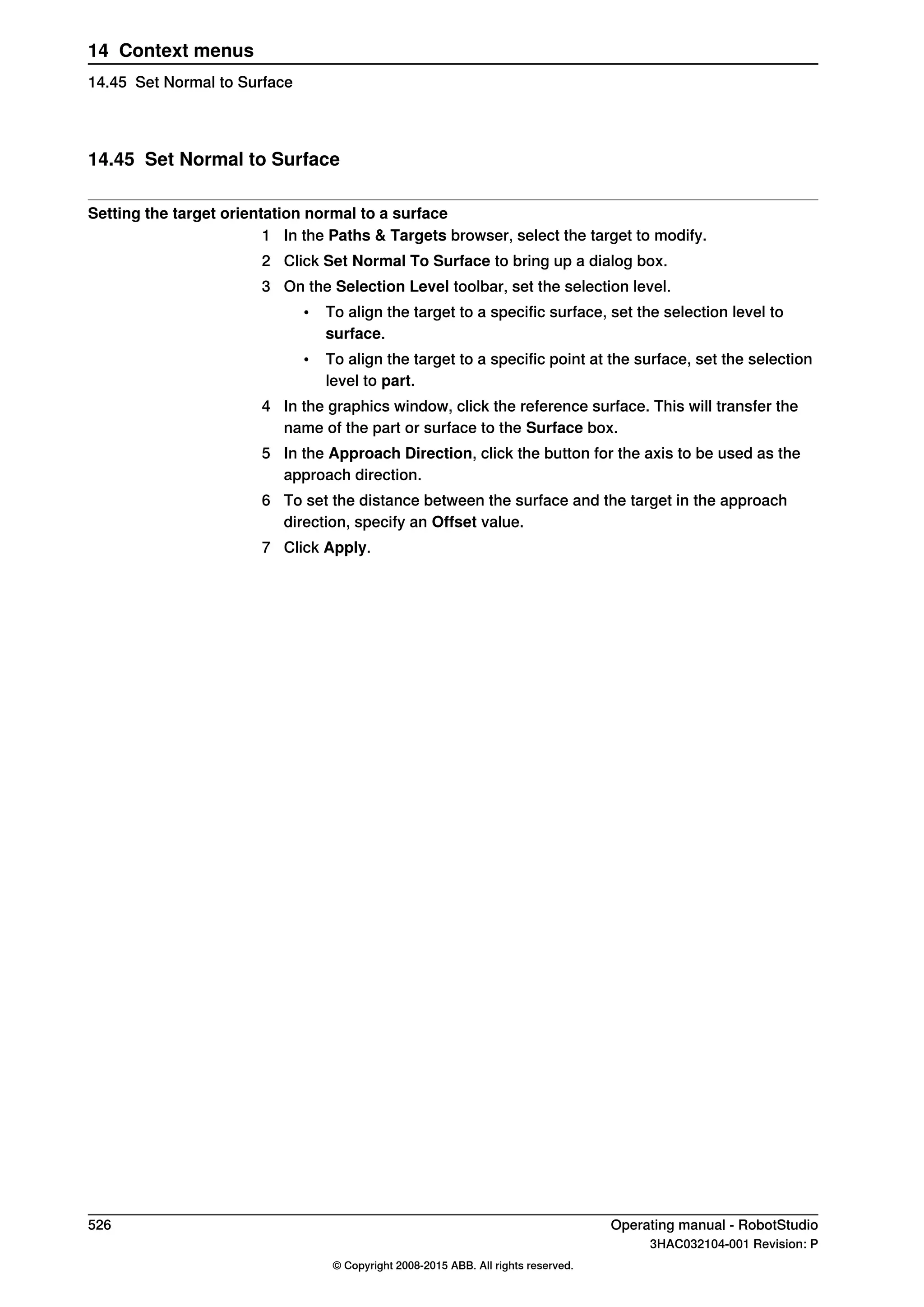
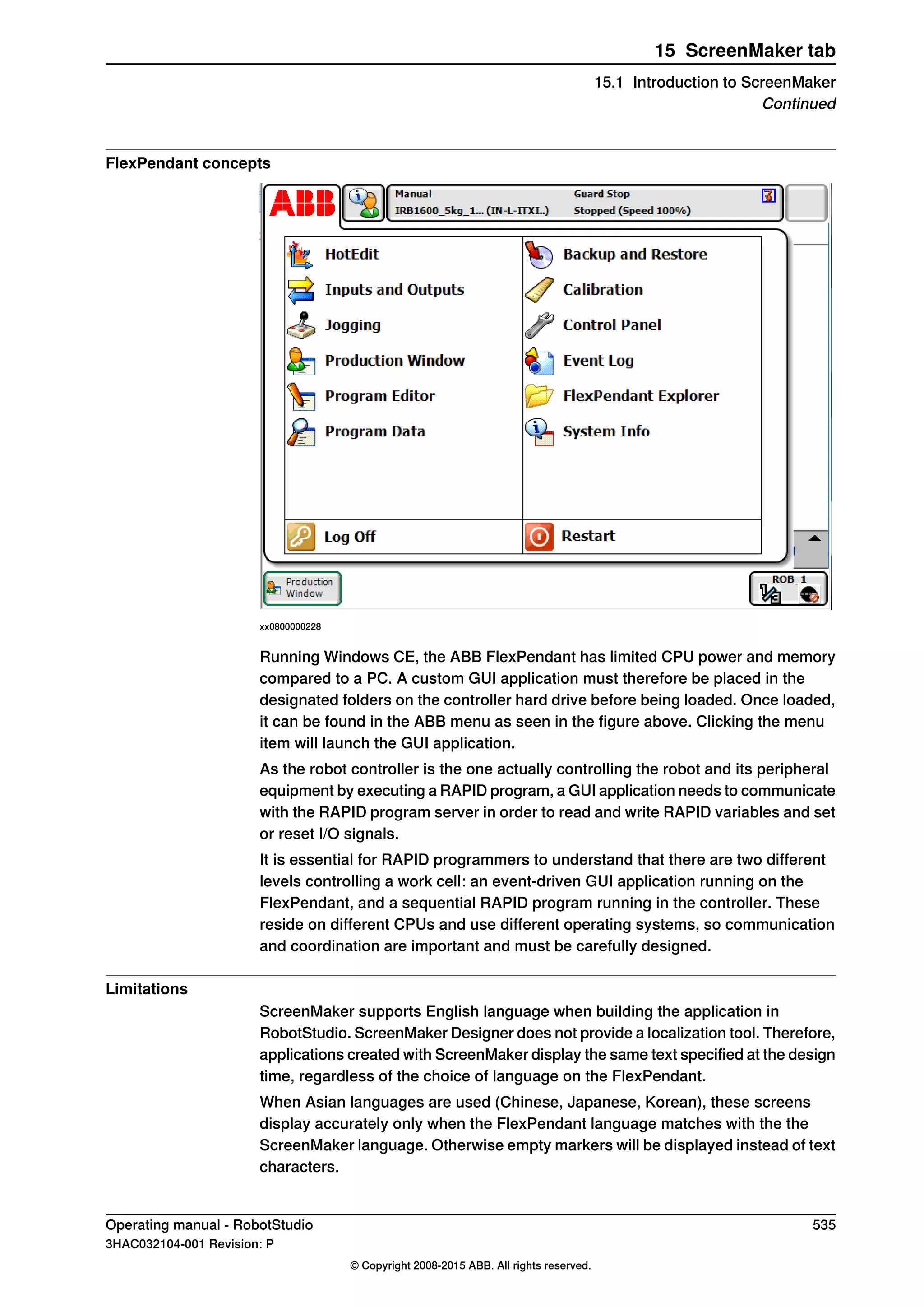
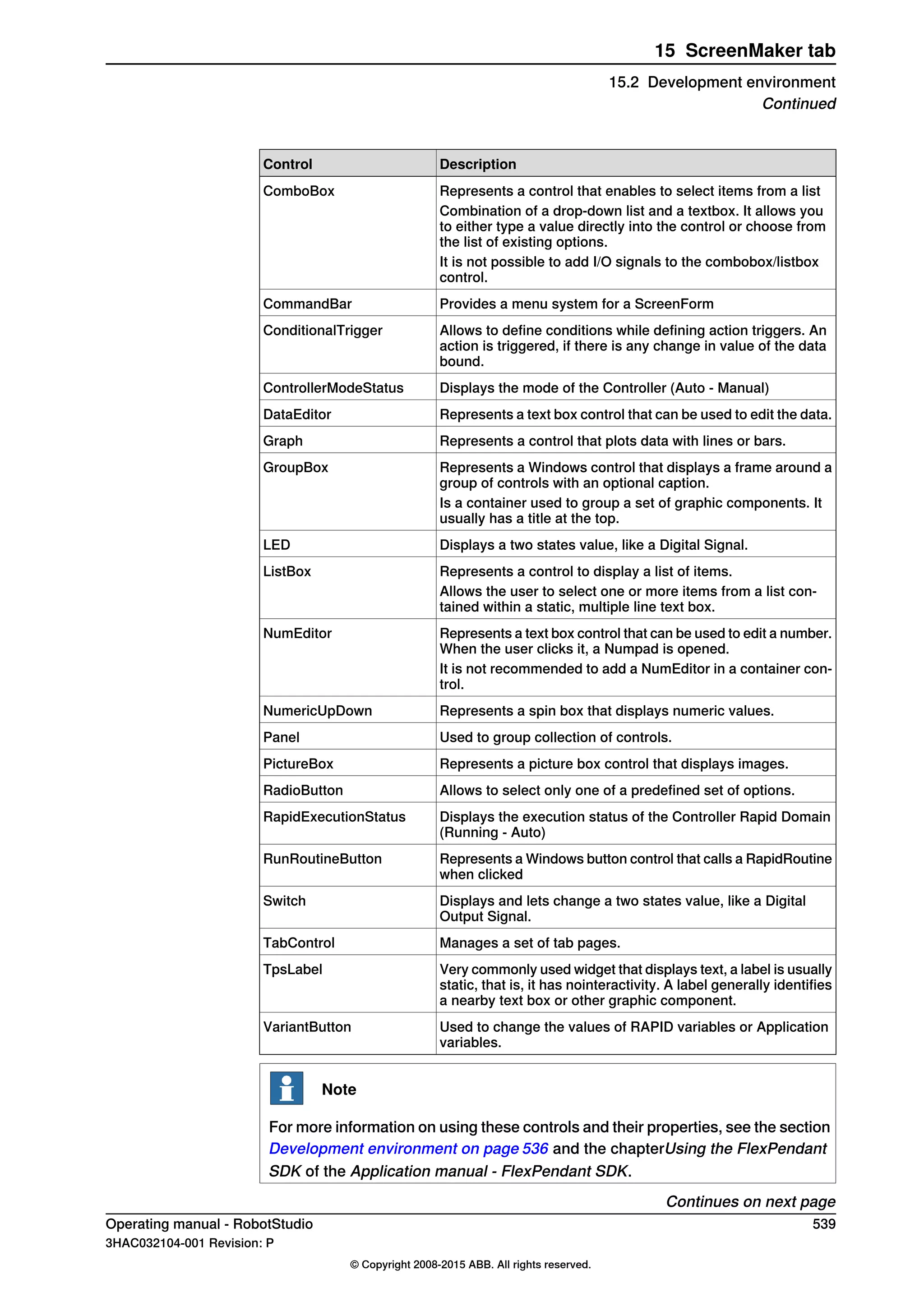
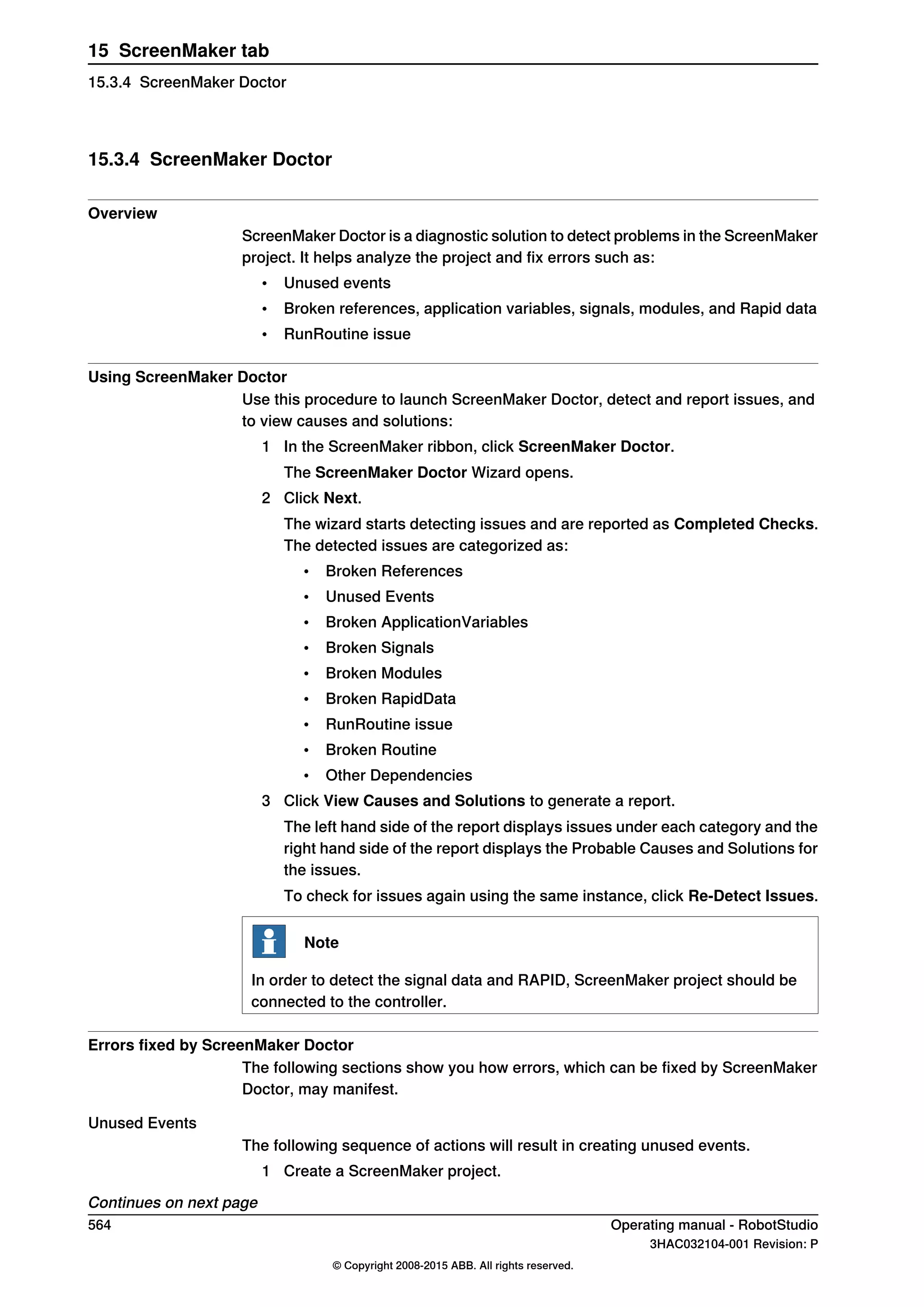
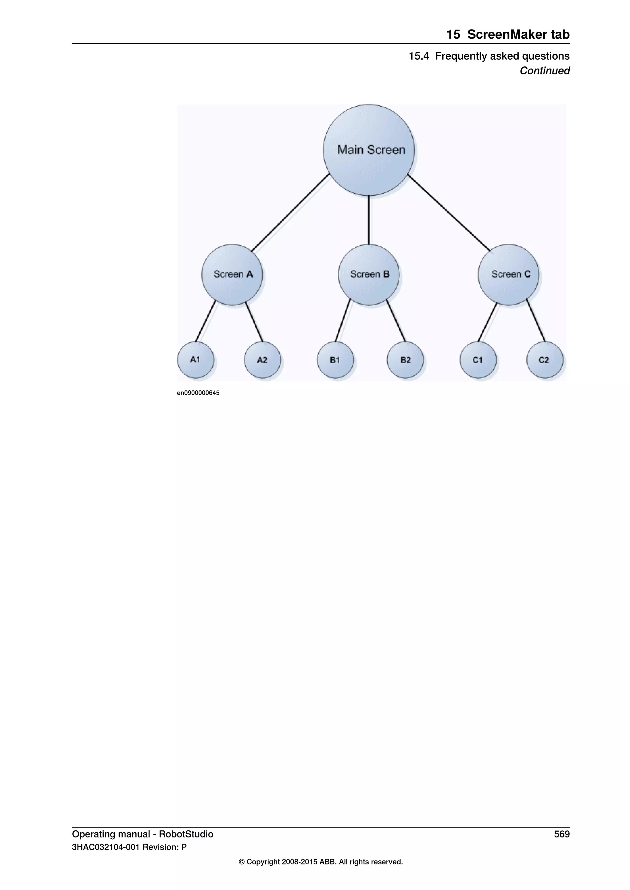
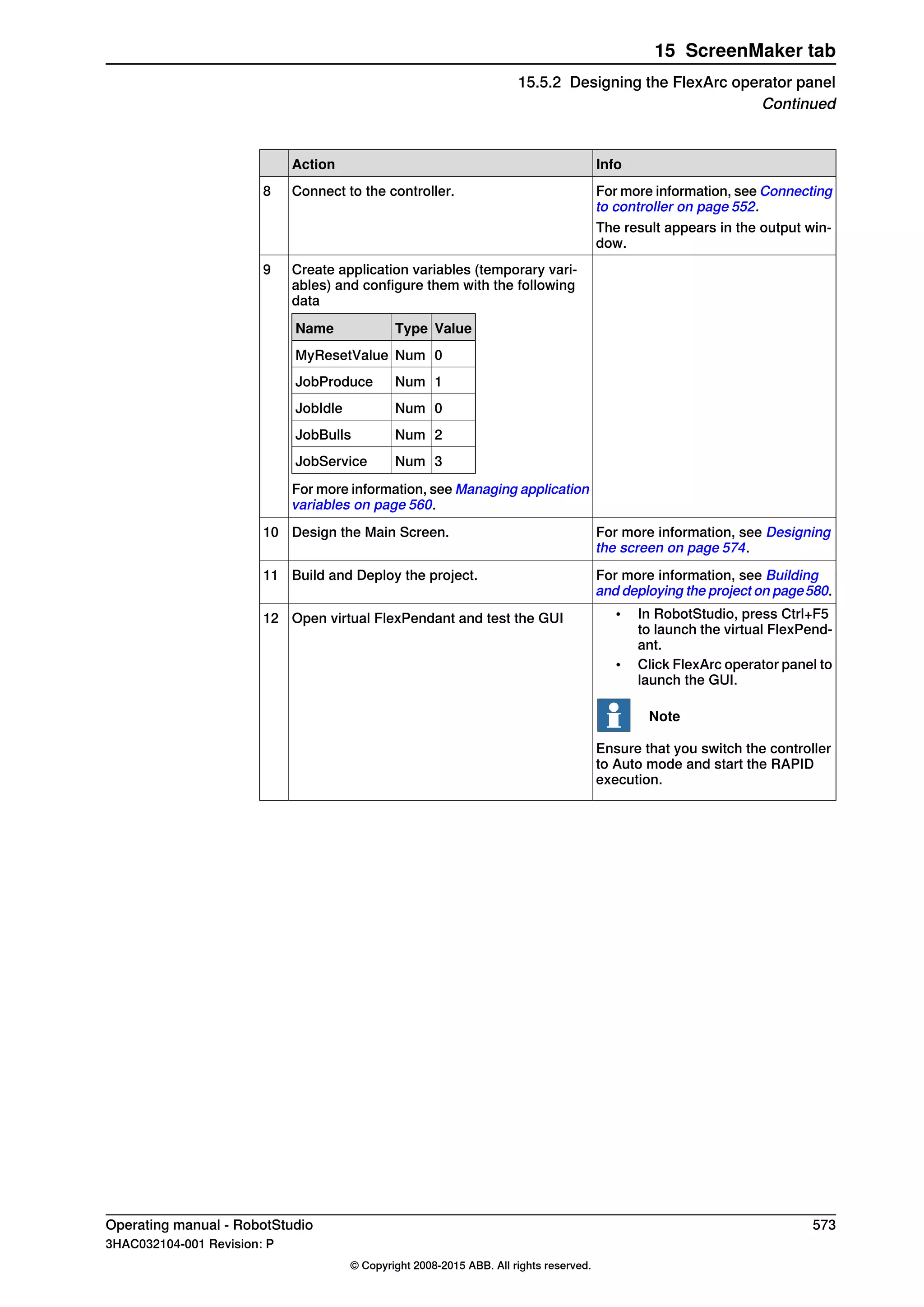
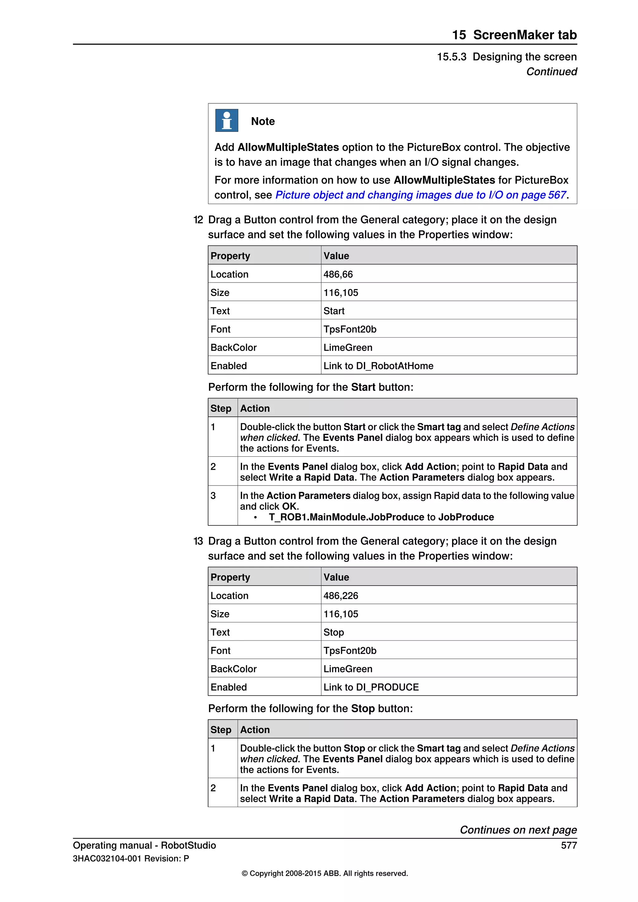
Screen navigation
Screen navigation in ScreenMaker follows a tree structure.
Consider the following example,
• To open screen A1, you first have to open Screen A
• To navigate from screen A1 to screen B1, you first have to close screen A1
and then Screen A and navigate from Main Screen through Screen B to
screen B1.
• Similarly, to navigate from screen B1 to screen C1, you first have to close
screen B1 and Screen B and then navigate from Main Screen through Screen
C to screen C1.
Continues on next page
568 Operating manual - RobotStudio
3HAC032104-001 Revision: P
© Copyright 2008-2015 ABB. All rights reserved.
15 ScreenMaker tab
15.4 Frequently asked questions
Continued](https://image.slidesharecdn.com/prog-150726124729-lva1-app6892/75/Prog-568-2048.jpg)


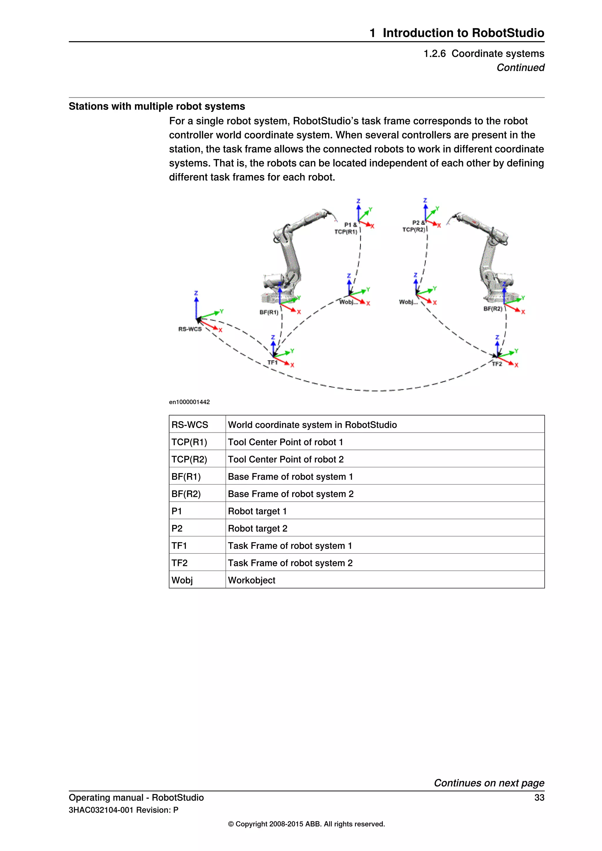
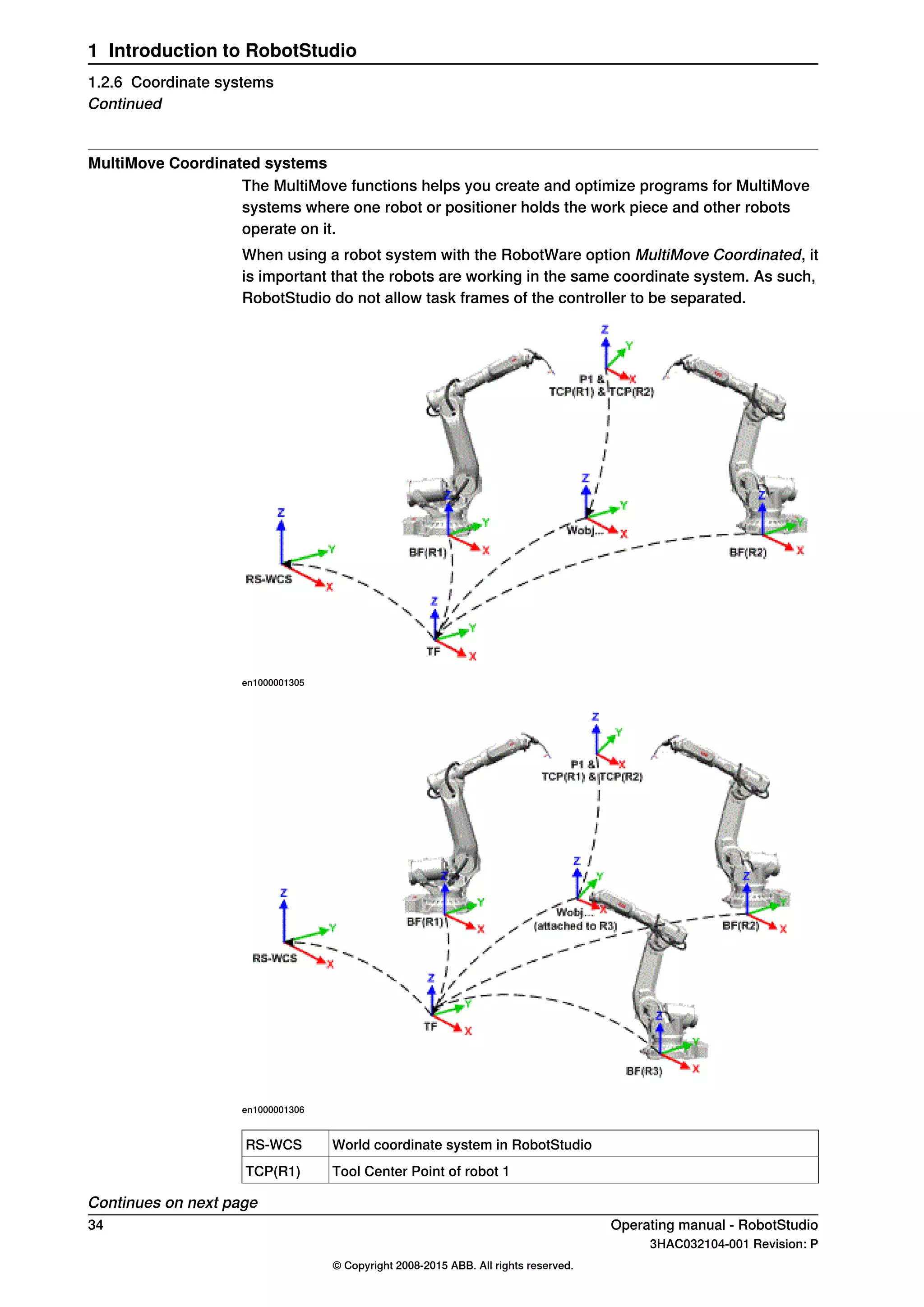
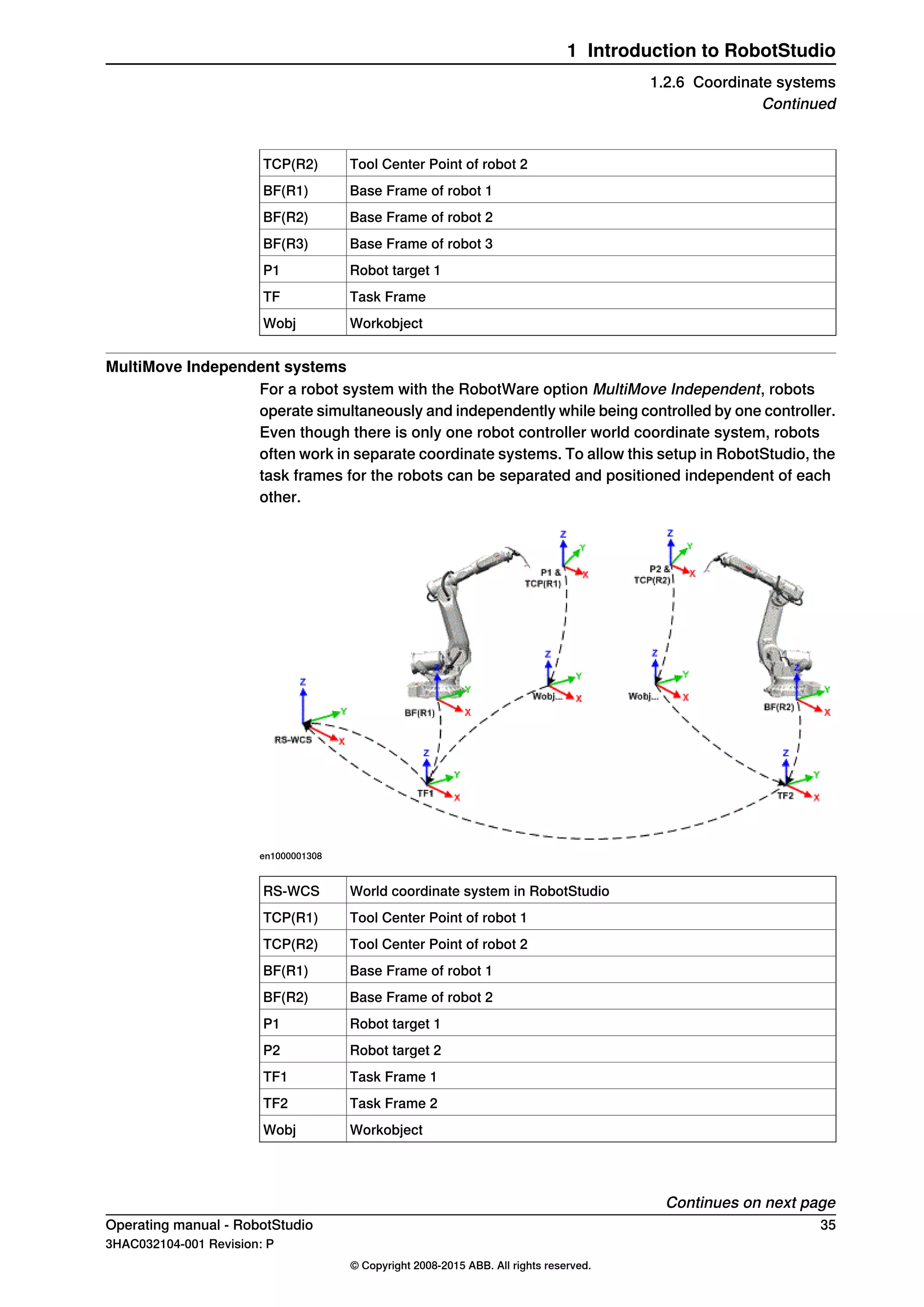
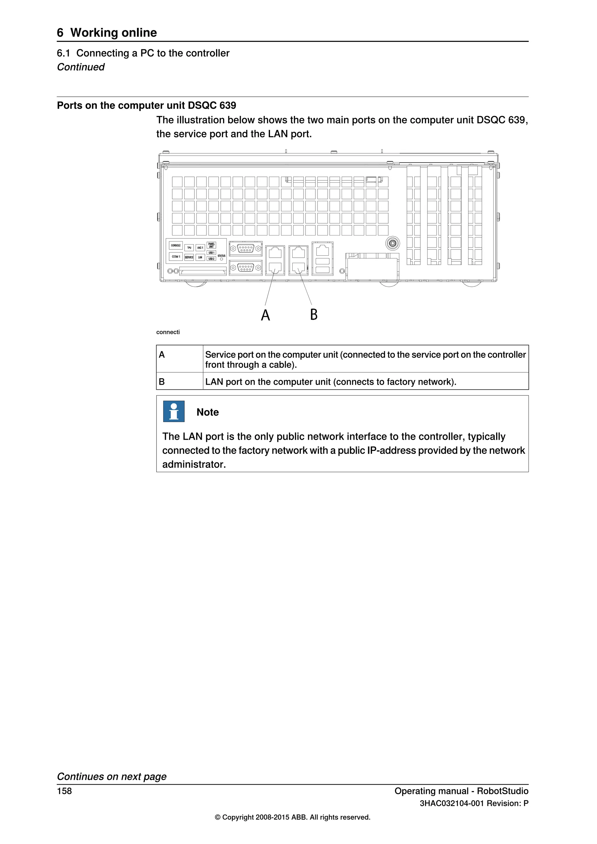
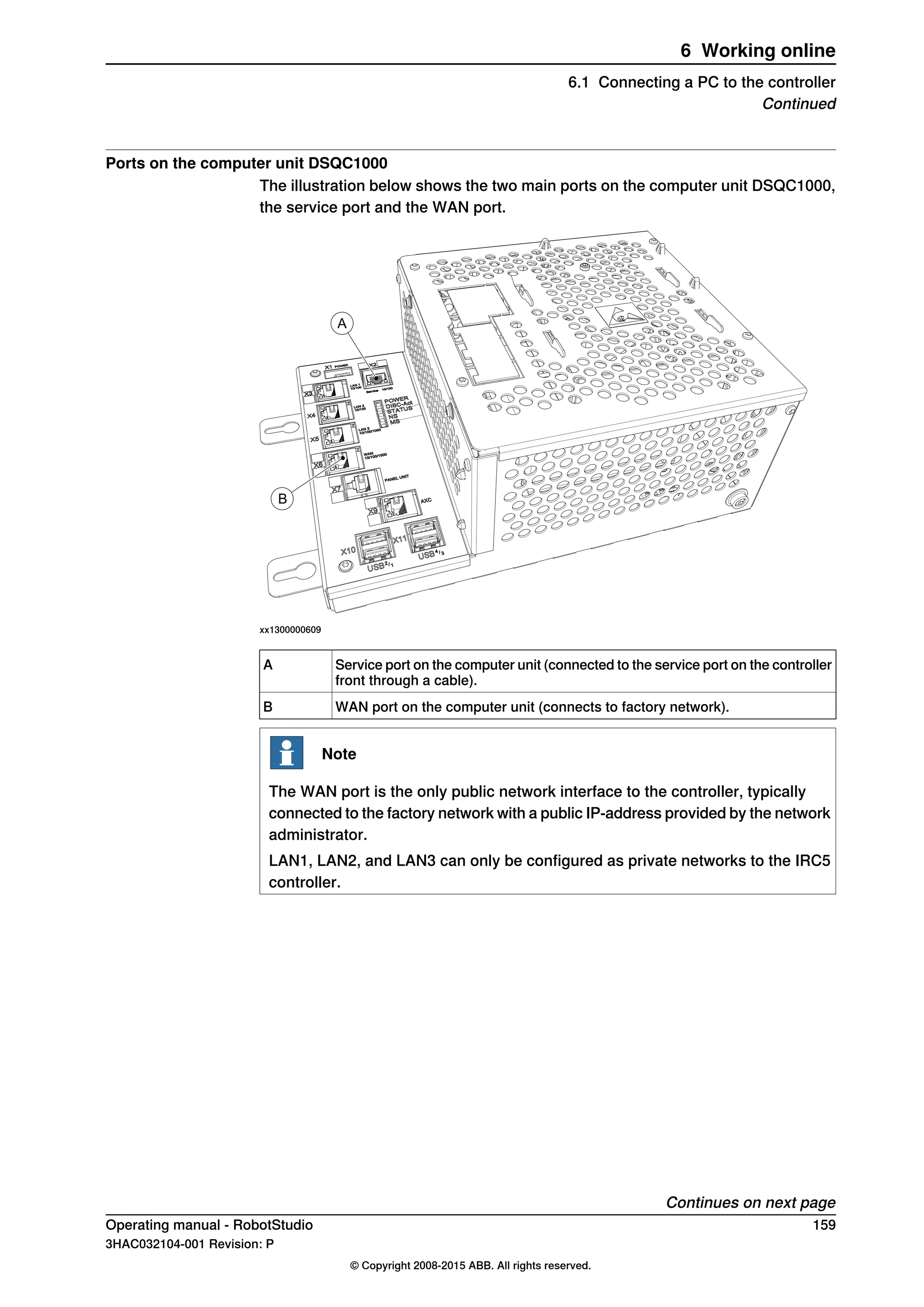
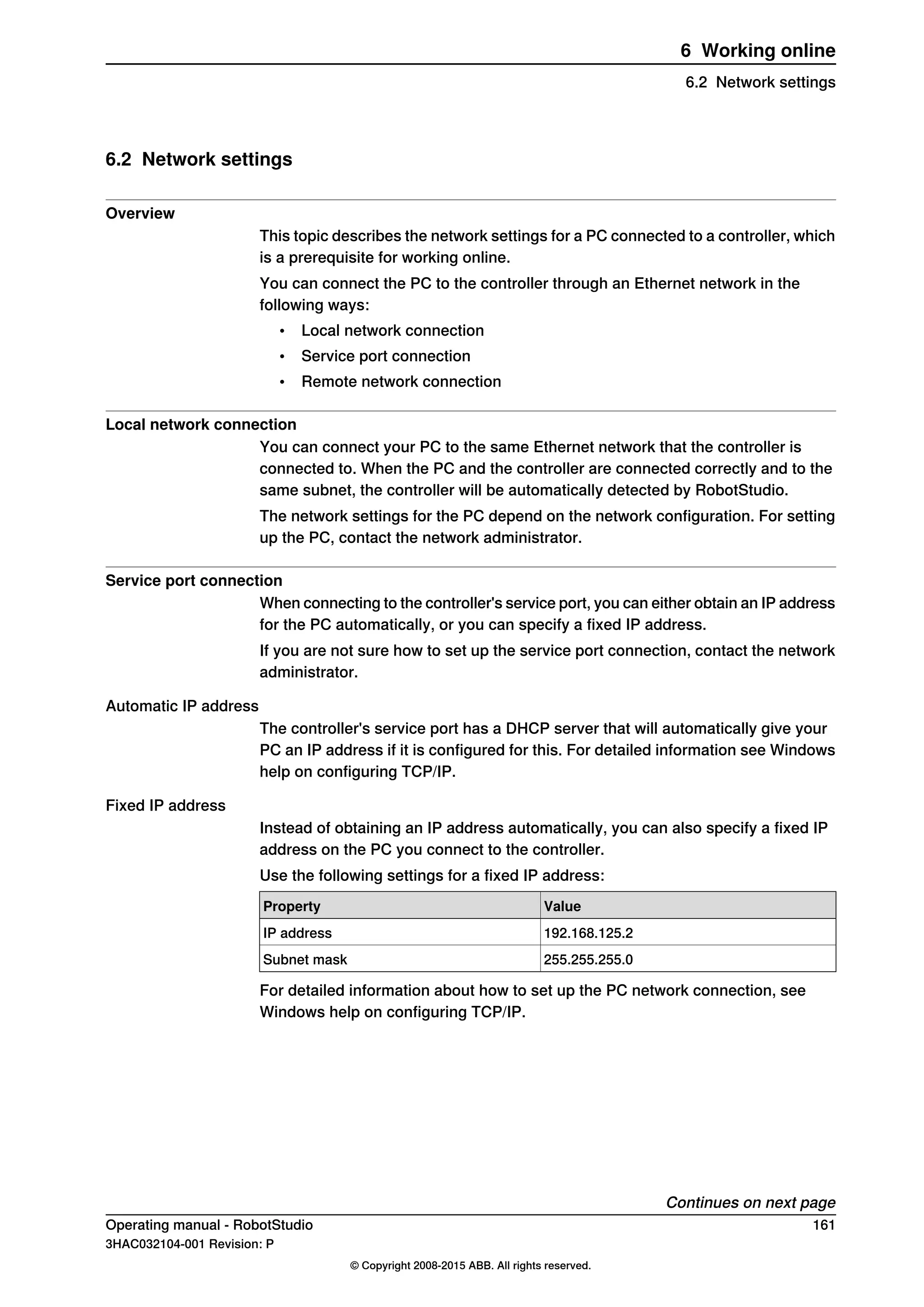
This document provides an overview of the RobotStudio operating manual. It includes sections on installing and licensing RobotStudio, the user interface, building robot stations, programming robots, deploying and distributing programs, simulating programs, working online with controllers, and using the different tabs in RobotStudio. The table of contents lists over 20 main sections and numerous subsections that comprise the full manual.


![Moho Pro 14.4 Crack for MacOS Works Until 2050 [Latest] pptx](https://cdn.slidesharecdn.com/ss_thumbnails/softwareoverview-251207192639-797289c4-thumbnail.jpg?width=640&height=640&fit=bounds)
![AnyTrans for iOS 8.9.14.20251127 With Crack for MacOS [Latest] pptx](https://cdn.slidesharecdn.com/ss_thumbnails/softwareoverview-251207190907-2316965f-thumbnail.jpg?width=640&height=640&fit=bounds)

![iStat Menus 7.20 Crack for MacOS 2026 Full Version [Latest] pptx](https://cdn.slidesharecdn.com/ss_thumbnails/softwareoverview-251207191544-22b737dc-thumbnail.jpg?width=640&height=640&fit=bounds)


![Chapter4_Initiation_of_Sediment_Motion_v2[1].pptx](https://cdn.slidesharecdn.com/ss_thumbnails/chapter4initiationofsedimentmotionv21-251208223747-f94ef163-thumbnail.jpg?width=640&height=640&fit=bounds)

![WinRAR Crack 7.13 Final Mac Keygen 2026 Download [Latest] Software.pptx](https://cdn.slidesharecdn.com/ss_thumbnails/software-251207185858-eb450678-thumbnail.jpg?width=640&height=640&fit=bounds)

![Soundtoys Mac v5.5.5.0 Crack for MacOS Full Version [Latest] pptx](https://cdn.slidesharecdn.com/ss_thumbnails/softwareoverview-251207193711-91d8ae6b-thumbnail.jpg?width=640&height=640&fit=bounds)

![PowerISO 9.2 Mac Crack + Serial Key Free Download 2026 [Latest] Software.pptx](https://cdn.slidesharecdn.com/ss_thumbnails/software-251207185653-5d5700e6-thumbnail.jpg?width=640&height=640&fit=bounds)


