Unit – 3:Entity-Relationship Model 2
Topics to be covered
• Basic concepts
• Design process
• Constraints and keys
• Design issues
• E-R diagrams
• Weak entity sets
• Extended E-R features
• Generalization and Specialization
• Aggregation
• Reduction to E-R database schema
3.
Unit – 3:Entity-Relationship Model 3
What is Database Design?
Database Design is a collection of processes that facilitate the
designing, development, implementation and maintenance of
enterprise database management systems.
4.
Unit – 3:Entity-Relationship Model 4
What is E-R diagram?
E-R diagram: (Entity-Relationship diagram)
It is graphical (pictorial) representation of database.
It uses different types of symbols to represent different objects of
database.
5.
Unit – 3:Entity-Relationship Model 5
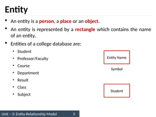
Entity
An entity is a person, a place or an object.
An entity is represented by a rectangle which contains the name
of an entity.
Entities of a college database are:
• Student
• Professor/Faculty
• Course
• Department
• Result
• Class
• Subject
Entity Name
Symbol
Student
6.
Unit – 2:Relational Model 6
1. Write down the different entities of bank database.
2. Write down the different entities of hospital database.
Exercise
7.
Unit – 3:Entity-Relationship Model 7
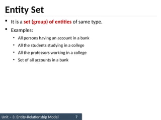
Entity Set
It is a set (group) of entities of same type.
Examples:
• All persons having an account in a bank
• All the students studying in a college
• All the professors working in a college
• Set of all accounts in a bank
8.
Unit – 3:Entity-Relationship Model 8
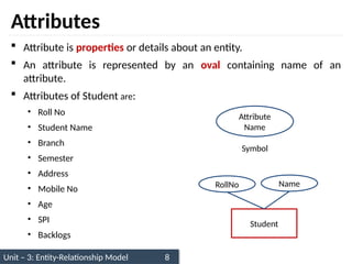
Attributes
Attribute is properties or details about an entity.
An attribute is represented by an oval containing name of an
attribute.
Attributes of Student are:
• Roll No
• Student Name
• Branch
• Semester
• Address
• Mobile No
• Age
• SPI
• Backlogs
Symbol
Attribute
Name
Student
RollNo Name
9.
Unit – 2:Relational Model 9
1. Write down the attributes of Faculty.
2. Write down the attributes of Account.
Exercise
10.
Unit – 3:Entity-Relationship Model 10
Relationship
Relationship is an association (connection) between several
entities.
It should be placed between two entities and a line connecting it
to an entity.
A relationship is represented by a diamond containing
relationship's name.
Relationship
Name
Symbol
Student Book
Issue
11.
Unit – 3:Entity-Relationship Model 11
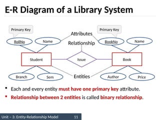
E-R Diagram of a Library System
Each and every entity must have one primary key attribute.
Relationship between 2 entities is called binary relationship.
Student Book
Issue
RollNo Name
Branch Sem
BookNo Name
Author Price
Primary Key Primary Key
Entities
Attributes
Relationship
12.
Unit – 3:Entity-Relationship Model 12
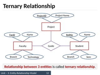
Ternary Relationship
Faculty Student
Guide
FacID Name
Branch Technology
RollNo Name
Branch Sem
Project
ProjectID Project Name
Relationship between 3 entities is called ternary relationship.
13.
Unit – 2:Relational Model 13
1. Draw E-R diagram of following pair of entities
i. Customer & Account
ii. Customer & Loan
iii. Doctor & Patient
Exercise
14.
Unit – 3:Entity-Relationship Model 14
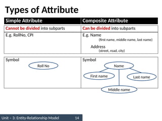
Types of Attribute
Simple Attribute Composite Attribute
Cannot be divided into subparts Can be divided into subparts
E.g. RollNo, CPI E.g. Name
(first name, middle name, last name)
Address
(street, road, city)
Symbol Symbol
Name
First name Last name
Roll No
Middle name
15.
Unit – 3:Entity-Relationship Model 15
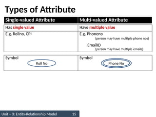
Types of Attribute
Single-valued Attribute Multi-valued Attribute
Has single value Have multiple value
E.g. Rollno, CPI E.g. Phoneno
(person may have multiple phone nos)
EmailID
(person may have multiple emails)
Symbol Symbol
Roll No Phone No
16.
Unit – 3:Entity-Relationship Model 16
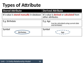
Types of Attribute
Stored Attribute Derived Attribute
It’s value is stored manually in database It’s value is derived or calculated from
other attributes.
E.g. Birthdate E.g. Age
(can be calculated using current date
and birthdate)
Symbol Symbol
Birthdate Age
17.
Unit – 3:Entity-Relationship Model 17
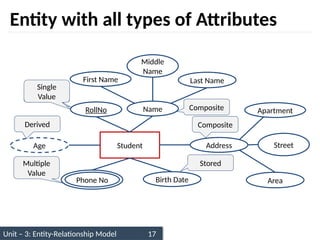
Entity with all types of Attributes
Student
RollNo Name
Phone No Birth Date
First Name Last Name
Middle
Name
Address
Age
Apartment
Area
Street
Composite
Simple
Composite
Single
Value
Multiple
Value
Stored
Derived
18.
Unit – 2:Relational Model 18
1. Draw an ER diagram of Banking Management System.
2. Draw an ER diagram of Hospital Management System.
i. Take only 2 entities
ii. Use all types of attributes
iii. Use proper relationship
Exercise
19.
Unit – 3:Entity-Relationship Model 19
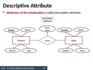
Descriptive Attribute
Attributes of the relationship is called descriptive attribute.
Student Book
Issue
RollNo Name
Branch Sem
BookNo Name
Author Price
Issue
Date
Descriptive
Attribute
20.
Unit – 3:Entity-Relationship Model 20
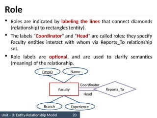
Role
Roles are indicated by labeling the lines that connect diamonds
(relationship) to rectangles (entity).
The labels “Coordinator” and “Head” are called roles; they specify
Faculty entities interact with whom via Reports_To relationship
set.
Role labels are optional, and are used to clarify semantics
(meaning) of the relationship.
Faculty Reports_To
EmpID Name
Branch Experience
Head
Coordinator
21.
Unit – 3:Entity-Relationship Model 21
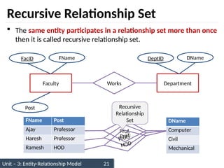
Recursive Relationship Set
The same entity participates in a relationship set more than once
then it is called recursive relationship set.
Faculty Department
Works
FacID FName
Post
DeptID DName
FName Post
Ajay Professor
Haresh Professor
Ramesh HOD
DName
Computer
Civil
Mechanical
Prof.
Prof.
Prof./
HOD
Recursive
Relationship
Set
22.
Unit – 3:Entity-Relationship Model 22
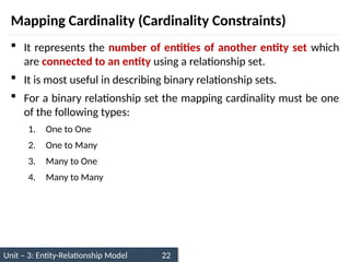
Mapping Cardinality (Cardinality Constraints)
It represents the number of entities of another entity set which
are connected to an entity using a relationship set.
It is most useful in describing binary relationship sets.
For a binary relationship set the mapping cardinality must be one
of the following types:
1. One to One
2. One to Many
3. Many to One
4. Many to Many
23.
Unit – 3:Entity-Relationship Model 23
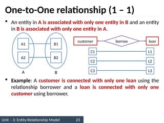
One-to-One relationship (1 – 1)
An entity in A is associated with only one entity in B and an entity
in B is associated with only one entity in A.
Example: A customer is connected with only one loan using the
relationship borrower and a loan is connected with only one
customer using borrower.
A1
A2
B1
B2
A B
customer loan
borrow
C1
C2
L1
L2
C3 L3
24.
Unit – 3:Entity-Relationship Model 24
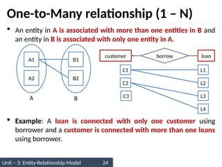
One-to-Many relationship (1 – N)
An entity in A is associated with more than one entities in B and
an entity in B is associated with only one entity in A.
Example: A loan is connected with only one customer using
borrower and a customer is connected with more than one loans
using borrower.
A1
A2
B1
B2
A B
customer loan
borrow
C1
C2
L1
L2
L4
L3
C3
25.
Unit – 3:Entity-Relationship Model 25
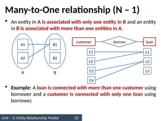
Many-to-One relationship (N – 1)
An entity in A is associated with only one entity in B and an entity
in B is associated with more than one entities in A.
Example: A loan is connected with more than one customer using
borrower and a customer is connected with only one loan using
borrower.
A1
A2
B1
B2
A B
customer loan
borrow
C1
C2
L1
L2
C4
L3
C3
26.
Unit – 3:Entity-Relationship Model 26
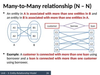
Many-to-Many relationship (N – N)
An entity in A is associated with more than one entities in B and
an entity in B is associated with more than one entities in A.
Example: A customer is connected with more than one loan using
borrower and a loan is connected with more than one customer
using borrower.
A1
A2
B1
B2
A B
customer loan
borrow
C1
C2
L1
L2
C4
L3
C3
L4
27.
Unit – 2:Relational Model 27
1. Give real life example of Mapping Cardinality.
Exercise
28.
Unit – 3:Entity-Relationship Model 28
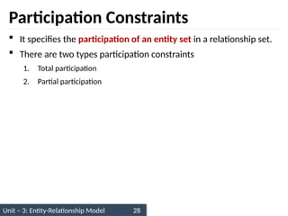
Participation Constraints
It specifies the participation of an entity set in a relationship set.
There are two types participation constraints
1. Total participation
2. Partial participation
29.
Unit – 3:Entity-Relationship Model 29
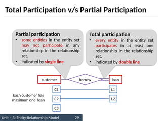
Total Participation v/s Partial Participation
customer loan
borrow
C1
C2
L1
L2
C3
Each customer has
maximum one loan
Total participation
• every entity in the entity set
participates in at least one
relationship in the relationship
set.
• indicated by double line
Partial participation
• some entities in the entity set
may not participate in any
relationship in the relationship
set.
• indicated by single line
30.
Unit – 3:Entity-Relationship Model 30
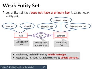
Weak Entity Set
An entity set that does not have a primary key is called weak
entity set.
loan payment
loan-no amount payment-no
Payment-date
L_P
Payment-amount
Strong Entity
Set
Weak Entity
Set
Weak Entity
Relationship
• Weak entity set is indicated by double rectangle.
• Weak entity relationship set is indicated by double diamond.
31.
Unit – 3:Entity-Relationship Model 31
Weak Entity Set
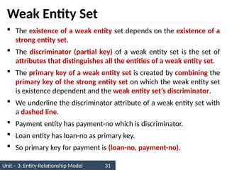
The existence of a weak entity set depends on the existence of a
strong entity set.
The discriminator (partial key) of a weak entity set is the set of
attributes that distinguishes all the entities of a weak entity set.
The primary key of a weak entity set is created by combining the
primary key of the strong entity set on which the weak entity set
is existence dependent and the weak entity set’s discriminator.
We underline the discriminator attribute of a weak entity set with
a dashed line.
Payment entity has payment-no which is discriminator.
Loan entity has loan-no as primary key.
So primary key for payment is (loan-no, payment-no).
32.
Unit – 3:Entity-Relationship Model 32
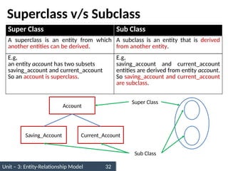
Superclass v/s Subclass
Account
Saving_Account Current_Account
Super Class
Sub Class
Super Class Sub Class
A superclass is an entity from which
another entities can be derived.
A subclass is an entity that is derived
from another entity.
E.g,
an entity account has two subsets
saving_account and current_account
So an account is superclass.
E.g,
saving_account and current_account
entities are derived from entity account.
So saving_account and current_account
are subclass.
33.
Unit – 3:Entity-Relationship Model 33
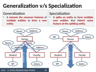
Generalization v/s Specialization
Student Faculty Student Faculty
Name
Address
SPI
Name
Address
Salary
Person
Name Address
ISA
Person
Name Address
SPI Salary
SPI Salary
ISA
Bottom-up
approach
Top-down
approach
Generalization
• It extracts the common features of
multiple entities to form a new
entity.
Specialization
• It splits an entity to form multiple
new entities that inherit some
feature of the splitting entity.
34.
Unit – 3:Entity-Relationship Model 34
Generalization v/s Specialization
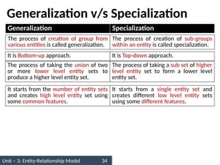
Generalization Specialization
The process of creation of group from
various entities is called generalization.
The process of creation of sub-groups
within an entity is called specialization.
It is Bottom-up approach. It is Top-down approach.
The process of taking the union of two
or more lower level entity sets to
produce a higher level entity set.
The process of taking a sub set of higher
level entity set to form a lower level
entity set.
It starts from the number of entity sets
and creates high level entity set using
some common features.
It starts from a single entity set and
creates different low level entity sets
using some different features.
35.
Unit – 3:Entity-Relationship Model 35
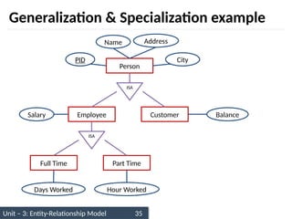
Generalization & Specialization example
Employee Customer
Person
Name Address
PID City
Salary Balance
ISA
Full Time Part Time
Days Worked Hour Worked
ISA
36.
Unit – 2:Relational Model 36
1. Give any two examples of Generalization/Specialization.
Exercise
37.
Unit – 3:Entity-Relationship Model 37
Constraints on Specialization and Generalization
Constraints
Disjoint Participation
Disjoint
Non-disjoint
(Overlapping)
Total
(Mandatory)
Partial
(Optional)
38.
Unit – 3:Entity-Relationship Model 38
Disjoint Constraint
It describes relationship between members of the superclass and
subclass and indicates whether member of a superclass can be a
member of one, or more than one subclass.
Types of disjoint constraints
1. Disjoint Constraint
2. Non-disjoint (Overlapping) Constraint
39.
Unit – 3:Entity-Relationship Model 39
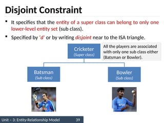
Disjoint Constraint
It specifies that the entity of a super class can belong to only one
lower-level entity set (sub class).
Specified by ‘d’ or by writing disjoint near to the ISA triangle.
Cricketer
(Super class)
Batsman
(Sub class)
Bowler
(Sub class)
All the players are associated
with only one sub class either
(Batsman or Bowler).
40.
Unit – 3:Entity-Relationship Model 40
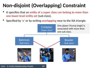
Non-disjoint (Overlapping) Constraint
It specifies that an entity of a super class can belong to more than
one lower-level entity set (sub class).
Specified by ‘o’ or by writing overlapping near to the ISA triangle.
Cricketer
(Super class)
Batsman
(Sub class)
Bowler
(Sub class)
One player (Yuvraj singh) is
associated with more than
one sub class.
41.
Unit – 3:Entity-Relationship Model 41
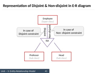
Representation of Disjoint & Non-disjoint in E-R diagram
Employee
(Super class)
Professor
(Sub class)
Head
(Sub class)
ISA
Non-disjoint
Disjoint
In case of
Disjoint constraint
In case of
Non- disjoint constraint
42.
Unit – 3:Entity-Relationship Model 42
Constraints on Specialization and Generalization
Constraints
Disjoint
Constraint
Participation
Constraint
Disjoint
Constraint
Non-disjoint
(Overlapping)
Total
(Mandatory)
Partial
(Optional)
43.
Unit – 3:Entity-Relationship Model 43
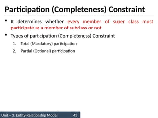
Participation (Completeness) Constraint
It determines whether every member of super class must
participate as a member of subclass or not.
Types of participation (Completeness) Constraint
1. Total (Mandatory) participation
2. Partial (Optional) participation
44.
Unit – 3:Entity-Relationship Model 44
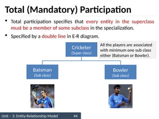
Total (Mandatory) Participation
Total participation specifies that every entity in the superclass
must be a member of some subclass in the specialization.
Specified by a double line in E-R diagram.
Cricketer
(Super class)
Batsman
(Sub class)
Bowler
(Sub class)
All the players are associated
with minimum one sub class
either (Batsman or Bowler).
45.
Unit – 3:Entity-Relationship Model 45
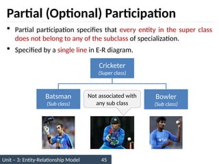
Partial (Optional) Participation
Partial participation specifies that every entity in the super class
does not belong to any of the subclass of specialization.
Specified by a single line in E-R diagram.
Not associated with
any sub class
Cricketer
(Super class)
Batsman
(Sub class)
Bowler
(Sub class)
46.
Unit – 3:Entity-Relationship Model 46
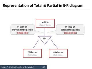
Representation of Total & Partial in E-R diagram
Vehicle
(Super class)
2 Wheeler
(Sub class)
4 Wheeler
(Sub class)
ISA
In case of
Partial participation
(Single line)
In case of
Total participation
(Double line)
47.
Unit – 3:Entity-Relationship Model 47
Limitation of E-R diagram
In E-R model we cannot express relationships between two
relationships.
Relation
Relation 1 Relation 2
Relation
Entity 1 Entity 2
48.
Unit – 3:Entity-Relationship Model 48
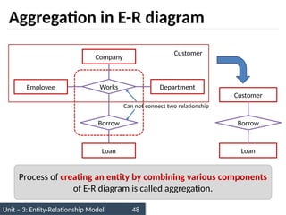
Aggregation in E-R diagram
Employee Department
Works
Borrow
Loan
Can not connect two relationship
Borrow
Loan
Customer
Customer
Company
Process of creating an entity by combining various components
of E-R diagram is called aggregation.
49.
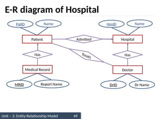
Unit – 3:Entity-Relationship Model 49
E-R diagram of Hospital
Patient Hospital
Admitted
PatID Name HosID Name
Has
Medical Record
MRID
Has
Doctor
DrID
Treats
Dr Name
Report Name
50.
Unit – 3:Entity-Relationship Model 50
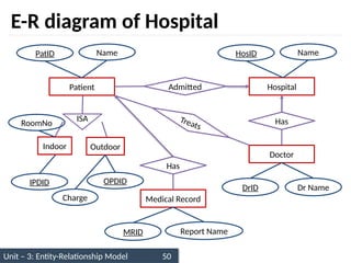
E-R diagram of Hospital
Patient Hospital
Admitted
PatID Name HosID Name
Has
Medical Record
MRID
Has
Doctor
DrID
Treats
Dr Name
Report Name
ISA
Indoor Outdoor
IPDID OPDID
RoomNo
Charge
51.
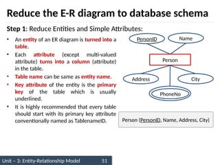
Unit – 3:Entity-Relationship Model 51
• An entity of an ER diagram is turned into a
table.
• Each attribute (except multi-valued
attribute) turns into a column (attribute)
in the table.
• Table name can be same as entity name.
• Key attribute of the entity is the primary
key of the table which is usually
underlined.
• It is highly recommended that every table
should start with its primary key attribute
conventionally named as TablenameID.
Reduce the E-R diagram to database schema
Person
PersonID Name
Address City
PhoneNo
Person (PersonID, Name, Address, City)
Step 1: Reduce Entities and Simple Attributes:
52.
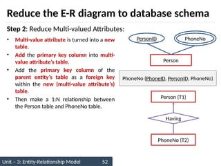
Unit – 3:Entity-Relationship Model 52
• Multi-value attribute is turned into a new
table.
• Add the primary key column into multi-
value attribute’s table.
• Add the primary key column of the
parent entity’s table as a foreign key
within the new (multi-value attribute’s)
table.
• Then make a 1:N relationship between
the Person table and PhoneNo table.
Reduce the E-R diagram to database schema
Step 2: Reduce Multi-valued Attributes:
Person
PersonID PhoneNo
Having
PhoneNo (T2)
Person (T1)
PhoneNo (PhoneID, PersonID, PhoneNo)
53.
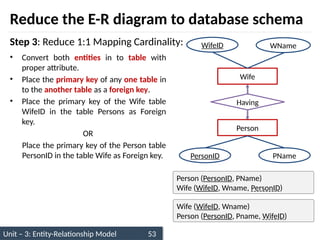
Unit – 3:Entity-Relationship Model 53
• Convert both entities in to table with
proper attribute.
• Place the primary key of any one table in
to the another table as a foreign key.
• Place the primary key of the Wife table
WifeID in the table Persons as Foreign
key.
OR
Place the primary key of the Person table
PersonID in the table Wife as Foreign key.
Reduce the E-R diagram to database schema
Step 3: Reduce 1:1 Mapping Cardinality:
Wife
WifeID WName
Person
PersonID PName
Having
Person (PersonID, PName)
Wife (WifeID, Wname, PersonID)
Wife (WifeID, Wname)
Person (PersonID, Pname, WifeID)
54.
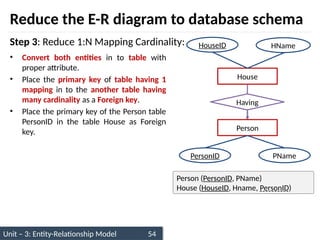
Unit – 3:Entity-Relationship Model 54
• Convert both entities in to table with
proper attribute.
• Place the primary key of table having 1
mapping in to the another table having
many cardinality as a Foreign key.
• Place the primary key of the Person table
PersonID in the table House as Foreign
key.
Reduce the E-R diagram to database schema
Step 3: Reduce 1:N Mapping Cardinality:
House
HouseID HName
Person
PersonID PName
Having
Person (PersonID, PName)
House (HouseID, Hname, PersonID)
55.
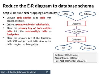
Unit – 3:Entity-Relationship Model 55
• Convert both entities in to table with
proper attribute.
• Create a separate table for relationship.
• Place the primary key of both entities
table into the relationship’s table as
foreign key.
• Place the primary key of the Customer
table CID and Account table Ano in the
table Has_Acct as Foreign key.
Reduce the E-R diagram to database schema
Step 3: Reduce N:N Mapping Cardinality:
Account
ANo Balance
Customer
CID CName
Has_Acct
Customer (CID, CName)
Account (ANo, Balance)
Has_Acct (HasAcctID, CID, ANo)
56.
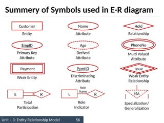
Unit – 3:Entity-Relationship Model 56
Summery of Symbols used in E-R diagram
Customer
Entity
EmpID
Primary Key
Attribute
Payment
Weak Entity
Total
Participation
Name
Attribute
Age
Derived
Attribute
PymtID
Discriminating
Attribute
Hold
Relationship
PhoneNo
Multi Valued
Attribute
Issue
Weak Entity
Relationship
ISA
Specialization/
Generalization
R
E
Role
Indicator
R
E
Role
Name
57.
Unit – 3:Entity-Relationship Model 57
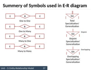
Summery of Symbols used in E-R diagram
One to One
R
E E
One to Many
R
E E
Many to One
R
E E
Many to Many
R
E E
ISA
Total
Specialization/
Generalization
ISA
Disjoint
Specialization/
Generalization
Disjoint
ISA
Overlapping
Specialization/
Generalization
Overlapping
58.
Unit – 3:Entity-Relationship Model 58
Questions
1. Write a note on mapping cardinality in E-R diagram.
2. Explain the difference between a weak and a strong entity set.
3. Explain the difference between generalization and specialization.
4. Write a note on constraints on specialization and generalization.
5. Explain aggregation in E-R diagram with example.
6. Draw E-R diagram for bank management system.
7. Construct an E-R diagram for a car-insurance company whose
customers own one or more cars each. Each car has associated
with it zero to any number of recorded accidents.