2.1
Week 2: Entity-RelationshipModel
Week 2: Entity-Relationship Model
Entity, Relationship, and E-R Diagram
Entity
Attributes
Weak/Regular Entity
Relationship
Degree
Mapping Cardinality
Relationship with Attributes
Participation
Keys
Extended E-R Features
Entity Specialization/Generalization
Relationship Aggregation
Design of an E-R Database Schema
2.
2.2
Entity, Relationship, andE-R Diagram
Entity, Relationship, and E-R Diagram
A database can be modeled as:
a collection of entities,
relationship among entities.
A database can be illustrated by an E-R diagram
3.
2.3
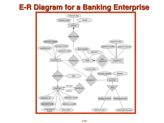
E-R Diagrams
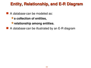
E-R Diagrams
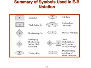
Rectangles represent entity sets.
Diamonds represent relationship sets.
Lines link attributes to entity sets and entity sets to relationship sets.
Ellipses represent attributes
Double ellipses represent multivalued attributes. (will study later)
Dashed ellipses denote derived attributes. (will study later)
Underline indicates primary key attributes (will study later)
4.
2.4
Entity Sets
Entity Sets
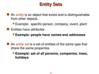
An entity is an object that exists and is distinguishable
from other objects.
Example: specific person, company, event, plant
Entities have attributes
Example: people have names and addresses
An entity set is a set of entities of the same type that
share the same properties.
Example: set of all persons, companies, trees,
holidays
5.
2.5
Entity Sets
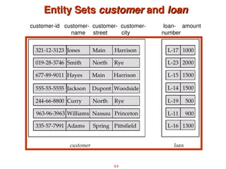
Entity Setscustomer
customer and
and loan
loan
customer-id customer- customer- customer- loan- amount
name street city number
6.
2.6
Attributes
Attributes
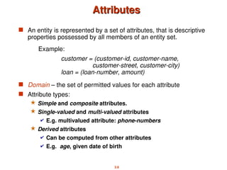
An entityis represented by a set of attributes, that is descriptive
properties possessed by all members of an entity set.
Domain – the set of permitted values for each attribute
Attribute types:
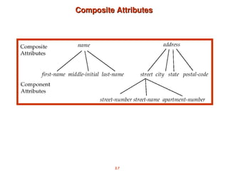
Simple and composite attributes.
Single-valued and multi-valued attributes
E.g. multivalued attribute: phone-numbers
Derived attributes
Can be computed from other attributes
E.g. age, given date of birth
Example:
customer = (customer-id, customer-name,
customer-street, customer-city)
loan = (loan-number, amount)
2.8
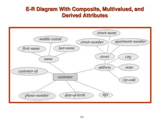
E-R Diagram WithComposite, Multivalued, and
E-R Diagram With Composite, Multivalued, and
Derived Attributes
Derived Attributes
9.
2.9
Weak Entity andRegular/Strong Entity
Weak Entity and Regular/Strong Entity
A weak entity is an entity that is existence-dependent
on some other entity. By contrast, a regular entity (or
“a strong entity”) is an entity which is not weak.
The existence of a weak entity set depends on the
existence of a identifying entity set
it must relate to the identifying entity set via a total,
one-to-many relationship set from the identifying to
the weak entity set
E.g. An employee’s dependents might be weak
entities --- they can’t exist (so far as the database is
concerned) if the relevant employee does not exist.
A weak entity type can be related to more than one
regular entity type.
10.
2.10
Weak Entity andRegular/Strong Entity
Weak Entity and Regular/Strong Entity
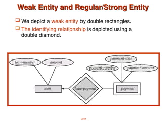
We depict a weak entity by double rectangles.
The identifying relationship is depicted using a
double diamond.
11.
2.11
Relationship Sets
Relationship Sets
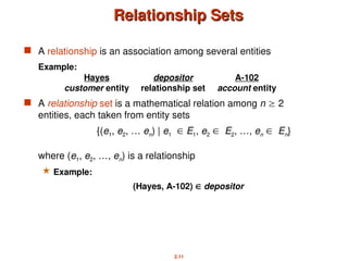
A relationship is an association among several entities
Example:
Hayes depositor A-102
customer entity relationship set account entity
A relationship set is a mathematical relation among n 2
entities, each taken from entity sets
{(e1, e2, … en) | e1 E1, e2 E2, …, en En}
where (e1, e2, …, en) is a relationship
Example:
(Hayes, A-102) depositor
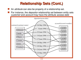
2.13
Relationship Sets (Cont.)
RelationshipSets (Cont.)
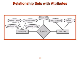
An attribute can also be property of a relationship set.
For instance, the depositor relationship set between entity sets
customer and account may have the attribute access-date
14.
2.14
Degree of aRelationship Set
Degree of a Relationship Set
Refers to number of entity sets that participate in a relationship
set.
Relationship sets that involve two entity sets are binary (or degree
two). Generally, most relationship sets in a database system are
binary.
Relationship sets may involve more than two entity sets.
Relationships between more than two entity sets are rare. Most
relationships are binary. (More on this later.)
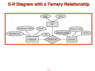
E.g. Suppose employees of a bank may have jobs
(responsibilities) at multiple branches, with different
jobs at different branches. Then there is a ternary
relationship set between entity sets employee, job
and branch
2.16
Binary Vs. Non-BinaryRelationships
Binary Vs. Non-Binary Relationships
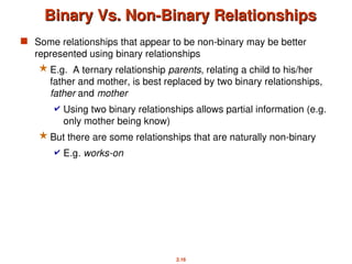
Some relationships that appear to be non-binary may be better
represented using binary relationships
E.g. A ternary relationship parents, relating a child to his/her
father and mother, is best replaced by two binary relationships,
father and mother
Using two binary relationships allows partial information (e.g.
only mother being know)
But there are some relationships that are naturally non-binary
E.g. works-on
17.
2.17
Roles
Roles
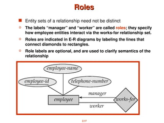
Entity setsof a relationship need not be distinct
o The labels “manager” and “worker” are called roles; they specify
how employee entities interact via the works-for relationship set.
o Roles are indicated in E-R diagrams by labeling the lines that
connect diamonds to rectangles.
o Role labels are optional, and are used to clarify semantics of the
relationship
18.
2.18
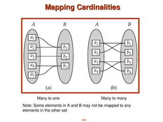
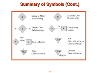
Mapping Cardinalities
Mapping Cardinalities
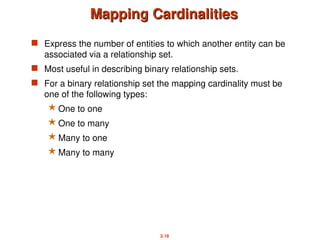
Express the number of entities to which another entity can be
associated via a relationship set.
Most useful in describing binary relationship sets.
For a binary relationship set the mapping cardinality must be
one of the following types:
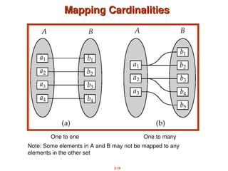
One to one
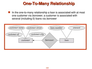
One to many
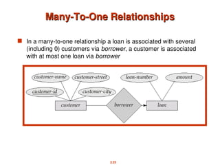
Many to one
Many to many
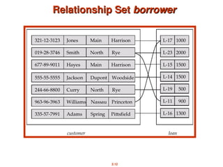
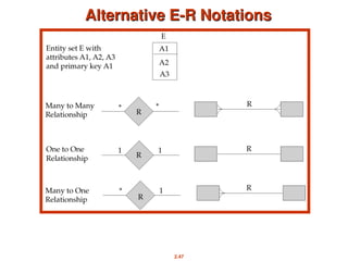
2.21
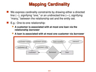
Mapping Cardinality
Mapping Cardinality
We express cardinality constraints by drawing either a directed
line (), signifying “one,” or an undirected line (—), signifying
“many,” between the relationship set and the entity set.
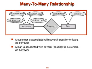
E.g.: One-to-one relationship:
A customer is associated with at most one loan via the
relationship borrower
A loan is associated with at most one customer via borrower
2.25
Mapping Cardinalities affectER Design
Mapping Cardinalities affect ER Design
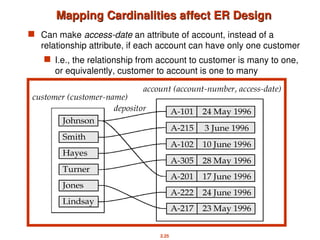
Can make access-date an attribute of account, instead of a
relationship attribute, if each account can have only one customer
I.e., the relationship from account to customer is many to one,
or equivalently, customer to account is one to many
2.27
Participation of anEntity Set in a
Participation of an Entity Set in a
Relationship Set
Relationship Set
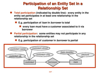
Total participation (indicated by double line): every entity in the
entity set participates in at least one relationship in the
relationship set
E.g. participation of loan in borrower is total
every loan must have a customer associated to it via
borrower
Partial participation: some entities may not participate in any
relationship in the relationship set
E.g. participation of customer in borrower is partial
28.
2.28
Keys
Keys
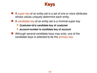
A superkey of an entity set is a set of one or more attributes
whose values uniquely determine each entity.
A candidate key of an entity set is a minimal super key
Customer-id is candidate key of customer
account-number is candidate key of account
Although several candidate keys may exist, one of the
candidate keys is selected to be the primary key.
29.
2.29
Keys for RelationshipSets
Keys for Relationship Sets
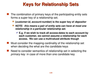
The combination of primary keys of the participating entity sets
forms a super key of a relationship set.
(customer-id, account-number) is the super key of depositor
NOTE: this means a pair of entity sets can have at most one
relationship in a particular relationship set.
E.g. if we wish to track all access-dates to each account by
each customer, we cannot assume a relationship for each
access. We can use a multivalued attribute though
Must consider the mapping cardinality of the relationship set
when deciding the what are the candidate keys
Need to consider semantics of relationship set in selecting the
primary key in case of more than one candidate key
30.
2.30
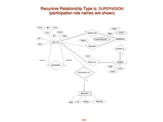
Recursive Relationship Typeis:
Recursive Relationship Type is: SUPERVISION
SUPERVISION
(participation role names are shown)
(participation role names are shown)
31.
2.31
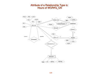
Attribute of aRelationship Type is:
Attribute of a Relationship Type is:
Hours of WORKS_ON
Hours of WORKS_ON
32.
2.32
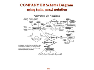
COMPANY ER SchemaDiagram
COMPANY ER Schema Diagram
using (min, max) notation
using (min, max) notation
2.34
Specialization
Specialization
Top-down designprocess; we designate subgroupings within an
entity set that are distinctive from other entities in the set.
These subgroupings become lower-level entity sets that have
attributes or participate in relationships that do not apply to the
higher-level entity set.
Depicted by a triangle component labeled ISA (E.g. customer “is
a” person).
Attribute inheritance – a lower-level entity set inherits all the
attributes and relationship participation of the higher-level entity
set to which it is linked.
2.36
Generalization
Generalization
A bottom-updesign process – combine a number of entity sets
that share the same features into a higher-level entity set.
Specialization and generalization are simple inversions of each
other; they are represented in an E-R diagram in the same way.
The terms specialization and generalization are used
interchangeably.
37.
2.37
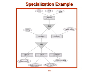
Specialization and Generalization
Specializationand Generalization
(Contd.)
(Contd.)
Can have multiple specializations of an entity set based on
different features.
E.g. permanent-employee vs. temporary-employee, in addition to
officer vs. secretary vs. teller
Each particular employee would be
a member of one of permanent-employee or temporary-
employee,
and also a member of one of officer, secretary, or teller
The ISA relationship also referred to as superclass - subclass
relationship
38.
2.38
Design Constraints ona
Design Constraints on a
Specialization/Generalization
Specialization/Generalization
Constraint on which entities can be members of a given
lower-level entity set.
condition-defined
E.g. all customers over 65 years are members of senior-
citizen entity set; senior-citizen ISA person.
user-defined
Constraint on whether or not entities may belong to more than
one lower-level entity set within a single generalization.
Disjoint
an entity can belong to only one lower-level entity set
Noted in E-R diagram by writing disjoint next to the ISA
triangle
Overlapping
an entity can belong to more than one lower-level entity
set
39.
2.39
Design Constraints ona
Design Constraints on a
Specialization/Generalization (Contd.)
Specialization/Generalization (Contd.)
Completeness constraint -- specifies whether or not an entity in
the higher-level entity set must belong to at least one of the
lower-level entity sets within a generalization.
total : an entity must belong to one of the lower-level entity sets
partial: an entity need not belong to one of the lower-level
entity sets
40.
2.40
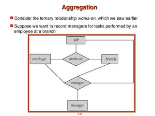
Aggregation
Aggregation
Consider theternary relationship works-on, which we saw earlier
Suppose we want to record managers for tasks performed by an
employee at a branch
41.
2.41
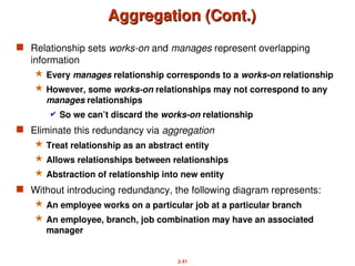
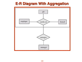
Aggregation (Cont.)
Aggregation (Cont.)
Relationship sets works-on and manages represent overlapping
information
Every manages relationship corresponds to a works-on relationship
However, some works-on relationships may not correspond to any
manages relationships
So we can’t discard the works-on relationship
Eliminate this redundancy via aggregation
Treat relationship as an abstract entity
Allows relationships between relationships
Abstraction of relationship into new entity
Without introducing redundancy, the following diagram represents:
An employee works on a particular job at a particular branch
An employee, branch, job combination may have an associated
manager
2.43
E-R Design Decisions
E-RDesign Decisions
The use of an attribute or entity set to represent an object.
Whether a real-world concept is best expressed by an entity set
or a relationship set.
The use of a ternary relationship versus a pair of binary
relationships.
The use of specialization/generalization – contributes to
modularity in the design.
The use of aggregation – can treat the aggregate entity set as a
single unit without concern for the details of its internal structure.


![谷歌留痕技术教程[ 𝙩𝙤𝙥 𝟮𝟯𝟯. 𝙘 𝙤𝙢 ]](https://cdn.slidesharecdn.com/ss_thumbnails/top233-260130173900-2eb784f9-thumbnail.jpg?width=640&height=640&fit=bounds)
