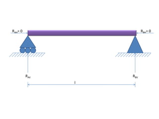
SlideShare a Scribd company logo
1 of 20
RAH= 0 RBH= 0
RAV RBV
l
RAH= 0 RBH= 0
RAV RBV
Load Intensity= W Kg/m
l/2 l/2
RAH= 0 RBH= 0
Load Intensity= W Kg/m
RAH= 0 RBH= 0
RAV RBV
Load Intensity= W Kg/m
RAH= 0 RBH= 0
Load Intensity= W Kg/m
RAH= 0 RBH= 0
Load Intensity= 3W Kg/m
Concentrated Load of 9W Kg Concentrated Load of 9W Kg
Y
X
x
The equation of the deflection of the beam at any distance
x from the ordinate axis is give by: -
From the equation it has been observed that the maximum
deflection occur at the middle part of the the beam and is
equal to: -
Y
X
x
= Deflection at middle of span
= Deflection at any linear distance ‘x’ from left of
span
= Deflection denoted by ‘y’.
RAV RBV
6D 6D
4D
6D
1D1D
2D 2D 2D
1D 1D
6D
The total moment of inertia about the axis XX(NEUTRAL AXIS) of fig. 1 =
The total moment of inertia about the axis XX(NEUTRAL AXIS) of fig. 2 =
Therfore the % by which the moment of areas of fig.2 is more than fig.1=
From the bending moment diagram as shown we can get the maximum bendimng moment is =
Fro that, for designing of the crossection the bending moment will be taken as=
The by he formula: -
M = ρ
I y (where I= moment of areas of the figure about neutral
axis
ρ= Bending stress
y= distance from the taken axis to the neutral axis)
The equation of the shear stress curve of this figure from axis (a<=y<b)=
Due to the symmetric about the xx the remaining shape of the curve will be same
as that above the abscissa
a
b
o
bl
al
(-)
(+)
The simplest equation of bending stress curve of this figure =
(-)
(+)
Moment generated by the force along X axis
Moment generated by the force along Y axis
Therefore, the combined stress acting act any point on the cross-section at the co-
ordinates (xl , yl ) is given by: -
Moment generated by the force along X axis
Moment generated by the force along Y axis
Therefore, the combined stress acting act any point on the cross-section at the co-
ordinates (xl , yl ) is given by: -
Presentation

More Related Content

What's hot

Step by step Engineering Mechanics updated
Step by step Engineering Mechanics updatedStep by step Engineering Mechanics updated
Step by step Engineering Mechanics updatedProf. S.Rajendiran
 
4 transvere shear-asgn
4 transvere shear-asgn4 transvere shear-asgn
4 transvere shear-asgnKingJyeWong
 
3 bending stress-asgn
3 bending stress-asgn3 bending stress-asgn
3 bending stress-asgnKingJyeWong
 
Shear force and bending moment diagram for simply supported beam _1P
Shear force and bending moment diagram for simply supported beam _1PShear force and bending moment diagram for simply supported beam _1P
Shear force and bending moment diagram for simply supported beam _1Psushma chinta
 
III - resultant of non-concurrent forces
III -  resultant of non-concurrent forcesIII -  resultant of non-concurrent forces
III - resultant of non-concurrent forcesdjpprkut
 
Analysis of three hinge parabolic arches
Analysis of three hinge parabolic archesAnalysis of three hinge parabolic arches
Analysis of three hinge parabolic archesnawalesantosh35
 
Problems on simply supported beams
Problems on simply supported beamsProblems on simply supported beams
Problems on simply supported beamssushma chinta
 
Engmech 06 (equilibrium of non_concurrent force system)
Engmech 06 (equilibrium of non_concurrent force system)Engmech 06 (equilibrium of non_concurrent force system)
Engmech 06 (equilibrium of non_concurrent force system)physics101
 
Angular motion problem set c torque solutions
Angular motion problem set c   torque solutionsAngular motion problem set c   torque solutions
Angular motion problem set c torque solutionsDarrin Ellsworth
 
Engineering science N4 (FET College)
Engineering science N4 (FET College)Engineering science N4 (FET College)
Engineering science N4 (FET College)Jude Jay
 
flammants problem by line load and point load
flammants problem by line load and point loadflammants problem by line load and point load
flammants problem by line load and point loadMadhuReddy163523
 
Shear Force and Bending moment Diagram
Shear Force and Bending moment DiagramShear Force and Bending moment Diagram
Shear Force and Bending moment DiagramAshish Mishra
 
Sfd and bmd engineering science n4
Sfd and bmd engineering science n4Sfd and bmd engineering science n4
Sfd and bmd engineering science n4Jude Jay
 

What's hot (19)

Step by step Engineering Mechanics updated
Step by step Engineering Mechanics updatedStep by step Engineering Mechanics updated
Step by step Engineering Mechanics updated
 
311 C H12
311 C H12311 C H12
311 C H12
 
4 transvere shear-asgn
4 transvere shear-asgn4 transvere shear-asgn
4 transvere shear-asgn
 
3 bending stress-asgn
3 bending stress-asgn3 bending stress-asgn
3 bending stress-asgn
 
Shear force and bending moment diagram for simply supported beam _1P
Shear force and bending moment diagram for simply supported beam _1PShear force and bending moment diagram for simply supported beam _1P
Shear force and bending moment diagram for simply supported beam _1P
 
III - resultant of non-concurrent forces
III -  resultant of non-concurrent forcesIII -  resultant of non-concurrent forces
III - resultant of non-concurrent forces
 
Analysis of three hinge parabolic arches
Analysis of three hinge parabolic archesAnalysis of three hinge parabolic arches
Analysis of three hinge parabolic arches
 
Problems on simply supported beams
Problems on simply supported beamsProblems on simply supported beams
Problems on simply supported beams
 
Engmech 06 (equilibrium of non_concurrent force system)
Engmech 06 (equilibrium of non_concurrent force system)Engmech 06 (equilibrium of non_concurrent force system)
Engmech 06 (equilibrium of non_concurrent force system)
 
Angular motion problem set c torque solutions
Angular motion problem set c   torque solutionsAngular motion problem set c   torque solutions
Angular motion problem set c torque solutions
 
Assignment no 1
Assignment no 1Assignment no 1
Assignment no 1
 
Perfiles HEB
Perfiles HEBPerfiles HEB
Perfiles HEB
 
Mechanical Engineering Assignment Help
Mechanical Engineering Assignment HelpMechanical Engineering Assignment Help
Mechanical Engineering Assignment Help
 
Stresses in Beams
Stresses in BeamsStresses in Beams
Stresses in Beams
 
Engineering science N4 (FET College)
Engineering science N4 (FET College)Engineering science N4 (FET College)
Engineering science N4 (FET College)
 
flammants problem by line load and point load
flammants problem by line load and point loadflammants problem by line load and point load
flammants problem by line load and point load
 
Curved Beams
Curved Beams Curved Beams
Curved Beams
 
Shear Force and Bending moment Diagram
Shear Force and Bending moment DiagramShear Force and Bending moment Diagram
Shear Force and Bending moment Diagram
 
Sfd and bmd engineering science n4
Sfd and bmd engineering science n4Sfd and bmd engineering science n4
Sfd and bmd engineering science n4
 

Similar to Presentation

Relation between load shear force and bending moment of beams
Relation between load shear force and bending moment of  beamsRelation between load shear force and bending moment of  beams
Relation between load shear force and bending moment of beamssushma chinta
 
6002 notes 07_l7
6002 notes 07_l76002 notes 07_l7
6002 notes 07_l7ayobaness
 
Lecture--15, 16 (Deflection of beams).pptx
Lecture--15, 16 (Deflection of beams).pptxLecture--15, 16 (Deflection of beams).pptx
Lecture--15, 16 (Deflection of beams).pptxkhizeraftab1018
 
Chapter one.pptx
Chapter one.pptxChapter one.pptx
Chapter one.pptxhaymanot16
 
Unsymmetrical bending.ppt
Unsymmetrical bending.pptUnsymmetrical bending.ppt
Unsymmetrical bending.pptVenkatesh Ca
 
Forces acting on the beam with shear force & bending moment
Forces acting on the beam with shear force & bending momentForces acting on the beam with shear force & bending moment
Forces acting on the beam with shear force & bending momentTaral Soliya
 
WavesAppendix.pdf
WavesAppendix.pdfWavesAppendix.pdf
WavesAppendix.pdfcfisicaster
 
pdfslide.net_unsymmetrical-bendingppt.pdf
pdfslide.net_unsymmetrical-bendingppt.pdfpdfslide.net_unsymmetrical-bendingppt.pdf
pdfslide.net_unsymmetrical-bendingppt.pdfAkhileshKumar374947
 
Shear And Moment Diagrams
Shear And Moment DiagramsShear And Moment Diagrams
Shear And Moment DiagramsAmr Hamed
 
Chapter nine.pptx
Chapter nine.pptxChapter nine.pptx
Chapter nine.pptxhaymanot16
 
Direct-Bendng-Stress-pptx IMP.pptx
Direct-Bendng-Stress-pptx IMP.pptxDirect-Bendng-Stress-pptx IMP.pptx
Direct-Bendng-Stress-pptx IMP.pptxSougata Das
 
Uniaxial stresses
Uniaxial stressesUniaxial stresses
Uniaxial stressesYatin Singh
 
Engineering Science(1)
Engineering Science(1)Engineering Science(1)
Engineering Science(1)Jude Jay
 
Damped and undamped motion differential equations.pptx
Damped and undamped motion differential equations.pptxDamped and undamped motion differential equations.pptx
Damped and undamped motion differential equations.pptxBrijeshMishra525980
 
2nd codition of equilibrium
2nd codition of equilibrium2nd codition of equilibrium
2nd codition of equilibriumNestor Enriquez
 

Similar to Presentation (20)

Relation between load shear force and bending moment of beams
Relation between load shear force and bending moment of  beamsRelation between load shear force and bending moment of  beams
Relation between load shear force and bending moment of beams
 
6002 notes 07_l7
6002 notes 07_l76002 notes 07_l7
6002 notes 07_l7
 
Lecture--15, 16 (Deflection of beams).pptx
Lecture--15, 16 (Deflection of beams).pptxLecture--15, 16 (Deflection of beams).pptx
Lecture--15, 16 (Deflection of beams).pptx
 
10.01.03.029
10.01.03.02910.01.03.029
10.01.03.029
 
Chapter one.pptx
Chapter one.pptxChapter one.pptx
Chapter one.pptx
 
Unsymmetrical bending.ppt
Unsymmetrical bending.pptUnsymmetrical bending.ppt
Unsymmetrical bending.ppt
 
Forces acting on the beam with shear force & bending moment
Forces acting on the beam with shear force & bending momentForces acting on the beam with shear force & bending moment
Forces acting on the beam with shear force & bending moment
 
WavesAppendix.pdf
WavesAppendix.pdfWavesAppendix.pdf
WavesAppendix.pdf
 
pdfslide.net_unsymmetrical-bendingppt.pdf
pdfslide.net_unsymmetrical-bendingppt.pdfpdfslide.net_unsymmetrical-bendingppt.pdf
pdfslide.net_unsymmetrical-bendingppt.pdf
 
Ce 255 handout
Ce 255 handoutCe 255 handout
Ce 255 handout
 
Module 5
Module 5Module 5
Module 5
 
Shear And Moment Diagrams
Shear And Moment DiagramsShear And Moment Diagrams
Shear And Moment Diagrams
 
Chapter nine.pptx
Chapter nine.pptxChapter nine.pptx
Chapter nine.pptx
 
Direct-Bendng-Stress-pptx IMP.pptx
Direct-Bendng-Stress-pptx IMP.pptxDirect-Bendng-Stress-pptx IMP.pptx
Direct-Bendng-Stress-pptx IMP.pptx
 
Uniaxial stresses
Uniaxial stressesUniaxial stresses
Uniaxial stresses
 
Eccetric columns
Eccetric columnsEccetric columns
Eccetric columns
 
Engineering Science(1)
Engineering Science(1)Engineering Science(1)
Engineering Science(1)
 
Damped and undamped motion differential equations.pptx
Damped and undamped motion differential equations.pptxDamped and undamped motion differential equations.pptx
Damped and undamped motion differential equations.pptx
 
2nd codition of equilibrium
2nd codition of equilibrium2nd codition of equilibrium
2nd codition of equilibrium
 
Bending stress
Bending stressBending stress
Bending stress
 

Presentation

  • 1. RAH= 0 RBH= 0 RAV RBV l
  • 2. RAH= 0 RBH= 0 RAV RBV Load Intensity= W Kg/m l/2 l/2
  • 3. RAH= 0 RBH= 0 Load Intensity= W Kg/m
  • 4. RAH= 0 RBH= 0 RAV RBV Load Intensity= W Kg/m
  • 5. RAH= 0 RBH= 0 Load Intensity= W Kg/m
  • 6. RAH= 0 RBH= 0 Load Intensity= 3W Kg/m Concentrated Load of 9W Kg Concentrated Load of 9W Kg
  • 7. Y X x The equation of the deflection of the beam at any distance x from the ordinate axis is give by: - From the equation it has been observed that the maximum deflection occur at the middle part of the the beam and is equal to: -
  • 8. Y X x = Deflection at middle of span = Deflection at any linear distance ‘x’ from left of span = Deflection denoted by ‘y’. RAV RBV
  • 9.
  • 10.
  • 11.
  • 12. 6D 6D 4D 6D 1D1D 2D 2D 2D 1D 1D 6D
  • 13. The total moment of inertia about the axis XX(NEUTRAL AXIS) of fig. 1 = The total moment of inertia about the axis XX(NEUTRAL AXIS) of fig. 2 = Therfore the % by which the moment of areas of fig.2 is more than fig.1= From the bending moment diagram as shown we can get the maximum bendimng moment is = Fro that, for designing of the crossection the bending moment will be taken as= The by he formula: - M = ρ I y (where I= moment of areas of the figure about neutral axis ρ= Bending stress y= distance from the taken axis to the neutral axis)
  • 14. The equation of the shear stress curve of this figure from axis (a<=y<b)= The equation of the shear stress curve of this figure from axis (a<=y<b)= Due to the symmetric about the xx the remaining shape of the curve will be same as that above the abscissa a b o bl al
  • 15. (-) (+) The simplest equation of bending stress curve of this figure =
  • 16. The simplest equation of bending stress curve of this figure =
  • 18. Moment generated by the force along X axis Moment generated by the force along Y axis Therefore, the combined stress acting act any point on the cross-section at the co- ordinates (xl , yl ) is given by: -
  • 19. Moment generated by the force along X axis Moment generated by the force along Y axis Therefore, the combined stress acting act any point on the cross-section at the co- ordinates (xl , yl ) is given by: -