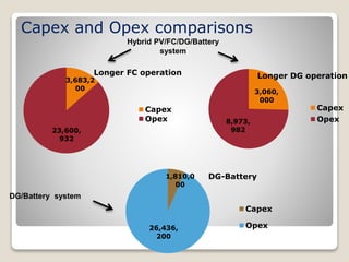
1
Hybrid Controller for
Renewable Energy Power Plant
in Stand-alone sites
Dr. Prabodh Bajpai
Assistant Professor
Electrical Engineering Department, IIT Kharagpur
1
Outline
 Introduction
 Technology aspects
 Benefit to the Industry
 Commercialization prospective
Hybrid Controller for Renewable Energy Power Plant in Stand-alone sites
2
Introduction
 Uncontrolled Renewable energy sources essentially
have random behaviors. eg: Solar, Wind, etc.
 Power production from Uncontrolled sources is
independent of human intervention
 Hybrid power systems may contain controlled and
uncontrolled energy sources and energy storage
elements with appropriate control systems
 Stand-alone hybrid power systems take advantage of
the complementary nature in profile of the renewable
energy sources
 Hybrid power systems ensure continuous and reliable
power production
Hybrid Controller for Renewable Energy Power Plant in Stand-alone sites
3
Possible Renewable Hybrid Energy
Systems
1) Wind/PV/FC/electrolyzer/
battery system
2) Micro-turbine/FC system
3) Microturbine/wind system
4) Gas-turbine/FC
system
5) Diesel/FC system
6) PV/battery
7) PV/FC/electrolyzer
8) PV/FC/electrolyzer/battery
system
9) FC/battery, or super-
capacitor system
10) Wind/FC system
11) Wind/diesel system
12) Wind/PV/battery
system
13) PV/diesel system
14) Diesel/wind/PV system
15) PV/FC/ SMES system
4
Wind and solar power generation are two of the most
promising renewable power generation technologies.
4
Hybrid Controller for Renewable Energy Power Plant in Stand-alone sites
DG/Battery Hybrid Solution: Merits
 Easy to install and low cost on site construction
 Highly integrated intelligent hybrid power system
for control and protection
 Inclusion of battery back up reduces the DG size
Saving in diesel and reduction in maintenance of diesel
generator
Reduced operating time and enhanced DG life
 Specially designed deep cycle battery available in
market
Rechargeable in a short time,
Long cycle life under STC,
High DoD (Depth of Discharge)
5
5
Hybrid Controller for Renewable Energy Power Plant in Stand-alone sites
DG based Hybrid Solution : Demerits
 DG as energy source has problems of :
 Pollution
 air, noise, heat
 Dependence of fuel
 world-wide increase of oil prices; limited resources in future
 Transport to the sites
 long distances and cost intensive transports
 Storage of the fuel at site
 safety problems - explosions, vandalism
 No unattended operation is possible
 high personnel cost
 High maintenance cost and limited life-time of DG
Hybrid Controller for Renewable Energy Power Plant in Stand-alone sites 6
Hybrid Renewable Energy Systems
 On the other hand, the proposed renewable energy
based system helps in:
 Decrease environmental pollution
Reduction of air emission
 Energy saving
Reduces production and purchase of fossil fuels
 Abatement of global warming
CO2 and other green house gases are not produced
 Socioeconomic development
Develops employment opportunities in rural areas
 Fuel supply diversity
Diversity of energy carriers and suppliers
 Distributed power generation
Reduces requirement for transmission lines within the electricity grid
Hybrid Controller for Renewable Energy Power Plant in Stand-alone sites 7
Challenges
 Site dependence of renewable sources
Site survey with long term data acquisition & forecasting
 Hybrid renewable energy system design
Configuration and sizing of the hybrid system
components with the objectives:
Supplying the power reliably under varying atmospheric
conditions
Minimizing the total cost of the system
Maximizing the system efficiency by efficient energy flow
management strategies
Optimization through simulation studies under real
operating conditions for a reasonable tradeoff among
conflicting design objectives
8
Hybrid Controller for Renewable Energy Power Plant in Stand-alone sites
Challenges
 Economic viability
Cost-benefit analysis of hybrid system for
reasonable payback period
 Real world application
 Design of power conditioning devices with
maximum power point operation of energy sources
 Optimal energy management strategies and their
testing with laboratory prototype hybrid controller
 Development of hardware and associated software
for field-implementation
Hybrid Controller for Renewable Energy Power Plant in Stand-alone sites
9
9
Technology aspects
Hybrid Controller for Renewable Energy Power Plant in Stand-alone sites
10
Introduction
 Solar PV based renewable power plant with FC,
Battery and DG as backup sources
 Hybrid controller to implement the energy
sources changeover logic based on optimal
energy management strategy.
 Automatic mode of operation in the hybrid
controller for FC and DG changeover operations.
 Laboratory prototype of hybrid Solar PV-Fuel
Cell-Battery-DG system for upto 5 kW load
Hybrid Controller for Renewable Energy Power Plant in Stand-alone sites
11
A typical stand-alone PV-Fuel cell-
Battery hybrid energy system:
12
Hybrid Controller for Renewable Energy Power Plant in Stand-alone sites
System Development
 Robustness of the controller to fluctuating weather
conditions and load demand is being rigorously
tested, monitored and documented.
 Hybrid controller comprises of:
◦ Solar DSCAM (master controller) and two slave controllers,
the Fuel Cell DSCAM and DG DSCAM
◦ Individual power conditioning units for SPV, Fuel Cell and
DG system to provide regulated DC output on the DC bus.
• The master and slave controllers interact to
provide switching and control signals for the
converter units.
Hybrid Controller for Renewable Energy Power Plant in Stand-alone sites
13
SPV-FC-BATTERY-DG HYBRID ENERGY POWER PLANT
Discharging
Charging
Supply to
Load
PV Power
FC Power
DG Power
SOLAR PV ARRAY (Primary Source)
BATTERY BANK ( Back Up Source)
FUEL CELL SYSTEM (Back Up Source)
CONTROLLER
DIESEL GENERATOR (Back
Up Source)
LOAD
H2 storage
H2
Supply
Experimental Test Results
0
10
20
30
40
50
60
Voltage
(V)
Time of the day (hr)
SPV Module-1
Voltage (V)
FC Module-1
Voltage (V)
DG Module-1
Voltage (V)
System Voltage
(V)
Battery-3 Voltage
(V)
Load Voltage (V)
FC
Operation
Battery
Operation
DG
Operation
Battery
Operation
SPV
Operation
SPV
Operation
Hybrid Controller for Renewable Energy Power Plant in Stand-alone sites
15
Load 0.75
kW
Load 1 kW
-40
-30
-20
-10
0
10
20
30
40
50
60
Current
(A)
Time of the day (hr)
SPV Input Current (A)
SPV Module-1 Current (A)
FC Input Current (A)
FC Module-1 Current (A)
FC Module-2 Current (A)
DG Module-1 Current (A)
DG Module-2 Current (A)
System Current (A)
Battery Current (A)
Load Current (A)
SPV Operation
Battery
Operation
FC
Operation
DG
Operation
SPV
Operation
Battery
Operation
Experimental Test Results
Hybrid Controller for Renewable Energy Power Plant in Stand-alone sites
16
Load 0.75 kW Load 1 kW
Excess Current
Battery Charging
Battery Charging
Merits of Topology
 Merits of solar PV charge controller and
Fuel Cell charge controller
◦ Optimal charging of the batteries and maximum power
extraction from solar PV and FC
◦ Supervisory functions to prevent damage to the battery
◦ Effective interface to inter connect Solar PV modules, Fuel
Cell, Battery Bank and the load
◦ Battery reaches a high state of charge under all operating
conditions
◦ Work in tandem with the SMPS based power plant to
optimize the charging capability of the FC/SPV and
protect the batteries from overcharge
Hybrid Controller for Renewable Energy Power Plant in Stand-alone sites
17
Important Features of Topology
◦ Use of solid-state devices to control the charging current to
the battery and supply power to the load simultaneously
◦ Blocking devices to prevent reverse current flow from the
battery to the FC/SPV during cloudy days or other charging
modes
◦ Lightning / transient protection to protect the control circuitry
from damage due to excessive voltage
◦ Programmable charging capacity, change over settings and
peak power point
◦ Programmable maximum power point tracking (MPPT) logic
with the built in embedded logic controller
Hybrid Controller for Renewable Energy Power Plant in Stand-alone sites
18
Solar resource assessment (SRA) system
Hybrid Controller for Renewable Energy Power Plant in Stand-alone sites
19
•Measures weather parameters like
• solar insolation (W/m2),
• ambient temperature (0C) and
• relative humidity(%)
•Weather data at defined intervals
is measured using sensors
•Data is sent continuously to a
central server through GPRS and is
monitored online
Necessity of weather
monitoring
•Inspecting the feasibility of a site for
a solar energy project
•Site comparison and selection based
on weather data
•Long term energy assessment helps
in effective system sizing and cost
minimization
•Helps to predict the performance of
SPV
Remote Monitoring System
Hybrid Controller for Renewable Energy Power Plant in Stand-alone sites 20
Sensors
Hybrid Controller
cRIO-9073, Data acquiring,
Generating and logging
Monitoring Station
Remote PC
Benefit to Industry
Hybrid Controller for Renewable
Energy Power Plant in Stand-
alone sites 21
Market potential
 Extendable to a generalized solution for any kind of
stand-alone site.
 Independent of continuous availability of the
renewable source as well as grid power availability.
 Power converters are modular in nature
 For any kind of critical load in stand-alone site
◦ Telecom towers,
◦ Cold storage plants,
◦ Hospitals,
◦ Military establishments
◦ Fuel stations
◦ ATMs
Hybrid Controller for Renewable Energy Power Plant in Stand-alone sites 22
Commercialization prospective
Hybrid Controller for Renewable
Energy Power Plant in Stand-
alone sites 23
Cost-benefit analysis
 Net present value = Total lifetime savings –
Total lifetime investment
 Savings include revenue generated from the
hybrid PV system by replacing the DG-battery
system, the carbon tax benefit and savings in
the operational cost of the system.
 Investment includes the extra first cost which is
the difference between the Capex of the hybrid
PV system and the Capex of the DG-Battery
system
Hybrid Controller for Renewable Energy Power Plant in Stand-alone sites 24
Cost-benefit analysis
 CAPEX for hybrid PV system to meet 4kW
peak load will around 50Lakh INR
 The lifetime of both the systems considered
to be 30 years.
 Economic analysis for different scenarios
gives payback period between 5-10 years
Hybrid Controller for Renewable Energy Power Plant in Stand-alone sites 25
Real world application
 Proof of concept verified with a laboratory
prototype
 Field site testing with stand-alone load
application needs to be done
 The Technology Transfer may take place as per
One Time License Payment or Revenue Sharing
Model or any other criteria mutually agreed
Hybrid Controller for Renewable Energy Power Plant in Stand-alone sites 26
Hybrid Controller for Renewable
Energy Power Plant in Stand-
alone sites 27
Component size and price
Component Pricing
PV (per Wp) 70
Battery (per kwh) 7,000
H2 tanks(per m3) 400
Fuel cell(per kW) 2,00,000
Diesel Generator (per
kW)
33,000
Diesel (per litre) 40
Component Size
PV (Wp) 16500
Battery in hybrid PV system(kwh) 57.6
DG in hybrid PV system (kW) 5
H2 tanks (m3) 120
Fuel cell (kW) 4.56
DG in DG-Battery system (kW) 25
Battery in DG-Battery system(
kWh)
105
Financial Assumptions
 Hybrid PV system:
• CAPEX is the total initial cost of the system.
 OPEX in case1 =1% of CAPEX+ 100% of Battery cost in every 5
years+100% of FC cost every 10,000 hours of operation+
operating cost of FC @Rs 417/hr +operating cost of DG @Rs
50/hr.
 OPEX in case2 =1% of CAPEX+ 100% of Battery cost in every 5
years+100% of DG cost in every 15 years + operating cost of FC
@Rs 417/hr+ operating cost of DG @Rs 50/hr.
 DG/Battery system:
• CAPEX is the total initial cost of the system.
 OPEX =2% of CAPEX+100% of Battery cost in every 5
years+100% of DG cost in every 8 years + operating cost of DG
@Rs 50/hr.
 The lifetime of both the systems was considered to be 30 years.
 The present diesel cost was assumed to be Rs 40/litre.
 The annual escalation in diesel cost was assumed to be @ 10 %
Capex and Opex comparisons
3,060,
000
8,973,
982
Longer DG operation
Capex
Opex
3,683,2
00
23,600,
932
Longer FC operation
Capex
Opex
1,810,0
00
26,436,
200
DG-Battery
Capex
Opex
Hybrid PV/FC/DG/Battery
system
DG/Battery system
Comparison of savings & investments for
hybrid PV/FC/DG/Battery system
25,217,
247
27,284,
132
Longer FC operation
Savings
Investmen
ts 37,400,
995
12,657,
182
Longer DG operation
Savings
Investmen
ts
NPV and Payback Period
Longer FC operation Longer DG
operation
With carbon
tax benefit 23,344,047 35,527,795
Net present
value
Without
carbon tax
benefit
16,463,765 29,068,754
With carbon
tax benefit
5 4
Payback period
Without
carbon tax
benefit
7 6

Ppt.ppt

  • 1.
    1 Hybrid Controller for RenewableEnergy Power Plant in Stand-alone sites Dr. Prabodh Bajpai Assistant Professor Electrical Engineering Department, IIT Kharagpur 1
  • 2.
    Outline  Introduction  Technologyaspects  Benefit to the Industry  Commercialization prospective Hybrid Controller for Renewable Energy Power Plant in Stand-alone sites 2
  • 3.
    Introduction  Uncontrolled Renewableenergy sources essentially have random behaviors. eg: Solar, Wind, etc.  Power production from Uncontrolled sources is independent of human intervention  Hybrid power systems may contain controlled and uncontrolled energy sources and energy storage elements with appropriate control systems  Stand-alone hybrid power systems take advantage of the complementary nature in profile of the renewable energy sources  Hybrid power systems ensure continuous and reliable power production Hybrid Controller for Renewable Energy Power Plant in Stand-alone sites 3
  • 4.
    Possible Renewable HybridEnergy Systems 1) Wind/PV/FC/electrolyzer/ battery system 2) Micro-turbine/FC system 3) Microturbine/wind system 4) Gas-turbine/FC system 5) Diesel/FC system 6) PV/battery 7) PV/FC/electrolyzer 8) PV/FC/electrolyzer/battery system 9) FC/battery, or super- capacitor system 10) Wind/FC system 11) Wind/diesel system 12) Wind/PV/battery system 13) PV/diesel system 14) Diesel/wind/PV system 15) PV/FC/ SMES system 4 Wind and solar power generation are two of the most promising renewable power generation technologies. 4 Hybrid Controller for Renewable Energy Power Plant in Stand-alone sites
  • 5.
    DG/Battery Hybrid Solution:Merits  Easy to install and low cost on site construction  Highly integrated intelligent hybrid power system for control and protection  Inclusion of battery back up reduces the DG size Saving in diesel and reduction in maintenance of diesel generator Reduced operating time and enhanced DG life  Specially designed deep cycle battery available in market Rechargeable in a short time, Long cycle life under STC, High DoD (Depth of Discharge) 5 5 Hybrid Controller for Renewable Energy Power Plant in Stand-alone sites
  • 6.
    DG based HybridSolution : Demerits  DG as energy source has problems of :  Pollution  air, noise, heat  Dependence of fuel  world-wide increase of oil prices; limited resources in future  Transport to the sites  long distances and cost intensive transports  Storage of the fuel at site  safety problems - explosions, vandalism  No unattended operation is possible  high personnel cost  High maintenance cost and limited life-time of DG Hybrid Controller for Renewable Energy Power Plant in Stand-alone sites 6
  • 7.
    Hybrid Renewable EnergySystems  On the other hand, the proposed renewable energy based system helps in:  Decrease environmental pollution Reduction of air emission  Energy saving Reduces production and purchase of fossil fuels  Abatement of global warming CO2 and other green house gases are not produced  Socioeconomic development Develops employment opportunities in rural areas  Fuel supply diversity Diversity of energy carriers and suppliers  Distributed power generation Reduces requirement for transmission lines within the electricity grid Hybrid Controller for Renewable Energy Power Plant in Stand-alone sites 7
  • 8.
    Challenges  Site dependenceof renewable sources Site survey with long term data acquisition & forecasting  Hybrid renewable energy system design Configuration and sizing of the hybrid system components with the objectives: Supplying the power reliably under varying atmospheric conditions Minimizing the total cost of the system Maximizing the system efficiency by efficient energy flow management strategies Optimization through simulation studies under real operating conditions for a reasonable tradeoff among conflicting design objectives 8 Hybrid Controller for Renewable Energy Power Plant in Stand-alone sites
  • 9.
    Challenges  Economic viability Cost-benefitanalysis of hybrid system for reasonable payback period  Real world application  Design of power conditioning devices with maximum power point operation of energy sources  Optimal energy management strategies and their testing with laboratory prototype hybrid controller  Development of hardware and associated software for field-implementation Hybrid Controller for Renewable Energy Power Plant in Stand-alone sites 9 9
  • 10.
    Technology aspects Hybrid Controllerfor Renewable Energy Power Plant in Stand-alone sites 10
  • 11.
    Introduction  Solar PVbased renewable power plant with FC, Battery and DG as backup sources  Hybrid controller to implement the energy sources changeover logic based on optimal energy management strategy.  Automatic mode of operation in the hybrid controller for FC and DG changeover operations.  Laboratory prototype of hybrid Solar PV-Fuel Cell-Battery-DG system for upto 5 kW load Hybrid Controller for Renewable Energy Power Plant in Stand-alone sites 11
  • 12.
    A typical stand-alonePV-Fuel cell- Battery hybrid energy system: 12 Hybrid Controller for Renewable Energy Power Plant in Stand-alone sites
  • 13.
    System Development  Robustnessof the controller to fluctuating weather conditions and load demand is being rigorously tested, monitored and documented.  Hybrid controller comprises of: ◦ Solar DSCAM (master controller) and two slave controllers, the Fuel Cell DSCAM and DG DSCAM ◦ Individual power conditioning units for SPV, Fuel Cell and DG system to provide regulated DC output on the DC bus. • The master and slave controllers interact to provide switching and control signals for the converter units. Hybrid Controller for Renewable Energy Power Plant in Stand-alone sites 13
  • 14.
    SPV-FC-BATTERY-DG HYBRID ENERGYPOWER PLANT Discharging Charging Supply to Load PV Power FC Power DG Power SOLAR PV ARRAY (Primary Source) BATTERY BANK ( Back Up Source) FUEL CELL SYSTEM (Back Up Source) CONTROLLER DIESEL GENERATOR (Back Up Source) LOAD H2 storage H2 Supply
  • 15.
    Experimental Test Results 0 10 20 30 40 50 60 Voltage (V) Timeof the day (hr) SPV Module-1 Voltage (V) FC Module-1 Voltage (V) DG Module-1 Voltage (V) System Voltage (V) Battery-3 Voltage (V) Load Voltage (V) FC Operation Battery Operation DG Operation Battery Operation SPV Operation SPV Operation Hybrid Controller for Renewable Energy Power Plant in Stand-alone sites 15 Load 0.75 kW Load 1 kW
  • 16.
    -40 -30 -20 -10 0 10 20 30 40 50 60 Current (A) Time of theday (hr) SPV Input Current (A) SPV Module-1 Current (A) FC Input Current (A) FC Module-1 Current (A) FC Module-2 Current (A) DG Module-1 Current (A) DG Module-2 Current (A) System Current (A) Battery Current (A) Load Current (A) SPV Operation Battery Operation FC Operation DG Operation SPV Operation Battery Operation Experimental Test Results Hybrid Controller for Renewable Energy Power Plant in Stand-alone sites 16 Load 0.75 kW Load 1 kW Excess Current Battery Charging Battery Charging
  • 17.
    Merits of Topology Merits of solar PV charge controller and Fuel Cell charge controller ◦ Optimal charging of the batteries and maximum power extraction from solar PV and FC ◦ Supervisory functions to prevent damage to the battery ◦ Effective interface to inter connect Solar PV modules, Fuel Cell, Battery Bank and the load ◦ Battery reaches a high state of charge under all operating conditions ◦ Work in tandem with the SMPS based power plant to optimize the charging capability of the FC/SPV and protect the batteries from overcharge Hybrid Controller for Renewable Energy Power Plant in Stand-alone sites 17
  • 18.
    Important Features ofTopology ◦ Use of solid-state devices to control the charging current to the battery and supply power to the load simultaneously ◦ Blocking devices to prevent reverse current flow from the battery to the FC/SPV during cloudy days or other charging modes ◦ Lightning / transient protection to protect the control circuitry from damage due to excessive voltage ◦ Programmable charging capacity, change over settings and peak power point ◦ Programmable maximum power point tracking (MPPT) logic with the built in embedded logic controller Hybrid Controller for Renewable Energy Power Plant in Stand-alone sites 18
  • 19.
    Solar resource assessment(SRA) system Hybrid Controller for Renewable Energy Power Plant in Stand-alone sites 19 •Measures weather parameters like • solar insolation (W/m2), • ambient temperature (0C) and • relative humidity(%) •Weather data at defined intervals is measured using sensors •Data is sent continuously to a central server through GPRS and is monitored online Necessity of weather monitoring •Inspecting the feasibility of a site for a solar energy project •Site comparison and selection based on weather data •Long term energy assessment helps in effective system sizing and cost minimization •Helps to predict the performance of SPV
  • 20.
    Remote Monitoring System HybridController for Renewable Energy Power Plant in Stand-alone sites 20 Sensors Hybrid Controller cRIO-9073, Data acquiring, Generating and logging Monitoring Station Remote PC
  • 21.
    Benefit to Industry HybridController for Renewable Energy Power Plant in Stand- alone sites 21
  • 22.
    Market potential  Extendableto a generalized solution for any kind of stand-alone site.  Independent of continuous availability of the renewable source as well as grid power availability.  Power converters are modular in nature  For any kind of critical load in stand-alone site ◦ Telecom towers, ◦ Cold storage plants, ◦ Hospitals, ◦ Military establishments ◦ Fuel stations ◦ ATMs Hybrid Controller for Renewable Energy Power Plant in Stand-alone sites 22
  • 23.
    Commercialization prospective Hybrid Controllerfor Renewable Energy Power Plant in Stand- alone sites 23
  • 24.
    Cost-benefit analysis  Netpresent value = Total lifetime savings – Total lifetime investment  Savings include revenue generated from the hybrid PV system by replacing the DG-battery system, the carbon tax benefit and savings in the operational cost of the system.  Investment includes the extra first cost which is the difference between the Capex of the hybrid PV system and the Capex of the DG-Battery system Hybrid Controller for Renewable Energy Power Plant in Stand-alone sites 24
  • 25.
    Cost-benefit analysis  CAPEXfor hybrid PV system to meet 4kW peak load will around 50Lakh INR  The lifetime of both the systems considered to be 30 years.  Economic analysis for different scenarios gives payback period between 5-10 years Hybrid Controller for Renewable Energy Power Plant in Stand-alone sites 25
  • 26.
    Real world application Proof of concept verified with a laboratory prototype  Field site testing with stand-alone load application needs to be done  The Technology Transfer may take place as per One Time License Payment or Revenue Sharing Model or any other criteria mutually agreed Hybrid Controller for Renewable Energy Power Plant in Stand-alone sites 26
  • 27.
    Hybrid Controller forRenewable Energy Power Plant in Stand- alone sites 27
  • 28.
    Component size andprice Component Pricing PV (per Wp) 70 Battery (per kwh) 7,000 H2 tanks(per m3) 400 Fuel cell(per kW) 2,00,000 Diesel Generator (per kW) 33,000 Diesel (per litre) 40 Component Size PV (Wp) 16500 Battery in hybrid PV system(kwh) 57.6 DG in hybrid PV system (kW) 5 H2 tanks (m3) 120 Fuel cell (kW) 4.56 DG in DG-Battery system (kW) 25 Battery in DG-Battery system( kWh) 105
  • 29.
    Financial Assumptions  HybridPV system: • CAPEX is the total initial cost of the system.  OPEX in case1 =1% of CAPEX+ 100% of Battery cost in every 5 years+100% of FC cost every 10,000 hours of operation+ operating cost of FC @Rs 417/hr +operating cost of DG @Rs 50/hr.  OPEX in case2 =1% of CAPEX+ 100% of Battery cost in every 5 years+100% of DG cost in every 15 years + operating cost of FC @Rs 417/hr+ operating cost of DG @Rs 50/hr.  DG/Battery system: • CAPEX is the total initial cost of the system.  OPEX =2% of CAPEX+100% of Battery cost in every 5 years+100% of DG cost in every 8 years + operating cost of DG @Rs 50/hr.  The lifetime of both the systems was considered to be 30 years.  The present diesel cost was assumed to be Rs 40/litre.  The annual escalation in diesel cost was assumed to be @ 10 %
  • 30.
    Capex and Opexcomparisons 3,060, 000 8,973, 982 Longer DG operation Capex Opex 3,683,2 00 23,600, 932 Longer FC operation Capex Opex 1,810,0 00 26,436, 200 DG-Battery Capex Opex Hybrid PV/FC/DG/Battery system DG/Battery system
  • 31.
    Comparison of savings& investments for hybrid PV/FC/DG/Battery system 25,217, 247 27,284, 132 Longer FC operation Savings Investmen ts 37,400, 995 12,657, 182 Longer DG operation Savings Investmen ts
  • 32.
    NPV and PaybackPeriod Longer FC operation Longer DG operation With carbon tax benefit 23,344,047 35,527,795 Net present value Without carbon tax benefit 16,463,765 29,068,754 With carbon tax benefit 5 4 Payback period Without carbon tax benefit 7 6

Editor's Notes

  • #16 At 17:00 hours as SPV voltage decreases battery starts discharging and shares the load. At 1 am when battery voltage comes below 47.2 V FC starts supplying the load and charges the battery upto 70 % of SoC. At morning 4 am, when battery voltage reaches 52.9 V DG starts and charges the battery up to 100 % SoC. DG shuts down at morning 5 am and again battery starts discharging, though followed by FC operation for about 30 mins at 7:15 am. When SPV restores fully it starts supplying the load and same cycle continues.
  • #17 The battery starts discharging when SPV current comes to zero at 18:00 hours. When Battery discharges upto 40 % SoC , FC starts operating at night 1 am and charges battery upto 70% SoC . At morning 4 am FC stops and DG starts and charges the battery upto 100 %. After that DG shuts down and battery starts discharging, followed by a FC operation for about 30 mins till SPV restores fully.