This document discusses heat recovery steam generators (HRSGs) which recover heat from exhaust gases to generate steam. It describes:
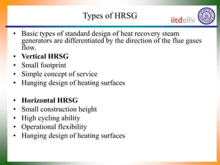
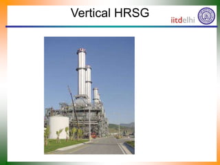
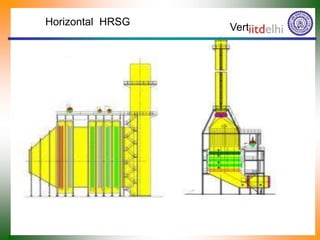
1) The basic types of HRSGs differentiated by flue gas flow direction including vertical and horizontal designs.
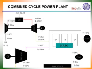
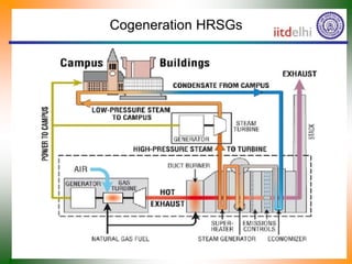
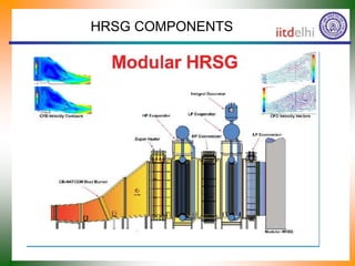
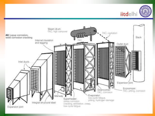
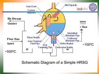
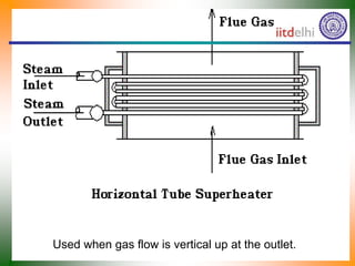
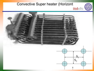
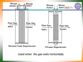
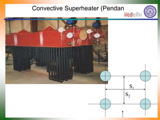
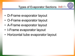
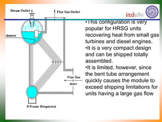
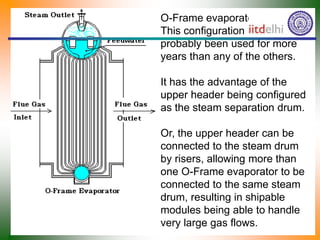
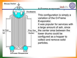
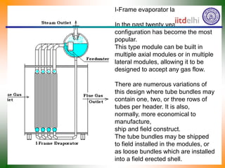
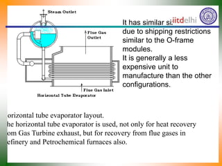
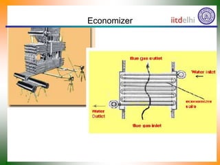
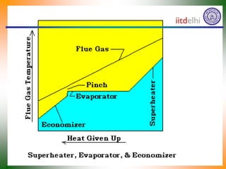
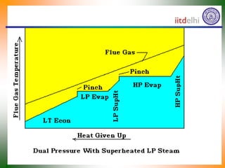
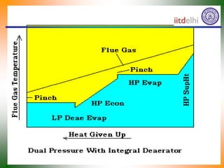
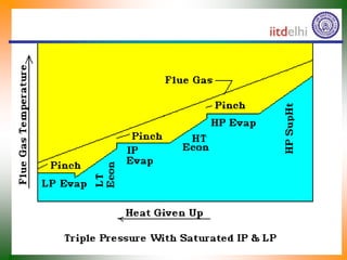
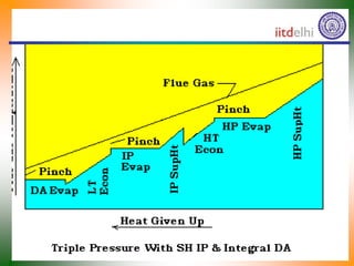
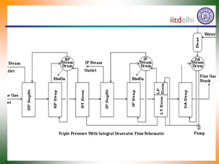
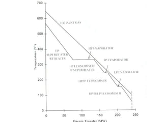
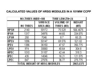
2) The main components of HRSGs including evaporator sections, superheaters, and economizers. Common configurations for these components are described.
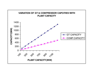
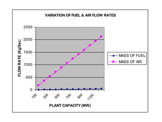
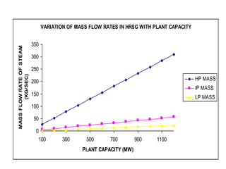
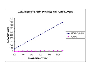
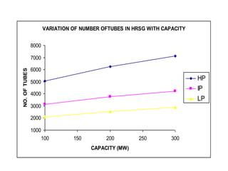
3) Charts showing how the capacities of gas turbines, compressors, steam turbines, pumps and other parameters vary with increasing plant capacity.