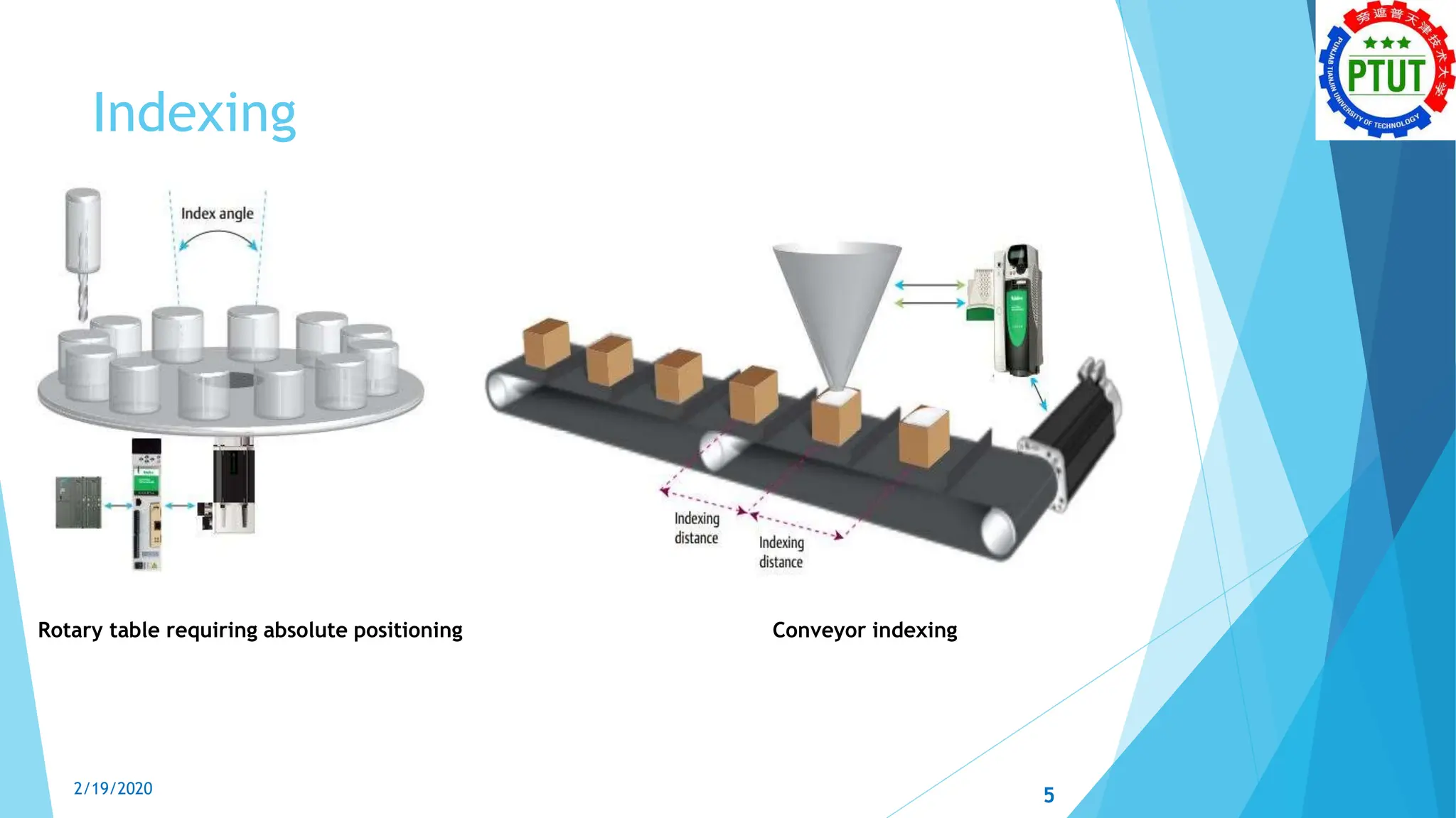
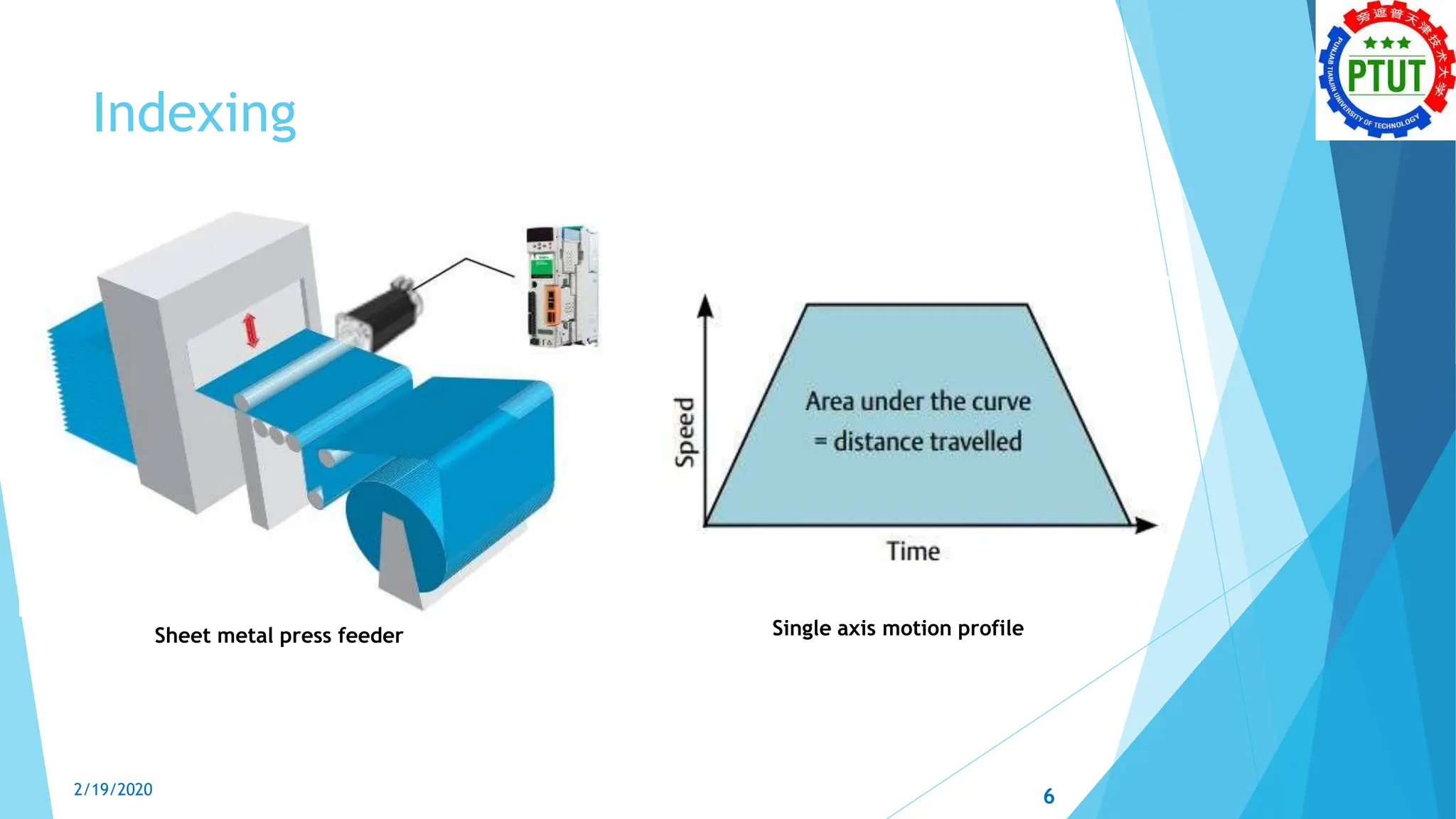
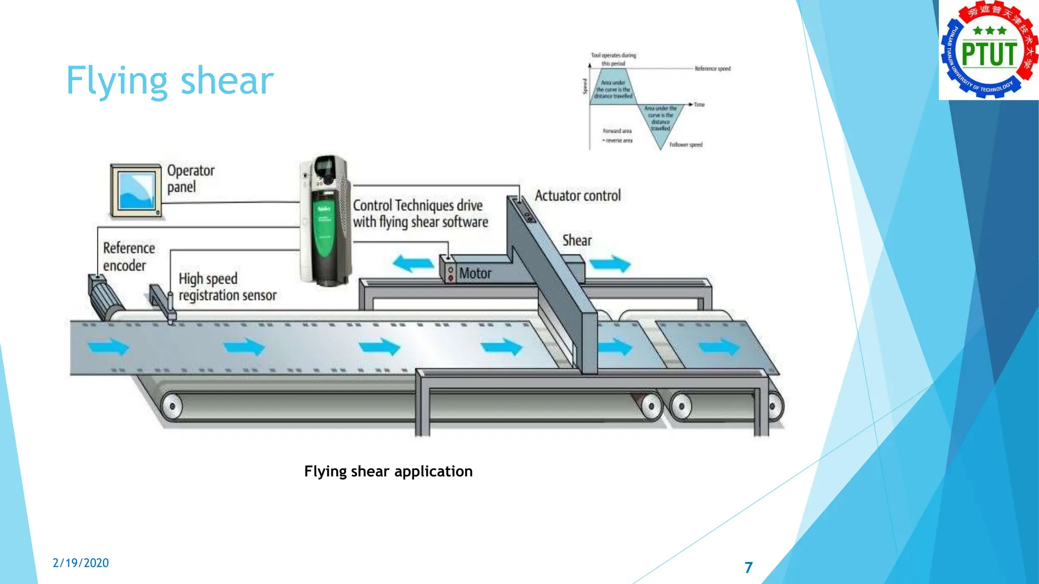
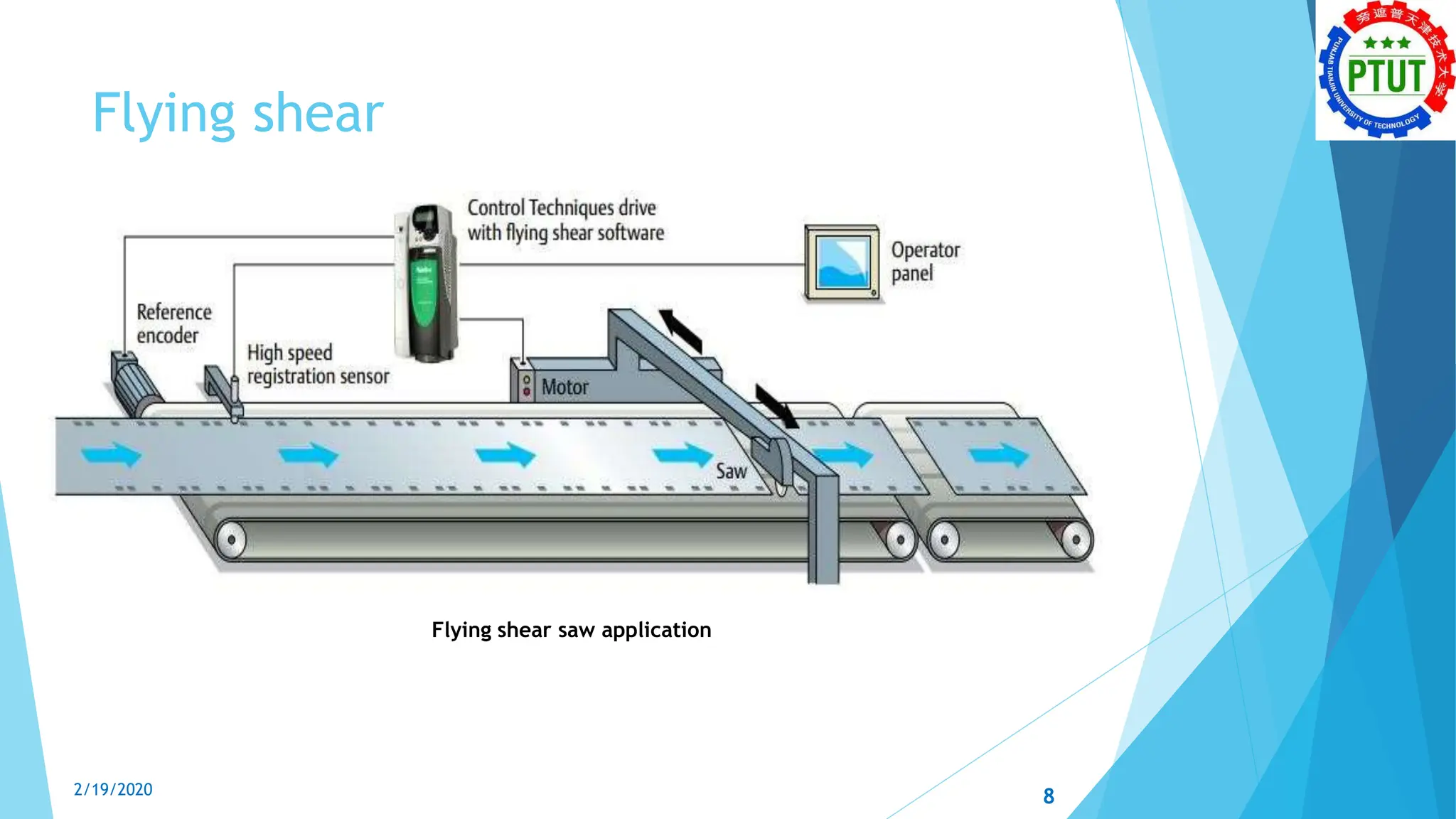
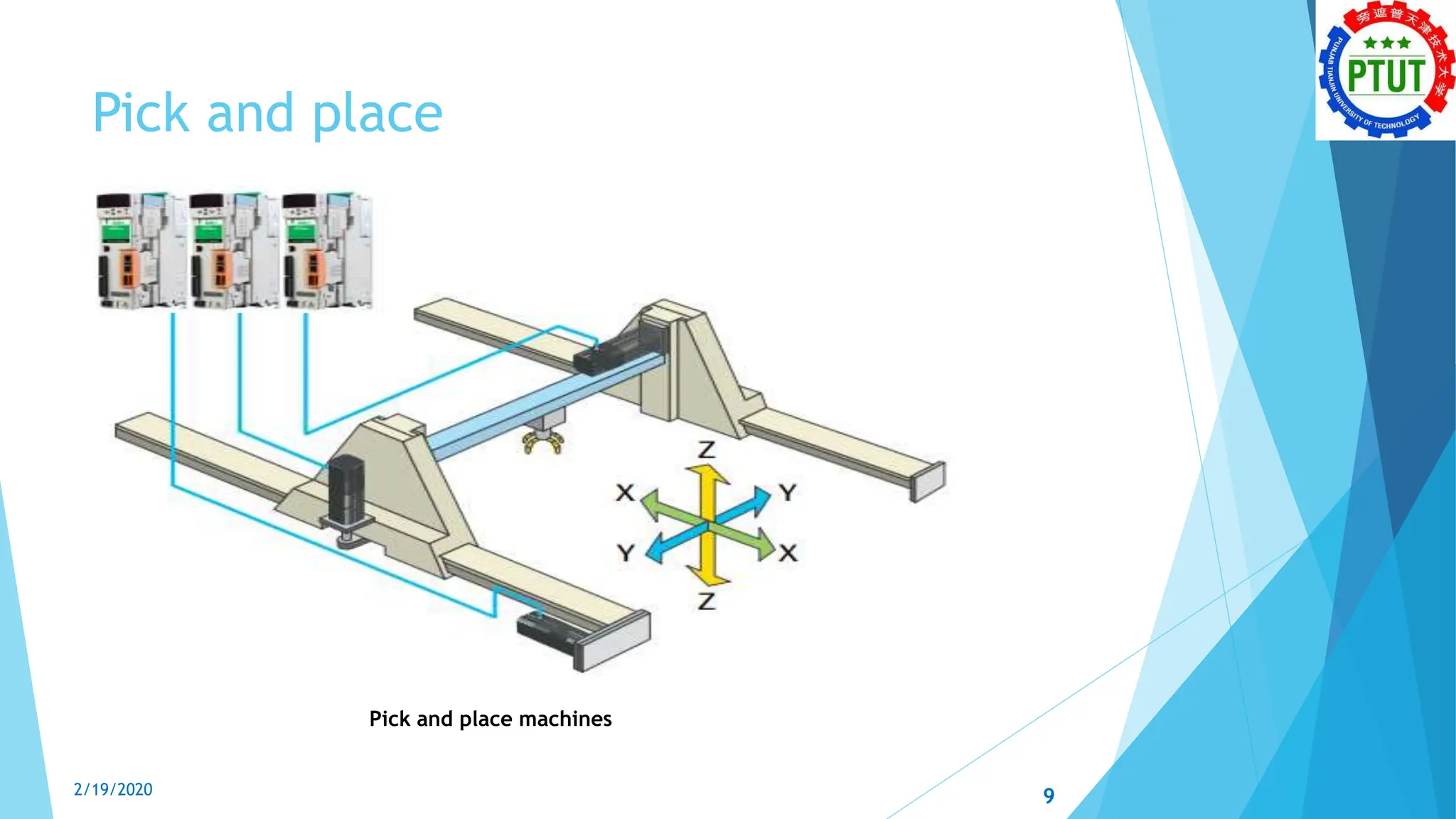
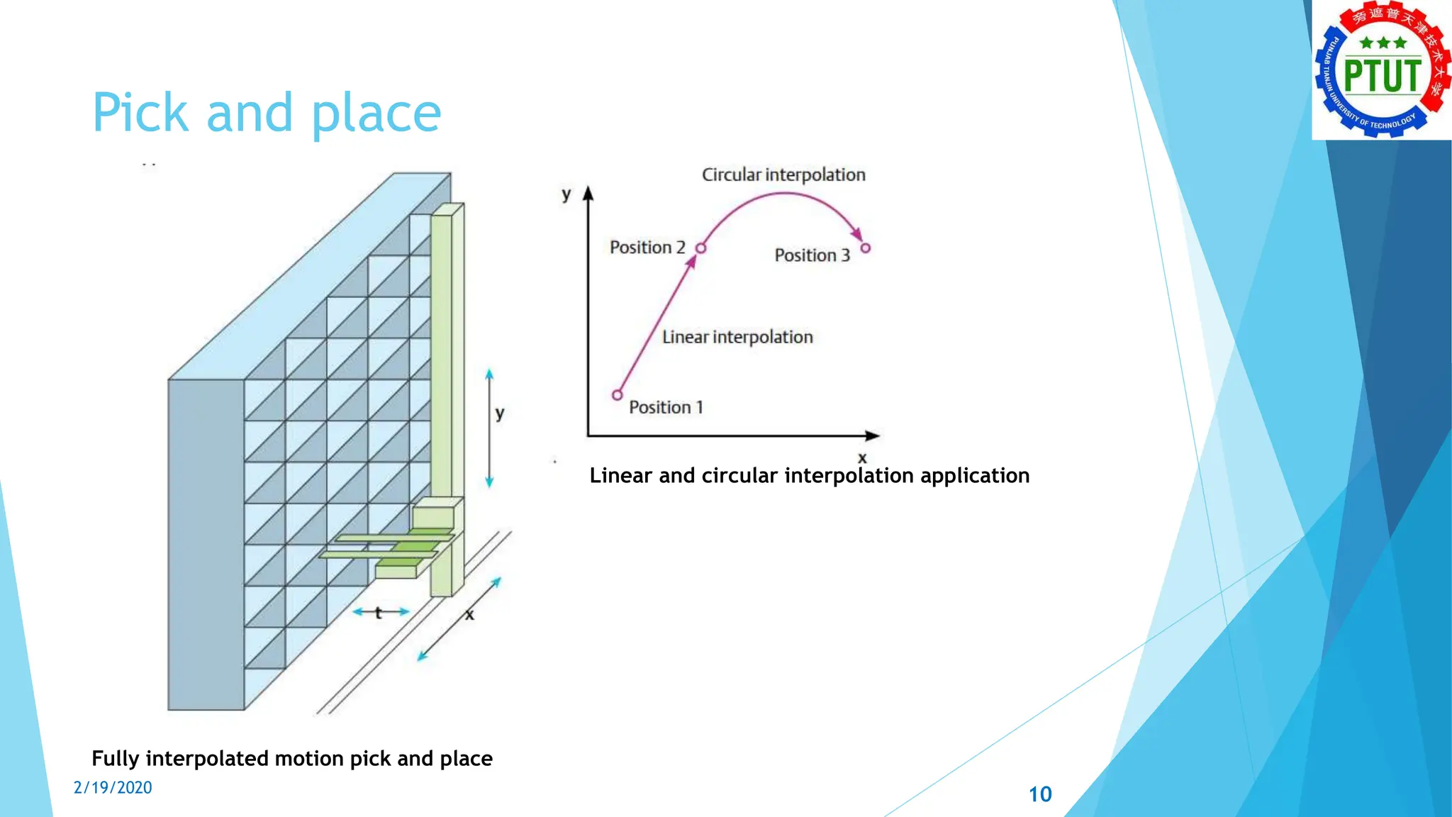
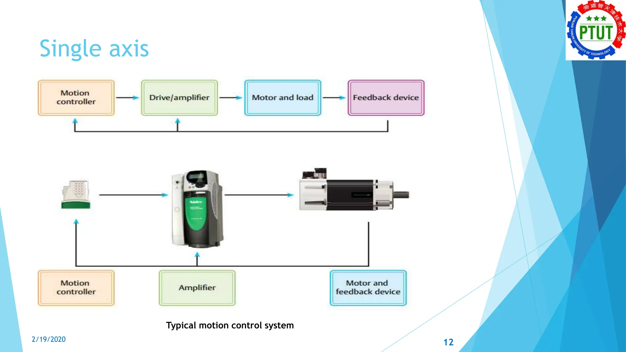
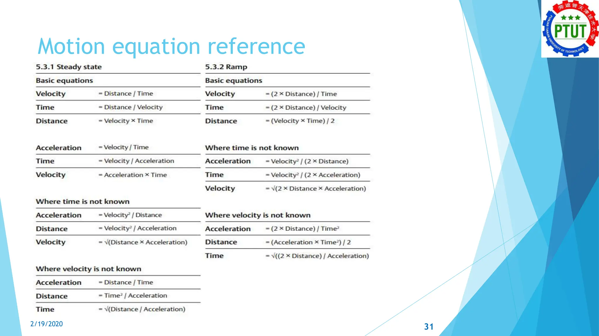
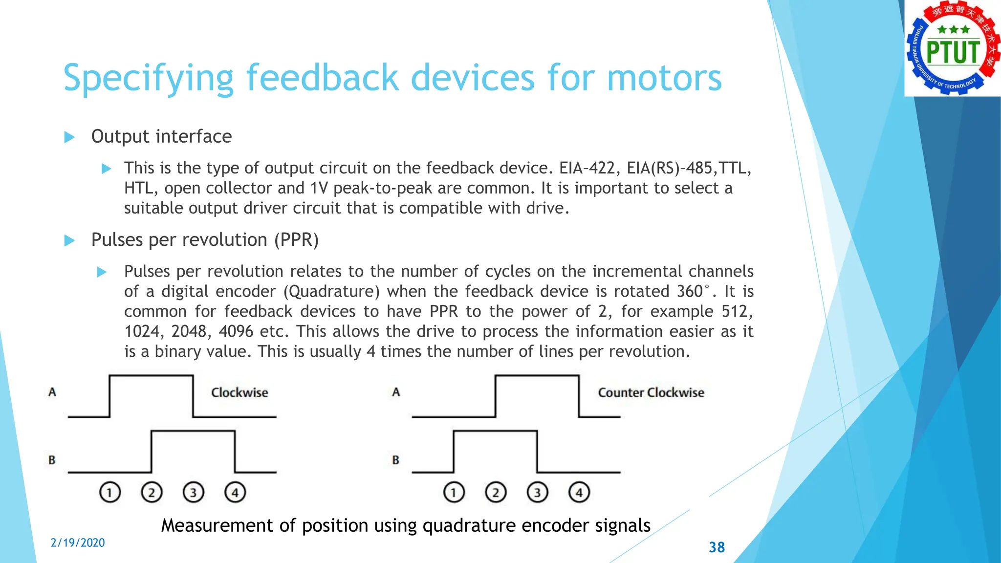
Engr. Athar Baig
Lecturer
PTUT, Lahore
2/19/2020
Electrical Technology Department
Motion Control Technologies
1
Contents
 Introduction to motion control
 Common industrial motion applications
 Motion system layout
 Relationships of motion
 Worked examples using motion equations
 Specifying feedback devices for motors
 Single axis  1.5 axis interpolation
 Degrees, minutes and seconds  Characteristics of feedback devices
 Output interface  Pulses per revolution (PPR)
 Encoder input specifications  Lines per revolution (LPR)
 Counts per revolution (CPR)
2/19/2020 2
Introduction to motion control
 Motion control is an exciting automation technology that has become the
cornerstone of modern industrial machinery design.
 It is about making a mechanism move under complete control, how you want,
when you want.
 It incorporates the finer elements of motor control and requires careful
mechanical design.
 Motion technology provides
 improved performance
 increased ease of use
 enabling servo and motion controls to be applied more widely than ever before
 greater accuracy, performance and efficiency in many production machine
applications
 Motion control technology can be applied to rotatory servo motors,
asynchronous AC and DC motors and various linear motor technologies, to
provide ever more flexible and dynamic production systems.
3
2/19/2020
Common industrial motion applications
 Motion applications call upon a varied array of engineering skills to thoroughly
understand the mechanical and control system.
 The following three examples show how motion is used in very different
applications, each requiring a different method to achieve the goal.
1. Indexing
2. Flying shear
3. Pick and place
4
2/19/2020
Indexing
5
Rotary table requiring absolute positioning Conveyor indexing
2/19/2020
Indexing
Sheet metal press feeder Single axis motion profile
6
2/19/2020
Flying shear
Flying shear application
7
2/19/2020
Flying shear
Flying shear saw application
8
2/19/2020
Pick and place
Pick and place machines
2/19/2020 9
Pick and place
Fully interpolated motion pick and place
Linear and circular interpolation application
2/19/2020 10
Motion system layout
There are two typical motion system configurations
1) Multi-axis controllers where the motion control, trajectory and
machine logic is defined by a single device
2) Decentralized where the motion controller resides within a single axis
system
2/19/2020 11
Single axis
Typical motion control system
2/19/2020 12
Single axis
 The motion profiler
 To generate the motion profile
 It defines the motion requirements of the system.
 The control and generation of the position reference is usually handled within the motion
controller.
 Discuss later in greater detail
 Position loop
 It resides within the motion controller and compares position reference with the position
feedback to determine the position error.
 Used to generate a speed demand, also known as a speed reference, to regulate the
position
 Traditionally this was transferred from the motion controller to the amplifier via an analog
signal, however this is prone to error and electrical noise.
 Today this is commonly achieved via a motion communication network such as SERCOS,
Ether CAT, PROFINET IRT; or in the case of single axis with integrated motion control it is
applied as a direct digital reference to the drive.
2/19/2020 13
Single axis
Closed loop control systems
2/19/2020 14
Single axis
 Speed loop
 The speed loop is usually integrated within the drive/amplifier. This
compares the speed demand from the position loop to the speed feedback
from the motor, and generates a torque reference. For the motion control
system to function correctly, it is important that any ramps within the drive
are fully disabled, otherwise the system will be unstable. Typical update rate
for the speed loop is usually between 250μs to 500μs.
 Torque loop
 The current loop is integrated within the drive/amplifier, and is designed to
regulate the torque producing output current to the motor. It takes the
torque demand from the speed loop, and current feedback from current
sensors within the amplifier to generate the control signals to produce a
power output from the drive. A typical update rate for a current loop is
around 62.5μs.
2/19/2020 15
Single axis
Traditional analog vs digital communications systems
2/19/2020 16
1.5 axis interpolation
An example of a reference/follower application
is a rotary knife controller
2/19/2020 17
Simple reference/follower configuration
2/19/2020 18
Relationships of motion
Distance(θ)
= velocity × time
= ∫v · dt (integral of velocity × time)
Velocity(v)
= distance / time
= dθ/dt (rate of change of distance) = ∫α
· dt (integral of acceleration × time)
Acceleration(α)
= velocity / time
= dv/dt (rate of change of velocity)
= ∫γ · dt (integral of jerk × time)
Jerk(γ)
= acceleration / time
= dα/dt (rate of change of acceleration)
2/19/2020 19
Relationships of motion
Trapezoidal position/velocity profiles
2/19/2020 20
Relationships of motion
Distance, velocity, acceleration and jerk for a trapezoidal profile
2/19/2020 21
Relationships of motion
Distance, velocity, acceleration and jerk for an S-ramp profile
2/19/2020 22
Relationships of motion
Distance, velocity, acceleration and jerk for a sine ramp profile
2/19/2020 23
Worked examples using motion equations
 The aim of this section is to show some worked motion problems in standard
industrial units, to demonstrate how easily standard trapezoidal motion
profiles can be solved.
 Constant velocity
 Constant acceleration
2/19/2020 24
Constant velocity
 If a conveyor moves at a constant speed of 5m/s for 4.5s, what distance will
be travelled?
2/19/2020 25
Constant velocity
 If a conveyor covers 7.5m in 5 seconds at a constant speed, what speed was
used?
2/19/2020 26
Constant acceleration
 If a crane picks up a load from the ground, and accelerates it up to 5m/s in
4.5 seconds, what distance will be covered?
2/19/2020 27
Constant acceleration
 If a crane picks up a load from the ground, and accelerates it at 3m/s/s or
3m/s2 for 6s, what speed was reached?
2/19/2020 28
Constant acceleration
crane picks up a load from the ground
2/19/2020 29
Constant acceleration
 If a crane picks up a load from the ground, and accelerates it at 1.5m/𝑠2
for
5s, how far will the load have travelled?
 If a crane picks up a load from the ground, and takes 4s to accelerate up to
3m/s, what was the rate of acceleration?
2/19/2020 30
Motion equation reference
2/19/2020 31
Specifying feedback devices for motors
One of the most important requirements for feedback devices used on motors is the quality of
the device itself. As with any component in a control system it is always a trade-off between cost
and quality, and feedback devices are no different.
 Degrees, minutes and seconds
 360° is equivalent to one complete revolution
 For smaller angular graduations, minutes or arc minutes are used, which is a subdivision
of a degree and like time, there are 60 minutes to a degree
 The symbol used for arc minutes is ', so for 0.5° there are 30' arc minutes. This analogy
continues, as a subdivision of an arc minute is an arc second. The symbol used for arc
second is “.
 Note – always useful to remember
 ➜ 1' arc minute = 0.0166667° (1°/60')
 ➜ 1" arc second = 0.000277778° (1°/(60' × 60"))
 Characteristics of feedback devices
 There are many features of feedback devices that effect the overall performance of a
control system that contains drives and motors. It is easy to confuse position accuracy
with position resolution and vice versa.
2/19/2020 32
Specifying feedback devices for motors
 Accuracy
 Accuracy is the most important factor for the quality of a feedback device in a
motor drive system.
 The accuracy of a feedback device is governed by many factors, some being
related to the design of the encoder and the manufacturing process, others being
the mounting arrangement.
 . This is usually quoted in terms of worst-case position error over one complete
mechanical revolution and given in arc seconds; sometimes referred to as single
cycle error.
 When considering a servo motor that has a feedback device mounted, if the
velocity of the feedback device was scoped, a trace similar to Figure 6-1 would be
seen.
 The top trace (pink) shows the marker pulse of the feedback device.
 The trace below (green) is a capture of the incremental channels of the feedback device.
The bottom trace (yellow) is the actual feedback device single cycle error.
 Close observation of the trace can see that there is a repeating pattern every marker
pulse.
2/19/2020 33
Specifying feedback devices for motors
 Resolution
 Resolution of a positional system that consists of a servo motor with a feedback
device and drive can be difficult to define. The reason for this is due partly down
to the type of feedback device selected for the application. This section considers
three identical systems with different feedback devices fitted.
 System 1 – Resolver
 A resolver feedback device is electro mechanical similar to a transformer and
generates an analog output. It does not offer any discrete positional information on
its own and needs to be converted to a digital signal. The conversion is done
onboard the drive and the resolution is determined by the number of bits in the
analog to digital converter.
 System 2 – Quadrature incremental encoder
 A quadrature incremental encoder is the most common digital feedback device.
Most encoders use optics to shine a light through a slot to indicate positional
movement. Resolution of these devices is dependent on the number of slots that
can be put on an encoder disk.
2/19/2020 34
Specifying feedback devices for motors
 Resolution
 Resolution of a positional system that consists of a servo motor with a feedback
device and drive can be difficult to define. The reason for this is due partly down
to the type of feedback device selected for the application. This section considers
three identical systems with different feedback devices fitted.
 System 3 – SinCos incremental encoder
 A SinCos incremental encoder is an analog feedback device, so does not offer any
discrete positional information on its own and needs to be converted to a digital
signal. This conversion is handled onboard the drive and is split into two items, one
being the number of LPRs and the other being the number of bits in the analog to
digital converter (number of interpolated bits).
2/19/2020 35
Specifying feedback devices for motors
Typical performance of different feedback types
2/19/2020 36
Specifying feedback devices for motors
 Mechanical misalignment
 The mounting arrangement of feedback devices is critical to the long-term success of the
motor-drive system. Mounting is needed for aligning the position of the encoder to the
position of the motor magnet relative to the motor windings. This alignment is called the
commutation angle. If the feedback device is not correctly inline with motor shaft, then
heat can be generated in the encoder bearings leading to premature failure. In severe
cases, the glass disk in the encoder can rub against the optical sensing head.
 Environment
 The environment that the feedback device has to work in is critical to the long-term
success of the system.
 There are two key factors that should be considered.
 The first factor is mechanical shock being transmitted from the load, through the motor
shaft and into the feedback device. In severe cases the glass disk within the encoder
device can shatter.
 The second factor is ambient temperature. The feedback device is in a position where
there is no airflow, so heat generated locally is not removed from the vicinity. In cases
where the temperature of the feedback device is higher than specified (100°C), issues
such as component failure or lost pulses could occur.
2/19/2020 37
Specifying feedback devices for motors
 Output interface
 This is the type of output circuit on the feedback device. EIA–422, EIA(RS)–485,TTL,
HTL, open collector and 1V peak-to-peak are common. It is important to select a
suitable output driver circuit that is compatible with drive.
 Pulses per revolution (PPR)
 Pulses per revolution relates to the number of cycles on the incremental channels
of a digital encoder (Quadrature) when the feedback device is rotated 360°. It is
common for feedback devices to have PPR to the power of 2, for example 512,
1024, 2048, 4096 etc. This allows the drive to process the information easier as it
is a binary value. This is usually 4 times the number of lines per revolution.
Measurement of position using quadrature encoder signals
2/19/2020 38
Any
Question?

Lecture 1,2 of Motion Control Technologies.pptx

  • 1.
    Engr. Athar Baig Lecturer PTUT,Lahore 2/19/2020 Electrical Technology Department Motion Control Technologies 1
  • 2.
    Contents  Introduction tomotion control  Common industrial motion applications  Motion system layout  Relationships of motion  Worked examples using motion equations  Specifying feedback devices for motors  Single axis  1.5 axis interpolation  Degrees, minutes and seconds  Characteristics of feedback devices  Output interface  Pulses per revolution (PPR)  Encoder input specifications  Lines per revolution (LPR)  Counts per revolution (CPR) 2/19/2020 2
  • 3.
    Introduction to motioncontrol  Motion control is an exciting automation technology that has become the cornerstone of modern industrial machinery design.  It is about making a mechanism move under complete control, how you want, when you want.  It incorporates the finer elements of motor control and requires careful mechanical design.  Motion technology provides  improved performance  increased ease of use  enabling servo and motion controls to be applied more widely than ever before  greater accuracy, performance and efficiency in many production machine applications  Motion control technology can be applied to rotatory servo motors, asynchronous AC and DC motors and various linear motor technologies, to provide ever more flexible and dynamic production systems. 3 2/19/2020
  • 4.
    Common industrial motionapplications  Motion applications call upon a varied array of engineering skills to thoroughly understand the mechanical and control system.  The following three examples show how motion is used in very different applications, each requiring a different method to achieve the goal. 1. Indexing 2. Flying shear 3. Pick and place 4 2/19/2020
  • 5.
    Indexing 5 Rotary table requiringabsolute positioning Conveyor indexing 2/19/2020
  • 6.
    Indexing Sheet metal pressfeeder Single axis motion profile 6 2/19/2020
  • 7.
    Flying shear Flying shearapplication 7 2/19/2020
  • 8.
    Flying shear Flying shearsaw application 8 2/19/2020
  • 9.
    Pick and place Pickand place machines 2/19/2020 9
  • 10.
    Pick and place Fullyinterpolated motion pick and place Linear and circular interpolation application 2/19/2020 10
  • 11.
    Motion system layout Thereare two typical motion system configurations 1) Multi-axis controllers where the motion control, trajectory and machine logic is defined by a single device 2) Decentralized where the motion controller resides within a single axis system 2/19/2020 11
  • 12.
    Single axis Typical motioncontrol system 2/19/2020 12
  • 13.
    Single axis  Themotion profiler  To generate the motion profile  It defines the motion requirements of the system.  The control and generation of the position reference is usually handled within the motion controller.  Discuss later in greater detail  Position loop  It resides within the motion controller and compares position reference with the position feedback to determine the position error.  Used to generate a speed demand, also known as a speed reference, to regulate the position  Traditionally this was transferred from the motion controller to the amplifier via an analog signal, however this is prone to error and electrical noise.  Today this is commonly achieved via a motion communication network such as SERCOS, Ether CAT, PROFINET IRT; or in the case of single axis with integrated motion control it is applied as a direct digital reference to the drive. 2/19/2020 13
  • 14.
    Single axis Closed loopcontrol systems 2/19/2020 14
  • 15.
    Single axis  Speedloop  The speed loop is usually integrated within the drive/amplifier. This compares the speed demand from the position loop to the speed feedback from the motor, and generates a torque reference. For the motion control system to function correctly, it is important that any ramps within the drive are fully disabled, otherwise the system will be unstable. Typical update rate for the speed loop is usually between 250μs to 500μs.  Torque loop  The current loop is integrated within the drive/amplifier, and is designed to regulate the torque producing output current to the motor. It takes the torque demand from the speed loop, and current feedback from current sensors within the amplifier to generate the control signals to produce a power output from the drive. A typical update rate for a current loop is around 62.5μs. 2/19/2020 15
  • 16.
    Single axis Traditional analogvs digital communications systems 2/19/2020 16
  • 17.
    1.5 axis interpolation Anexample of a reference/follower application is a rotary knife controller 2/19/2020 17
  • 18.
    Simple reference/follower configuration Simplereference/follower configuration 2/19/2020 18
  • 19.
    Relationships of motion Distance(θ) =velocity × time = ∫v · dt (integral of velocity × time) Velocity(v) = distance / time = dθ/dt (rate of change of distance) = ∫α · dt (integral of acceleration × time) Acceleration(α) = velocity / time = dv/dt (rate of change of velocity) = ∫γ · dt (integral of jerk × time) Jerk(γ) = acceleration / time = dα/dt (rate of change of acceleration) 2/19/2020 19
  • 20.
    Relationships of motion Trapezoidalposition/velocity profiles 2/19/2020 20
  • 21.
    Relationships of motion Distance,velocity, acceleration and jerk for a trapezoidal profile 2/19/2020 21
  • 22.
    Relationships of motion Distance,velocity, acceleration and jerk for an S-ramp profile 2/19/2020 22
  • 23.
    Relationships of motion Distance,velocity, acceleration and jerk for a sine ramp profile 2/19/2020 23
  • 24.
    Worked examples usingmotion equations  The aim of this section is to show some worked motion problems in standard industrial units, to demonstrate how easily standard trapezoidal motion profiles can be solved.  Constant velocity  Constant acceleration 2/19/2020 24
  • 25.
    Constant velocity  Ifa conveyor moves at a constant speed of 5m/s for 4.5s, what distance will be travelled? 2/19/2020 25
  • 26.
    Constant velocity  Ifa conveyor covers 7.5m in 5 seconds at a constant speed, what speed was used? 2/19/2020 26
  • 27.
    Constant acceleration  Ifa crane picks up a load from the ground, and accelerates it up to 5m/s in 4.5 seconds, what distance will be covered? 2/19/2020 27
  • 28.
    Constant acceleration  Ifa crane picks up a load from the ground, and accelerates it at 3m/s/s or 3m/s2 for 6s, what speed was reached? 2/19/2020 28
  • 29.
    Constant acceleration crane picksup a load from the ground 2/19/2020 29
  • 30.
    Constant acceleration  Ifa crane picks up a load from the ground, and accelerates it at 1.5m/𝑠2 for 5s, how far will the load have travelled?  If a crane picks up a load from the ground, and takes 4s to accelerate up to 3m/s, what was the rate of acceleration? 2/19/2020 30
  • 31.
  • 32.
    Specifying feedback devicesfor motors One of the most important requirements for feedback devices used on motors is the quality of the device itself. As with any component in a control system it is always a trade-off between cost and quality, and feedback devices are no different.  Degrees, minutes and seconds  360° is equivalent to one complete revolution  For smaller angular graduations, minutes or arc minutes are used, which is a subdivision of a degree and like time, there are 60 minutes to a degree  The symbol used for arc minutes is ', so for 0.5° there are 30' arc minutes. This analogy continues, as a subdivision of an arc minute is an arc second. The symbol used for arc second is “.  Note – always useful to remember  ➜ 1' arc minute = 0.0166667° (1°/60')  ➜ 1" arc second = 0.000277778° (1°/(60' × 60"))  Characteristics of feedback devices  There are many features of feedback devices that effect the overall performance of a control system that contains drives and motors. It is easy to confuse position accuracy with position resolution and vice versa. 2/19/2020 32
  • 33.
    Specifying feedback devicesfor motors  Accuracy  Accuracy is the most important factor for the quality of a feedback device in a motor drive system.  The accuracy of a feedback device is governed by many factors, some being related to the design of the encoder and the manufacturing process, others being the mounting arrangement.  . This is usually quoted in terms of worst-case position error over one complete mechanical revolution and given in arc seconds; sometimes referred to as single cycle error.  When considering a servo motor that has a feedback device mounted, if the velocity of the feedback device was scoped, a trace similar to Figure 6-1 would be seen.  The top trace (pink) shows the marker pulse of the feedback device.  The trace below (green) is a capture of the incremental channels of the feedback device. The bottom trace (yellow) is the actual feedback device single cycle error.  Close observation of the trace can see that there is a repeating pattern every marker pulse. 2/19/2020 33
  • 34.
    Specifying feedback devicesfor motors  Resolution  Resolution of a positional system that consists of a servo motor with a feedback device and drive can be difficult to define. The reason for this is due partly down to the type of feedback device selected for the application. This section considers three identical systems with different feedback devices fitted.  System 1 – Resolver  A resolver feedback device is electro mechanical similar to a transformer and generates an analog output. It does not offer any discrete positional information on its own and needs to be converted to a digital signal. The conversion is done onboard the drive and the resolution is determined by the number of bits in the analog to digital converter.  System 2 – Quadrature incremental encoder  A quadrature incremental encoder is the most common digital feedback device. Most encoders use optics to shine a light through a slot to indicate positional movement. Resolution of these devices is dependent on the number of slots that can be put on an encoder disk. 2/19/2020 34
  • 35.
    Specifying feedback devicesfor motors  Resolution  Resolution of a positional system that consists of a servo motor with a feedback device and drive can be difficult to define. The reason for this is due partly down to the type of feedback device selected for the application. This section considers three identical systems with different feedback devices fitted.  System 3 – SinCos incremental encoder  A SinCos incremental encoder is an analog feedback device, so does not offer any discrete positional information on its own and needs to be converted to a digital signal. This conversion is handled onboard the drive and is split into two items, one being the number of LPRs and the other being the number of bits in the analog to digital converter (number of interpolated bits). 2/19/2020 35
  • 36.
    Specifying feedback devicesfor motors Typical performance of different feedback types 2/19/2020 36
  • 37.
    Specifying feedback devicesfor motors  Mechanical misalignment  The mounting arrangement of feedback devices is critical to the long-term success of the motor-drive system. Mounting is needed for aligning the position of the encoder to the position of the motor magnet relative to the motor windings. This alignment is called the commutation angle. If the feedback device is not correctly inline with motor shaft, then heat can be generated in the encoder bearings leading to premature failure. In severe cases, the glass disk in the encoder can rub against the optical sensing head.  Environment  The environment that the feedback device has to work in is critical to the long-term success of the system.  There are two key factors that should be considered.  The first factor is mechanical shock being transmitted from the load, through the motor shaft and into the feedback device. In severe cases the glass disk within the encoder device can shatter.  The second factor is ambient temperature. The feedback device is in a position where there is no airflow, so heat generated locally is not removed from the vicinity. In cases where the temperature of the feedback device is higher than specified (100°C), issues such as component failure or lost pulses could occur. 2/19/2020 37
  • 38.
    Specifying feedback devicesfor motors  Output interface  This is the type of output circuit on the feedback device. EIA–422, EIA(RS)–485,TTL, HTL, open collector and 1V peak-to-peak are common. It is important to select a suitable output driver circuit that is compatible with drive.  Pulses per revolution (PPR)  Pulses per revolution relates to the number of cycles on the incremental channels of a digital encoder (Quadrature) when the feedback device is rotated 360°. It is common for feedback devices to have PPR to the power of 2, for example 512, 1024, 2048, 4096 etc. This allows the drive to process the information easier as it is a binary value. This is usually 4 times the number of lines per revolution. Measurement of position using quadrature encoder signals 2/19/2020 38
  • 39.

Editor's Notes

  • #4 https://circuitglobe.com/difference-between-synchronous-and-asynchronous-motor.html
  • #6 https://www.youtube.com/watch?v=XYTn1qJ_8vU, https://www.youtube.com/watch?v=H8W5MrW6UJA