
Recommended
More Related Content
Similar to Portal Imaging used to clear setup uncertainty
Similar to Portal Imaging used to clear setup uncertainty (20)
Recently uploaded
Recently uploaded (20)
Portal Imaging used to clear setup uncertainty
- 2. Goal of Radiation therapy Deliver a prescribed radiation dose to the target volume accurately while sparing the surrounding normal and critical structures
- 3. goal of radiotherapy High-precision RT try to spread these curves apart
- 4. • Small changes in the doses of 7 % to 15 % can reduce tumour control significantly or increase rate of normal tissue complications • ICRU 50 Recommendations Accuracy in dose delivery +/- 5 % Only if field placement is precise during entire course
- 5. • Compromise in Geometric accuracy = geographical mess • Discrepancies occur frequently esp. complicated setups • Influence outcome of treatment • Reduced by frequent monitoring of patient positioning • Several studies suggest patient position to be checked daily
- 6. Trends in radiation oncology • Steep dose gradients; 90%-30% over 3mm • Typically narrow margins around GTV
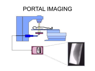
- 7. • Efforts to develop more convenient methods to image the patient during radiation treatment ,the process known as portal imaging • Aim : verify that radiation portal delivered is same as that prescribed ( by imaging the portal during radiation)
- 11. Physics • Contrast :result of differences in x- ray attenuation ;describes how much a object stands out from its surroundings • Photoelectric effect dominates at lower energies which is proportional to the atomic number • at higher energies Compton effect predominates which is dependent on the the electron density
- 12. Signal to noise ratio Detectability of object depends not only on how large the difference in attenuation is b/n the object and the surroundings But also on how large this signal is compared to the uncertainty in the signal Quantum efficiency Measure of how efficient the imaging system is at transferring the information contained in the radiation beam incident upon the detector Spatial resolution Measure of how the image signal is blurred by the imaging system
- 13. Problems with a port film • Time consuming • Labor intensive • Reduce throughput in a busy department • Quantitative interpretation of geometric discrepancies is difficult and tedious to perform
- 14. Electronic portal imaging devices • Since 1980’s • Two categories • Scanning systems :radiation detector subtends only a small fraction of the radiation beam • Area systems: entire area
- 15. Matrix ion chamber • Two sets of electrodes (256 wires each) that are oriented perpendicular (matrix) to each other separated by a 0.8 mm gap which is filled with a fluid (2,2,4-trimetyl pentane ; a.k.a liquid on chamber )which is ionized when the device is irradiated
- 16. Adv Compact size Geometric reliability Less time 5.5 s to read out an image Disadv Only 1 electrode active at a time higher doses required to generate images sensitivity of each chamber varies - spurious signals Susceptible to artifacts - dose rate changes
- 17. Camera based EPID’s • Metal plate and a phospur (gd2O2S) screen viewed b a camera using a 45 degree mirror • Major limitation : light collecting efficiency of the system reduces image quality
- 20. Commissioning and QA Mechanical stability Electrical stability Calibration Dose control Image quality Software analysis
- 21. Clinical application Primary application • Verification of patient set up • Assessment of target and organ motion
- 22. EPID IMPLEMENTATION • Certain specific goals and protocols for the use of EPIDs must be established before they are succesfully brought into the clinic • Questions to be discussed before implementation ??????
- 23. WHAT IS THE PUPOSE /AIM OF INSTALLING EPID IN THE CLINIC ? • simple film replacement/routine QA • Accurate and efficient patient set up and repositioning • Asses random and systematic errors in treatment • Inter and intra fraction motion studies
- 24. • Inter fraction errors • Occur when two radiation treatments are compared • Intra fraction errors • Occur in one radiation treatment
- 25. Systematic () and Random Errors () 0 Displacement over days Pt. 1 2 3 4 0 Mean displacement Systematic error for patient #1 Pt. 1 2 3 4 Random errors for patient #1 0 Subtract daily displacements from mean displacement Pt. 1 2 3 4 0 Pt.1 2 3 4 Compute SD of means of different patients Population () systematic error 0 Pt. 1 2 3 4 Compute SD of random errors Population () random error -5mm +5mm 0mm Pt. 1 2 3 4 Displacement, 1st day
- 26. • What is the frequency of imaging ? • Weekly • Daily • Depending on site or patient • Dependent on the statistics of set p error or decision rules
- 27. • What image acquisition modes are available on the EPID ? • Single exposure • Multiple exposure • Movie loops
- 28. • Single exposure :Single image is applied for a short period of time typically at the start of treatment • double exposure: one single exposure image and one open film are combined using a weighted sum to produce a single image • Movie loops :continuous images or online fluroscopy
- 29. • What is the choice of reference image ? • DRR • Conventional simualtion film • First approved EPID image
- 30. • When will you intervene /adjust setup? • Offline interfraction correction: where image data are acquired and reviewed ,analysed and acted on at later time Eq.weekly portal filming using hard copy • Online intrafraction correction acquiring image data ,doing analysis and taking action during the fraction the patient is treated
- 31. • What image analysis protocol will be used ? • Visual inspection only • Manual tools • Semi automated • Automated
- 32. • How will EPID system communicate with existing systems (simulator, TPS,PACS)? • Digital image communication (DI COM) • Proprietary tools
- 33. • Which patients will EPID used on for treatment verification ? • All patients • Special cases that are difficult to set up • Specific disease site
- 34. Software tools • Image acquisition • Image enhancement tools image can be manipulated to improve landmark visibility and image interpretation 1.Contrast enhancement 2.Non linear mapping of pixel values within th image based on redistributing intensity values to normalize the shape of intensity histogram 3.High pass filter :convolution of a filter and image to produce the feature enhanced image
- 35. Image registration tools • Interactive registration :use of computer graphics that allow users to overlay one image on the top of another and interactively translate ,rotate and scale the overlaid image until the anatomic features in both images coincide • Most commonly used :line drawing technique
- 44. Point pair registration • Identify locations of common anatomical landmarks on the simulator and portal images • Co-ordinates on portal image can be transformed until they best match co-ordinates on simulator image • Points / Curves • Anatomical landmarks • External fiducial markers • Implanted fiducial markers
- 45. • Cross - correlation • Hybrid registration /Chamfer matching Involves registrating a drawing generated from a simulator film with a cost function image generated from portal image The goodness of fit between the drawing and cost function is assessed by determining the cost or penalty for the drawing being at a specific location with specific orientation and scale to the cost function image
- 46. • 1.line drawing created from simulator film • 2.portal film processed using a edge detection algorithm to identify edges of anatomical structures • 3.extraction image generated • 4.transformation of this yields cost function image which is used to determine the best match
- 47. EPID CLINICAL PROTOCOL 1.For each patient ,enter patient Demographic data ,Field data and also image acquisition single/double exposure data If EPID part of integrated information system,data automatically input 2. With patient in treatment position and with appropriate immobilizing device EPID is put in imaging position
- 48. Patient and field selected and acquisition parameters loaded Image the patient with aprropriate monitor units(4 + 4 MU for double exposure ) before the treatment As protocol directs ,take a action which may include doing nothing ,performing online or offline correction If EPID is a part of the information system ,recording ,storing and retrieving the image may be simplified
- 49. Offline EPID use 1.Simple offline – to replace weekly port film, used to generate a hard copy Benefts –faster ,image enhancement Error detection done manually 2.Monitoring type –shows cumulative effect of daily FPE on course of radiotherapy in individual patient To determine time trends Movie loops for target and normal organ motion
- 50. 3.Statistical models /decision rules From the inaccuracies ,immobilization techniques can be modified Appropriate margin of PTV can be decided
- 51. Margin Recipes for generating PTV Several recipes; the ‘Dutch’ recipe is most common An assessment of the standard deviation of the systematic error (setup) and the standard deviation of the random error (setup ) is required • CTV to PTV margin may be given by 2 + 0.7 (Stroom ) or 2.5 + 0.7 (van Herk) • These generally guarantee that there is a 90% probability that 99% of the CTV will be encompassed by 95% isodose (assuming that the PTV is encompassed by the 95% isodose!) • This sort of margin expansion may not be always feasible in the context of organs at risk, and so, require an element of judgment
- 52. Online EPID USE • Allows reduction of both random and sysytematic errors but doesn’t differentiate between them • Results of studies -50 % of initail fields are judged in error and corrected • Rate of correction is anatomical site dependent and observer dependent • Final offline analysis -15 % of setups still in error by more than 5 mm
- 53. ADVANCED APPLICATIONS 1.TREATMENT QA 2.EXIT DOSIMETRY 3.ELECTRON BEAM DOSIMETRY