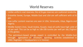
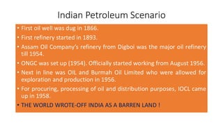
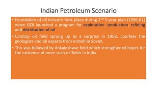
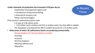
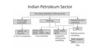
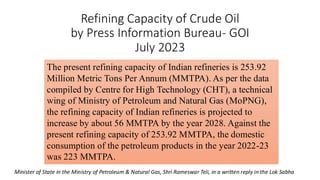
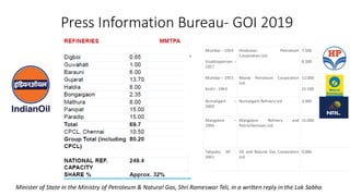
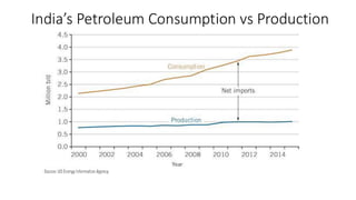
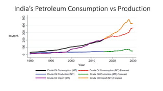
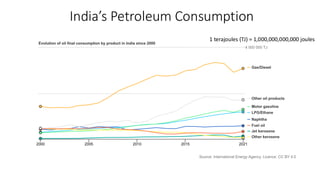
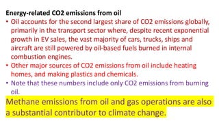
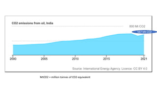
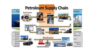
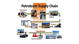
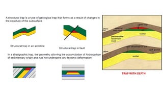
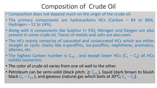
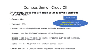
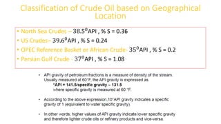
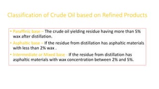
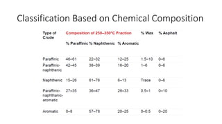
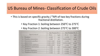
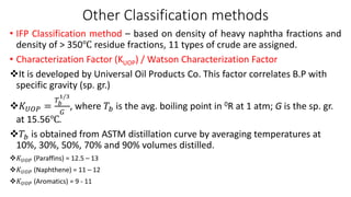
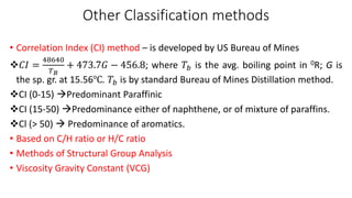
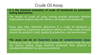
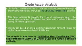
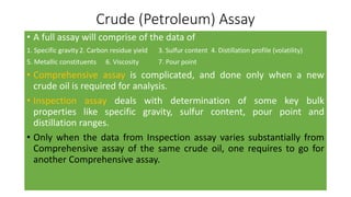
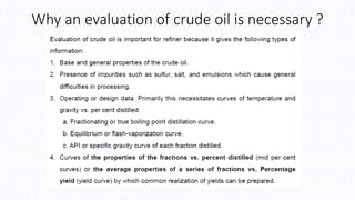
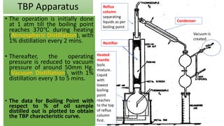
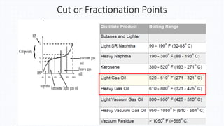
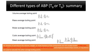
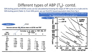
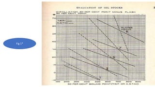
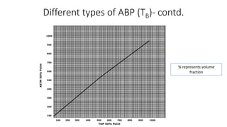
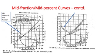
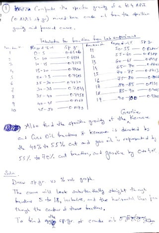
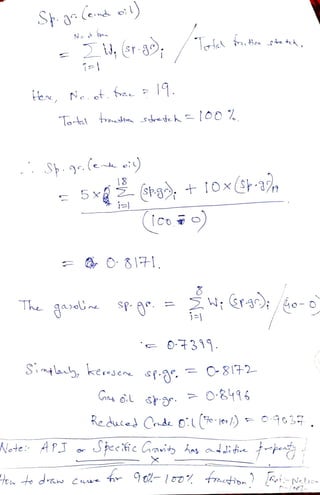
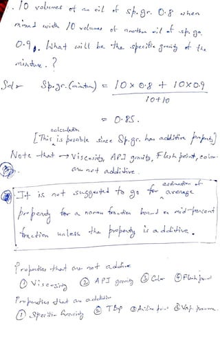
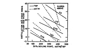
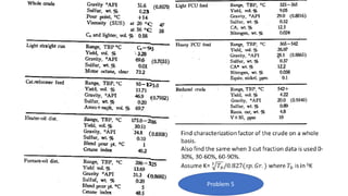
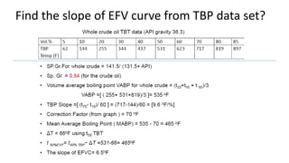
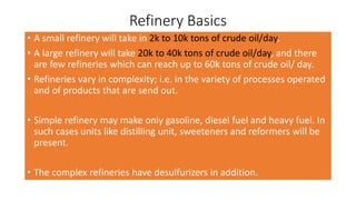
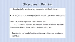
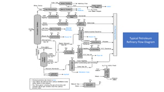
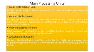
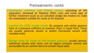
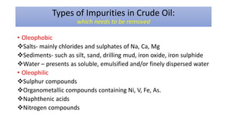
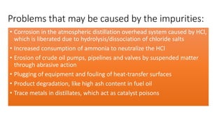
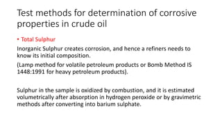
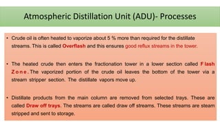
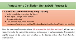
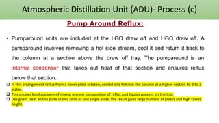
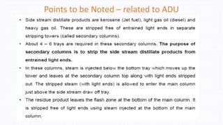
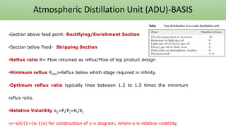
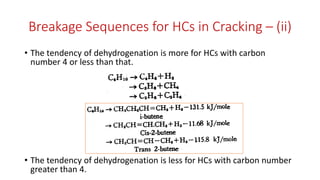
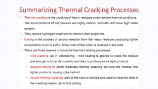
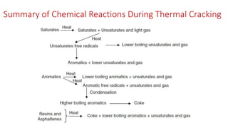
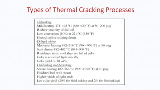
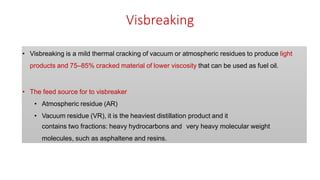
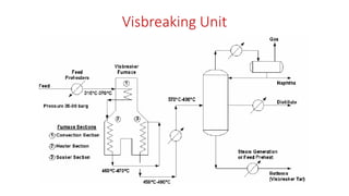
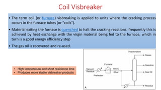
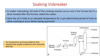
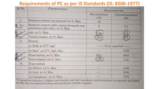
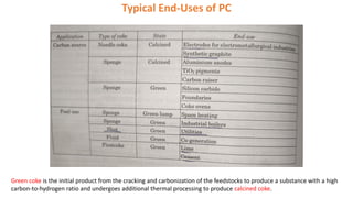
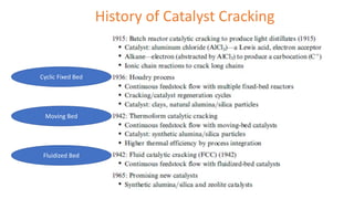
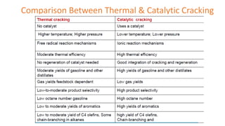
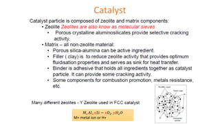
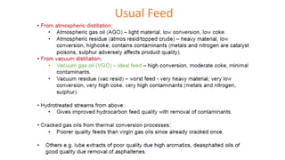
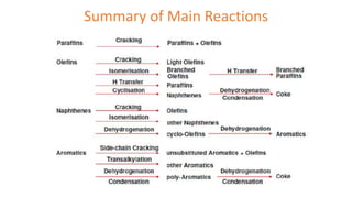
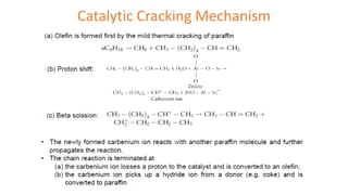
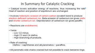
Petroleum Refining
Operations and Processing
CH3022D
By-
Aniruddha Sanyal
Assistant Professor
Department of Chemical Engineering
National Institute of Technology Calicut
Kozhikode 673601, Kerala, India.
PETROLEUM INTRODUCTION
What about the energy content of some
among these fossil fuels ?
= 55 MJ/kg
What are the major constituents of Natural Gas ??
History of Global Oil & Gas industries
• Before Oil & Gas petroleum, Coal oil and Sperm Oil were used as
common burner fuels.
• According to USA-based researchers, Edwin Drake drilled world’s first
oil well in 1859.
• The first petroleum refinery industry was set in Pasadena (Titusville)
in 1860, which belonged to William Barnsdall and William Abbott.
• There are evidences of petroleum being distilled in Russia in 1735.
World Reserves
• Unlike uniform coal reserves, the oil & gas reserves are scattered randomly.
• Erstwhile Soviet, Europe, Middle East and USA are self sufficient with oil &
gas.
• Low sulfur content reserves are seen in USA, Venezuela, Libya, Nigeria and
Algeria.
• Middle Eastern (Iran, Saudi Arabia, Kuwait, Iraq) oil wells have high yield of
oil per well. This can be as high as 10k-20k tonnes per well per day (highest
in the globe).
• The petroleum-based energy export is controlled by the Middle-East
through Organization of Petroleum Exporting Countries (established in
1960, Baghdad--> Headquarters is in Vienna).
Units of Oil in terms of Measurements
• 1 barrel (oil) = 42 US gallons = 158.97 liters
• 1 US gallon = 3.785 liters
• 1 bbl = 1 barrel of crude oil = 1 barrel (oil)
• 1 metric ton = 1000 kilograms
Oil Barrel
World Economy Scenario
• Saudi Arabia is currently world’s largest oil exporter, earning USD 236
billion, accounting for 16.7% of global crude exports. They are exporting
7.34 million barrels per day of oil.
• Russia and Canada are in the second and third position respectively for the
year 2022. India & China stands at rank 115 & 116 in terms of oil export !!
• “China is the largest importer of oil, which costs around USD 287 billion.
India stands in the third position, importing oil of the amount USD 170
billion”- OUR POLICY MAKERS ARE HENCE DESPERATE ABOUT RENEWABLE
ENERGY !
• According to International Energy Agency, 80% of the global energy
demands will be supplied from oil & gas industries in 2024. The demand is
every increasing !!
World Economy Scenario
• As on 2022, the world has around 1.56 trillion barrels of proven crude
oil reserves, not including oil sands. This is 46.6 times the world’s
annual oil consumption.
• According to OPEC Annual Statistical Bulletin 2023, 79.5% of the
reserves are from 12 OPEC member countries.
Indian Petroleum Scenario
• First oil well was dug in 1866.
• First refinery started in 1893.
• Assam Oil Company’s refinery from Digboi was the major oil refinery
till 1954.
• ONGC was set up (1954). Officially started working from August 1956.
• Next in line was OIL and Burmah Oil Limited who were allowed for
exploration and production in 1956.
• For procuring, processing of oil and distribution purposes, IOCL came
up in 1958.
• THE WORLD WROTE-OFF INDIA AS A BARREN LAND !
Indian Petroleum Scenario
• Foundation of oil industry took place during 2nd 5-year plan (1956-61)
when GOI launched a program for exploration, production, refining
and distribution of oil.
• Cambay oil field sprung up as a surprise in 1958, courtesy the
geologists and oil experts from erstwhile Soviet.
• This was followed by Ankaleshwar field which strengthened hopes for
the existence of more such oil fields in India.
•India's domestic oil production has increased 3-5%/year due to
•exploration of prospective regions and
• introduction of directional drilling,
• ehanced oil recovery, and
•other new technologies.
•The country's sedimentary basins cover
• A total of 3.36 million sq km
• 1.63 million sq km onshore and 0.41 in shallow water less than 400-m isobath.
•Its deepwater area beyond the 400-m isobath accounts for 1.32 million sq km.
• •Only seven of India's 26 sedimentary basins are producing commercially:
•Assam-Arakhan (1st discovered basin in India)
•Cambay
•Cauvery.
•Krishna-Godavari
•Mumbai offshore and
•Rajasthan.
In Recent
Times
Indian Petroleum Sector
The net increase in crude oil throughput has been 204.12 MMTPA in FY 2012 to 241.7 MMTPA in FY 2022.
Indian Oil Corporation Limited
Refineries
1. Digboi Refinery (Upper Assam)
2. Guwahati Refinery (Assam)
3. Barauni Refinery
4. Haldia Refinery
5. Mathura Refinery
6. Panipat Refinery
7. Bongaigaon Refinery
8. Gujarat Refinery (Near Ahmedabad)
Reliance Group
I . Petroleum Refining and Marketing business
(Jamnagar)
2. Petrochemicals business (Baroda)
3. Oil and Gas Exploration and Production business
(Dahej)
4. Others (Hazira)
RIL Jamnagar has the world’s largest refinery with a crude processing capacity of 1.2 million barrels per day.
Indian Petroleum Sector
Oil and Gas Exploration: Dominated by ONGC, OIL, RIL and Cairn companies
Refinery and Marketing: This has three further classifications
1. Pure Refineries with companies like CPCL, KRL, BRPL, NRL and MRPL.
2. Refined Products with company with only sells refined oil products.
3. Integrated Refining and Marketing: This section is led by IOC, HPCL, BPCL,
RIL and Essar. Natural Gas distribution: The distribution is done by
companies like GAIL, Gujarat Gas, RIL, GSPC and Mahanagar Gas.
1.CPCL: Chennai Petroleum Corporation Ltd
1.Products : Diesel, kerosene, LPG, Petrochemicals, Petrol
2.Parent: IOC; the crude throughput for 2023-24 -11.64 million metric tonnes (MMTPA)
2.KRL, BPCL-KRL
1.Products : Benzene, Toluene, White Spirit, Poly Iso-Butene and Sulphur
2.Parent: BPCL; The crude throughput–15.5 million metric tonnes (MMTPA)
3.BRPL (Now it is IOCL Bongaigaon Refinery),
1.Products : Natural gas, Petrochemicals, Petroleum
2.Parent: IOC; the crude throughput -6 million metric tonnes (MMTPA)
4.NRL (Numaligarh refinery)
1.Products : Petroleum
2.Parent: BPCL; the crude throughput -3 million metric tonnes (MMTPA)
5.MRPL
1.Products :Natural gas, Petrochemicals, Petroleum
2.Parent: ONGC; the crude throughput -15 million metric tonnes (MMTPA)
MAJOR REFINERY COMPANIES IN INDIA
Crude throughput- The amount of crude oil that enters a refinery each day to be processed into various products.
Refining Capacity of Crude Oil by Press Information
Bureau- GOI 2022
Minister of State in the Ministry of Petroleum & Natural Gas, Shri Rameswar Teli, in a written reply in the Lok Sabha
There are total 23 refineries with a total
refining capacity of 249.22 million metric
tons per annum (MMTPA). Out of these
23 refineries, 8 refineries are integrated
with Petrochemicals as per the details
given as below. 18 refineries are under
PSUs, 3 under private sectors and 2 under
joint venture.
Refining Capacity of Crude Oil
by Press Information Bureau- GOI
July 2023
The present refining capacity of Indian refineries is 253.92
Million Metric Tons Per Annum (MMTPA). As per the data
compiled by Centre for High Technology (CHT), a technical
wing of Ministry of Petroleum and Natural Gas (MoPNG),
the refining capacity of Indian refineries is projected to
increase by about 56 MMTPA by the year 2028. Against the
present refining capacity of 253.92 MMTPA, the domestic
consumption of the petroleum products in the year 2022-23
was 223 MMTPA.
Minister of State in the Ministry of Petroleum & Natural Gas, Shri Rameswar Teli, in a written reply in the Lok Sabha
Press Information Bureau- GOI 2019
Minister of State in the Ministry of Petroleum & Natural Gas, Shri Rameswar Teli, in a written reply in the Lok Sabha
Mumbai – 1954 Hindustan Petroleum
Corporation Ltd.
7.500
Visakhapatnam –
1957
8.300
Mumbai – 1955 Bharat Petroleum Corporation
Ltd.
12.000
Kochi - 1963 15.500
Numaligarh –
2000
Numaligarh Refinery Ltd. 3.000
Mangalore –
1996
Mangalore Refinery and
Petrochemicals Ltd.
15.000
Tatipaka, AP -
2001
Oil and Natural Gas Corporation
Ltd.
0.066
India’s Petroleum Consumption vs Production
MMTPA
India’s Petroleum Consumption
1 terajoules (TJ) = 1,000,000,000,000 joules
Energy-related CO2 emissions from oil
• Oil accounts for the second largest share of CO2 emissions globally,
primarily in the transport sector where, despite recent exponential
growth in EV sales, the vast majority of cars, trucks, ships and
aircraft are still powered by oil-based fuels burned in internal
combustion engines.
• Other major sources of CO2 emissions from oil include heating
homes, and making plastics and chemicals.
• Note that these numbers include only CO2 emissions from burning
oil.
Methane emissions from oil and gas operations are also
a substantial contributor to climate change.
567 Mt CO2
MtCO2 = million tonnes of CO2 equivalent
Petroleum Value Chain
Origin of Petroleum – Organic / Biogenic Theory
•It is formed from the decayed remains of prehistoric marine animals and
terrestrial plants
•The product of compression and heating of ancient vegetation over
geological time scales
•For many years, these materials are mixed with mud, buried under thick
sedimentary layer of material
•Under high level of heat and pressure, these material remains
metamorphous first which is converted into waxy materials or kerogen and
then into liquid and gases hydrocarbon through process called catagenesis
•These hydrocarbon are trapped into porous rock called reservoir which
forms oil field. From there, using drilling and pumping process, oil is
explored.
Migrates
Migration
TRAPPING OF OIL & GAS
TRAP WITH DEPTH
Composition and
Classification of Crude Oil
By-
Aniruddha Sanyal
Assistant Professor
Department of Chemical Engineering
National Institute of Technology Calicut
Kozhikode 673601, Kerala, India.
Composition of Crude Oil
• Composition does not depend much on the origin of the crude oil.
• The primary components are hydrocarbons HCs (Carbon – 84 to 86%,
Hydrogen – 11 to 14%).
• Along with it components like Sulphur (< 5%), Nitrogen and Oxygen are also
present in some crude oil. Traces of metals and salts are also seen.
• The HCs mainly comprise of saturated and unsaturated HCs which are either
straight or cyclic chains like n-paraffins, iso-paraffins, naphthene, aromatics,
alkenes, etc.
• The highest Carbon number is C70 , and except lower HCs (C1 – C3) all HCs
exhibit isomerism.
• The color of crude oil varies from one oil well to the other.
• Petroleum can be semi-solid (black pitch; ≥ C20 ), liquid (dark brown to bluish
black C5 – C19 ), and gaseous (natural gas which boils at 30℃; C1 – C4).
Composition of Crude Oil
Sour Crudes- high in H2S
High Sulfur Crudes- low in H2S
> 0.5% Sulfur
Paraffins (CnH2n+2)
• Has combination of straight chain and branched-chain alkanes.
While C4 has 2 isomeric
forms. C5 has 3. C12 has 802
isomeric forms.
• Paraffins are stable, and do not react to oxidizing
agents only when C-number is ≥ 20.
• Paraffins upto 3 Carbon atoms are likely to form
hydrates like CH4 .7H2O , C2H6 .7H2O
• These hydrates offer corrosion and clogging
difficulties during midstream operations.
Naphthenes
• These are cycloparaffins, i.e., the cyclic analogues of alkanes.
• The generic form is CnH2n+2-2N where n is C-number and N is the number of
naphthenic rings. For N = 1, the general form for cycloalkanes is CnH2n .
• Cyclopentane and cyclohexane, and their alkyl derivatives of low mol. wt.
(< C10) are important constituents of crude oil.
• It is uncommon in crude oil to possess rings smaller than C5 and larger
than C6.
• The heavier fractions of crude oil contain contains fused polycyclic
naphthene like Decalin (C10H18) at N = 2 and Cholestane (C27H48) at N = 4.
C5 C6
Olefins (CnH2n)
• C1-C4 are gases. C5-C15 are liquids. Beyond C15 are solids.
• They have low boiling point compared to equivalent C-number in the
saturates.
• They are more prone to getting reacted with sulphuric acid (oxidizing
agent).
• Olefins are not much seen in the crude oil.*
• At C4 and above, there will be structural isomers as well as
geometrical isomers. E.g., at C4 one can see But-1-ene, But-2-ene,
Iso-butene, cis-but-2-ene, trans-but-2-ene.
• One may also se Dienes, Trienes, so on; where two or more C=C
bonds are present (e.g. propadiene; 1,3-butadiene; 1,3,5-hexatriene).
*Olefins occur due to cracking only !! Otherwise, the unsaturated HCs within earth’s crust are converts to saturated HCs
through catalytic means.
Aromatics or Arenes
Cycloalkanoarenes are polycyclic HCs
and possesses structures involving
fusion of aromatic with alicyclic rings,
and may carry aliphatic side chains.
E.g., indane, tetralin.
• Light gas oil comprises of aromatics of the type BTX which
accounts for less than 5% in the crude oil.
• Heavier fractions of crude oil has more aromatics in form of
cycloalkanoarenes.
Asphalt, Resins, Bitumen
• Asphalts are high mol. wt. complex molecules having C, H, N, O, S.
• This is black in color, and soluble preferably in aromatic solvents and
carbon disulfides.
• These are generally suspended in oils forming colloidal system.
• Resins are mostly compounds of highly condensed ring structures,
containing oxygen, sulfur and nitrogen, sometimes inorganics too.
• It contributes to the stability of the system.
• Bitumen is a manufactured product, essentially made out of asphalts,
resins and mineral oil.
• North Sea Crudes – 38.50API , % S = 0.36
• US Crudes– 39.60API , % S = 0.24
• OPEC Reference Basket or African Crude- 350
API , % S = 0.2
• Persian Gulf Crude - 370
API , % S = 1.08
Classification of Crude Oil based on Geographical
Location
Classification of Crude Oil based on Refined Products
• Paraffinic base – The crude oil yielding residue having more than 5%
wax after distillation.
• Asphaltic base – If the residue from distillation has asphaltic materials
with less than 2% wax .
• Intermediate or Mixed base - If the residue from distillation has
asphaltic materials with wax concentration between 2% and 5%.
Classification Based on Chemical Composition
US Bureau of Mines- Classification of Crude Oils
• This is based on specific gravity / 0API of two key fractions during
fractional distillation.
• Key Fraction 1: boiling between 250℃ to 275℃
• Key Fraction 2: boiling between 275℃ to 300℃
Other Classification methods
• IFP Classification method – based on density of heavy naphtha fractions and
density of > 350℃ residue fractions, 11 types of crude are assigned.
• Characterization Factor (KUOP) / Watson Characterization Factor
❖It is developed by Universal Oil Products Co. This factor correlates B.P with
specific gravity (sp. gr.)
❖𝐾𝑈𝑂𝑃 =
𝑇𝑏
1/3
𝐺
, where 𝑇𝑏 is the avg. boiling point in 0R at 1 atm; G is the sp. gr.
at 15.56℃.
❖𝑇𝑏 is obtained from ASTM distillation curve by averaging temperatures at
10%, 30%, 50%, 70% and 90% volumes distilled.
❖𝐾𝑈𝑂𝑃 (Paraffins) = 12.5 – 13
❖𝐾𝑈𝑂𝑃 (Naphthene) = 11 – 12
❖𝐾𝑈𝑂𝑃 (Aromatics) = 9 - 11
Other Classification methods
• Correlation Index (CI) method – is developed by US Bureau of Mines
❖𝐶𝐼 =
48640
𝑇𝐵
+ 473.7𝐺 − 456.8; where 𝑇𝑏 is the avg. boiling point in 0R; G is
the sp. gr. at 15.56℃. 𝑇𝑏 is by standard Bureau of Mines Distillation method.
❖CI (0-15) →Predominant Paraffinic
❖CI (15-50) →Predominance either of naphthene, or of mixture of paraffins.
❖Cl (> 50) → Predominance of aromatics.
• Based on C/H ratio or H/C ratio
• Methods of Structural Group Analysis
• Viscosity Gravity Constant (VCG)
Evaluation of Crude Oil
By-
Aniruddha Sanyal
Assistant Professor
Department of Chemical Engineering
National Institute of Technology Calicut
Kozhikode 673601, Kerala, India.
Crude Oil Assay
• It is the chemical evaluation of crude oil feedstocks by petroleum
testing laboratories.
• The results of crude oil assay testing provide extensive detailed
hydrocarbon analysis data for refiners, oil traders and producers.
• Assay data help refineries determine if a crude oil feedstock is
compatible for a particular petroleum refinery or if the crude oil could
disturb the product’s yield, quality & production, and environment.
• The assay can be an inspection assay or comprehensive assay.
Testing can include crude oil characterization of whole crude oils and
the various boiling range fractions produced from physical or
simulated distillation by various procedures.
Crude Assay- Analysis
• Distillation characteristics of a crude are primarily assessed through a
preliminary distillation, known as TRUE BOILING POINT (TBP) analysis.
• This helps refiners to identify the type of petroleum base, the
percentage quantum of different fractions and possible difficulties
during treatment operations.
• Information based on this preliminary distillation forms the basis for
big fractionation column-based distillation.
The analysis is also done by Equilibrium Flash Vaporization (EFV),
Engler Distillation (ASTM D 86), ASTM D1160 and Humpel Distillation
methods.
Crude (Petroleum) Assay
• A full assay will comprise of the data of
1. Specific gravity 2. Carbon residue yield 3. Sulfur content 4. Distillation profile (volatility)
5. Metallic constituents 6. Viscosity 7. Pour point
• Comprehensive assay is complicated, and done only when a new
crude oil is required for analysis.
• Inspection assay deals with determination of some key bulk
properties like specific gravity, sulfur content, pour point and
distillation ranges.
• Only when the data from Inspection assay varies substantially from
Comprehensive assay of the same crude oil, one requires to go for
another Comprehensive assay.
Why an evaluation of crude oil is necessary ?
TBP Apparatus
• The operation is initially done
at 1 atm till the boiling point
reaches 370℃ during heating
(Atmospheric Distillation), with
1% distillation every 2 mins.
• Thereafter, the operating
pressure is reduced to vacuum
pressure of around 50mm Hg.
(Vacuum Distillation), with 1%
distillation every 3 to 5 mins.
• The data for Boiling Point with
respect to % of oil sample
distilled out is plotted to obtain
the TBP characteristic curve.
Rectifier
Reflux
column
separating
liquids as per
boiling point
Condenser
Heated
mantle
boils
mixture.
Liquid
with
lowest
boiling
point
reaches
to the top
of reflux
column
first.
Vacuum is
created
Cut or Fractionation Points
Some Basic Concerns on TBP Apparatus
1. What amount of petroleum stock (that may be used for assay) is enough for getting
good evaluation ? Ans: 2 liters per stock
2. If we continue to separate only up to 370℃, do we still get to evaluate performance
based on fractions beyond the gas oil fraction? Ans: thermal cracking will occur,
leading to wrong analysis
3. Is this a batch type apparatus? Ans: No
4. The number of trays kept are 10 to 15, and the reflux ratio is maintained at around
5. What are these trays and reflux being discussed here ?? Ans: Governed by the
principle of fractional distillation harnessing equimolal counter diffusion.
5. Did we see trays in the apparatus ?? Ans: No, we are referring to HETP.
6. What will happen at too high rate for distillation ? E.g. 10% distillation every 1 min.
Ans: Flooding or Weeping will take place
TBP Distillation
Curves
How do we get actual or true boiling point
for fractions above 370 ℃ ?
ASTM Apparatus
• It is ordinary distillation
carried out in ASTM flasks of
size 100, 200 and 250 ml.
• This is a batch process without
any reflux.
• The distillation curve obtained
is in a manner similar to TBP.
•ASTM method D86 (atm. Press.): Gasoline, Kerosene, gas oil and
similar light and middle distillates.
•ASTM method D1160 (max. temp. 400 C, min.1mmHg): For heavy
petroleum fractions which tend to decompose at atmospheric
pressure.
Summary for TBP / ASTM
𝑇𝐵𝑃 = 𝑎(𝐴𝑆𝑇𝑀)𝑏
Riazi & Daubert (1980)
Equilibrium Flash Vaporization
In EFV, vapor is kept cohesively with liquid at some
temperature, and a sudden release of pressure quickly flashes
or separate the vapor from the mixture without rectification.
Humpel Distillation
This is semi-fractionating type of distillation.
Wherever TBP data is insufficient, this may be used as alternative.
Types of average boiling points (or TBP) Physical property for which it is distinct
Volume average Liquid viscosity, Specific gravity
Weight average Critical temperature
Molal average KUOP , Thermal expansion of liquids
Mean average Molecular weight, Specific gravity, Heat
of combustion, Specific heat
Cubic average For additive properties; viscosities are
additives when expressed on cubic
average
For narrow boiling cuts (TBP slope less than 2) all the above-mentioned boiling points are equal !
Different types of ABP (TB)
• Volume Avg. (VABP)- Based on the boiling temperature of different cuts of the
fractions. Usually, cuts are chosen at regular intervals.
𝑇𝐵 =
𝑡10% + 𝑡20% + 𝑡30% + 𝑡40% + 𝑡50% + 𝑡60% + 𝑡70% + 𝑡80% + 𝑡90%
9
If such data is not available, then this may be defined as:
𝑇𝐵 =
𝑡30% + 𝑡50% + 𝑡70%
3
If the fraction is boiling over a narrow range of temperature, then 𝑇𝐵 = 𝑡50%.
Note: each 𝒕𝟏𝟎% is the temperature indicated when 10% of stock is collected
during distillation.
Note that the
fractions are equal
spaced
Different types of ABP (TB)- contd.
• Weight/Mass Avg. (WABP)- Instead of volume fraction, weight fraction is chosen
for evaluating boiling point. The calculation form is same as the previous one.
• Molal Avg. (MABP)- This is based upon boiling temperatures at different mole
fractions. Undoubtedly it is a difficult task as determination of molecular weight
for each cut fraction is not practiced.
𝑇𝐵 =
𝑡1𝑥1 + 𝑡2𝑥2 + 𝑡3𝑥3
𝑥1 + 𝑥2 + 𝑥3
where, t1, t2, t3 are note at respective mole fractions x1, x2, x3
• Mean Avg. (MeABP)- This is the temperature at which some physical properties
like specific heat, specific gravity, etc. of a fraction are found out by taking the
mean of the temperature levels.
Specific heat at temperature t′ = 𝑐𝑝
′ ; at t′′ = 𝑐𝑝
′′
Average specific heat at
𝑡′+𝑡′′
2
is
𝑐𝑝
′ +𝑐𝑝
′′
2
.
Different types of ABP (TB)- contd.
• Cubic Avg.(CABP)- Some properties like viscosity seem to be additive when cubic
average is taken into consideration, rather than mean or molal average. Thus,
𝑇𝐵 = 𝑣𝑎
3
𝑡𝑎 + 𝑣𝑏
3
𝑡𝑏 + 𝑣𝑐
3
𝑡𝑐
3
where 𝑣𝑎 is the volume fraction of distillate at temperature 𝑡𝑎.
ALL THESE AVERAGES ARE INTERCONVERTIBLE.
• This is possible when we know the slope of the distillation curve of a fraction.
• First we need to calculate the slope e.g., between 70% and 10% cut:
𝑆𝑙𝑜𝑝𝑒 =
𝑡70%−𝑡10%
60
in ℃/𝑝𝑒𝑟𝑐𝑒𝑛𝑡.
• Conversion from one slope to the other slope is done using the following 3 graphs.
Different types of ABP (TB)- contd.
EFV
TBP
TBP slope to ASTM/EFV slope
TBP slope to EFV slope at 1 atm
TBP slope to % off at intersection between EFV
and TBP curves at 1 atm (for various 50% cut
fraction boiling point) – at 1 atm
Different types of ABP (TB or Tb)- summary
For streams of petroleum the volume, weight, or mole fractions of the components are not usually known. In this case,
VABP is calculated from standard distillation (ASTM D86 Method) data, and empirical relationships (charts, or equations)
are used to calculate the other average boiling points.
Different types of ABP (TB)- contd.
50% boiling points of ASTM curves can be calculated by knowing the slope of TBP curve of a crude and its
50% boiling point (Table 1). From 50% point, we can find EFV-based equivalent data from Fig 1.
slope
Table 1
Fig 1
TBP/ASTM boiling point at 50% cut – EFV boiling point at 50% cut
VS TBP/ASTM boiling point at 50% cut
Fig 1*
Different types of ABP (TB)- contd.
% represents volume
fraction
Why all these discussions on boiling points and
slope?
• We want to know crude oil properties like API gravity, characterization
factor. This requires the knowledge of Average Boiling Point.
• 𝐾𝑈𝑂𝑃,𝑚𝑖𝑥 = 𝐾1𝑊1 + 𝐾2𝑊2 + 𝐾3𝑊3 where 𝐾𝑈𝑂𝑃,𝑚𝑖𝑥 is the factor
when blended with multiple components; and 𝑊1 is the weight
fraction of each component; and 𝐾1 is the KUOP for component 1.
• Similarly, 𝐴𝑃𝐼𝑚𝑖𝑥 = (𝐴𝑃𝐼1)𝑊1 + (𝐴𝑃𝐼2)𝑊2 + (𝐴𝑃𝐼3)𝑊3.
• Each factor is determined from mid-fraction/mid-percent cuts using
any distillation technique.
IBP – Initial Boiling Point
EP – End Point
Mid-fraction/Mid-percent Curves
Refinery engineers are most interested in
determining the properties of a commercial
width of fraction.
Mid percent curves are never straight
lines, but they are substantially straight
through any short range of percentage.
5% 10%
7.5%
Mid-fraction/Mid-percent Curves – contd.
API
Gravity at
mid
fraction
Determination of MABP and MeABP
from TBP slope and VABP
Molal avg. boiling point (MABP) Mean avg. boiling point (MeABP)
Fundamental equation governing relation
between TB and vapor pressure
• Clausius Clapeyron equation is suitable to determine the vapor pressure equivalence when temperature is
changed.
• It is to be noted that equilibrium should be maintained.
Reference condition
𝝀 = molal latent heat of vaporisation
at temperature T in the above
equation
R = universal gas constant
P, T are vapor pressure and absolute
temperatures respectively.
4|.4
API
crude
(o
8183
st
se)
mined
bae
jrait
mid
pecet
Tablehen
for
frection
So-
SS
SS-6o
O-6934
6S-7o
13
-o.4227
-o.44
|S
8S-
9o
742o
2S3o
o4844
3o-3S
O.158
35-
4o
-ogo6?
Geseie,
4s-So
Also
d
e
sheche
gaity
t
he
lo
is
dete
d
b
Cut
SS7.
to
0.
ct
taton,
ar
Draw
har.
vs
vol
1h.
wiu
Curre
The
raedens
S
to
18,
inewie,
ont
the
hointl
Cnes
thoyh
the
centey
t
hee
taetia,
the
te, Ne.st.fae 19.
The
Total teuttsreteh 100
1)
to d
5X
18
=
' 4319.
Silay keresene sfg°. O- 8142
o-8416
Wote' A
PJ Sec fic hait has adJtfe
faution
fe
) Rati- Nelico
Tnpdiy
dhat
au
adchs
TBp
2
A
PI
grei
y
(ropnie
that
a
not
adie
LS
a
f
e
r
a
harN
traeion
boa!
T4
is
not
S55uted
to
areuge
[Tis
is
þecobl
e
si
n
ee
8c
Munet
adiie.
Not
e
tat
vi
s
Cosity,
AP
gaib,
Flegh
het,
eo
l
o
r
ha
addti
acleat
/otlo
Se
l
Sp-gr.(ntn)
minte,
?
0-9.
hat
willbe
t
h
e
shecif
graig
t
t
h
e
mied
wi
d
h
/0
velumes
of
anothn
oi
l
t
s
g
o
.
lo
vo
me
s
e
f
t
oi
l
ot
sh.
gr.
O
8
when
EFV
slbpe
2-
|
c/.
-3.61
°e/.
60
to,
-baeTB
dat
n
Kefen
to
Cue
a
f
Fi
g
2-3.
to
get
lo
ad
C.
Fi
n
TBP,
As
Ta
ond
EFy
s
l
e
f
e
s
T
shole
crude
har
33-6
ARI
gag
4.
2
2
|Data
madeher
3·28
so.ri3-619.s
2
c
.
n
9
C,
-93043-17s19S-286c|
23632s
32-36s|
a
A
yj
i
e
ld
t
h
at
any
A
doire
d
Cnve
Ca
n
be
sed
te
describe
blends
ct
boltn
nr
reidue
produet
Th
e
vi
s
Cai
t
y
j
i
e
a
rtart
(
o
r
en
at
AJopt
Sam
ne
c
e
s
t
e
r
Ef.
Ttead
ot
caleaed
in
friha
3.
507
As
TM
stoeOtenfedue
Tabb
2|
fr
So?.
As
Tn
is
+4°c.
Sep3:
he
cory
pondin
sa
Coret
whieh
is
302c
6o
361°/
Repeat
it,
by
chensing
cuds
f
S
to
207..
cshole
re
Conate
vaporihon
Cuves
et
s
TM
and
EFv
-.
velent
A4
12:so
nidtatan,
Jh
beily
i
n
t
ISo-s'
C
Midpencent
SA207
-
12-S7.
|6o-||O
=
l6e-o
83
/
Sl
e
þe
et
TBf
=
60
-
t
SZ+
2/=
Io7.
baical
O4x20
|
4
2
Hence
to/
oi
n
t
is
basicly
13
Cenpte
d.
No,
te
Ct
tracion
S7.
to
2o7,e
shole
basis.
Assune
K=
c
aracteisaten
tctor
ot
he
mde
ca
As
Tn(Fo)
2.5oc
As
TM(I2)
220<
Ter(FBr)
268°c.
As
TM
So7.
bt
22SC
T8R
S7.
bf
2
AS
Tm
sl
a
he-6e.
Similey
get
date
at
24)e
32°
So
Convet it int So sh gr. , whichisO
Alko VA&f (T)
Redohe
K= 213-8 4293
tioy,t ti +
Sel
D"82xO8Sto
Jupoe 3 cut tmion date is
Sam potlen wing MABR.
Note Renenhen to Convent e ten peuhes iaRI
Ssefs:
Ste |. Ereuate slepes cmd Aveage boi
ef each Cuut fracdons.
+--t te Cf
Se2 Cont do MAße iy ig26)
Fis 23.
Steyl Avey
Coreatien
obteinfor Ky
K'r to get tad k
Crude Oil Evaluation
Sample problems
Also find the sp. gr. Of Gasoline, Kerosene and Gas Oil fractions if these fractions are represented by 0-40%, 40-55% and
55-70% cuts respectively. ??
Problem 2.
10 Volumes of an oil of sp. Gr. 0.8 when mixed with 10 volumes of another oil
of sp. Gr. 0.9. What will be the sp. Gr of the mixture ?
Find TBP, ASTM, and EFV slopes ?
Problem 3
Compute vaporization curves of ASTM, EFV for the
whole range?
Repeat it by choosing cuts 5-20%, 20-40%, 40-60% and
60-90% to explain the nature of cut fraction curve of
ASTM.
Problem 4
Problem 5
Find the slope of EFV curve from TBP data set?
Petroleum Products: Refinery
Basics
Quality Controls and Market Standards
By-
Aniruddha Sanyal
Assistant Professor
Department of Chemical Engineering
National Institute of Technology Calicut
Kozhikode 673601, Kerala, India.
Refinery Basics
• A small refinery will take in 2k to 10k tons of crude oil/day.
• A large refinery will take 20k to 40k tons of crude oil/day, and there
are few refineries which can reach up to 60k tons of crude oil/ day.
• Refineries vary in complexity; i.e. in the variety of processes operated
and of products that are send out.
• Simple refinery may make only gasoline, diesel fuel and heavy fuel. In
such cases units like distilling unit, sweeteners and reformers will be
present.
• The complex refineries have desulfurizers in addition.
Objectives in Refining
Typical Petroleum
Refinery Flow Diagram
Main Processing Units
• Crude Oil Distillation unit:
Distills the incoming crude oil into various fractions for further processing in
other units.
• Vacuum distillation unit:
Further distills the residue oil from the bottom of the crude oil distillation
unit. The vacuum distillation is performed at a pressure well below
atmospheric pressure.
• Naphtha hydrotreater unit:
Uses hydrogen to desulfurize the naphtha fraction from the crude oil
distillation or other units within the refinery.
• Catalytic reforming unit:
Converts the desulfurized naphtha molecules into higher-octane molecules
to produce reformate, which is a component of the end-product gasoline or
petrol.
Main Processing Units
• Alkylation unit:
Converts isobutane and butylenes into alkylate, which is a very high-
octane component of the end-product gasoline or petrol.
• Isomerization unit:
Converts linear molecules such as normal pentane into higher-octane
branched molecules for blending into the end-product gasoline. Also
used to convert linear normal butane into isobutane for use in the
alkylation unit.
• Distillate hydrotreater unit:
Uses hydrogen to desulfurize some of the other distilled fractions from
the crude oil distillation unit (such as diesel oil).
• Merox (mercaptan oxidizer) or similar units:
Desulfurize LPG, kerosene or jet fuel by oxidizing
undesired mercaptans to organic di-sulfides.
Main Processing Units
• Amine gas treater, Claus unit, and tail gas treatment:
For converting hydrogen sulfide gas from the hydrotreaters into end-
product elemental sulfur. The large majority of the 64,000,000 metric
tons of sulfur produced worldwide in 2005 was byproduct sulfur from
petroleum refining and natural gas processing plants.
• Fluid catalytic cracking (FCC) unit:
Upgrades the heavier, higher-boiling fractions from the crude oil
distillation by converting them into lighter and lower boiling, more
valuable products.
• Hydrocracker unit:
Uses hydrogen to upgrade heavier fractions from the crude oil
distillation and the vacuum distillation units into lighter, more valuable
products.
Main Processing Units
• Visbreaker unit:
It upgrades heavy residual oils from the vacuum distillation unit by
thermally cracking them into lighter, more valuable reduced viscosity
products.
• Delayed coking and fluid coker units:
Convert very heavy residual oils into end-product petroleum coke as
well as naphtha and petrol oil by-products.
Auxiliary Processing Units: Pretreatments
• Steam reforming unit: Converts natural gas into hydrogen for the
hydrotreaters and/or the hydrocracker.
• Sour water stripper unit: Uses steam to remove hydrogen sulfide gas
from various wastewater streams for subsequent conversion into end-
product sulfur in the Claus unit.
• Utility units such as cooling towers for furnishing circulating cooling
water, steam generators, instrument air systems for pneumatically
operated control valves and an electrical substation.
• Desalting: Typically contains 10 – 200 PTB (pounds per thousand
barrels of oil), which are removed using settling with/without
electrical means. The crude may still contain 2-4 PTB salts.
Pretreatments- contd.
• Wastewater collection and treating systems consisting of API
separators, dissolved air flotation (DAF) units and some type of
further treatment (such as an activated sludge bio treater) to make
the wastewaters suitable for reuse or for disposal.
• Liquified gas (LPG) storage vessels for propane and similar gaseous
fuels at a pressure sufficient to maintain them in liquid form. These
are usually spherical vessels or bullets (horizontal vessels with
rounded ends).
• Storage tanks for crude oil and finished products, usually vertical,
cylindrical vessels with some sort of vapour emission control and
surrounded by an earthen berm to contain liquid spills.
Types of Impurities in Crude Oil:
which needs to be removed
• Oleophobic
❖Salts- mainly chlorides and sulphates of Na, Ca, Mg
❖Sediments- such as silt, sand, drilling mud, iron oxide, iron sulphide
❖Water – presents as soluble, emulsified and/or finely dispersed water
• Oleophilic
❖Sulphur compounds
❖Organometallic compounds containing Ni, V, Fe, As.
❖Naphthenic acids
❖Nitrogen compounds
Problems that may be caused by the impurities:
• Corrosion in the atmospheric distillation overhead system caused by HCl,
which is liberated due to hydrolysis/dissociation of chloride salts
• Increased consumption of ammonia to neutralize the HCl
• Erosion of crude oil pumps, pipelines and valves by suspended matter
through abrasive action
• Plugging of equipment and fouling of heat-transfer surfaces
• Product degradation, like high ash content in fuel oil
• Trace metals in distillates, which act as catalyst poisons
Test methods for determination of corrosive
properties in crude oil
• Total Sulphur
Inorganic Sulphur creates corrosion, and hence a refiners needs to
know its initial composition.
(Lamp method for volatile petroleum products or Bomb Method IS
1448:1991 for heavy petroleum products).
Sulphur in the sample is oxidized by combustion, and it is estimated
volumetrically after absorption in hydrogen peroxide or by gravimetric
methods after converting into barium sulphate.
Test methods for determination of corrosive
properties in crude oil
• Acidity and Alkalinity
New and used petroleum products may contain acidic constituents
present as additives or as degradation products, such as oxidation
products, formed during service.
Total acidity is the sum of organic and inorganic acidity.
Acids in the sample are extracted using neutral alcohol and then
titrated against KOH under hot conditions.
Inorganic acidity accounts for mineral acid present in the sample.
Test methods for determination of corrosive
properties in crude oil
• Copper-strip Corrosion Test
This test serves as a measure of
possible difficulties with Cu, Brass, or
Bronze parts of the fuel systems.
A clean and smoothly polished Cu strip
is immersed in the sample at specific
temperature for a certain time. The
strip is then removed, washed with
aromatic and Sulphur-free petroleum
spirit; and examined for corrosion
standard color code.
Indicates presence of
Sulphur compounds
Flash Point and Fire Point
Flash point is the lowest temperature at which application of test flame
causes the vapour above the oil to ignite.
Fire point is the lowest temperature at which the oil ignites and
continues to burn for 5 second.
• Abel Apparatus
• Pensky-Martens Apparatus (19 ℃ -49℃)
• Cleveland Apparatus (> 79℃)
Octane Number
• It checks the anti-knocking quality of the gasoline (petrol or motor spirit).
• The knocking of motor fuels is compared with the blends of reference fuels.
• It is the volume percentage of iso-octane in a blend with n-heptane which is
equal to the test fuel in knock intensity under standardized and closely controlled
conditions of test in a “single-cylinder, variable compression ratio” engines.
• Two octane tests can be performed for gasoline.
• The motor octane number (MON) indicates engine performance at highway
conditions with high speeds (900rpm). On the other hand, the research octane
number (RON) is indicative of low-speed city driving (600rpm).
• Pure n –heptane is assigned a value of zero octane while isooctane is assigned
100 octane. Hence, an 80vol% isooctane mixture has an octane number of 80.
Ignition quality of Diesel/Kerosene
• Cetane Number
• Diesel Index
• Aniline Point
Properties of Different Crude Oil Fractions
Crude Oil Distillation Process
By-
Aniruddha Sanyal
Assistant Professor
Department of Chemical Engineering
National Institute of Technology Calicut
Kozhikode 673601, Kerala, India.
Fractionation of Crude Oil
• This is the first major processing step in the
petroleum refinery.
• Fractional distillation is primarily
accomplished in the Atmospheric Distillation
Unit (ADU), where the operations take place
at 1 - 2 atm.
• In ADU, the oil is fractionated into five major
cuts:
1. Butanes and lighter gases: gas unit for refining &
separation.
2. Naphtha: Reforming process
3. Middle distillates: Hydrogenation
4. Gas oils: (i) Light Gas Oil: Catalytic cracking
(ii) Heavy Gas Oil: Gas oil blending
5. Residue: Vacuum distillation unit (VDU)
Atmospheric Distillation Unit (ADU)
• ADU is at the front-end of the refinery, also known as topping unit or
crude distillation unit.
• The capacity of CDU ranges from 10,000 BPSD (barrels per stream
day) to 400,000 BPSD.
• The economy of refining favors larger ADU size. A good size for ADU
should process about 200,000 BPSD.
• These towers can be up to 150 feet (50 meters) high and contain 20
to 40 fractionation trays spaced at regular intervals.
Atmospheric Distillation Unit (ADU)
Atmospheric Distillation Unit (ADU)- Feed Conditioning..
• Petroleum feed has a mixture of HCs which has a range of boiling
points starting from -160℃ (Methane) to 1000 ℃ (pitch).
• Crude oil is pumped from storage and is heated using hot
overhead and product side- streams using a heat- exchanger-
network (HEN).
• The HEN enables the crude to achieve a temperature of about 90 ‐
120 ℃.
• The lighter ends or gases of the crude oil inhibits smooth
transportation in pipeline, especially when the their composition is
greater than 6%. Hence, it needs to be pre-flashed at 100 ℃ and 3 – 5
atm.
Atmospheric Distillation Unit (ADU)- Feed Conditioning..
• Eventually, the pre‐heated crude oil is injected to remove salt in a
desalter drum which removes dissolved salt.
• Dissolved salt in the crude is removed using electrostatic
precipitation as salt water.
• The salt water is sent to sour water stripper, cleaned and sent to
oily waste sewage disposal.
• The desalted crude enters a furnace and is heated to a temperature
that will vaporize distillate products in the crude tower.
• The partially vaporized crude directly fed to the flash zone of
the main column of the ADU.
Atmospheric Distillation Unit (ADU)- Processes
• Crude oil is often heated to vaporize about 5 % more than required for the distillate
streams. This is called Overflash and this ensures good reflux streams in the tower.
• The heated crude then enters the fractionation tower in a lower section called F lash
Z o n e . The vaporized portion of the crude oil leaves the bottom of the tower via a
stream stripper section. The distillate vapors move up.
• Distillate products from the main column are removed from selected trays. These are
called Draw off trays. The streams are called draw off streams. These streams are steam
stripped and sent to storage.
Types of Distillation Units (ADU)- Feed inlet & Side Streams
Tray Distillation Unit- ADU Overview
Tower
Arrangement for
Heat Removal in
ADU
Typically two-stage units!!!
Atmospheric Distillation Unit (ADU)- Process (a)
• TOP TRAY REFLUX: Reflux is only at top tray only
• Reflux is cooled and sent into the Tower.
• Heat input: Through Tower bottom.
• Removal: at the top.
• Thus requires large tower diameter.
• Improper reflux and poor quality of fraction. Economic utilization of heat is not possible.
• From the tower top of the main column, full range naphtha (both light and heavy) will leave as a
vapor. Eventually, the vapor will be condensed and separated in a phase separator. The separated
naphtha product will be partially sent for reflux; and the balance sent as reflux stream from the
overhead drum.
Atmospheric Distillation Unit (ADU)- Process (b)
Pump Back Reflux:
•Reflux is provided at regular intervals.
•This helps every plate to act as a true fractionator.( because there is
always good amount of liquid).
•Tower is uniformly loaded, hence uniform and lesser diameter tower
will do.
•Heat from external reflux can be utilized as it is at progressively
higher temperatures.
•However design of such tower is costly, but provides excellent service.
•Most common in refineries.
Atmospheric Distillation Unit (ADU)- Process (c)
Pump Around Reflux:
• Pumparound units are included at the LGO draw off and HGO draw off. A
pumparound involves removing a hot side stream, cool it and return it back to
the column at a section above the draw off tray. The pumparound is an
internal condenser that takes out heat of that section and ensures reflux
below that section.
❑ In this arrangement reflux from a lower plate is taken, cooled and fed into the column at a higher section by 2 to 3
plates.
❑ This creates local problem of mixing uneven composition of reflux and liquids present on the tray.
❑ Designers treat all the plate in this zone as one single plate, the result gives large number of plates and high tower
height.
Points to be Noted – related to ADU
Atmospheric Distillation Unit (ADU)-BASIS
•Section above feed point- Rectifying/Enrichment Section
•Section below Feed- Stripping Section
•Reflux ratio R= Flow returned as reflux/Flow of top product design
•Minimum reflux Rmin:-Reflux below which stage required is infinity.
•Optimum reflux ratio typically lines between 1.2 to 1.5 times the minimum
reflux ratio.
•Relative Volatility αij=Pi/Pj=Ki/Kj
•y=αX/(1+(α-1)x) for construction of y-x diagram, where a is relative volatility.
Light Ends Fractionation
LSR- Light Straight Run
CW- Cooled Water
Natural Gas,
predominantly
methane
Light Ends Fractionation
• Overhead product from atmospheric distillation is typically C1, C2, C3, C4 and naphtha that passes through
condensers and compression before being fed to the Light Ends.
• First column is debutaniser that separates C4 minus (top product) from naphtha (bottom product).
• Naphtha is then fractionated into a light cut (light virgin naphtha) and a heavy cut (feed for catalytic reforming) at the
naphtha splitter.
• C4 minus is fed to the depropaniser that separates C4s (bottom product) for liquefied petroleum gas (LPG) from
C3 minus (top product).
• C3 minus is fed to the de-ethaniser that separates C3 (bottom product) for LPG from C2 minus (top product) for
refinery fuel gas.
Vacuum Distillation Unit (VDU)
• The operation of the tower is
more costly compared to ADU.
• The economy of VDU depends
heavily on the steam
requirements.
• The amount of steam required,
depends on the extent of
vacuum.
Heavy Ends Fractionation
• The bottoms product (atmospheric residue) from atmospheric distillation contains useful heavy oils for additional
processing. Since these can be thermally cracked to undesirable coke and gas, the distillation is performed under
vacuum at 25 to 40 mm Hg and 350 to 400 °C.
• Vacuum distillation columns tend to be of large diameter and fitted with internal grid packing for low pressure drop.
Steam ejectors provide the vacuum.
• Typically, light and heavy vacuum gas oils (VGOs) are produced as side streams as feed to catalytic cracking or
lubes units. The bottoms product (vacuum residue) has high density and viscosity, and contains much sulphur and
metals. It can be used as a heavy fuel oil component, for making bitumen/asphalt or upgraded by additional
processes.
Design of ADU- (i)
Design of ADU- (ii)
c) Estimate steam requirements in various sections:
From pilot plant data or correlations, the steam required to produce a required product
mass flow rate is available.
d) Determine flash zone temperature: The flash zone temperature is estimated using the
EFV curve of the crude for assumed overflash conditions and partial pressure of the
hydrocarbons.
The partial pressure concept is extremely important in mass and energy balances carried out
in various sections of the CDU as steam enthalpy is a function of the partial pressure of
steam that exists in the chosen zone of calculation.
e) Estimate residue temperature: Using flash zone temperature and heat balance across the
flash zone, estimate the residue temperature.
Design of ADU- (iii)
Design of ADU- (iv)
i) Conduct overall tower energy balance and estimate condenser + BPA + TPA duties: From overall
tower energy balance, total energy loss requirements across the CDU can be estimated.
j) Estimate condenser duties: From the top section energy balance (with known top section temperature),
estimate the condenser duty. From this estimate the total BPA+ TPAheat duty.
k) Estimate BPA duty: Using energy balance across the chosen section of the CDU and the concept of
fractionation efficiency, estimate the BPAduty. Eventually estimate the TPA duty.
l) Establish column hydraulics: At various important trays that were outlined previously where tray hydraulics
are prominent, estimate total liquid and vapor flow rates (including steam). These data will be useful for diameter
calculations.
m) Determine column diameter at various sections: Using estimated vapor and liquid flow rates at various
trays, determine the column diameter using flooding correlations.
Design of ADU- (v)
Thermal Cracking Process
By-
Aniruddha Sanyal
Assistant Professor
Department of Chemical Engineering
National Institute of Technology Calicut
Kozhikode 673601, Kerala, India.
Cracking - Basics
• Dissociation of high mol. wt. HCs into smaller fragments through heat
alone.
• In refinery operations, cracking helps in augmenting the market
demands by converting less valued fractions to more economically
valued fraction.
• In petroleum industry, this process acts as one of the important
sources for olefins which are otherwise almost absent in real crude
oil.
Thermal Cracking
• For petroleum refinery, high mol. wt. HCs fragment (typically heavy
residue) at temperature around 400℃.
• Primarily, HCs with carbon number ≥ 25 splits into two components
almost exactly from the middle, thereby forming one saturated
molecule and one unsaturated molecule.
i.e. 𝐶𝑛𝐻2𝑛+2 → 𝐶𝑛/2𝐻𝑛+2 + 𝐶𝑛/2𝐻𝑛
• On increase in temperature, there will be subsequent reduction in
carbon number of the above-formed molecules.
Breakage Sequences for HCs in Cracking- (i)
𝐶12 → 𝐶6+ 𝐶6
𝐶6 → 𝐶4 +𝐶2/ 𝐶3 + 𝐶3
One is always unsaturated
The unsaturates in the process will crack again !!
𝐶4𝐻8 → 𝐶𝐻4 + 𝐶2𝐻6 +𝐻2/𝐶2 𝐻4 + 𝐶
𝐶4𝐻8 → 𝐶𝐻4 + 𝐶3𝐻4 (diolefin/alkyne)
𝐶2𝐻4/𝐶3𝐻4 → 𝐶+ 𝐻2
• Olefin cracks or dehydrogenates to diolefin or an alkyne.
• Further severity in conditions results in production of hydrogen, carbon and methane as stable end products.
• Unsaturates, being active during thermal process, conditions to form dimers, trimers, etc. (i.e. condensation
to bigger molecules).
• Finally, to some extent, hydrogenation also occurs 𝐶3𝐻4 + 𝐻2 → 𝐶3𝐻6
Breakage Sequences for HCs in Cracking – (ii)
• The tendency of dehydrogenation is more for HCs with carbon
number 4 or less than that.
• The tendency of dehydrogenation is less for HCs with carbon number
greater than 4.
Breakage Sequences for HCs in Cracking – (iii)
• Aromatics and saturated rings follow a different pattern of cracking
❑Chain detachment followed by dehydrogenation
Breakage Sequences for HCs in Cracking – (iv)
❑Saturates are converted
to unsaturates
❑Ring opens in extreme
condition of cracking
Summarizing Thermal Cracking Processes
Summary of Chemical Reactions During Thermal Cracking
Types of Thermal Cracking Processes
Visbreaking
• Visbreaking is a mild thermal cracking of vacuum or atmospheric residues to produce light
products and 75–85% cracked material of lower viscosity that can be used as fuel oil.
• The feed source for to visbreaker
• Atmospheric residue (AR)
• Vacuum residue (VR), it is the heaviest distillation product and it
contains two fractions: heavy hydrocarbons and very heavy molecular weight
molecules, such as asphaltene and resins.
Visbreaking Unit
Visbreaker Operation
• Cracking of long paraffinic side chains from aromatic rings and naphthenes.
Subsequent cracking of paraffins gives reduced viscosity and lower pour points.
• Cracking of resins to light hydrocarbons i.e. olefins and compounds that convert to asphaltenes.
• Some cracking of naphthene rings if temperatures above 482 °C.
• Typically, furnace outlet temperature of 450 – 480 °C with liquid phase reactions at 35 – 90 bar
(gauge).
• Temperature and residence time in furnace affect conversion/coking rate.
• Coke gradually lays down in furnace tubes so shutdown required every 6 – 9 months for
steam/air decoke.
Coil Visbreaker
• The term coil (or furnace) visbreaking is applied to units where the cracking process
occurs in the furnace tubes (or "coils").
• Material exiting the furnace is quenched to halt the cracking reactions: frequently this is
achieved by heat exchange with the virgin material being fed to the furnace, which in
turn is a good energy efficiency step
• The gas oil is recovered and re-used.
• High temperature and short residence time
• Produces more stable visbreaker products
Soaking Visbreaker
• In soaker visbreaking, the bulk of the cracking reaction occurs not in the furnace but in a
drum located after the furnace called the soaker.
• Here the oil is held at an elevated temperature for a pre-determined period of time to
allow cracking to occur before being quenched.
• low temperature and long residence time
• requires less capital investment and consumes
less fuel.
Petroleum Coke (PC)
• The physical properties of petroleum coke are determined by the type of coking
process, feedstock properties and coker operating conditions.
• It is a dark gray or black infusible solid that can go through a plastic stage at high
temperature (1500℃)
• PC is insoluble in water.
• Depending on processing, PC may contain 10%-15% volatile matter.
• Typical density of PC is around 830 kg/m3
.
• Typical coke properties that relate to the properties of the electrode include –
coefficient of thermal expansion, bulk density, mechanical strength of the coke
grains, particle-size distribution and electrical resistivity of coke particles.
Coking Operation
• Petroleum coke is obtained in petroleum industry as an
ultimate product of prolonged thermal cracking.
• This is most preferred in electrochemical industry,
especially to work as graphite electrodes. It is also used in
furnace linings in ferrous and non-ferrous industries.
• This is a thermal cracking operation taking place in the
temperature range of 500℃ to 650 ℃.
• Feedstocks which are otherwise not suitable to
operations like thermal or catalytic cracking, are usually
fed to Coking Units.
• Coking is influenced by the gravity and molecular
structure of the feed.
Coking Operation
• Conradson carbon residue, commonly known as "Concarbon" or "CCR", is a laboratory test used to
provide an indication of the coke-forming tendencies of an oil. Quantitatively, the test measures the
amount of carbonaceous residue remaining after the oil's evaporation and pyrolysis.
• Test method—
1. A quantity of sample is weighed, placed in a crucible, and subjected to destructive distillation.
2. During a fixed period of severe heating, the residue undergoes cracking and coking reactions
3. At the termination of the heating period, the crucible containing the carbonaceous residue is
cooled in a desiccator and weighed.
4. The residue remaining is calculated as a percentage of the original sample, and reported as
Conradson carbon residue
Estimation of coke yield,
gas yield during various
Coking Operations
Coking Operation
• In petroleum cokeing units, residual oils from other distillation processes used
in petroleum refining are treated at a high temperature and pressure leaving the
coke after driving off gases and volatiles, and separating off remaining light and
heavy oils. These processes are termed "coking processes“.
• Coke has over 80% carbon and emits 5% to 10% more carbon dioxide (CO2) than
coal on a per-unit-of-energy basis when it is burned. As Coke has a higher energy
content, coke emits between 30% and 80% more CO2 than coal per unit of
weight.
Types of Petroleum Coke from Delayed Coking
• Most of the materials produced delayed cokers is interspaced with irregular
voids, and is commonly called as Sponge Coke, and contains greater surface
area.
• When the delayed coker feed is a waxy residue, high in paraffinic and low in
cyclic molecules, shot coke can form. It has much less surface area, can be
extremely hard, has high coefficient of thermal expansion, and is difficult to
handle.
• Needle coke has large unidirectional pores, elliptical, largely interconnected
and surrounded by thick walls. When the coke is broken, it forms needle
shape.
• Needle coke is produced from selected aromatic feedstocks. Its unique
structure makes it suitable for graphitization.
Types of Petroleum Coke from Fluid Coking
• Fluid coking produces hard and dense material, similar to the consistency of
coarse sand.
• Fluid coke is spherical in shape, contains less volatile materials and much
harder than sponge coke.
• Normal size of fluid coke is 6mm-spherical, and it does not agglomerate like
shot coke.
Types of Petroleum Coke from Flexicoking
• In flexicoking, some coke is gasified to low heat content gas for refinery use.
The resultant purge is called flexicoke.
• Flexicoke has relatively small particle size, i.e. 80% of the product passes 200
mesh.
• The level of contaminants are highest for flexicoke.
Requirements of PC as per IS Standards (IS: 8506-1977)
Typical End-Uses of PC
Green coke is the initial product from the cracking and carbonization of the feedstocks to produce a substance with a high
carbon-to-hydrogen ratio and undergoes additional thermal processing to produce calcined coke.
Delayed Coking Process Description
• The feed to the fractionator undergoes heat exchange with coker distillates.
• The heavy residue from the fractionator bottom is passed through a furnace
to heat the bottoms product to 480℃ - 515℃.
• Thereafter, it is charged to one of the two coke drums, where the material is
thermally decomposed at 415℃ - 460℃.
• For continuous operation, the process needs minimum 2 coke drums (1 for
coke accumulation, 1 for hydraulic decoking).
• COKE DRUMS are typically 4.5 – 8.5 m diameter and 25 – 35 m height.
• Operating pressure for Coke Drums vary from 1 bar (gauge) to 7 bar (gauge).
• Petroleum coke formed remains as solid in the coke drum.
Flow Diagram for Delayed Coking
F
r
a
c
t
i
o
n
a
t
o
r
Delayed Coking Process Description
• The coke drum is finally cooled with water, and both top & bottom heads are
opened for cutting the coke by high pressure water jet.
• Coke chunks with water fall on to coke dewatering/handling systems located
below the coke drum.
• Water is finally collected in the settling tanks to separate coke fines and
recycled.
Fluid Coking
• Fluid coking is a thermal cracking process consisting of a fluidized bed reactor and a fluidized bed
burner.
• Vacuum residue is heated to 260 °C and is fed into the scrubber which is located above the reactor
for coke fine particle recovery, and it operates at 370 °C.
• The heavy hydrocarbons in the feed are recycled with the fine particles to the reactor as slurry
recycle.
• The reactor operating temperature is 510–566 °C. The heavy vacuum residue feed is injected
through nozzles to a fluidized bed of coke particles.
• The feed is cracked to vapor and lighter gases which pass through the scrubber to the distillation
column.
Fluid Coking Flow Process & Yield Products
Fluid & Flexicoking
+ Sample Problems on Thermal Cracking
Fluid & Flexi Coking Process
• Fluid coking and flexi-coking are fluid-bed processes developed from the
basic principles of FCC, with close integration of endothermic (cracking,
coking, or gasification) and exothermic (coke burning) reactions.
• In fluid coking and flexi-coking processes, part of the coke product is burned
to provide the heat necessary for coking reactions to convert vacuum residua
into gasses, distillate liquids, and coke.
Fluid & Flexi Coking Process
• Different from the bulk liquid-phase coking in delayed coking, coking takes
place on the surface of circulating coke particles of coke heated by burning
the surface layers of accumulated coke in a separate burner.
• The coke yield will be low when compared to delayed coking.
Fluid Coking- Process Description
• Fluid coking is a thermal cracking process consisting of a fluidized bed reactor vessel and a
fluidized bed burner vessel.
• Feed is typically a heavy vacuum resid, introduced into the reaction zone where it is thermally
cracked into full range of vaporized products plus solid coke.
• Steam is injected from the bottom of reactor to fluidize the coke bed.
• Vapor products along with coke dust moves up to the top, and enters a cyclone separator to separate
coke dust.
• The coke dust is discharged in the bottom of the scrubber. There the remaining coke dust is scrubbed
out and the product is cooled to condense out the heavy tar.
• The resulting slurry is recycled to the reactor.
• The feed has 20% - 40% recycled slurry.
Fluid Coking- Process Description
Fluid Coking- Process Description (Reactor)
• Vacuum residue is heated to 260 °C and is fed into the scrubber which is located above the reactor
for coke fine particle recovery, and it operates at 370 °C.
• The heavy hydrocarbons in the feed are recycled with the fine particles to the reactor as slurry
recycle.
• The reactor operating temperature is 510–566 °C. The heavy vacuum residue feed is injected
through nozzles to a fluidized bed of coke particles.
• The feed is cracked to vapor and lighter gases which pass through the scrubber to the distillation
column.
Fluid Coking- Process Description
(At the bottom section of the Reactor to the Burner)
• The coke produced in the reactor is deposited on the fluid coke particles, and they
flow down through the vessel into the stripping zone where stripping steam
displaces vapours between the particles.
• The coke then flows down a standpipe through a slide valve that controls the
reactor bed level.
• A riser then carries the coke to the burner, with steam being added to induce
upward flow.
Fluid Coking- Process Description (Burner)
• Inside the burner vessel, sufficient coke is burned to supply the heat of reaction needed in the
reactor vessel to sustain the thermal cracking process.
• Typically, the coke burned amounts to 6 – 7 wt. % on resid feed.
• The average bed temperature is 610℃.
• Air is added from the air blower to facilitate combustion, so that the heat of reaction is maintained.
• The hot-coke particle is returned to the reactor through a standpipe, slide valve and riser.
• Combustion/Flue gases are separated using two cyclones, and collected in a stack through variable
orifice which controls burner pressure.
• The net product, coke, leaves the burner vessel through a small elutriator vessel.
Fluid
Coking-
Operating
Conditions
&
Yield
Pattern
Fluid Coking Yield Products
(Exxon Mobil 2009)
Flexi Coking
• Flexicoking process integrates fluid coking with coke gasification process for upgrading heavy
resids.
• The gasification is effected by addition of air and steam to a third fluidized solids vessel.
• The gaseous products are subsequently treated to produce clean fuel gas.
• In terms of yield, 1 wt. % is petroleum coke containing metals and other ash components.
Flexi Coking
Flowsheet
Flexi Coking- Process Description
• The process at the reactor vessel is same, but the subsequent stage involves the heater and gasifier
vessels.
• In heater, the coke is pyrolized to yield methane and residual coke.
• The residual coke is circulated to a gasifier where it is reacted at an elevated temperature with air
and steam to form a mixture of hydrogen, water, CO, CO2, nitrogen, H2S and traces of carbonyl
sulphide.
• The heat required for both thermal cracking and gasification, are generated at the gasifier vessel.
• The hot combustion gases and the entrained solids leave the top of the gasifier and enter the heater,
where heat is transferred to the cold coke.
• The coke gas is collected from the heater after some cleanups.
Flexi Coking- Gasification Reactions
1. C+O2 → CO, CO2
2. CO + ½ O2 → CO2
3. C + CO2 → 2 CO
4. C + H2O → CO + H2
5. CO + H20 ⇋ CO2 + H2
Oxygen entering from the bottom can react in two ways:
• If it reaches Coke particles then CO, CO2 will be formed using reaction (1).
• Oxygen can react in the void space between particles with CO reacting to form CO2 following reaction (2).
Throughout the bed the slower dominant reactions (3) and (4) will occur.
Finally, the composition of gasifier overhead gas, which is sent back to the heater, is set by reaction (5) at the
gasifier bed temperature.
Flexi Coking Yield Products
(Exxon Mobil 2009)
BPD = barrels per day
Yield refers to the amount of a specific product
formed per mole of reactant consumed.
Problem 1
SIMILAR PROBLEM STATEMENT FOR FLEXICOKING
Problem 2
Catalyst Cracking
By
Aniruddha Sanyal
History of Catalyst Cracking
Cyclic Fixed Bed
Moving Bed
Fluidized Bed
Comparison Between Thermal & Catalytic Cracking
Catalyst
𝑀𝑥𝐴𝑙𝑥𝑥𝑆𝑖 − 𝑥𝑂2. 𝑦𝐻2𝑂
M= metal ion or H+
Usual Feed
Summary of Main Reactions
Catalytic Cracking Mechanism
Other HCs Formed
In Summary for Catalytic Cracking

petroleum refining operations and processing

  • 1.
    Petroleum Refining Operations andProcessing CH3022D By- Aniruddha Sanyal Assistant Professor Department of Chemical Engineering National Institute of Technology Calicut Kozhikode 673601, Kerala, India.
  • 2.
  • 3.
    What about theenergy content of some among these fossil fuels ? = 55 MJ/kg What are the major constituents of Natural Gas ??
  • 4.
    History of GlobalOil & Gas industries • Before Oil & Gas petroleum, Coal oil and Sperm Oil were used as common burner fuels. • According to USA-based researchers, Edwin Drake drilled world’s first oil well in 1859. • The first petroleum refinery industry was set in Pasadena (Titusville) in 1860, which belonged to William Barnsdall and William Abbott. • There are evidences of petroleum being distilled in Russia in 1735.
  • 5.
    World Reserves • Unlikeuniform coal reserves, the oil & gas reserves are scattered randomly. • Erstwhile Soviet, Europe, Middle East and USA are self sufficient with oil & gas. • Low sulfur content reserves are seen in USA, Venezuela, Libya, Nigeria and Algeria. • Middle Eastern (Iran, Saudi Arabia, Kuwait, Iraq) oil wells have high yield of oil per well. This can be as high as 10k-20k tonnes per well per day (highest in the globe). • The petroleum-based energy export is controlled by the Middle-East through Organization of Petroleum Exporting Countries (established in 1960, Baghdad--> Headquarters is in Vienna).
  • 6.
    Units of Oilin terms of Measurements • 1 barrel (oil) = 42 US gallons = 158.97 liters • 1 US gallon = 3.785 liters • 1 bbl = 1 barrel of crude oil = 1 barrel (oil) • 1 metric ton = 1000 kilograms Oil Barrel
  • 7.
    World Economy Scenario •Saudi Arabia is currently world’s largest oil exporter, earning USD 236 billion, accounting for 16.7% of global crude exports. They are exporting 7.34 million barrels per day of oil. • Russia and Canada are in the second and third position respectively for the year 2022. India & China stands at rank 115 & 116 in terms of oil export !! • “China is the largest importer of oil, which costs around USD 287 billion. India stands in the third position, importing oil of the amount USD 170 billion”- OUR POLICY MAKERS ARE HENCE DESPERATE ABOUT RENEWABLE ENERGY ! • According to International Energy Agency, 80% of the global energy demands will be supplied from oil & gas industries in 2024. The demand is every increasing !!
  • 8.
    World Economy Scenario •As on 2022, the world has around 1.56 trillion barrels of proven crude oil reserves, not including oil sands. This is 46.6 times the world’s annual oil consumption. • According to OPEC Annual Statistical Bulletin 2023, 79.5% of the reserves are from 12 OPEC member countries.
  • 9.
    Indian Petroleum Scenario •First oil well was dug in 1866. • First refinery started in 1893. • Assam Oil Company’s refinery from Digboi was the major oil refinery till 1954. • ONGC was set up (1954). Officially started working from August 1956. • Next in line was OIL and Burmah Oil Limited who were allowed for exploration and production in 1956. • For procuring, processing of oil and distribution purposes, IOCL came up in 1958. • THE WORLD WROTE-OFF INDIA AS A BARREN LAND !
  • 10.
    Indian Petroleum Scenario •Foundation of oil industry took place during 2nd 5-year plan (1956-61) when GOI launched a program for exploration, production, refining and distribution of oil. • Cambay oil field sprung up as a surprise in 1958, courtesy the geologists and oil experts from erstwhile Soviet. • This was followed by Ankaleshwar field which strengthened hopes for the existence of more such oil fields in India.
  • 11.
    •India's domestic oilproduction has increased 3-5%/year due to •exploration of prospective regions and • introduction of directional drilling, • ehanced oil recovery, and •other new technologies. •The country's sedimentary basins cover • A total of 3.36 million sq km • 1.63 million sq km onshore and 0.41 in shallow water less than 400-m isobath. •Its deepwater area beyond the 400-m isobath accounts for 1.32 million sq km. • •Only seven of India's 26 sedimentary basins are producing commercially: •Assam-Arakhan (1st discovered basin in India) •Cambay •Cauvery. •Krishna-Godavari •Mumbai offshore and •Rajasthan. In Recent Times
  • 12.
  • 13.
    Indian Petroleum Sector Thenet increase in crude oil throughput has been 204.12 MMTPA in FY 2012 to 241.7 MMTPA in FY 2022. Indian Oil Corporation Limited Refineries 1. Digboi Refinery (Upper Assam) 2. Guwahati Refinery (Assam) 3. Barauni Refinery 4. Haldia Refinery 5. Mathura Refinery 6. Panipat Refinery 7. Bongaigaon Refinery 8. Gujarat Refinery (Near Ahmedabad) Reliance Group I . Petroleum Refining and Marketing business (Jamnagar) 2. Petrochemicals business (Baroda) 3. Oil and Gas Exploration and Production business (Dahej) 4. Others (Hazira) RIL Jamnagar has the world’s largest refinery with a crude processing capacity of 1.2 million barrels per day.
  • 14.
    Indian Petroleum Sector Oiland Gas Exploration: Dominated by ONGC, OIL, RIL and Cairn companies Refinery and Marketing: This has three further classifications 1. Pure Refineries with companies like CPCL, KRL, BRPL, NRL and MRPL. 2. Refined Products with company with only sells refined oil products. 3. Integrated Refining and Marketing: This section is led by IOC, HPCL, BPCL, RIL and Essar. Natural Gas distribution: The distribution is done by companies like GAIL, Gujarat Gas, RIL, GSPC and Mahanagar Gas.
  • 15.
    1.CPCL: Chennai PetroleumCorporation Ltd 1.Products : Diesel, kerosene, LPG, Petrochemicals, Petrol 2.Parent: IOC; the crude throughput for 2023-24 -11.64 million metric tonnes (MMTPA) 2.KRL, BPCL-KRL 1.Products : Benzene, Toluene, White Spirit, Poly Iso-Butene and Sulphur 2.Parent: BPCL; The crude throughput–15.5 million metric tonnes (MMTPA) 3.BRPL (Now it is IOCL Bongaigaon Refinery), 1.Products : Natural gas, Petrochemicals, Petroleum 2.Parent: IOC; the crude throughput -6 million metric tonnes (MMTPA) 4.NRL (Numaligarh refinery) 1.Products : Petroleum 2.Parent: BPCL; the crude throughput -3 million metric tonnes (MMTPA) 5.MRPL 1.Products :Natural gas, Petrochemicals, Petroleum 2.Parent: ONGC; the crude throughput -15 million metric tonnes (MMTPA) MAJOR REFINERY COMPANIES IN INDIA Crude throughput- The amount of crude oil that enters a refinery each day to be processed into various products.
  • 16.
    Refining Capacity ofCrude Oil by Press Information Bureau- GOI 2022 Minister of State in the Ministry of Petroleum & Natural Gas, Shri Rameswar Teli, in a written reply in the Lok Sabha There are total 23 refineries with a total refining capacity of 249.22 million metric tons per annum (MMTPA). Out of these 23 refineries, 8 refineries are integrated with Petrochemicals as per the details given as below. 18 refineries are under PSUs, 3 under private sectors and 2 under joint venture.
  • 17.
    Refining Capacity ofCrude Oil by Press Information Bureau- GOI July 2023 The present refining capacity of Indian refineries is 253.92 Million Metric Tons Per Annum (MMTPA). As per the data compiled by Centre for High Technology (CHT), a technical wing of Ministry of Petroleum and Natural Gas (MoPNG), the refining capacity of Indian refineries is projected to increase by about 56 MMTPA by the year 2028. Against the present refining capacity of 253.92 MMTPA, the domestic consumption of the petroleum products in the year 2022-23 was 223 MMTPA. Minister of State in the Ministry of Petroleum & Natural Gas, Shri Rameswar Teli, in a written reply in the Lok Sabha
  • 18.
    Press Information Bureau-GOI 2019 Minister of State in the Ministry of Petroleum & Natural Gas, Shri Rameswar Teli, in a written reply in the Lok Sabha Mumbai – 1954 Hindustan Petroleum Corporation Ltd. 7.500 Visakhapatnam – 1957 8.300 Mumbai – 1955 Bharat Petroleum Corporation Ltd. 12.000 Kochi - 1963 15.500 Numaligarh – 2000 Numaligarh Refinery Ltd. 3.000 Mangalore – 1996 Mangalore Refinery and Petrochemicals Ltd. 15.000 Tatipaka, AP - 2001 Oil and Natural Gas Corporation Ltd. 0.066
  • 19.
  • 20.
  • 21.
    India’s Petroleum Consumption 1terajoules (TJ) = 1,000,000,000,000 joules
  • 22.
    Energy-related CO2 emissionsfrom oil • Oil accounts for the second largest share of CO2 emissions globally, primarily in the transport sector where, despite recent exponential growth in EV sales, the vast majority of cars, trucks, ships and aircraft are still powered by oil-based fuels burned in internal combustion engines. • Other major sources of CO2 emissions from oil include heating homes, and making plastics and chemicals. • Note that these numbers include only CO2 emissions from burning oil. Methane emissions from oil and gas operations are also a substantial contributor to climate change.
  • 23.
    567 Mt CO2 MtCO2= million tonnes of CO2 equivalent
  • 24.
  • 25.
  • 26.
    Origin of Petroleum– Organic / Biogenic Theory •It is formed from the decayed remains of prehistoric marine animals and terrestrial plants •The product of compression and heating of ancient vegetation over geological time scales •For many years, these materials are mixed with mud, buried under thick sedimentary layer of material •Under high level of heat and pressure, these material remains metamorphous first which is converted into waxy materials or kerogen and then into liquid and gases hydrocarbon through process called catagenesis •These hydrocarbon are trapped into porous rock called reservoir which forms oil field. From there, using drilling and pumping process, oil is explored.
  • 27.
  • 28.
  • 29.
  • 30.
    Composition and Classification ofCrude Oil By- Aniruddha Sanyal Assistant Professor Department of Chemical Engineering National Institute of Technology Calicut Kozhikode 673601, Kerala, India.
  • 31.
    Composition of CrudeOil • Composition does not depend much on the origin of the crude oil. • The primary components are hydrocarbons HCs (Carbon – 84 to 86%, Hydrogen – 11 to 14%). • Along with it components like Sulphur (< 5%), Nitrogen and Oxygen are also present in some crude oil. Traces of metals and salts are also seen. • The HCs mainly comprise of saturated and unsaturated HCs which are either straight or cyclic chains like n-paraffins, iso-paraffins, naphthene, aromatics, alkenes, etc. • The highest Carbon number is C70 , and except lower HCs (C1 – C3) all HCs exhibit isomerism. • The color of crude oil varies from one oil well to the other. • Petroleum can be semi-solid (black pitch; ≥ C20 ), liquid (dark brown to bluish black C5 – C19 ), and gaseous (natural gas which boils at 30℃; C1 – C4).
  • 32.
    Composition of CrudeOil Sour Crudes- high in H2S High Sulfur Crudes- low in H2S > 0.5% Sulfur
  • 33.
    Paraffins (CnH2n+2) • Hascombination of straight chain and branched-chain alkanes. While C4 has 2 isomeric forms. C5 has 3. C12 has 802 isomeric forms. • Paraffins are stable, and do not react to oxidizing agents only when C-number is ≥ 20. • Paraffins upto 3 Carbon atoms are likely to form hydrates like CH4 .7H2O , C2H6 .7H2O • These hydrates offer corrosion and clogging difficulties during midstream operations.
  • 34.
    Naphthenes • These arecycloparaffins, i.e., the cyclic analogues of alkanes. • The generic form is CnH2n+2-2N where n is C-number and N is the number of naphthenic rings. For N = 1, the general form for cycloalkanes is CnH2n . • Cyclopentane and cyclohexane, and their alkyl derivatives of low mol. wt. (< C10) are important constituents of crude oil. • It is uncommon in crude oil to possess rings smaller than C5 and larger than C6. • The heavier fractions of crude oil contain contains fused polycyclic naphthene like Decalin (C10H18) at N = 2 and Cholestane (C27H48) at N = 4. C5 C6
  • 35.
    Olefins (CnH2n) • C1-C4are gases. C5-C15 are liquids. Beyond C15 are solids. • They have low boiling point compared to equivalent C-number in the saturates. • They are more prone to getting reacted with sulphuric acid (oxidizing agent). • Olefins are not much seen in the crude oil.* • At C4 and above, there will be structural isomers as well as geometrical isomers. E.g., at C4 one can see But-1-ene, But-2-ene, Iso-butene, cis-but-2-ene, trans-but-2-ene. • One may also se Dienes, Trienes, so on; where two or more C=C bonds are present (e.g. propadiene; 1,3-butadiene; 1,3,5-hexatriene). *Olefins occur due to cracking only !! Otherwise, the unsaturated HCs within earth’s crust are converts to saturated HCs through catalytic means.
  • 36.
    Aromatics or Arenes Cycloalkanoarenesare polycyclic HCs and possesses structures involving fusion of aromatic with alicyclic rings, and may carry aliphatic side chains. E.g., indane, tetralin. • Light gas oil comprises of aromatics of the type BTX which accounts for less than 5% in the crude oil. • Heavier fractions of crude oil has more aromatics in form of cycloalkanoarenes.
  • 37.
    Asphalt, Resins, Bitumen •Asphalts are high mol. wt. complex molecules having C, H, N, O, S. • This is black in color, and soluble preferably in aromatic solvents and carbon disulfides. • These are generally suspended in oils forming colloidal system. • Resins are mostly compounds of highly condensed ring structures, containing oxygen, sulfur and nitrogen, sometimes inorganics too. • It contributes to the stability of the system. • Bitumen is a manufactured product, essentially made out of asphalts, resins and mineral oil.
  • 38.
    • North SeaCrudes – 38.50API , % S = 0.36 • US Crudes– 39.60API , % S = 0.24 • OPEC Reference Basket or African Crude- 350 API , % S = 0.2 • Persian Gulf Crude - 370 API , % S = 1.08 Classification of Crude Oil based on Geographical Location
  • 39.
    Classification of CrudeOil based on Refined Products • Paraffinic base – The crude oil yielding residue having more than 5% wax after distillation. • Asphaltic base – If the residue from distillation has asphaltic materials with less than 2% wax . • Intermediate or Mixed base - If the residue from distillation has asphaltic materials with wax concentration between 2% and 5%.
  • 40.
    Classification Based onChemical Composition
  • 41.
    US Bureau ofMines- Classification of Crude Oils • This is based on specific gravity / 0API of two key fractions during fractional distillation. • Key Fraction 1: boiling between 250℃ to 275℃ • Key Fraction 2: boiling between 275℃ to 300℃
  • 42.
    Other Classification methods •IFP Classification method – based on density of heavy naphtha fractions and density of > 350℃ residue fractions, 11 types of crude are assigned. • Characterization Factor (KUOP) / Watson Characterization Factor ❖It is developed by Universal Oil Products Co. This factor correlates B.P with specific gravity (sp. gr.) ❖𝐾𝑈𝑂𝑃 = 𝑇𝑏 1/3 𝐺 , where 𝑇𝑏 is the avg. boiling point in 0R at 1 atm; G is the sp. gr. at 15.56℃. ❖𝑇𝑏 is obtained from ASTM distillation curve by averaging temperatures at 10%, 30%, 50%, 70% and 90% volumes distilled. ❖𝐾𝑈𝑂𝑃 (Paraffins) = 12.5 – 13 ❖𝐾𝑈𝑂𝑃 (Naphthene) = 11 – 12 ❖𝐾𝑈𝑂𝑃 (Aromatics) = 9 - 11
  • 43.
    Other Classification methods •Correlation Index (CI) method – is developed by US Bureau of Mines ❖𝐶𝐼 = 48640 𝑇𝐵 + 473.7𝐺 − 456.8; where 𝑇𝑏 is the avg. boiling point in 0R; G is the sp. gr. at 15.56℃. 𝑇𝑏 is by standard Bureau of Mines Distillation method. ❖CI (0-15) →Predominant Paraffinic ❖CI (15-50) →Predominance either of naphthene, or of mixture of paraffins. ❖Cl (> 50) → Predominance of aromatics. • Based on C/H ratio or H/C ratio • Methods of Structural Group Analysis • Viscosity Gravity Constant (VCG)
  • 44.
    Evaluation of CrudeOil By- Aniruddha Sanyal Assistant Professor Department of Chemical Engineering National Institute of Technology Calicut Kozhikode 673601, Kerala, India.
  • 45.
    Crude Oil Assay •It is the chemical evaluation of crude oil feedstocks by petroleum testing laboratories. • The results of crude oil assay testing provide extensive detailed hydrocarbon analysis data for refiners, oil traders and producers. • Assay data help refineries determine if a crude oil feedstock is compatible for a particular petroleum refinery or if the crude oil could disturb the product’s yield, quality & production, and environment. • The assay can be an inspection assay or comprehensive assay. Testing can include crude oil characterization of whole crude oils and the various boiling range fractions produced from physical or simulated distillation by various procedures.
  • 46.
    Crude Assay- Analysis •Distillation characteristics of a crude are primarily assessed through a preliminary distillation, known as TRUE BOILING POINT (TBP) analysis. • This helps refiners to identify the type of petroleum base, the percentage quantum of different fractions and possible difficulties during treatment operations. • Information based on this preliminary distillation forms the basis for big fractionation column-based distillation. The analysis is also done by Equilibrium Flash Vaporization (EFV), Engler Distillation (ASTM D 86), ASTM D1160 and Humpel Distillation methods.
  • 47.
    Crude (Petroleum) Assay •A full assay will comprise of the data of 1. Specific gravity 2. Carbon residue yield 3. Sulfur content 4. Distillation profile (volatility) 5. Metallic constituents 6. Viscosity 7. Pour point • Comprehensive assay is complicated, and done only when a new crude oil is required for analysis. • Inspection assay deals with determination of some key bulk properties like specific gravity, sulfur content, pour point and distillation ranges. • Only when the data from Inspection assay varies substantially from Comprehensive assay of the same crude oil, one requires to go for another Comprehensive assay.
  • 48.
    Why an evaluationof crude oil is necessary ?
  • 49.
    TBP Apparatus • Theoperation is initially done at 1 atm till the boiling point reaches 370℃ during heating (Atmospheric Distillation), with 1% distillation every 2 mins. • Thereafter, the operating pressure is reduced to vacuum pressure of around 50mm Hg. (Vacuum Distillation), with 1% distillation every 3 to 5 mins. • The data for Boiling Point with respect to % of oil sample distilled out is plotted to obtain the TBP characteristic curve. Rectifier Reflux column separating liquids as per boiling point Condenser Heated mantle boils mixture. Liquid with lowest boiling point reaches to the top of reflux column first. Vacuum is created
  • 50.
  • 51.
    Some Basic Concernson TBP Apparatus 1. What amount of petroleum stock (that may be used for assay) is enough for getting good evaluation ? Ans: 2 liters per stock 2. If we continue to separate only up to 370℃, do we still get to evaluate performance based on fractions beyond the gas oil fraction? Ans: thermal cracking will occur, leading to wrong analysis 3. Is this a batch type apparatus? Ans: No 4. The number of trays kept are 10 to 15, and the reflux ratio is maintained at around 5. What are these trays and reflux being discussed here ?? Ans: Governed by the principle of fractional distillation harnessing equimolal counter diffusion. 5. Did we see trays in the apparatus ?? Ans: No, we are referring to HETP. 6. What will happen at too high rate for distillation ? E.g. 10% distillation every 1 min. Ans: Flooding or Weeping will take place
  • 52.
    TBP Distillation Curves How dowe get actual or true boiling point for fractions above 370 ℃ ?
  • 53.
    ASTM Apparatus • Itis ordinary distillation carried out in ASTM flasks of size 100, 200 and 250 ml. • This is a batch process without any reflux. • The distillation curve obtained is in a manner similar to TBP. •ASTM method D86 (atm. Press.): Gasoline, Kerosene, gas oil and similar light and middle distillates. •ASTM method D1160 (max. temp. 400 C, min.1mmHg): For heavy petroleum fractions which tend to decompose at atmospheric pressure.
  • 54.
    Summary for TBP/ ASTM 𝑇𝐵𝑃 = 𝑎(𝐴𝑆𝑇𝑀)𝑏 Riazi & Daubert (1980)
  • 55.
    Equilibrium Flash Vaporization InEFV, vapor is kept cohesively with liquid at some temperature, and a sudden release of pressure quickly flashes or separate the vapor from the mixture without rectification.
  • 56.
    Humpel Distillation This issemi-fractionating type of distillation. Wherever TBP data is insufficient, this may be used as alternative. Types of average boiling points (or TBP) Physical property for which it is distinct Volume average Liquid viscosity, Specific gravity Weight average Critical temperature Molal average KUOP , Thermal expansion of liquids Mean average Molecular weight, Specific gravity, Heat of combustion, Specific heat Cubic average For additive properties; viscosities are additives when expressed on cubic average For narrow boiling cuts (TBP slope less than 2) all the above-mentioned boiling points are equal !
  • 57.
    Different types ofABP (TB) • Volume Avg. (VABP)- Based on the boiling temperature of different cuts of the fractions. Usually, cuts are chosen at regular intervals. 𝑇𝐵 = 𝑡10% + 𝑡20% + 𝑡30% + 𝑡40% + 𝑡50% + 𝑡60% + 𝑡70% + 𝑡80% + 𝑡90% 9 If such data is not available, then this may be defined as: 𝑇𝐵 = 𝑡30% + 𝑡50% + 𝑡70% 3 If the fraction is boiling over a narrow range of temperature, then 𝑇𝐵 = 𝑡50%. Note: each 𝒕𝟏𝟎% is the temperature indicated when 10% of stock is collected during distillation. Note that the fractions are equal spaced
  • 58.
    Different types ofABP (TB)- contd. • Weight/Mass Avg. (WABP)- Instead of volume fraction, weight fraction is chosen for evaluating boiling point. The calculation form is same as the previous one. • Molal Avg. (MABP)- This is based upon boiling temperatures at different mole fractions. Undoubtedly it is a difficult task as determination of molecular weight for each cut fraction is not practiced. 𝑇𝐵 = 𝑡1𝑥1 + 𝑡2𝑥2 + 𝑡3𝑥3 𝑥1 + 𝑥2 + 𝑥3 where, t1, t2, t3 are note at respective mole fractions x1, x2, x3 • Mean Avg. (MeABP)- This is the temperature at which some physical properties like specific heat, specific gravity, etc. of a fraction are found out by taking the mean of the temperature levels. Specific heat at temperature t′ = 𝑐𝑝 ′ ; at t′′ = 𝑐𝑝 ′′ Average specific heat at 𝑡′+𝑡′′ 2 is 𝑐𝑝 ′ +𝑐𝑝 ′′ 2 .
  • 59.
    Different types ofABP (TB)- contd. • Cubic Avg.(CABP)- Some properties like viscosity seem to be additive when cubic average is taken into consideration, rather than mean or molal average. Thus, 𝑇𝐵 = 𝑣𝑎 3 𝑡𝑎 + 𝑣𝑏 3 𝑡𝑏 + 𝑣𝑐 3 𝑡𝑐 3 where 𝑣𝑎 is the volume fraction of distillate at temperature 𝑡𝑎. ALL THESE AVERAGES ARE INTERCONVERTIBLE. • This is possible when we know the slope of the distillation curve of a fraction. • First we need to calculate the slope e.g., between 70% and 10% cut: 𝑆𝑙𝑜𝑝𝑒 = 𝑡70%−𝑡10% 60 in ℃/𝑝𝑒𝑟𝑐𝑒𝑛𝑡. • Conversion from one slope to the other slope is done using the following 3 graphs.
  • 60.
    Different types ofABP (TB)- contd. EFV TBP TBP slope to ASTM/EFV slope TBP slope to EFV slope at 1 atm TBP slope to % off at intersection between EFV and TBP curves at 1 atm (for various 50% cut fraction boiling point) – at 1 atm
  • 61.
    Different types ofABP (TB or Tb)- summary For streams of petroleum the volume, weight, or mole fractions of the components are not usually known. In this case, VABP is calculated from standard distillation (ASTM D86 Method) data, and empirical relationships (charts, or equations) are used to calculate the other average boiling points.
  • 62.
    Different types ofABP (TB)- contd. 50% boiling points of ASTM curves can be calculated by knowing the slope of TBP curve of a crude and its 50% boiling point (Table 1). From 50% point, we can find EFV-based equivalent data from Fig 1. slope Table 1 Fig 1 TBP/ASTM boiling point at 50% cut – EFV boiling point at 50% cut VS TBP/ASTM boiling point at 50% cut
  • 63.
  • 64.
    Different types ofABP (TB)- contd. % represents volume fraction
  • 65.
    Why all thesediscussions on boiling points and slope? • We want to know crude oil properties like API gravity, characterization factor. This requires the knowledge of Average Boiling Point. • 𝐾𝑈𝑂𝑃,𝑚𝑖𝑥 = 𝐾1𝑊1 + 𝐾2𝑊2 + 𝐾3𝑊3 where 𝐾𝑈𝑂𝑃,𝑚𝑖𝑥 is the factor when blended with multiple components; and 𝑊1 is the weight fraction of each component; and 𝐾1 is the KUOP for component 1. • Similarly, 𝐴𝑃𝐼𝑚𝑖𝑥 = (𝐴𝑃𝐼1)𝑊1 + (𝐴𝑃𝐼2)𝑊2 + (𝐴𝑃𝐼3)𝑊3. • Each factor is determined from mid-fraction/mid-percent cuts using any distillation technique.
  • 66.
    IBP – InitialBoiling Point EP – End Point
  • 67.
    Mid-fraction/Mid-percent Curves Refinery engineersare most interested in determining the properties of a commercial width of fraction. Mid percent curves are never straight lines, but they are substantially straight through any short range of percentage. 5% 10% 7.5%
  • 69.
    Mid-fraction/Mid-percent Curves –contd. API Gravity at mid fraction
  • 70.
    Determination of MABPand MeABP from TBP slope and VABP Molal avg. boiling point (MABP) Mean avg. boiling point (MeABP)
  • 71.
    Fundamental equation governingrelation between TB and vapor pressure • Clausius Clapeyron equation is suitable to determine the vapor pressure equivalence when temperature is changed. • It is to be noted that equilibrium should be maintained. Reference condition 𝝀 = molal latent heat of vaporisation at temperature T in the above equation R = universal gas constant P, T are vapor pressure and absolute temperatures respectively.
  • 72.
  • 73.
    te, Ne.st.fae 19. The Totalteuttsreteh 100 1) to d 5X 18 = ' 4319. Silay keresene sfg°. O- 8142 o-8416 Wote' A PJ Sec fic hait has adJtfe faution fe ) Rati- Nelico
  • 74.
  • 75.
  • 76.
  • 77.
  • 78.
  • 79.
    So Convet it intSo sh gr. , whichisO Alko VA&f (T) Redohe K= 213-8 4293 tioy,t ti + Sel D"82xO8Sto Jupoe 3 cut tmion date is Sam potlen wing MABR. Note Renenhen to Convent e ten peuhes iaRI Ssefs: Ste |. Ereuate slepes cmd Aveage boi ef each Cuut fracdons. +--t te Cf Se2 Cont do MAße iy ig26) Fis 23. Steyl Avey Coreatien obteinfor Ky K'r to get tad k
  • 80.
  • 81.
    Also find thesp. gr. Of Gasoline, Kerosene and Gas Oil fractions if these fractions are represented by 0-40%, 40-55% and 55-70% cuts respectively. ??
  • 82.
    Problem 2. 10 Volumesof an oil of sp. Gr. 0.8 when mixed with 10 volumes of another oil of sp. Gr. 0.9. What will be the sp. Gr of the mixture ?
  • 84.
    Find TBP, ASTM,and EFV slopes ? Problem 3
  • 87.
    Compute vaporization curvesof ASTM, EFV for the whole range? Repeat it by choosing cuts 5-20%, 20-40%, 40-60% and 60-90% to explain the nature of cut fraction curve of ASTM. Problem 4
  • 89.
  • 90.
    Find the slopeof EFV curve from TBP data set?
  • 91.
    Petroleum Products: Refinery Basics QualityControls and Market Standards By- Aniruddha Sanyal Assistant Professor Department of Chemical Engineering National Institute of Technology Calicut Kozhikode 673601, Kerala, India.
  • 92.
    Refinery Basics • Asmall refinery will take in 2k to 10k tons of crude oil/day. • A large refinery will take 20k to 40k tons of crude oil/day, and there are few refineries which can reach up to 60k tons of crude oil/ day. • Refineries vary in complexity; i.e. in the variety of processes operated and of products that are send out. • Simple refinery may make only gasoline, diesel fuel and heavy fuel. In such cases units like distilling unit, sweeteners and reformers will be present. • The complex refineries have desulfurizers in addition.
  • 93.
  • 94.
  • 95.
    Main Processing Units •Crude Oil Distillation unit: Distills the incoming crude oil into various fractions for further processing in other units. • Vacuum distillation unit: Further distills the residue oil from the bottom of the crude oil distillation unit. The vacuum distillation is performed at a pressure well below atmospheric pressure. • Naphtha hydrotreater unit: Uses hydrogen to desulfurize the naphtha fraction from the crude oil distillation or other units within the refinery. • Catalytic reforming unit: Converts the desulfurized naphtha molecules into higher-octane molecules to produce reformate, which is a component of the end-product gasoline or petrol.
  • 96.
    Main Processing Units •Alkylation unit: Converts isobutane and butylenes into alkylate, which is a very high- octane component of the end-product gasoline or petrol. • Isomerization unit: Converts linear molecules such as normal pentane into higher-octane branched molecules for blending into the end-product gasoline. Also used to convert linear normal butane into isobutane for use in the alkylation unit. • Distillate hydrotreater unit: Uses hydrogen to desulfurize some of the other distilled fractions from the crude oil distillation unit (such as diesel oil). • Merox (mercaptan oxidizer) or similar units: Desulfurize LPG, kerosene or jet fuel by oxidizing undesired mercaptans to organic di-sulfides.
  • 97.
    Main Processing Units •Amine gas treater, Claus unit, and tail gas treatment: For converting hydrogen sulfide gas from the hydrotreaters into end- product elemental sulfur. The large majority of the 64,000,000 metric tons of sulfur produced worldwide in 2005 was byproduct sulfur from petroleum refining and natural gas processing plants. • Fluid catalytic cracking (FCC) unit: Upgrades the heavier, higher-boiling fractions from the crude oil distillation by converting them into lighter and lower boiling, more valuable products. • Hydrocracker unit: Uses hydrogen to upgrade heavier fractions from the crude oil distillation and the vacuum distillation units into lighter, more valuable products.
  • 98.
    Main Processing Units •Visbreaker unit: It upgrades heavy residual oils from the vacuum distillation unit by thermally cracking them into lighter, more valuable reduced viscosity products. • Delayed coking and fluid coker units: Convert very heavy residual oils into end-product petroleum coke as well as naphtha and petrol oil by-products.
  • 99.
    Auxiliary Processing Units:Pretreatments • Steam reforming unit: Converts natural gas into hydrogen for the hydrotreaters and/or the hydrocracker. • Sour water stripper unit: Uses steam to remove hydrogen sulfide gas from various wastewater streams for subsequent conversion into end- product sulfur in the Claus unit. • Utility units such as cooling towers for furnishing circulating cooling water, steam generators, instrument air systems for pneumatically operated control valves and an electrical substation. • Desalting: Typically contains 10 – 200 PTB (pounds per thousand barrels of oil), which are removed using settling with/without electrical means. The crude may still contain 2-4 PTB salts.
  • 100.
    Pretreatments- contd. • Wastewatercollection and treating systems consisting of API separators, dissolved air flotation (DAF) units and some type of further treatment (such as an activated sludge bio treater) to make the wastewaters suitable for reuse or for disposal. • Liquified gas (LPG) storage vessels for propane and similar gaseous fuels at a pressure sufficient to maintain them in liquid form. These are usually spherical vessels or bullets (horizontal vessels with rounded ends). • Storage tanks for crude oil and finished products, usually vertical, cylindrical vessels with some sort of vapour emission control and surrounded by an earthen berm to contain liquid spills.
  • 101.
    Types of Impuritiesin Crude Oil: which needs to be removed • Oleophobic ❖Salts- mainly chlorides and sulphates of Na, Ca, Mg ❖Sediments- such as silt, sand, drilling mud, iron oxide, iron sulphide ❖Water – presents as soluble, emulsified and/or finely dispersed water • Oleophilic ❖Sulphur compounds ❖Organometallic compounds containing Ni, V, Fe, As. ❖Naphthenic acids ❖Nitrogen compounds
  • 102.
    Problems that maybe caused by the impurities: • Corrosion in the atmospheric distillation overhead system caused by HCl, which is liberated due to hydrolysis/dissociation of chloride salts • Increased consumption of ammonia to neutralize the HCl • Erosion of crude oil pumps, pipelines and valves by suspended matter through abrasive action • Plugging of equipment and fouling of heat-transfer surfaces • Product degradation, like high ash content in fuel oil • Trace metals in distillates, which act as catalyst poisons
  • 103.
    Test methods fordetermination of corrosive properties in crude oil • Total Sulphur Inorganic Sulphur creates corrosion, and hence a refiners needs to know its initial composition. (Lamp method for volatile petroleum products or Bomb Method IS 1448:1991 for heavy petroleum products). Sulphur in the sample is oxidized by combustion, and it is estimated volumetrically after absorption in hydrogen peroxide or by gravimetric methods after converting into barium sulphate.
  • 104.
    Test methods fordetermination of corrosive properties in crude oil • Acidity and Alkalinity New and used petroleum products may contain acidic constituents present as additives or as degradation products, such as oxidation products, formed during service. Total acidity is the sum of organic and inorganic acidity. Acids in the sample are extracted using neutral alcohol and then titrated against KOH under hot conditions. Inorganic acidity accounts for mineral acid present in the sample.
  • 105.
    Test methods fordetermination of corrosive properties in crude oil • Copper-strip Corrosion Test This test serves as a measure of possible difficulties with Cu, Brass, or Bronze parts of the fuel systems. A clean and smoothly polished Cu strip is immersed in the sample at specific temperature for a certain time. The strip is then removed, washed with aromatic and Sulphur-free petroleum spirit; and examined for corrosion standard color code. Indicates presence of Sulphur compounds
  • 106.
    Flash Point andFire Point Flash point is the lowest temperature at which application of test flame causes the vapour above the oil to ignite. Fire point is the lowest temperature at which the oil ignites and continues to burn for 5 second. • Abel Apparatus • Pensky-Martens Apparatus (19 ℃ -49℃) • Cleveland Apparatus (> 79℃)
  • 107.
    Octane Number • Itchecks the anti-knocking quality of the gasoline (petrol or motor spirit). • The knocking of motor fuels is compared with the blends of reference fuels. • It is the volume percentage of iso-octane in a blend with n-heptane which is equal to the test fuel in knock intensity under standardized and closely controlled conditions of test in a “single-cylinder, variable compression ratio” engines. • Two octane tests can be performed for gasoline. • The motor octane number (MON) indicates engine performance at highway conditions with high speeds (900rpm). On the other hand, the research octane number (RON) is indicative of low-speed city driving (600rpm). • Pure n –heptane is assigned a value of zero octane while isooctane is assigned 100 octane. Hence, an 80vol% isooctane mixture has an octane number of 80.
  • 108.
    Ignition quality ofDiesel/Kerosene • Cetane Number • Diesel Index • Aniline Point
  • 109.
    Properties of DifferentCrude Oil Fractions
  • 110.
    Crude Oil DistillationProcess By- Aniruddha Sanyal Assistant Professor Department of Chemical Engineering National Institute of Technology Calicut Kozhikode 673601, Kerala, India.
  • 111.
    Fractionation of CrudeOil • This is the first major processing step in the petroleum refinery. • Fractional distillation is primarily accomplished in the Atmospheric Distillation Unit (ADU), where the operations take place at 1 - 2 atm. • In ADU, the oil is fractionated into five major cuts: 1. Butanes and lighter gases: gas unit for refining & separation. 2. Naphtha: Reforming process 3. Middle distillates: Hydrogenation 4. Gas oils: (i) Light Gas Oil: Catalytic cracking (ii) Heavy Gas Oil: Gas oil blending 5. Residue: Vacuum distillation unit (VDU)
  • 112.
    Atmospheric Distillation Unit(ADU) • ADU is at the front-end of the refinery, also known as topping unit or crude distillation unit. • The capacity of CDU ranges from 10,000 BPSD (barrels per stream day) to 400,000 BPSD. • The economy of refining favors larger ADU size. A good size for ADU should process about 200,000 BPSD. • These towers can be up to 150 feet (50 meters) high and contain 20 to 40 fractionation trays spaced at regular intervals.
  • 113.
  • 114.
    Atmospheric Distillation Unit(ADU)- Feed Conditioning.. • Petroleum feed has a mixture of HCs which has a range of boiling points starting from -160℃ (Methane) to 1000 ℃ (pitch). • Crude oil is pumped from storage and is heated using hot overhead and product side- streams using a heat- exchanger- network (HEN). • The HEN enables the crude to achieve a temperature of about 90 ‐ 120 ℃. • The lighter ends or gases of the crude oil inhibits smooth transportation in pipeline, especially when the their composition is greater than 6%. Hence, it needs to be pre-flashed at 100 ℃ and 3 – 5 atm.
  • 115.
    Atmospheric Distillation Unit(ADU)- Feed Conditioning.. • Eventually, the pre‐heated crude oil is injected to remove salt in a desalter drum which removes dissolved salt. • Dissolved salt in the crude is removed using electrostatic precipitation as salt water. • The salt water is sent to sour water stripper, cleaned and sent to oily waste sewage disposal. • The desalted crude enters a furnace and is heated to a temperature that will vaporize distillate products in the crude tower. • The partially vaporized crude directly fed to the flash zone of the main column of the ADU.
  • 116.
    Atmospheric Distillation Unit(ADU)- Processes • Crude oil is often heated to vaporize about 5 % more than required for the distillate streams. This is called Overflash and this ensures good reflux streams in the tower. • The heated crude then enters the fractionation tower in a lower section called F lash Z o n e . The vaporized portion of the crude oil leaves the bottom of the tower via a stream stripper section. The distillate vapors move up. • Distillate products from the main column are removed from selected trays. These are called Draw off trays. The streams are called draw off streams. These streams are steam stripped and sent to storage.
  • 117.
    Types of DistillationUnits (ADU)- Feed inlet & Side Streams
  • 118.
  • 119.
    Tower Arrangement for Heat Removalin ADU Typically two-stage units!!!
  • 120.
    Atmospheric Distillation Unit(ADU)- Process (a) • TOP TRAY REFLUX: Reflux is only at top tray only • Reflux is cooled and sent into the Tower. • Heat input: Through Tower bottom. • Removal: at the top. • Thus requires large tower diameter. • Improper reflux and poor quality of fraction. Economic utilization of heat is not possible. • From the tower top of the main column, full range naphtha (both light and heavy) will leave as a vapor. Eventually, the vapor will be condensed and separated in a phase separator. The separated naphtha product will be partially sent for reflux; and the balance sent as reflux stream from the overhead drum.
  • 121.
    Atmospheric Distillation Unit(ADU)- Process (b) Pump Back Reflux: •Reflux is provided at regular intervals. •This helps every plate to act as a true fractionator.( because there is always good amount of liquid). •Tower is uniformly loaded, hence uniform and lesser diameter tower will do. •Heat from external reflux can be utilized as it is at progressively higher temperatures. •However design of such tower is costly, but provides excellent service. •Most common in refineries.
  • 122.
    Atmospheric Distillation Unit(ADU)- Process (c) Pump Around Reflux: • Pumparound units are included at the LGO draw off and HGO draw off. A pumparound involves removing a hot side stream, cool it and return it back to the column at a section above the draw off tray. The pumparound is an internal condenser that takes out heat of that section and ensures reflux below that section. ❑ In this arrangement reflux from a lower plate is taken, cooled and fed into the column at a higher section by 2 to 3 plates. ❑ This creates local problem of mixing uneven composition of reflux and liquids present on the tray. ❑ Designers treat all the plate in this zone as one single plate, the result gives large number of plates and high tower height.
  • 123.
    Points to beNoted – related to ADU
  • 124.
    Atmospheric Distillation Unit(ADU)-BASIS •Section above feed point- Rectifying/Enrichment Section •Section below Feed- Stripping Section •Reflux ratio R= Flow returned as reflux/Flow of top product design •Minimum reflux Rmin:-Reflux below which stage required is infinity. •Optimum reflux ratio typically lines between 1.2 to 1.5 times the minimum reflux ratio. •Relative Volatility αij=Pi/Pj=Ki/Kj •y=αX/(1+(α-1)x) for construction of y-x diagram, where a is relative volatility.
  • 125.
    Light Ends Fractionation LSR-Light Straight Run CW- Cooled Water Natural Gas, predominantly methane
  • 126.
    Light Ends Fractionation •Overhead product from atmospheric distillation is typically C1, C2, C3, C4 and naphtha that passes through condensers and compression before being fed to the Light Ends. • First column is debutaniser that separates C4 minus (top product) from naphtha (bottom product). • Naphtha is then fractionated into a light cut (light virgin naphtha) and a heavy cut (feed for catalytic reforming) at the naphtha splitter. • C4 minus is fed to the depropaniser that separates C4s (bottom product) for liquefied petroleum gas (LPG) from C3 minus (top product). • C3 minus is fed to the de-ethaniser that separates C3 (bottom product) for LPG from C2 minus (top product) for refinery fuel gas.
  • 127.
    Vacuum Distillation Unit(VDU) • The operation of the tower is more costly compared to ADU. • The economy of VDU depends heavily on the steam requirements. • The amount of steam required, depends on the extent of vacuum.
  • 128.
    Heavy Ends Fractionation •The bottoms product (atmospheric residue) from atmospheric distillation contains useful heavy oils for additional processing. Since these can be thermally cracked to undesirable coke and gas, the distillation is performed under vacuum at 25 to 40 mm Hg and 350 to 400 °C. • Vacuum distillation columns tend to be of large diameter and fitted with internal grid packing for low pressure drop. Steam ejectors provide the vacuum. • Typically, light and heavy vacuum gas oils (VGOs) are produced as side streams as feed to catalytic cracking or lubes units. The bottoms product (vacuum residue) has high density and viscosity, and contains much sulphur and metals. It can be used as a heavy fuel oil component, for making bitumen/asphalt or upgraded by additional processes.
  • 129.
  • 130.
    Design of ADU-(ii) c) Estimate steam requirements in various sections: From pilot plant data or correlations, the steam required to produce a required product mass flow rate is available. d) Determine flash zone temperature: The flash zone temperature is estimated using the EFV curve of the crude for assumed overflash conditions and partial pressure of the hydrocarbons. The partial pressure concept is extremely important in mass and energy balances carried out in various sections of the CDU as steam enthalpy is a function of the partial pressure of steam that exists in the chosen zone of calculation. e) Estimate residue temperature: Using flash zone temperature and heat balance across the flash zone, estimate the residue temperature.
  • 131.
  • 132.
    Design of ADU-(iv) i) Conduct overall tower energy balance and estimate condenser + BPA + TPA duties: From overall tower energy balance, total energy loss requirements across the CDU can be estimated. j) Estimate condenser duties: From the top section energy balance (with known top section temperature), estimate the condenser duty. From this estimate the total BPA+ TPAheat duty. k) Estimate BPA duty: Using energy balance across the chosen section of the CDU and the concept of fractionation efficiency, estimate the BPAduty. Eventually estimate the TPA duty. l) Establish column hydraulics: At various important trays that were outlined previously where tray hydraulics are prominent, estimate total liquid and vapor flow rates (including steam). These data will be useful for diameter calculations. m) Determine column diameter at various sections: Using estimated vapor and liquid flow rates at various trays, determine the column diameter using flooding correlations.
  • 133.
  • 134.
    Thermal Cracking Process By- AniruddhaSanyal Assistant Professor Department of Chemical Engineering National Institute of Technology Calicut Kozhikode 673601, Kerala, India.
  • 135.
    Cracking - Basics •Dissociation of high mol. wt. HCs into smaller fragments through heat alone. • In refinery operations, cracking helps in augmenting the market demands by converting less valued fractions to more economically valued fraction. • In petroleum industry, this process acts as one of the important sources for olefins which are otherwise almost absent in real crude oil.
  • 136.
    Thermal Cracking • Forpetroleum refinery, high mol. wt. HCs fragment (typically heavy residue) at temperature around 400℃. • Primarily, HCs with carbon number ≥ 25 splits into two components almost exactly from the middle, thereby forming one saturated molecule and one unsaturated molecule. i.e. 𝐶𝑛𝐻2𝑛+2 → 𝐶𝑛/2𝐻𝑛+2 + 𝐶𝑛/2𝐻𝑛 • On increase in temperature, there will be subsequent reduction in carbon number of the above-formed molecules.
  • 137.
    Breakage Sequences forHCs in Cracking- (i) 𝐶12 → 𝐶6+ 𝐶6 𝐶6 → 𝐶4 +𝐶2/ 𝐶3 + 𝐶3 One is always unsaturated The unsaturates in the process will crack again !! 𝐶4𝐻8 → 𝐶𝐻4 + 𝐶2𝐻6 +𝐻2/𝐶2 𝐻4 + 𝐶 𝐶4𝐻8 → 𝐶𝐻4 + 𝐶3𝐻4 (diolefin/alkyne) 𝐶2𝐻4/𝐶3𝐻4 → 𝐶+ 𝐻2 • Olefin cracks or dehydrogenates to diolefin or an alkyne. • Further severity in conditions results in production of hydrogen, carbon and methane as stable end products. • Unsaturates, being active during thermal process, conditions to form dimers, trimers, etc. (i.e. condensation to bigger molecules). • Finally, to some extent, hydrogenation also occurs 𝐶3𝐻4 + 𝐻2 → 𝐶3𝐻6
  • 138.
    Breakage Sequences forHCs in Cracking – (ii) • The tendency of dehydrogenation is more for HCs with carbon number 4 or less than that. • The tendency of dehydrogenation is less for HCs with carbon number greater than 4.
  • 139.
    Breakage Sequences forHCs in Cracking – (iii) • Aromatics and saturated rings follow a different pattern of cracking ❑Chain detachment followed by dehydrogenation
  • 140.
    Breakage Sequences forHCs in Cracking – (iv) ❑Saturates are converted to unsaturates ❑Ring opens in extreme condition of cracking
  • 141.
  • 142.
    Summary of ChemicalReactions During Thermal Cracking
  • 143.
    Types of ThermalCracking Processes
  • 144.
    Visbreaking • Visbreaking isa mild thermal cracking of vacuum or atmospheric residues to produce light products and 75–85% cracked material of lower viscosity that can be used as fuel oil. • The feed source for to visbreaker • Atmospheric residue (AR) • Vacuum residue (VR), it is the heaviest distillation product and it contains two fractions: heavy hydrocarbons and very heavy molecular weight molecules, such as asphaltene and resins.
  • 145.
  • 146.
    Visbreaker Operation • Crackingof long paraffinic side chains from aromatic rings and naphthenes. Subsequent cracking of paraffins gives reduced viscosity and lower pour points. • Cracking of resins to light hydrocarbons i.e. olefins and compounds that convert to asphaltenes. • Some cracking of naphthene rings if temperatures above 482 °C. • Typically, furnace outlet temperature of 450 – 480 °C with liquid phase reactions at 35 – 90 bar (gauge). • Temperature and residence time in furnace affect conversion/coking rate. • Coke gradually lays down in furnace tubes so shutdown required every 6 – 9 months for steam/air decoke.
  • 147.
    Coil Visbreaker • Theterm coil (or furnace) visbreaking is applied to units where the cracking process occurs in the furnace tubes (or "coils"). • Material exiting the furnace is quenched to halt the cracking reactions: frequently this is achieved by heat exchange with the virgin material being fed to the furnace, which in turn is a good energy efficiency step • The gas oil is recovered and re-used. • High temperature and short residence time • Produces more stable visbreaker products
  • 148.
    Soaking Visbreaker • Insoaker visbreaking, the bulk of the cracking reaction occurs not in the furnace but in a drum located after the furnace called the soaker. • Here the oil is held at an elevated temperature for a pre-determined period of time to allow cracking to occur before being quenched. • low temperature and long residence time • requires less capital investment and consumes less fuel.
  • 149.
    Petroleum Coke (PC) •The physical properties of petroleum coke are determined by the type of coking process, feedstock properties and coker operating conditions. • It is a dark gray or black infusible solid that can go through a plastic stage at high temperature (1500℃) • PC is insoluble in water. • Depending on processing, PC may contain 10%-15% volatile matter. • Typical density of PC is around 830 kg/m3 . • Typical coke properties that relate to the properties of the electrode include – coefficient of thermal expansion, bulk density, mechanical strength of the coke grains, particle-size distribution and electrical resistivity of coke particles.
  • 150.
    Coking Operation • Petroleumcoke is obtained in petroleum industry as an ultimate product of prolonged thermal cracking. • This is most preferred in electrochemical industry, especially to work as graphite electrodes. It is also used in furnace linings in ferrous and non-ferrous industries. • This is a thermal cracking operation taking place in the temperature range of 500℃ to 650 ℃. • Feedstocks which are otherwise not suitable to operations like thermal or catalytic cracking, are usually fed to Coking Units. • Coking is influenced by the gravity and molecular structure of the feed.
  • 151.
    Coking Operation • Conradsoncarbon residue, commonly known as "Concarbon" or "CCR", is a laboratory test used to provide an indication of the coke-forming tendencies of an oil. Quantitatively, the test measures the amount of carbonaceous residue remaining after the oil's evaporation and pyrolysis. • Test method— 1. A quantity of sample is weighed, placed in a crucible, and subjected to destructive distillation. 2. During a fixed period of severe heating, the residue undergoes cracking and coking reactions 3. At the termination of the heating period, the crucible containing the carbonaceous residue is cooled in a desiccator and weighed. 4. The residue remaining is calculated as a percentage of the original sample, and reported as Conradson carbon residue
  • 152.
    Estimation of cokeyield, gas yield during various Coking Operations
  • 153.
    Coking Operation • Inpetroleum cokeing units, residual oils from other distillation processes used in petroleum refining are treated at a high temperature and pressure leaving the coke after driving off gases and volatiles, and separating off remaining light and heavy oils. These processes are termed "coking processes“. • Coke has over 80% carbon and emits 5% to 10% more carbon dioxide (CO2) than coal on a per-unit-of-energy basis when it is burned. As Coke has a higher energy content, coke emits between 30% and 80% more CO2 than coal per unit of weight.
  • 154.
    Types of PetroleumCoke from Delayed Coking • Most of the materials produced delayed cokers is interspaced with irregular voids, and is commonly called as Sponge Coke, and contains greater surface area. • When the delayed coker feed is a waxy residue, high in paraffinic and low in cyclic molecules, shot coke can form. It has much less surface area, can be extremely hard, has high coefficient of thermal expansion, and is difficult to handle. • Needle coke has large unidirectional pores, elliptical, largely interconnected and surrounded by thick walls. When the coke is broken, it forms needle shape. • Needle coke is produced from selected aromatic feedstocks. Its unique structure makes it suitable for graphitization.
  • 155.
    Types of PetroleumCoke from Fluid Coking • Fluid coking produces hard and dense material, similar to the consistency of coarse sand. • Fluid coke is spherical in shape, contains less volatile materials and much harder than sponge coke. • Normal size of fluid coke is 6mm-spherical, and it does not agglomerate like shot coke.
  • 156.
    Types of PetroleumCoke from Flexicoking • In flexicoking, some coke is gasified to low heat content gas for refinery use. The resultant purge is called flexicoke. • Flexicoke has relatively small particle size, i.e. 80% of the product passes 200 mesh. • The level of contaminants are highest for flexicoke.
  • 157.
    Requirements of PCas per IS Standards (IS: 8506-1977)
  • 158.
    Typical End-Uses ofPC Green coke is the initial product from the cracking and carbonization of the feedstocks to produce a substance with a high carbon-to-hydrogen ratio and undergoes additional thermal processing to produce calcined coke.
  • 159.
    Delayed Coking ProcessDescription • The feed to the fractionator undergoes heat exchange with coker distillates. • The heavy residue from the fractionator bottom is passed through a furnace to heat the bottoms product to 480℃ - 515℃. • Thereafter, it is charged to one of the two coke drums, where the material is thermally decomposed at 415℃ - 460℃. • For continuous operation, the process needs minimum 2 coke drums (1 for coke accumulation, 1 for hydraulic decoking). • COKE DRUMS are typically 4.5 – 8.5 m diameter and 25 – 35 m height. • Operating pressure for Coke Drums vary from 1 bar (gauge) to 7 bar (gauge). • Petroleum coke formed remains as solid in the coke drum.
  • 160.
    Flow Diagram forDelayed Coking F r a c t i o n a t o r
  • 161.
    Delayed Coking ProcessDescription • The coke drum is finally cooled with water, and both top & bottom heads are opened for cutting the coke by high pressure water jet. • Coke chunks with water fall on to coke dewatering/handling systems located below the coke drum. • Water is finally collected in the settling tanks to separate coke fines and recycled.
  • 162.
    Fluid Coking • Fluidcoking is a thermal cracking process consisting of a fluidized bed reactor and a fluidized bed burner. • Vacuum residue is heated to 260 °C and is fed into the scrubber which is located above the reactor for coke fine particle recovery, and it operates at 370 °C. • The heavy hydrocarbons in the feed are recycled with the fine particles to the reactor as slurry recycle. • The reactor operating temperature is 510–566 °C. The heavy vacuum residue feed is injected through nozzles to a fluidized bed of coke particles. • The feed is cracked to vapor and lighter gases which pass through the scrubber to the distillation column.
  • 163.
    Fluid Coking FlowProcess & Yield Products
  • 164.
    Fluid & Flexicoking +Sample Problems on Thermal Cracking
  • 165.
    Fluid & FlexiCoking Process • Fluid coking and flexi-coking are fluid-bed processes developed from the basic principles of FCC, with close integration of endothermic (cracking, coking, or gasification) and exothermic (coke burning) reactions. • In fluid coking and flexi-coking processes, part of the coke product is burned to provide the heat necessary for coking reactions to convert vacuum residua into gasses, distillate liquids, and coke.
  • 166.
    Fluid & FlexiCoking Process • Different from the bulk liquid-phase coking in delayed coking, coking takes place on the surface of circulating coke particles of coke heated by burning the surface layers of accumulated coke in a separate burner. • The coke yield will be low when compared to delayed coking.
  • 167.
    Fluid Coking- ProcessDescription • Fluid coking is a thermal cracking process consisting of a fluidized bed reactor vessel and a fluidized bed burner vessel. • Feed is typically a heavy vacuum resid, introduced into the reaction zone where it is thermally cracked into full range of vaporized products plus solid coke. • Steam is injected from the bottom of reactor to fluidize the coke bed. • Vapor products along with coke dust moves up to the top, and enters a cyclone separator to separate coke dust. • The coke dust is discharged in the bottom of the scrubber. There the remaining coke dust is scrubbed out and the product is cooled to condense out the heavy tar. • The resulting slurry is recycled to the reactor. • The feed has 20% - 40% recycled slurry.
  • 168.
  • 169.
    Fluid Coking- ProcessDescription (Reactor) • Vacuum residue is heated to 260 °C and is fed into the scrubber which is located above the reactor for coke fine particle recovery, and it operates at 370 °C. • The heavy hydrocarbons in the feed are recycled with the fine particles to the reactor as slurry recycle. • The reactor operating temperature is 510–566 °C. The heavy vacuum residue feed is injected through nozzles to a fluidized bed of coke particles. • The feed is cracked to vapor and lighter gases which pass through the scrubber to the distillation column.
  • 170.
    Fluid Coking- ProcessDescription (At the bottom section of the Reactor to the Burner) • The coke produced in the reactor is deposited on the fluid coke particles, and they flow down through the vessel into the stripping zone where stripping steam displaces vapours between the particles. • The coke then flows down a standpipe through a slide valve that controls the reactor bed level. • A riser then carries the coke to the burner, with steam being added to induce upward flow.
  • 171.
    Fluid Coking- ProcessDescription (Burner) • Inside the burner vessel, sufficient coke is burned to supply the heat of reaction needed in the reactor vessel to sustain the thermal cracking process. • Typically, the coke burned amounts to 6 – 7 wt. % on resid feed. • The average bed temperature is 610℃. • Air is added from the air blower to facilitate combustion, so that the heat of reaction is maintained. • The hot-coke particle is returned to the reactor through a standpipe, slide valve and riser. • Combustion/Flue gases are separated using two cyclones, and collected in a stack through variable orifice which controls burner pressure. • The net product, coke, leaves the burner vessel through a small elutriator vessel.
  • 172.
  • 173.
    Fluid Coking YieldProducts (Exxon Mobil 2009)
  • 174.
    Flexi Coking • Flexicokingprocess integrates fluid coking with coke gasification process for upgrading heavy resids. • The gasification is effected by addition of air and steam to a third fluidized solids vessel. • The gaseous products are subsequently treated to produce clean fuel gas. • In terms of yield, 1 wt. % is petroleum coke containing metals and other ash components.
  • 175.
  • 176.
    Flexi Coking- ProcessDescription • The process at the reactor vessel is same, but the subsequent stage involves the heater and gasifier vessels. • In heater, the coke is pyrolized to yield methane and residual coke. • The residual coke is circulated to a gasifier where it is reacted at an elevated temperature with air and steam to form a mixture of hydrogen, water, CO, CO2, nitrogen, H2S and traces of carbonyl sulphide. • The heat required for both thermal cracking and gasification, are generated at the gasifier vessel. • The hot combustion gases and the entrained solids leave the top of the gasifier and enter the heater, where heat is transferred to the cold coke. • The coke gas is collected from the heater after some cleanups.
  • 177.
    Flexi Coking- GasificationReactions 1. C+O2 → CO, CO2 2. CO + ½ O2 → CO2 3. C + CO2 → 2 CO 4. C + H2O → CO + H2 5. CO + H20 ⇋ CO2 + H2 Oxygen entering from the bottom can react in two ways: • If it reaches Coke particles then CO, CO2 will be formed using reaction (1). • Oxygen can react in the void space between particles with CO reacting to form CO2 following reaction (2). Throughout the bed the slower dominant reactions (3) and (4) will occur. Finally, the composition of gasifier overhead gas, which is sent back to the heater, is set by reaction (5) at the gasifier bed temperature.
  • 178.
    Flexi Coking YieldProducts (Exxon Mobil 2009)
  • 179.
    BPD = barrelsper day Yield refers to the amount of a specific product formed per mole of reactant consumed. Problem 1
  • 181.
    SIMILAR PROBLEM STATEMENTFOR FLEXICOKING Problem 2
  • 182.
  • 183.
    History of CatalystCracking Cyclic Fixed Bed Moving Bed Fluidized Bed
  • 184.
    Comparison Between Thermal& Catalytic Cracking
  • 185.
  • 186.
  • 187.
    Summary of MainReactions
  • 188.
  • 189.
  • 190.
    In Summary forCatalytic Cracking