This document is a workshop manual for Perkins New 1000 Series diesel engines used in industrial and agricultural applications. It provides detailed instructions for servicing and repairing engine components. The manual contains 25 chapters covering general information, specifications, procedures for servicing components like the cylinder head, pistons, crankshaft, timing case, cylinder block, and systems like cooling, fuel, lubrication, and electrical equipment. It also includes data and dimensions for engine parts.
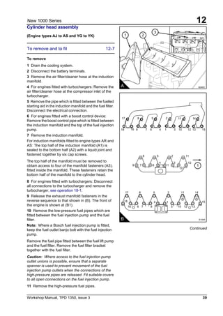
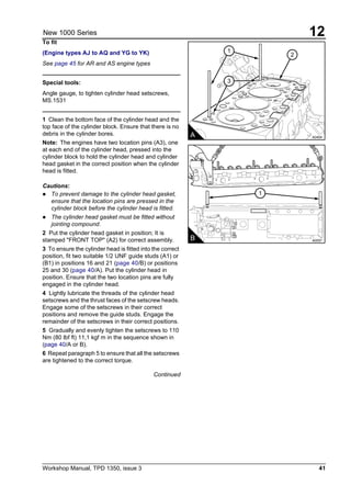
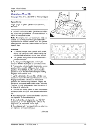
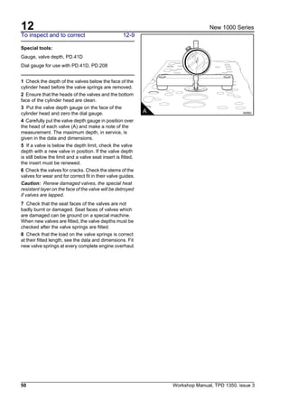
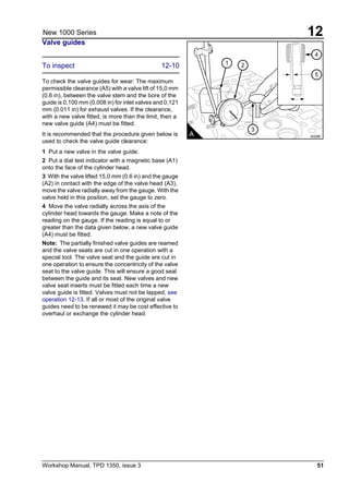
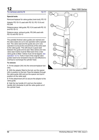
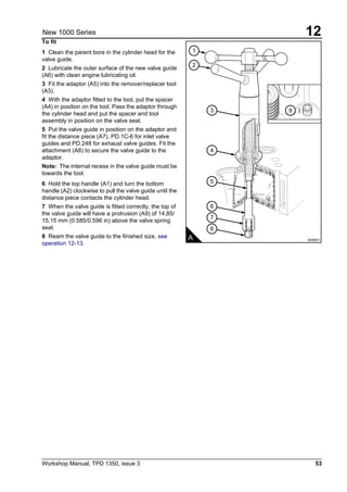
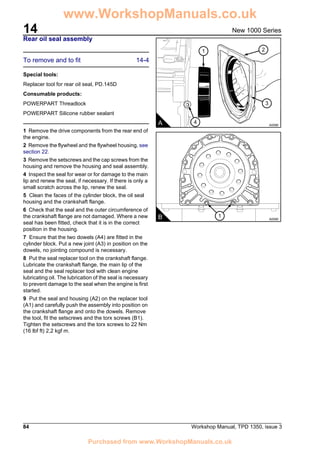
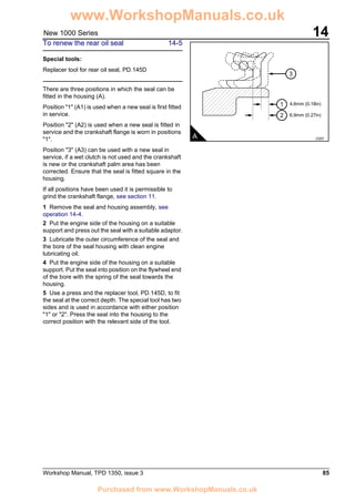
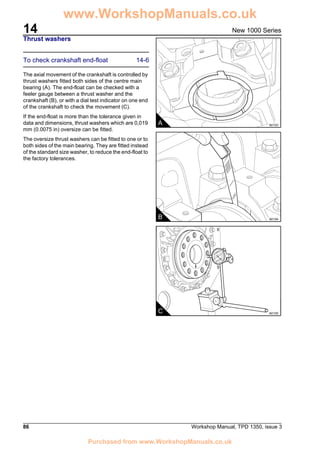
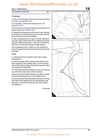
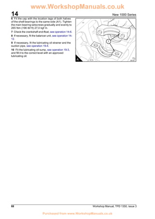
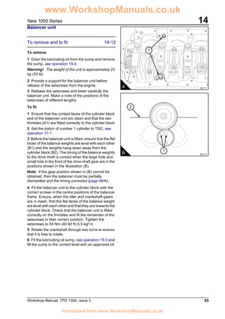
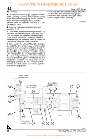
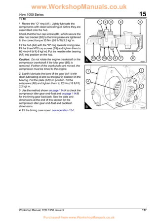
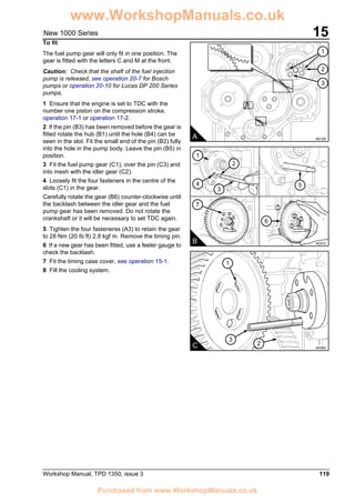
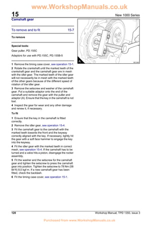
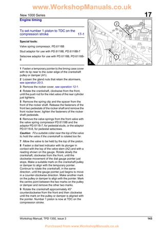
This document is a workshop manual providing instructions for repair and maintenance of Perkins 2800 Series diesel engines, including the 2806C-E18 TAG1 TAG2 and TAG3 models. It contains detailed specifications, repair and assembly procedures, torque specifications, and other technical information divided into chapters covering the cylinder head, pistons and connecting rods, crankshaft, timing gears, crankcase, and other engine systems. The manual is intended as a reference for technicians servicing these industrial diesel engines.
PERKINS 3000 SERIES 3012 CV12 12 CYLINDER DIESEL ENGINE Service Repair Manualjnekmsmme
This is the Highly Detailed factory service repair manual for thePERKINS 3000 SERIES 3012 CV12 12 CYLINDER DIESEL ENGINE, this Service Manual has detailed illustrations as well as step by step instructions,It is 100 percents complete and intact. they are specifically written for the do-it-yourself-er as well as the experienced mechanic.PERKINS 3000 SERIES 3012 CV12 12 CYLINDER DIESEL ENGINE Service Repair Workshop Manual provides step-by-step instructions based on the complete dis-assembly of the machine. It is this level of detail, along with hundreds of photos and illustrations, that guide the reader through each service and repair procedure. Complete download comes in pdf format which can work under all PC based windows operating system and Mac also, All pages are printable. Using this repair manual is an inexpensive way to keep your vehicle working properly.
Service Repair Manual Covers:
10 General information
11 Specifications
12 Cylinder head assembly
13 Pistons and connecting rods
14 Crankshaft assembly
15 Timing gears and timing case
16 Crankcase and cylinder liners
17 Camshafts and engine timing
18 Induction and exhaust system
19 Lubrication system
20 Fuel system
21 Cooling system
22 Flywheel and flywheel housing
23 Electrical equipment
24 Auxiliary equipment
25 Running-in and test
26 Special tools
User Handbook Cover:
1 General information
2 Engine views
3 Operation instructions
4 Preventive maintenance
5 Engine fluids
6 Fault diagnosis
7 Engine preservation
8 Parts and Service
9 Engine data
File Format: PDF
Compatible: All Versions of Windows & Mac
Language: English
Requirements: Adobe PDF Reader
NO waiting, Buy from responsible seller and get INSTANT DOWNLOAD, Without wasting your hard-owned money on uncertainty or surprise! All pages are is great to havePERKINS 3000 SERIES 3012 CV12 12 CYLINDER DIESEL ENGINE Service Repair Workshop Manual.
Looking for some other Service Repair Manual,please check:
https://www.aservicemanualpdf.com/
Thanks for visiting!
8
- The document is a technical and repair manual for N Series engines, split into multiple parts and sections.
- It provides specifications, torque values, disassembly/assembly instructions, and diagnosis procedures for mechanical and electrical/electronic components.
- Symbols are used to classify different types of information such as warnings, service operations, and environmental protection guidelines.
- General warnings include following safety procedures, using authorized tools, avoiding exposed moving parts, and handling hazardous materials carefully.
This is the Highly Detailed factory service repair manual for thePERKINS 1100 SERIES 1104D INDUSTRIAL ENGINE (MODEL NJ), this Service Manual has detailed illustrations as well as step by step instructions,It is 100 percents complete and intact. they are specifically written for the do-it-yourself-er as well as the experienced mechanic.PERKINS 1100 SERIES 1104D INDUSTRIAL ENGINE (MODEL NJ) Service Repair Workshop Manual provides step-by-step instructions based on the complete dis-assembly of the machine. It is this level of detail, along with hundreds of photos and illustrations, that guide the reader through each service and repair procedure. Complete download comes in pdf format which can work under all PC based windows operating system and Mac also, All pages are printable. Using this repair manual is an inexpensive way to keep your vehicle working properly.
Service Repair Manual Covers:
File Format: PDF
Compatible: All Versions of Windows & Mac
Language: English
Requirements: Adobe PDF Reader
NO waiting, Buy from responsible seller and get INSTANT DOWNLOAD, Without wasting your hard-owned money on uncertainty or surprise! All pages are is great to havePERKINS 1100 SERIES 1104D INDUSTRIAL ENGINE (MODEL NJ) Service Repair Workshop Manual.
Looking for some other Service Repair Manual,please check:
https://www.aservicemanualpdf.com/
Thanks for visiting!
8
This document contains a list of various electrical system components for a vehicle. It includes parts like the starter motor, batteries, alternator, fuses, relays, switches, and wiring diagrams. The list appears to describe the basic electrical circuits involved in starting the vehicle, running accessories, and charging the battery. Diagrams show the wiring connections between the battery, starter, ignition switch, and other core components.
This document provides operating instructions for Mercedes-Benz OM 904-926 LA BlueTec® diesel engines. It contains information on engine components, safety symbols, operating the engine safely and correctly, maintenance procedures, and technical specifications. The instructions emphasize using genuine Mercedes-Benz parts and servicing the engine at authorized workshops. BlueTec® engines require AdBlue® to meet emissions regulations, and operation without it can affect the engine warranty and vehicle approval.
PERKINS PHASER AND 1000 SERIES MODELS YD DIESEL ENGINE Service Repair Manualhfjskefmmmse
This is the Highly Detailed factory service repair manual for thePERKINS PHASER AND 1000 SERIES MODELS YD DIESEL ENGINE, this Service Manual has detailed illustrations as well as step by step instructions,It is 100 percents complete and intact. they are specifically written for the do-it-yourself-er as well as the experienced mechanic.PERKINS PHASER AND 1000 SERIES MODELS YD DIESEL ENGINE Service Repair Workshop Manual provides step-by-step instructions based on the complete dis-assembly of the machine. It is this level of detail, along with hundreds of photos and illustrations, that guide the reader through each service and repair procedure. Complete download comes in pdf format which can work under all PC based windows operating system and Mac also, All pages are printable. Using this repair manual is an inexpensive way to keep your vehicle working properly.
Service Repair Manual Covers:
File Format: PDF
Compatible: All Versions of Windows & Mac
Language: English
Requirements: Adobe PDF Reader
NO waiting, Buy from responsible seller and get INSTANT DOWNLOAD, Without wasting your hard-owned money on uncertainty or surprise! All pages are is great to havePERKINS PHASER AND 1000 SERIES MODELS YD DIESEL ENGINE Service Repair Workshop Manual.
Looking for some other Service Repair Manual,please check:
https://www.aservicemanualpdf.com/
Thanks for visiting!
The document discusses the benefits of exercise for mental health. Regular physical activity can help reduce anxiety and depression and improve mood and cognitive functioning. Exercise causes chemical changes in the brain that may help protect against mental illness and improve symptoms.
2002 yamaha sx viper 700 service repair manualjksmenmd
This document provides instructions and specifications for the periodic inspection, adjustment, and maintenance of various systems for a snowmobile, including the chassis, powertrain, engine, cooling system, carburetion, electrical, and specifications. It emphasizes the importance of thorough cleaning, using proper tools, keeping mated parts together, and following torque specifications for removal and reassembly. It provides details on machine identification numbers, recommended replacement parts and materials, and special tools needed for various maintenance tasks.
PERKINS 2200 SERIES 2206D-E13TA INDUSTRIAL ENGINE Service Repair Manualjsnekmse
This is the Highly Detailed factory service repair manual for thePERKINS 2200 SERIES 2206D-E13TA INDUSTRIAL ENGINE , this Service Manual has detailed illustrations as well as step by step instructions,It is 100 percents complete and intact. they are specifically written for the do-it-yourself-er as well as the experienced mechanic.PERKINS 2200 SERIES 2206D-E13TA INDUSTRIAL ENGINE Service Repair Workshop Manual provides step-by-step instructions based on the complete dis-assembly of the machine. It is this level of detail, along with hundreds of photos and illustrations, that guide the reader through each service and repair procedure. Complete download comes in pdf format which can work under all PC based windows operating system and Mac also, All pages are printable. Using this repair manual is an inexpensive way to keep your vehicle working properly.
Operation and Maintenance Manual Cover:
Safety Section
Product Information Section
Operation Section
Maintenance Section
Warranty Section
Index Section
Engine Schematic
Systems Operation Testing and Adjusting Cover:
Systems Operation Section
Testing and Adjusting Section
Fuel System
Air Inlet and Exhaust System
Lubrication System
Cooling System
Basic Engine
Electrical System
Index Section
Troubleshooting Manual Cover:
Introduction
Electronic System Overview
Configuration Parameters
Diagnostic Trouble Codes
Event Codes
Symptom Troubleshooting
Circuit Tests
Service
Index Section
File Format: PDF
Compatible: All Versions of Windows & Mac
Language: English
Requirements: Adobe PDF Reader
NO waiting, Buy from responsible seller and get INSTANT DOWNLOAD, Without wasting your hard-owned money on uncertainty or surprise! All pages are is great to havePERKINS 2200 SERIES 2206D-E13TA INDUSTRIAL ENGINE Service Repair Workshop Manual.
Looking for some other Service Repair Manual,please check:
https://www.aservicemanualpdf.com/
Thanks for visiting!
8
PERKINS 2800 SERIES 2806C-E18 TAG2 DIESEL ENGINE Service Repair Manualhjskemd seudkjmd
This is the Highly Detailed factory service repair manual for thePERKINS 2800 SERIES 2806C-E18 TAG2 DIESEL ENGINE, this Service Manual has detailed illustrations as well as step by step instructions,It is 100 percents complete and intact. they are specifically written for the do-it-yourself-er as well as the experienced mechanic.PERKINS 2800 SERIES 2806C-E18 TAG2 DIESEL ENGINE Service Repair Workshop Manual provides step-by-step instructions based on the complete dis-assembly of the machine. It is this level of detail, along with hundreds of photos and illustrations, that guide the reader through each service and repair procedure. Complete download comes in pdf format which can work under all PC based windows operating system and Mac also, All pages are printable. Using this repair manual is an inexpensive way to keep your vehicle working properly.
Service Repair Manual Covers:
1 General information
2 Specifications
3 Cylinder head assembly
4 Piston and connecting rod assemblies
5 Crankshaft assembly
6 Timing case and drive assembly
7 Cylinder block assembly
8 Engine timing
9 Aspiration system
10 Lubrication system
11 Fuel system
12 Cooling system
13 Flywheel and housing
14 Electrical equipment
15 Auxiliary equipment
16 Special tools
User Handbook Cover:
1 General information
2 Engine views
3 Operation instructions
4 Preventive maintenance
5 Engine fluids
6 Fault diagnosis
File Format: PDF
Compatible: All Versions of Windows & Mac
Language: English
Requirements: Adobe PDF Reader
NO waiting, Buy from responsible seller and get INSTANT DOWNLOAD, Without wasting your hard-owned money on uncertainty or surprise! All pages are is great to havePERKINS 2800 SERIES 2806C-E18 TAG2 DIESEL ENGINE Service Repair Workshop Manual.
Looking for some other Service Repair Manual,please check:
https://www.aservicemanualpdf.com/
Thanks for visiting!
8
PERKINS 1103 AND 1104 INDUSTRIAL ENGINE(Model DD)Service Repair Manualfusjjekkemmd
The document provides instructions for removing and installing fuel priming pumps and fuel filter bases on 1103 and 1104 Industrial engines. It describes two types of fuel priming pumps and two types of fuel filters. The removal procedure involves disconnecting fuel lines and electrical connectors, removing mounting screws, and draining any fuel. The installation procedure specifies cleaning components and reversing the removal steps, including reconnecting lines, installing screws, and priming the fuel system. Safety precautions are provided to prevent fluid spillage and the entry of contaminants.
Perkins 2500 series 2506 15 industrial engine ( mgd) service repair manualdfjjsekksekmsw
This document provides instructions for disassembling and assembling various components of an industrial engine. It begins with safety information, then lists the components and provides step-by-step instructions for removing, installing, and servicing each part. The components covered include the fuel system, turbocharger, cylinder head, camshaft, crankshaft, and other engine parts.
PERKINS 1300 SERIES WE DIESEL ENGINE Service Repair Manualhjskemd seudkjmd
This is the Highly Detailed factory service repair manual for thePERKINS 1300 SERIES WE DIESEL ENGINE, this Service Manual has detailed illustrations as well as step by step instructions,It is 100 percents complete and intact. they are specifically written for the do-it-yourself-er as well as the experienced mechanic.PERKINS 1300 SERIES WE DIESEL ENGINE Service Repair Workshop Manual provides step-by-step instructions based on the complete dis-assembly of the machine. It is this level of detail, along with hundreds of photos and illustrations, that guide the reader through each service and repair procedure. Complete download comes in pdf format which can work under all PC based windows operating system and Mac also, All pages are printable. Using this repair manual is an inexpensive way to keep your vehicle working properly.
Service Repair Manual Covers:
1 General information
2 Specifications
3 Cylinder head assembly
4 Piston and connecting rod assemblies
5 Crankshaft assembly
6 Timing case and drive assembly
7 Cylinder block assembly
8 Engine timing
9 Aspiration system
10 Lubrication system
11 Fuel system
12 Cooling system
13 Flywheel and housing
14 Electrical equipment
15 Auxiliary equipment
16 Special tools
User Handbook
1 General information
2 Engine views
3 Operation instructions
4 Preventive maintenance
5 Engine fluids
6 Fault diagnosis
File Format: PDF
Compatible: All Versions of Windows & Mac
Language: English
Requirements: Adobe PDF Reader
NO waiting, Buy from responsible seller and get INSTANT DOWNLOAD, Without wasting your hard-owned money on uncertainty or surprise! All pages are is great to havePERKINS 1300 SERIES WE DIESEL ENGINE Service Repair Workshop Manual.
Looking for some other Service Repair Manual,please check:
https://www.aservicemanualpdf.com/
Thanks for visiting!
8
This document outlines the steps needed to complete a home renovation project. It details hiring contractors to complete plumbing, electrical, and framing work before the installation of flooring, cabinets, fixtures, and interior and exterior finishes. Project management and scheduling tasks are also discussed to coordinate the phases of construction from start to finish.
Jcb isuzu 4 hk1 engine service repair manualdujjsjekkekmme
This document provides service information for Isuzu 4HK1 and 6HK1 diesel engines. It includes removal and installation instructions for various engine components as well as specifications and inspection guidelines. The document covers cylinder head, camshaft, crankshaft, pistons, connecting rods, valves, timing gears, turbocharger and other parts. Precautions are provided for each procedure.
New holland tl100 a tractor service repair manualuudjjjkskkmem
This document is a service manual for tractor models TL70A through TL100A. It contains sections on general guidelines, the engine, clutch, transmissions, and other systems. Each section provides specifications, views of components, troubleshooting information, and procedures for removal, installation, overhaul, and adjustment of parts.
This document is a workshop manual that provides removal, inspection, and installation instructions for various engine components of DD platform engines. It includes sections on the rocker cover, camshaft and related parts, cylinder head, pistons, crankshaft, lubrication system, cooling system, and other engine systems. The manual provides detailed step-by-step guidance on servicing these engine components.
Perkins 2500 series 2506 15 industrial engine (mga ) service repair manualjkmsedopl
The document provides an overview of the electronic control system for the 2506-15 industrial engine. It describes the main components of the system including the electronic control module, sensors, and injectors. It explains how the ECM uses signals from sensors to determine fuel injection timing and quantity to control engine speed and power output. It also discusses programmable parameters, passwords, and troubleshooting diagnostic codes.
The document provides troubleshooting information for the 2506-15 industrial engine. It discusses important safety information and outlines the electronic control system. The electronic system uses an electronic control module and electronic unit injectors. The ECM controls fuel injection and timing based on sensor inputs. Programmable parameters can be changed using a service tool. Diagnostic codes and event codes are used to help troubleshoot issues. Functional tests are provided to test components and circuits.
Audi A5 coupe 2008 Trabajos de montaje interiores.pdfjcarrey
Este documento es el manual de reparaciones para el Audi A5 Coupé de 2008. Contiene instrucciones detalladas para desmontar y montar varias partes del interior del vehículo como la guantera, la consola central, los reposabrazos y el espejo retrovisor interior. El manual también incluye información sobre los cinturones de seguridad y su instalación correcta.
This document is a workshop manual for Sisudiesel 320, 420, 620, and 634 diesel engines. It provides specifications, construction details, maintenance instructions, and safety information for working on these engine types. The manual covers topics such as cylinder block components, cylinder head removal, valve maintenance, flywheel housing, lubrication system, cooling system, and more. Safety precautions are listed and technicians are instructed to follow the provided torque specifications for proper repair and installation of engine parts.
Liebherr R 944 C Hydraulic Excavator Service Repair Manual SN:16469 and upjknsmekmd
This is the Highly Detailed factory service repair manual for theLIEBHERR R 944 C HYDRAULIC EXCAVATOR, this Service Manual has detailed illustrations as well as step by step instructions,It is 100 percents complete and intact. they are specifically written for the do-it-yourself-er as well as the experienced mechanic.LIEBHERR R 944 C HYDRAULIC EXCAVATOR Service Repair Workshop Manual provides step-by-step instructions based on the complete dis-assembly of the machine. It is this level of detail, along with hundreds of photos and illustrations, that guide the reader through each service and repair procedure. Complete download comes in pdf format which can work under all PC based windows operating system and Mac also, All pages are printable. Using this repair manual is an inexpensive way to keep your vehicle working properly.
Service Repair Manual Covers:
General Information
Tools
Technical Data / Maintenance Guidelines
Engine
Coupling / Splitterbox
Hydraulic System
Hydraulic Components
Electrical System
Swing Gear
Swing Ring
Travel Gear
Track Components
Special Attachments / Additional Installations
Cab / Heater / Air Conditioning System
Central Lubrication
File Format: PDF
Compatible: All Versions of Windows & Mac
Language: English
Requirements: Adobe PDF Reader
NO waiting, Buy from responsible seller and get INSTANT DOWNLOAD, Without wasting your hard-owned money on uncertainty or surprise! All pages are is great to haveLIEBHERR R 944 C HYDRAULIC EXCAVATOR Service Repair Workshop Manual.
Looking for some other Service Repair Manual,please check:
https://www.aservicemanualpdf.com/
Thanks for visiting!
8
Este documento proporciona información sobre el sistema eléctrico de un vehículo. Incluye esquemas de circuitos y descripciones de componentes como faros, luces exteriores, testigos ópticos, limpiaparabrisas y más. Explica cómo interpretar los diagramas y realizar pruebas y reparaciones de varios sistemas eléctricos y electrónicos del vehículo.
PERKINS 1300 SERIES WF DIESEL ENGINE Service Repair Manualhjnskmdje
This is the Highly Detailed factory service repair manual for thePERKINS 1300 SERIES WF DIESEL ENGINE, this Service Manual has detailed illustrations as well as step by step instructions,It is 100 percents complete and intact. they are specifically written for the do-it-yourself-er as well as the experienced mechanic.PERKINS 1300 SERIES WF DIESEL ENGINE Service Repair Workshop Manual provides step-by-step instructions based on the complete dis-assembly of the machine. It is this level of detail, along with hundreds of photos and illustrations, that guide the reader through each service and repair procedure. Complete download comes in pdf format which can work under all PC based windows operating system and Mac also, All pages are printable. Using this repair manual is an inexpensive way to keep your vehicle working properly.
Service Repair Manual Covers:
1 General information
2 Specifications
3 Cylinder head assembly
4 Piston and connecting rod assemblies
5 Crankshaft assembly
6 Timing case and drive assembly
7 Cylinder block assembly
8 Engine timing
9 Aspiration system
10 Lubrication system
11 Fuel system
12 Cooling system
13 Flywheel and housing
14 Electrical equipment
15 Auxiliary equipment
16 Special tools
User Handbook
1 General information
2 Engine views
3 Operation instructions
4 Preventive maintenance
5 Engine fluids
6 Fault diagnosis
File Format: PDF
Compatible: All Versions of Windows & Mac
Language: English
Requirements: Adobe PDF Reader
NO waiting, Buy from responsible seller and get INSTANT DOWNLOAD, Without wasting your hard-owned money on uncertainty or surprise! All pages are is great to havePERKINS 1300 SERIES WF DIESEL ENGINE Service Repair Workshop Manual.
Looking for some other Service Repair Manual,please check:
https://www.aservicemanualpdf.com/
Thanks for visiting!
8
New holland tm155 tractor service repair manualusuejjskkemme
This document is a repair manual that provides instructions for servicing TM120, TM130, TM140, TM155, TM175, and TM190 tractors. It contains sections covering the general information, engine, clutch, transmission, drivelines, front and rear axles, brakes, hydraulics, steering, electrical systems, and cab. Safety precautions and maintenance instructions are provided throughout. The manual is intended solely for use by authorized service technicians according to the specific guidelines and procedures outlined.
Jcb diesel 1000 series engine model yg service repair manualfjskeksmemedc
This document is a workshop manual for Perkins New 1000 Series diesel engines used in industrial and agricultural applications. It provides detailed instructions for maintenance, repair, and overhaul of engine components. The manual contains 25 chapters covering general information, specifications, and repair/overhaul procedures for all major engine systems.
Jcb diesel 1000 series engine model aj service repair manualfujdjjjskekeme
This document is a workshop manual for Perkins New 1000 Series diesel engines used in industrial and agricultural applications. It provides detailed instructions on servicing and repairing engine components such as the cylinder head, pistons, crankshaft, timing case, cylinder block, and other systems. The manual contains chapters covering general information, specifications, disassembly and assembly procedures, inspection criteria, and specifications/dimensions for components. It is intended to guide mechanics in properly servicing and repairing these engines.
Jcb diesel 1000 series engine model ak service repair manualfjeisldkmemm
This document is a workshop manual for Perkins New 1000 Series diesel engines used in industrial and agricultural applications. It provides detailed instructions on servicing and repairing engine components like the cylinder head, pistons, crankshaft, timing case, cylinder block, and other systems. The manual contains chapters covering general information, specifications, repair procedures, and dimensions for the different engine parts. It is intended to guide mechanics in properly servicing and overhauling the 1000 Series engines.
Jcb diesel 1000 series engine model yg service repair manualfujdjfjjskekmm
This document is a workshop manual for Perkins New 1000 Series diesel engines used in industrial and agricultural applications. It provides detailed instructions for maintenance, repair, and overhaul of engine components. The manual contains 25 chapters covering general information, specifications, and repair/overhaul procedures for all major engine systems.
Jcb diesel 1000 series engine model ar service repair manualfujdjffjjskkemem
This document is a workshop manual for Perkins New 1000 Series diesel engines used in industrial and agricultural applications. It provides detailed instructions on servicing and repairing engine components like the cylinder head, pistons, crankshaft, timing case, cylinder block, and other systems. The manual contains chapters covering general information, specifications, repair procedures, and dimensions for the different engine parts. It is intended to guide mechanics in properly servicing and overhauling the 1000 Series engines.
Jcb diesel 1000 series engine model yh service repair manualfjsekksmefm
This document is a workshop manual for Perkins New 1000 Series diesel engines used in industrial and agricultural applications. It provides detailed instructions on servicing and repairing engine components like the cylinder head, pistons, crankshaft, timing case, cylinder block, and other systems. The manual contains chapters covering general information, specifications, repair procedures, and dimensions for the different engine parts. It is intended to guide mechanics in properly servicing and overhauling the 1000 Series engines.
Jcb diesel 1000 series engine model am service repair manualfusjfjskefksmem
This document is a workshop manual for Perkins New 1000 Series diesel engines used in industrial and agricultural applications. It provides detailed instructions for maintenance, repair, and overhaul of engine components. The manual contains 25 chapters covering general information, specifications, and repair/overhaul procedures for all major engine systems.
Jcb diesel 1000 series engine model aq service repair manualfjjsfkskemem
This document is a workshop manual for Perkins New 1000 Series diesel engines used in industrial and agricultural applications. It provides detailed instructions for maintenance, repair, and overhaul of engine components. The manual contains 25 chapters covering general information, specifications, and repair/overhaul procedures for all major engine systems.
Jcb diesel 1000 series engine model ak service repair manualfusjkkskemmf
This document is a workshop manual for Perkins New 1000 Series diesel engines used in industrial and agricultural applications. It provides detailed instructions for maintenance, repair, and overhaul of engine components. The manual contains 25 chapters covering general information, specifications, and repair/overhaul procedures for all major engine systems.
Jcb diesel 1000 series engine model yk service repair manualufjjjdfjkksekmme
This document is a workshop manual for Perkins New 1000 Series diesel engines used in industrial and agricultural applications. It provides detailed instructions for maintenance, repair, and overhaul of engine components. The manual contains 25 chapters covering general information, specifications, and repair/overhaul procedures for all major engine systems.
Jcb diesel 1000 series engine model am service repair manualfjskekmmem
This document is a workshop manual for Perkins New 1000 Series diesel engines used in industrial and agricultural applications. It provides detailed instructions for maintenance, repair, and overhaul of engine components. The manual contains 25 chapters covering general information, specifications, and repair/overhaul procedures for all major engine systems.
Jcb diesel 1000 series engine model aq service repair manualufujjdfjjskekemm
This document is a workshop manual for Perkins New 1000 Series diesel engines used in industrial and agricultural applications. It provides detailed instructions for maintenance, repair, and overhaul of engine components. The manual contains 25 chapters covering general information, specifications, and repair/overhaul procedures for all major engine systems.
Jcb diesel 1000 series engine model yh service repair manualfujdfjjkswkemem
This document is a workshop manual for Perkins New 1000 Series diesel engines used in industrial and agricultural applications. It provides detailed instructions for maintenance, repair, and overhaul of engine components. The manual contains 25 chapters covering general information, specifications, and repair/overhaul procedures for all major engine systems.
Jcb diesel 1000 series engine model ak service repair manualufjdjfjkskekemm
This document is a workshop manual for Perkins New 1000 Series diesel engines used in industrial and agricultural applications. It provides detailed instructions for maintenance, repair, and overhaul of engine components. The manual contains 25 chapters covering general information, specifications, and repair/overhaul procedures for all major engine systems.
Jcb diesel 1000 series engine model as service repair manualfujjdjjkskemme
This document is a workshop manual for Perkins New 1000 Series diesel engines used in industrial and agricultural applications. It provides detailed instructions for maintenance, repair, and overhaul of engine components. The manual contains 25 chapters covering general information, specifications, and repair/overhaul procedures for all major engine systems.
Jcb diesel 1000 series engine model am service repair manualufjdjfjkskefmme
This document is a workshop manual for Perkins New 1000 Series diesel engines used in industrial and agricultural applications. It provides detailed instructions for maintenance, repair, and overhaul of engine components. The manual contains 25 chapters covering general information, specifications, and repair/overhaul procedures for all major engine systems.
Jcb diesel 1000 series engine model aq service repair manualfjskekqazdmmem
This document is a workshop manual for Perkins New 1000 Series diesel engines used in industrial and agricultural applications. It provides detailed instructions on servicing and repairing engine components like the cylinder head, pistons, crankshaft, timing case, cylinder block, and other systems. The manual contains chapters covering general information, specifications, repair procedures, and dimensions for the different engine parts. It is intended to guide mechanics in properly servicing and repairing these engines.
Jcb diesel 1000 series engine model ap service repair manualfujsjefjkskeksmem
This document is a workshop manual for Perkins New 1000 Series diesel engines used in industrial and agricultural applications. It provides detailed instructions on servicing and repairing engine components like the cylinder head, pistons, crankshaft, timing case, cylinder block, and other systems. The manual contains chapters covering general information, specifications, repair procedures, and dimensions for the different engine parts. It is intended to guide mechanics in properly servicing and overhauling the 1000 Series engines.
Jcb diesel 1000 series engine model yg service repair manualfujsjefjkskekfm
This document is a workshop manual for Perkins New 1000 Series diesel engines used in industrial and agricultural applications. It provides detailed instructions on servicing and repairing engine components like the cylinder head, pistons, crankshaft, timing case, cylinder block, and other systems. The manual contains chapters covering general information, specifications, repair procedures, and dimensions for the different engine parts. It is intended to guide mechanics in properly servicing and overhauling the 1000 Series engines.
Jcb diesel 1000 series engine model ap service repair manualufjjdjjkskemme
This document is a workshop manual for Perkins New 1000 Series diesel engines used in industrial and agricultural applications. It provides detailed instructions for maintenance, repair, and overhaul of engine components. The manual contains 25 chapters covering general information, specifications, and repair/overhaul procedures for all major engine systems.
Similar to Perkins new 1000 series workshop manual!!! (20)
Welcome to ASP Cranes, your trusted partner for crane solutions in Raipur, Chhattisgarh! With years of experience and a commitment to excellence, we offer a comprehensive range of crane services tailored to meet your lifting and material handling needs.
At ASP Cranes, we understand the importance of reliable and efficient crane operations in various industries, from construction and manufacturing to logistics and infrastructure development. That's why we strive to deliver top-notch solutions that enhance productivity, safety, and cost-effectiveness for our clients.
Our services include:
Crane Rental: Whether you need a crawler crane for heavy lifting or a hydraulic crane for versatile operations, we have a diverse fleet of well-maintained cranes available for rent. Our rental options are flexible and can be customized to suit your project requirements.
Crane Sales: Looking to invest in a crane for your business? We offer a wide selection of new and used cranes from leading manufacturers, ensuring you find the perfect equipment to match your needs and budget.
Crane Maintenance and Repair: To ensure optimal performance and safety, regular maintenance and timely repairs are essential for cranes. Our team of skilled technicians provides comprehensive maintenance and repair services to keep your equipment running smoothly and minimize downtime.
Crane Operator Training: Proper training is crucial for safe and efficient crane operation. We offer specialized training programs conducted by certified instructors to equip operators with the skills and knowledge they need to handle cranes effectively.
Custom Solutions: We understand that every project is unique, which is why we offer custom crane solutions tailored to your specific requirements. Whether you need modifications, attachments, or specialized equipment, we can design and implement solutions that meet your needs.
At ASP Cranes, customer satisfaction is our top priority. We are dedicated to delivering reliable, cost-effective, and innovative crane solutions that exceed expectations. Contact us today to learn more about our services and how we can support your project in Raipur, Chhattisgarh, and beyond. Let ASP Cranes be your trusted partner for all your crane needs!
EV Charging at MFH Properties by Whitaker JamiesonForth
Whitaker Jamieson, Senior Specialist at Forth, gave this presentation at the Forth Addressing The Challenges of Charging at Multi-Family Housing webinar on June 11, 2024.
Implementing ELDs or Electronic Logging Devices is slowly but surely becoming the norm in fleet management. Why? Well, integrating ELDs and associated connected vehicle solutions like fleet tracking devices lets businesses and their in-house fleet managers reap several benefits. Check out the post below to learn more.
Charging Fueling & Infrastructure (CFI) Program Resources by Cat PleinForth
Cat Plein, Development & Communications Director of Forth, gave this presentation at the Forth and Electrification Coalition CFI Grant Program - Overview and Technical Assistance webinar on June 12, 2024.
Charging Fueling & Infrastructure (CFI) Program by Kevin MillerForth
Kevin Miller, Senior Advisor, Business Models of the Joint Office of Energy and Transportation gave this presentation at the Forth and Electrification Coalition CFI Grant Program - Overview and Technical Assistance webinar on June 12, 2024.
Understanding Catalytic Converter Theft:
What is a Catalytic Converter?: Learn about the function of catalytic converters in vehicles and why they are targeted by thieves.
Why are They Stolen?: Discover the valuable metals inside catalytic converters (such as platinum, palladium, and rhodium) that make them attractive to criminals.
Steps to Prevent Catalytic Converter Theft:
Parking Strategies: Tips on where and how to park your vehicle to reduce the risk of theft, such as parking in well-lit areas or secure garages.
Protective Devices: Overview of various anti-theft devices available, including catalytic converter locks, shields, and alarms.
Etching and Marking: The benefits of etching your vehicle’s VIN on the catalytic converter or using a catalytic converter marking kit to make it traceable and less appealing to thieves.
Surveillance and Monitoring: Recommendations for using security cameras and motion-sensor lights to deter thieves.
Statistics and Insights:
Theft Rates by Borough: Analysis of data to determine which borough in NYC experiences the highest rate of catalytic converter thefts.
Recent Trends: Current trends and patterns in catalytic converter thefts to help you stay aware of emerging hotspots and tactics used by thieves.
Benefits of This Presentation:
Awareness: Increase your awareness about catalytic converter theft and its impact on vehicle owners.
Practical Tips: Gain actionable insights and tips to effectively prevent catalytic converter theft.
Local Insights: Understand the specific risks in different NYC boroughs, helping you take targeted preventive measures.
This presentation aims to equip you with the knowledge and tools needed to protect your vehicle from catalytic converter theft, ensuring you are prepared and proactive in safeguarding your property.
Expanding Access to Affordable At-Home EV Charging by Vanessa WarheitForth
Vanessa Warheit, Co-Founder of EV Charging for All, gave this presentation at the Forth Addressing The Challenges of Charging at Multi-Family Housing webinar on June 11, 2024.
Charging and Fueling Infrastructure Grant: Round 2 by Brandt HertensteinForth
Brandt Hertenstein, Program Manager of the Electrification Coalition gave this presentation at the Forth and Electrification Coalition CFI Grant Program - Overview and Technical Assistance webinar on June 12, 2024.
2. 2 Workshop Manual, TPD 1350, issue 3
New 1000 Series
Chapters
10 General information
11 Specifications
12 Cylinder head assembly
13 Piston and connecting rod assemblies
14 Crankshaft assembly
15 Timing case and drive assembly
16 Cylinder block assembly
17 Engine timing
18 Aspiration system
19 Lubrication system
20 Fuel system
21 Cooling system
22 Flywheel and housing
23 Electrical equipment
24 Auxiliary equipment
25 Special tools
The following pages contain a detailed table of contents.
Perkins Approved Clear English
This publication is written in
14. 14 Workshop Manual, TPD 1350, issue 3
New 1000 Series
24 Auxiliary equipment
Compressors
General description ... ... ... ... ... ... ... ... ... ... ... ... ... ... ... ... ... ... ... ... ... ... ... ... ... .. 275
Operation... ... ... ... ... .... ... ... ... ... ... ... ... ... ... ... ... ... ... ... ... ... ... ... ... ... ... ... ... .. 275
Bendix Compressors
24-1 To remove and to fit ... ... ... ... ... ... ... ... ... ... ... ... ... ... ... ... ... ... ... ... ... ... ... .. 276
Data and dimensions ... ... ... ... ... ... ... ... ... ... ... ... ... ... ... ... ... ... ... ... ... ... ... ... .. 279
Power steering pump
24-2 To remove and to fit ... ... ... ... ... ... ... ... ... ... ... ... ... ... ... ... ... ... ... ... ... ... ... .. 280
Adaptor for a hydraulic pump or a steering pump with a splined drive
24-3 To remove and to fit ... ... ... ... ... ... ... ... ... ... ... ... ... ... ... ... ... ... ... ... ... ... ... .. 281
24-4 To dismantle and to assemble ... ... ... ... ... ... ... ... ... ... ... ... ... ... ... ... ... ... ... .. 281
Exhauster
24-5 To remove and to fit ... ... ... ... ... ... ... ... ... ... ... ... ... ... ... ... ... ... ... ... ... ... ... .. 283
25 Special tools
List of special tools ... ... ... ... ... ... ... ... ... ... ... ... ... ... ... ... ... ... ... ... ... ... ... ... ... .. 286
15. Workshop Manual, TPD 1350, issue 3 15
10
New 1000 Series
General information 10
Introduction
This workshop manual has been written to provide
assistance in the service and overhaul of Perkins New
1000 Series engines. For overhaul procedures the
assumption is made that the engine is removed from
the application. The engine conforms with USA (EPA/
CARB) stage 1 and EEC stage 1 emissions legislation
for agricultural and industrial applications.
Most of the general information which is included
in the relevant User's Handbook (sections 1 to 9)
has not been repeated in this workshop manual
and the two publications should be used together.
Where the information applies only to certain engine
types, this is indicated in the text.
The details of some operations will be different
according to the of fuel injection pump which is fitted.
The specific pump type used can be found by
reference to the manufacturer's identification plate on
the pump body. Generally, the type of pump fitted is
as shown below.
Lucas DP200 Series
Bosch EPVE
Stanadyne DB4
When reference is made to the "left" or "right" side of
the engine, this is as seen from the flywheel end of the
engine.
Special tools have been made available and a list of
these is given in section 25. Reference to the relevant
special tools is also made at the beginning of each
operation, where relevant.
POWERPART recommended consumable products
are listed on page 21. Reference to the relevant
consumable products is also made at the beginning of
each operation, where relevant.
Data and dimensions are included at the end of each
section.
Read and remember the "Safety precautions".
They are given for your protection and must be
used at all times.
Danger is indicated in the text by two methods:
Warning! This indicates that there is a possible
danger to the person.
Caution: This indicates that there is a possible
danger to the engine.
Note: Is used where the information is important, but
there is not a danger.
17. Workshop Manual, TPD 1350, issue 3 17
10New 1000 Series
Engine identification
The Perkins New 1000 Series engines have been
designed for industrial and agricultural applications.
There are both four and six cylinder engines, each of
which will have three basic engine types, naturally
aspirated, turbocharged and turbocharged with an
intercooler.
In this workshop manual, the different engine types
are indicated by their code letters. These are the first
two letters of the engine number as indicated below:
Code letters Engine type
AJ Four cylinder, naturally
aspirated.
AK Four cylinder, turbocharged.
AM Four cylinder, turbocharged
and intercooled.
AP Four cylinder, naturally
aspirated, belt driven coolant
pump.
AQ Four cylinder, turbocharged,
belt driven coolant pump.
AR Four cylinder, naturally
aspirated, 103 mm cylinder
bore.
AS Four cylinder, naturally
aspirated, belt driven coolant
pump, 103 mm cylinder bore.
YG Six cylinder, naturally
aspirated.
YH Six cylinder, turbocharged.
YK Six cylinder, turbocharged and
intercooled.
The correct identification of the engine is by the full
engine number.
The engine number is stamped on a label which is
fastened to the left side (A2) of the cylinder block. An
example of an engine number is:
AK80920*U510256B*
If you need parts, service or information for your
engine, you must give the complete engine number to
your Perkins distributor. If there is a number in the
area of the label marked TPL No
, then this number
must also be given to your Perkins distributor.
Other identification labels fitted to the engine include:
An emissions legislation label (A3) fitted to the side of
the cylinder block.
A label (A1) with the fuel injection pump part numbers.
If a short engine has been fitted in service two engine
serial numbers and a TPL number are stamped on the
engine serial number pad (B3):
Examples of the serial numbers are shown in (B).
If parts for the short engine are needed in service, use
the serial number (B4). If parts which were moved
from the original engine to the short engine are
needed, use the serial number (B1) and the TPL
number (B2).
21
3
A A0043
4
1
2
3
B A0045
AK80920*U510256B*
AJ39770 TPL No 212
18. 10
18 Workshop Manual, TPD 1350, issue 3
New 1000 Series
General safety precautions
These safety precautions are important. You must
refer also to the local regulations in the country of use.
Some items only refer to specific applications.
! Only use these engines in the type of application
for which they have been designed.
! Do not change the specification of the engine.
! Do not smoke when you put fuel in the tank.
! Clean away fuel which has been spilt. Material
which has been contaminated by fuel must be
moved to a safe place.
! Do not put fuel in the tank while the engine runs
(unless it is absolutely necessary).
! Do not clean, add lubricating oil, or adjust the
engine while it runs (unless you have had the
correct training; even then extreme care must be
used to prevent injury).
! Do not make adjustments that you do not
understand.
! Ensure that the engine does not run in a location
where it can cause a concentration of toxic
emissions.
! Other persons must be kept at a safe distance
while the engine or auxiliary equipment is in
operation.
! Do not permit loose clothing or long hair near
moving parts.
! Keep away from moving parts during engine
operation. Warning! Some moving parts cannot
be seen clearly while the engine runs.
! Do not operate the engine if a safety guard has
been removed.
! Do not remove the filler cap or any component of
the cooling system while the engine is hot and
while the coolant is under pressure, because
dangerous hot coolant can be discharged.
! Do not use salt water or any other coolant which
can cause corrosion in the closed circuit of the
cooling system.
! Do not allow sparks or fire near the batteries
(especially when the batteries are on charge)
because the gases from the electrolyte are highly
flammable. The battery fluid is dangerous to the
skin and especially to the eyes.
! Disconnect the battery terminals before a repair is
made to the electrical system.
! Only one person must control the engine.
! Ensure that the engine is operated only from the
control panel or from the operators position.
! If your skin comes into contact with high-pressure
fuel, obtain medical assistance immediately.
! Diesel fuel and lubricating oil (especially used
lubricating oil) can damage the skin of certain
persons. Protect your hands with gloves or a
special solution to protect the skin.
! Do not wear clothing which is contaminated by
lubricating oil. Do not put material which is
contaminated with oil into the pockets of clothing.
! Discard used lubricating oil in a safe place to
prevent contamination.
! Ensure that the control lever of the transmission
drive is in the "out-of-drive" position before the
engine is started.
! Use extreme care if emergency repairs must be
made in adverse conditions.
! The combustible material of some components of
the engine (for example certain seals) can
become extremely dangerous if it is burned. Never
allow this burnt material to come into contact with
the skin or with the eyes, see page 20.
! Read and use the instructions relevant to lift
equipment which are given on page 19.
! Always use a safety cage to protect the operator
when a component is to be pressure tested in a
container of water. Fit safety wires to secure the
plugs which seal the hose connections of a
component which is to be pressure tested.
! Do not allow compressed air to contact your skin.
If compressed air enters your skin, obtain medical
help immediately.
! Turbochargers operate at high speed and at high
temperatures. Keep fingers, tools and items away
from the inlet and outlet ports of the turbocharger
and prevent contact with hot surfaces.
! Do not clean an engine while it runs. If cold
cleaning fluids are applied to a hot engine, certain
components on the engine may be damaged.
! Fit only genuine Perkins parts.
19. Workshop Manual, TPD 1350, issue 3 19
10New 1000 Series
Engine lift equipment
The maximum weight of the engine without coolant,
lubricant or a gearbox fitted will vary for different
applications. It is recommended that lift equipment of
the minimum capacity listed below is used:
Four cylinder engines . . . . . . . . . . 500 kg (1100 lbs)
Six cylinder engines. . . . . . . . . . . . 600 kg (1320 lbs)
Before the engine is lifted:
! Always use lift equipment of the approved type
and of the correct capacity to lift the engine. It is
recommended that lift equipment of the type
shown in (A) is used, to provide a vertical lift
directly above the engine lift brackets (A1). Never
use a single lift bracket to raise an engine.
! Check the engine lift brackets for damage and that
they are secure before the engine is lifted. The
torque for the setscrews for the engine lift brackets
is 44 Nm (33 lbf ft) 4,5 kgf m.
! To prevent damage to the rocker cover, ensure
that there is clearance between the hooks and the
rocker cover.
! Use lift equipment or obtain assistance to lift
heavy engine components such as the cylinder
block, cylinder head, balancer unit, flywheel
housing, crankshaft and flywheel.
.
A A0044
1
20. 10
20 Workshop Manual, TPD 1350, issue 3
New 1000 Series
Viton seals
Some seals used in engines and in components fitted
to engines are made of Viton.
Viton is used by many manufacturers and is a safe
material under normal conditions of operation.
If Viton is burned, a product of this burnt material is an
acid which is extremely dangerous. Never allow this
burnt material to come into contact with the skin or
with the eyes.
If it is necessary to come into contact with
components which have been burnt, ensure that the
precautions which follow are used:
! Ensure that the components have cooled.
! Use neoprene gloves and discard the gloves
safely after use.
! Wash the area with calcium hydroxide solution
and then with clean water.
! Disposal of components and gloves which are
contaminated must be in accordance with local
regulations.
If there is contamination of the skin or eyes, wash the
affected area with a continuous supply of clean water
or with calcium hydroxide solution for 15-60 minutes.
Obtain immediate medical attention.
.
21. Workshop Manual, TPD 1350, issue 3 21
10New 1000 Series
POWERPART recommended
consumable products
Perkins have made available the products
recommended below in order to assist in the correct
operation, service and maintenance of your engine
and your machine. The instructions for the use of
each product are given on the outside of each
container. These products are available from your
Perkins distributor.
POWERPART Antifreeze
Protects the cooling system against frost and
corrosion. Part number 1 litre 21825166 or 5 litres
21825167, refer to the User's Handbook.
POWERPART Easy Flush
Cleans the cooling system. Part number 2182501
POWERPART Jointing compound
Universal jointing compound which seals joints.
Currently Hylomar. Part number 1861155 or
1861117.
POWERPART Silicone rubber sealant
Silicone rubber sealant which prevents leakage
through gaps.Currently Hylosil. Part number
1861108.
POWERPART Lay-Up 1
A diesel fuel additive for protection against corrosion.
Part number 1772204, refer to the User's Handbook.
POWERPART Lay-Up 2
Protects the inside of the engine and of other closed
systems. Part number 1762811, refer to the User's
Handbook.
POWERPART Lay-Up 3
Protects outside metal parts. Part number 1734115,
refer to the User's Handbook.
POWERPART Chisel
Allows easy removal of old gaskets and joints.
Currently Loctite chisel. Part number 21825163.
POWERPART Repel
Dries damp equipment and gives protection against
corrosion. Passes through dirt and corrosion to
lubricate and to assist removal of components.
Currently Loctite repel. Part number 21825164.
POWERPART Threadlock
To retain small fasteners where easy removal is
necessary. Currently Loctite 222e. Part number
21820222.
POWERPART Studlock
To permanently retain large fasteners and studs.
Currently Loctite 270. Part number 21820270.
POWERPART Nutlock
To retain and seal threaded fasteners and cup plugs
where easy removal is necessary. Currently Loctite
242e. Part number 21820242
POWERPART Liquid gasket
To seal flat faces of components where no joint is
used. Especially suitable for aluminium components.
Currently Loctite 518. Part number 21820518
POWERPART Threadlock (hydraulic/pnuematic)
To retain and seal pipe connections with fine threads.
Especially suitable for hydraulic and pneumatic
systems. Currently Loctite 542. Part number
21820542
POWERPART Threadlock (pipe)
To retain and seal pipe connections with coarse
threads. Pressure systems can be used immediately.
Currently Loctite 575. Part number 21820575.
POWERPART Retainer (oil tolerant)
To retain components which have a transition fit.
Currently Loctite 603. Part number 21820603.
POWERPART Retainer (high strength)
To retain components which have an interference fit.
Currently Loctite 638. Part number 21820638.
POWERPART Atomiser thread sealant
To seal the threads of the atomiser into the cylinder
head. Currently Hylomar Advance Formulation. Part
number 21825474.
Continued
22. 10
22 Workshop Manual, TPD 1350, issue 3
New 1000 Series
POWERPART Compound
To seal the outer diameter of seals. Currently Loctite
Forma Gasket No 2. Part number 1861147.
POWERPART Platelock
For tight fitted metal surfaces. Suitable for metal
plated surfaces and stainless steel, Currently Loctite
243. Part number 21826039.
POWERPART Gasket eliminator
Improves flange sealing when a gasket is not used. It
provides a seal with temperature resistance that is
flexible in positions where vibration and pressure
occur. Currently Loctite 515. Part number 21826040.
POWERPART Silicone adhesive
An RTV silicone adhesive for application where low-
pressure tests occur before the adhesive sets. Used
to prevent leakage where movement of the joint
occurs. Currently Loctite 5900. Part number
21826038.
24. 11
24 Workshop Manual, TPD 1350, issue 3
New 1000 Series
Thread sealant
When setscrews or studs are fitted into holes which
are tapped through the cylinder block, a suitable
sealant must be used to prevent leakage.
Micro encapsulated anaerobic sealant (M.E.A.S)
fasteners have been introduced instead of jointing
compounds or other sealants when the fasteners are
fitted in through holes into oil or coolant passages.
The identification of these fasteners, as supplied, is
by a red, blue, or other colour sealant around the
fastener threads.
With M.E.A.S. sealed studs, the sealed end must be
fitted into the cylinder head / cylinder block etc.
Ensure that the threaded holes have a 1,59 mm
(0.0625 in) 45° chamfer, to ensure that when the new
fasteners are fitted the M.E.A.S. sealant is not
removed. If the fasteners have to be removed and
fitted again, the threads must be cleaned and a
suitable sealant used.
25. Workshop Manual, TPD 1350, issue 3 25
11New 1000 Series
Standard torque tensions
Most of the torque tensions on the engine are standard. Special torque tensions are listed in the separate
special torque tables. The standard torque tensions listed in the tables below can be used when a special
torque is not necessary.
The torque tensions below apply to components lubricated lightly with clean engine oil before they are fitted.
Standard torques for setscrews and nuts
Standard torques for studs (metal end)
Standard torques for pipe unions, plugs, and adaptors
Torque
Thread Size Nm lbf ft kgf m
M6 x 1,00
M8 x 1,25
M10 x 1,50
M12 x 1,75
M14 x 2,00
M16 x 2,00
9
22
44
78
124
190
7
16
33
58
91
140
0,9
2,2
4,5
8.0
12,6
19,3
Torque
Thread Size Nm lbf ft kgf m
M6 x 1,00
M8 x 1,25
M10 x 1,50
M12 x 1,75
5
11
18
25
4
9
14
19
0,5
1,1
1,8
2,5
Torque
Thread Size
(Inches)
Nm lbf ft kgf m
1/8 PTF
1/4 PTF
3/8 PTF
3/4 PTF
9
17
30
45
7
13
23
35
0.9
1,7
3,0
4,5
26. 11
26 Workshop Manual, TPD 1350, issue 3
New 1000 Series
Specific torque tensions
The torque tensions below apply to components lubricated lightly with clean engine oil before they are fitted.
Special torques for setscrews and nuts
Thread
size
Torque
Description Nm lbf ft kgf m
Cylinder head assembly
Setscrews, cylinder head 1/2 UNF see operation 12-7
Setscrews, cylinder head (Engine types AR and AS)
M10
1/2 UNF
see operation 12-7
Fasteners, rocker shaft brackets:
- Aluminium brackets M12 40 30 4,1
- Cast iron and sintered steel brackets M12 75 55 7,6
Cap nuts, composite plastic rocker cover M12 20 15 2,1
Cap nuts, aluminium rocker cover M12 30 22 3,0
Setscrews, inlet manifold to cylinder head M10 44 33 4,5
Fasteners, exhaust manifold to cylinder head M10 44 33 4,5
Setscrews, engine lift bracket M10 44 33 4,5
Piston and connecting rod assemblies
Nuts, connecting rods 1/2 UNF 125 92 12,7
Setscrews, connecting rods 1/2UNF 152 114 15,8
Banjo bolts, piston cooling jets 3/8 UNF 27 21 2,7
Crankshaft assembly
Setscrews, main bearings 5/8 UNF 265 196 27,0
Setscrews, crankshaft pulley 7/16 UNF 115 85 11,8
Setscrews, viscous damper to crankshaft pulley M12 75 55 7,6
Cap screws, viscous damper to crankshaft pulley M8 35 26 3,6
Cap screws, crankshaft bonded damper to crankshaft
pulley
M8 35 26 3,6
Setscrews, rear oil seal housing to cylinder block M8 22 16 2,2
Cap screws, bridge piece to cylinder block M6 16 12 1,6
Cap screws, rear oil seal housing to bridge piece M6 13 10 1,3
Torxscrew, rear oil seal housing to bridge piece M8 18 13 1,9
Setscrew, idler gear hub of balancer unit M12 93 68 9,5
Nut, drive gear of balance weight 1/2 UNF 82 60 8,4
Setscrews, rear cover of balancer frame M10 54 40 5,5
Setscrews, oil transfer plate (balancer unit) M10 30 22 3,1
Setscrews, oil pump to balancer frame M8 27 20 2,8
Setscrews, balancer to cylinder block M10 54 40 5,5
27. Workshop Manual, TPD 1350, issue 3 27
11New 1000 Series
Special torques for setscrews and nuts
Thread
size
Torque
Description Nm lbf ft kgf m
Timing case and drive assembly
Setscrews, timing case to cylinder block M8 22 16 2,2
Setscrews, timing case to cylinder block M10 44 33 4,5
Setscrews, hub of idler gear M10 44 33 4,5
Setscrew, camshaft gear M12 95 74 9,5
Setscrews, timing case cover to timing case M8 22 16 2,2
Nuts, timing case cover to timing case M8 22 16 2,2
Cylinder block
Setscrews, fitted instead of piston cooling jet(s) 3/8 UNF 27 21 2,7
Fuel system
Nuts, high-pressure fuel pipes M12 22 16 2,2
Bolt banjo, leak-off connection M8 9 7 0,9
Gland nut, atomiser body - 40 30 4,1
Setscrews, for the gear of the fuel injection pump M10 28 20 2,8
Torxscrew, for the gear of the fuel injection pump M10 22 16 2,2
Setscrews, fuel lift pump M8 22 16 2,2
Nuts for flange of fuel injection pump M8 22 16 2,2
Locking screw of Bosch VE fuel injection pump M10 27 20 2,8
Locking screw of DP 200 fuel injection pump 10 A/F 10 7 1
Lubrication system
Plug, lubricating oil sump 3/4 UNF 34 25 3,5
Setscrews, oil pump to front bearing cap M8 22 16 2,2
Setscrews, cover for oil pump M8 28 21 2,9
Fasteners, lubricating oil sump M8 22 16 2,2
Cooling system
Nut, drive pulley for coolant pump (Engine types AP, AQ,
AS)
M8 22 16 2,2
Setscrews, fan drive housing to timing case M10 44 33 4,5
Setscrews, fan drive pulley to hub M8 22 16 2,2
Setscrews, fan drive pulley to hub M10 44 33 4,5
Setscrews, fan M8 22 16 2,2
Connector, oil cooler to oil filter head 3/4 UNF 58 42 5,8
Setscrews, coolant pump to body of pump (Engine type AS) M8 29 21 2,9
Screw, cassette type cooler to oil filter head 3/4 UNF 37 29 3,7
28. 11
28 Workshop Manual, TPD 1350, issue 3
New 1000 Series
Special torques for setscrews and nuts
Thread
size
Torque
Description Nm lbf ft kgf m
Flywheel and housing
Setscrews, flywheel to crankshaft 1/2 UNF 105 77 10,7
Setscrews, cast iron flywheel housing to cylinder block M10 44 33 4,5
- Head stamped 8.8 M12 75 55 7,6
- Head stamped 10.9 M10 63 46 6,4
- Head stamped 10.9 M12 115 85 11,7
Setscrews, aluminium flywheel housing to cylinder block M10 70 52 7,1
Setscrews, flywheel housing to cylinder block (paper joint) M10 70 52 7,1
Aspiration system
Nuts, turbocharger to manifold M10 44 33 4,5
Electrical equipment
Nut, alternator pulley:
- CAV AC5RA and AC5RS 5/8 UNF 55 40 5,6
- Thin nut A127, and motorola pulley, 22 mm A/F M17 60 44 6,1
- Thick nut A127, and motorola pulley, 24 mm A/F M17 80 59 8,2
- Bosch 55A M14 45 33 4,5
- Bosch 55A M16 50 37 5,1
- Butec 5524 5/8 UNF 78 58 8,0
Fuelled start aid to induction manifold 7/8 UNF 31 23 3,1
Port heater to induction manifold M22 60 44 6,1
Nut/screw, starter motor 3/8 UNF 30 23 3,0
Auxiliary equipment
Nut, compressor drive gear to compressor crankshaft 5/8 UNF 120 93 12,0
Nut, (30 A/F) Compressor gears M20 130 101 13,0
Cap screw, bracket to idler hub M10 60 47 6,0
Cap screw, bracket to timing case M8 35 27 3,5
29. Workshop Manual, TPD 1350, issue 3 29
11New 1000 Series
Compression test data
Tests have shown that many factors affect
compression pressures. Battery and starter motor
condition, ambient conditions and the type of gauge
used can give a wide variation of results for a given
engine.
It is not possible to give accurate data for
compression pressure, but tests have shown that the
results should be within 2000/3500 kPa (300/500 lbf/
in2
) 21,0/35,0 kgf/cm2
for diesel engines.
Compression tests should only be used to compare
between the cylinders of an engine. If one or more
cylinders vary by more than 350 kPa (50 lbf/in2
) 3,5
kgf/cm2, then those cylinders may be faulty.
Compression tests should not be the only method
used to show the condition of an engine, but they
should be used together with other symptoms and
tests.
How to do a compression test
Caution: Before the compression test, ensure that
the battery is in good condition and that it is fully
charged. Also ensure that the starter motor is in good
condition.
1 Ensure that the valve tip clearances are set
correctly.
2 Remove the atomisers.
3 Fit a suitable gauge into the atomiser hole of the
cylinder to be tested.
Caution: Ensure that the engine cannot start:
4 Disconnect the stop solenoid or put the stop control
in the no-fuel position.
5 Operate the starter motor and note the pressure
indicated on the gauge.
6 Repeat for each cylinder.
31. Workshop Manual, TPD 1350, issue 3 31
12
New 1000 Series
Cylinder head assembly 12
General description
In a diesel engine there is little carbon deposit and for
this reason the number of hours run is no indication of
when to overhaul a cylinder head assembly. The
factors which indicate when an overhaul is necessary
are how easily the engine starts and its general
performance.
The cylinder head assembly has two valves fitted for
each cylinder, each fitted with single valve springs.
The ports for the inlet and exhaust are on the right
side of the cylinder head.
The face angle of the valves is either 45° or 30°. The
angle of the valve seats in the cylinder head is either
46° or 31°.
The valves move in phosphated steel guides which
can be renewed. The exhaust valve guide has a
counterbore to prevent seizure of the valve stem
caused by a build up of carbon under the head of the
valve.
Both valve stems are fitted with oil seals that fit over
the top of the valve guides.
The engines have steel valve seat inserts fitted in the
cylinder head for both inlet and exhaust valves.
32. 12
32 Workshop Manual, TPD 1350, issue 3
New 1000 Series
Rocker cover
To remove and to fit 12-1
Engines are supplied with rocker covers (A) made of
a plastic material or aluminum.
To remove
1 Disconnect the breather pipe.
2 Remove the cap nuts and rubber seal (A1) from the
top of the rocker cover and remove the heat shield, if
one is fitted.
3 Lift off the rocker cover and the joint.
Caution: When the rocker cover is fitted, the cap
nuts are tightened onto the nuts of the rocker
brackets. During removal of the cap nuts, it is possible
to loosen the nuts of the rocker brackets. The nuts of
the rocker brackets should be tightened to the correct
torque every time the cover is removed.
To fit
1 Check the seal of the oil filler cap (B1) and the
sealing washers (B3) for the cap nuts (B2).
Warning! The rocker cover joint may be made from
viton, read the safety precautions in section 10 for
viton seals.
2 Check the condition of the rocker cover joint (B4).
If necessary, the joint can be removed and renewed.
3 Clean the joint face of the cylinder head and fit the
rocker cover.
4 Fit the sealing washers, the heat shield, if one is
fitted, and the cap nuts.
Caution: Damage to the sealing washer can occur if
the cap nut is not tightened centrally through the
sealing washer and the rocker cover. If the sealing
washer is damaged, it must be renewed.
5 Tighten the rocker cover cap nuts to:
20 Nm (15 lbf ft) 2,1 kgf m for plastic covers.
30 Nm (22 lbf ft) 3,0 kgf m for aluminium covers.
6 Fit the breather pipe.
A A0045
1
B A0046
5
4
2
3
1
33. Workshop Manual, TPD 1350, issue 3 33
12New 1000 Series
Rocker assembly
To remove and to fit 12-2
To remove
1 Remove the rocker cover, see operation 12-1.
2 Release evenly and gradually the fasteners of the
rocker shaft brackets; begin with the end brackets and
move toward the centre. Remove the fasteners and
lift off the rocker assembly.
3 Remove the rubber oil seal (A) from the oil supply
connection or from the oil supply hole in the cylinder
head.
To fit
1 Fit a new rubber oil seal in the oil supply hole in the
cylinder head.
2 Check that the push rods fit correctly in the sockets
of the tappets. Fit the rocker assembly; ensure that
the oil supply connection is fitted correctly into the oil
seal. Check that the ends of the adjustment screws fit
correctly in the sockets of the push rods.
3 Fit the fasteners of the rocker shaft brackets and
tighten the fasteners evenly and gradually; begin with
the inner fasteners and work towards the end
fasteners. Tighten the fasteners evenly to the correct
torque according to the material of the rocker shaft
brackets:
Aluminium 40 Nm (30 lbf ft ) 4,1 kgf m.
Cast iron 75 Nm (55 lbf ft) 7,6 kgf m.
Sintered steel 75 Nm (55 lbf ft) 7,6 kgf m.
4 Check and adjust the valve tip clearances, see
operation 12-5.
A A0047
34. 12
34 Workshop Manual, TPD 1350, issue 3
New 1000 Series
To dismantle and to assemble 12-3
To dismantle
1 Remove the clips from both ends of the rocker
shaft. Ensure that the ends of the rocker shaft are not
damaged. Release the location screw (A1) for the oil
supply connection.
2 Dismantle the assembly and make a note of the
position of each component to ensure that they can
be assembled more easily.
To assemble
1 Ensure that the oil holes in the rocker shaft and in
the rocker levers are not restricted.
2 Lubricate the components with clean engine
lubricating oil before assembly. Assemble the
components in the correct order (A) with the arrows
(A2) on the pedestals in the position shown. Ensure
that the location screw (A1) for the oil supply
connection is fitted correctly in the rocker shaft. Fit the
clips to the ends of the rocker shaft.
To inspect and to correct 12-4
To inspect
1 Clean and inspect all the components for wear and
any other damage. Check the clearance of the rocker
levers on the rocker shaft. If the clearance is larger
than 0,13 mm (0.005 in), renew the rocker lever bush
and/or the rocker shaft.
To correct
1 To renew the rocker lever bush, press out the old
bush with a suitable mandrel.
2 Align the lubrication hole of the new bush on the
same side as the rocker lever lubrication hole and
press the bush into position.
3 Ream the bush in the rocker lever to give a
clearance on the rocker shaft of 0,03/0,09 mm (0.001/
0.004 in). Clean thoroughly the bush and check that
the oil hole is free from debris.
1
2
A A0048A
35. Workshop Manual, TPD 1350, issue 3 35
12New 1000 Series
Valve tip clearances
To check and to adjust 12-5
Notes:
! The valve tip clearance is measured between the
top of the valve stem and the rocker lever (A). With
the engine hot or cold, the correct clearances are
0,20 mm (0.008 in) for the inlet valves and 0,45
mm (0.018 in) for the exhaust valves. The valve
positions are shown at (B).
! The sequence of valves from number 1 cylinder is
shown in the table below. Number 1 cylinder is at
the front of the engine.
Four cylinder engines
1 Rotate the crankshaft in the normal direction of
rotation until the inlet valve (B7) of number 4 cylinder
has just opened and the exhaust valve (B8) of the
same cylinder has not closed completely. Check the
clearances of the valves (B1 and B2) of number 1
cylinder and adjust them, if necessary.
2 Set the valves (B3 and B4) of number 2 cylinder as
indicated above for number 4 cylinder. Then check /
adjust the clearances of the valves (B5 and B6) of
number 3 cylinder.
3 Set the valves (B1 and B2) of number 1 cylinder.
Then check / adjust the clearances of the valves (B7
and B8) of number 4 cylinder.
4 Set the valves (B5 and B6) of number 3 cylinder.
Then check / adjust the clearances of the valves (B3
and B4) of number 2 cylinder.
Cylinder
and
Valve number
1 2 3 4
1 2 3 4 5 6 7 8
Valve
I = Inlet
E = Exhaust
I E I E I E I E
A A0049A
1 2 3 4 5 6 7 8
B A0050
36. 12
36 Workshop Manual, TPD 1350, issue 3
New 1000 Series
Six cylinder engines
1 Rotate the crankshaft in the normal direction of
rotation until the inlet valve (A11) of number 6 cylinder
has just opened and the exhaust valve (A12) of the
same cylinder has not closed completely. Check the
clearances of the valves (A1 and A2) of number 1
cylinder and adjust them, if necessary.
2 Set the valves (A3 and A4) of number 2 cylinder as
indicated above for number 6 cylinder. Then check /
adjust the clearances of the valves (A9 and A10) of
number 5 cylinder.
3 Set the valves (A7 and A8) of number 4 cylinder.
Then check / adjust the clearances of the valves (A5
and A6) of number 3 cylinder.
4 Set the valves (A1 and A2) of number 1 cylinder.
Then check / adjust the clearances of the valves (A11
and A12) of number 6 cylinder.
5 Set the valves (A9 and A10) of number 5 cylinder.
Then check / adjust the clearances of the valves (A3
and A4) of number 2 cylinder.
6 Set the valves (A5 and A6) of number 3 cylinder.
Then check / adjust the clearances of the valves (A7
and A8) of number 4 cylinder.
Cylinder
and
Valve number
1 2 3 4 5 6
1 2 3 4 5 6 7 8 9 10 11 12
Valve
I = Inlet
E = Exhaust
I E I E I E I E I E I E
1 2 3 4 5 6 7 8 9 10 11 12
A A0028
37. Workshop Manual, TPD 1350, issue 3 37
12New 1000 Series
Valve springs
To change the valve springs
(with cylinder head fitted) 12-6
Special tools
Valve spring compressor, PD.6118B
Stud adaptor used with PD.6118B, PD.6118-7
Setscrew adaptor used with PD.6118B, PD.6118-8
Note: Paragraphs 1 to 12 refer to a change of valve
springs for a single cylinder.
Warning! Wear eye protection during this operation.
1 Remove the rocker cover, see operation 12-1.
2 Rotate the crankshaft in the normal direction of
rotation until the inlet valve of the relevant cylinder
has just opened and the exhaust valve has not fully
closed. In this position the piston will be at
approximately top dead centre (TDC).
3 Remove the rocker assembly, see operation 12-2.
4 Fit the valve spring compressor (A1) and the
relevant adaptor (A2 or A3).
5 Compress the valve spring and remove the collets.
Ensure that the valve spring is compressed squarely
or damage to the valve stem can occur.
Caution: Do not rotate the crankshaft while the valve
springs are removed.
6 Release the valve spring compressor and remove
the valve spring caps and valve spring.
Caution: The outer diameter of the exhaust valve
guide is 1 mm larger than the inlet valve guide. To
prevent leakage past the inlet valve stem it is
important that the larger exhaust valve seal is not
fitted onto the inlet guide. The seals have a colour
code for identification.
7 Fit new valve stem seals on the valve guides.
ensure that the brown seal is fitted to the exhaust
valve and green seal is fitted to the inlet valves.
8 Put the new valve springs in position.
Continued
1
3
2
A A0051
38. 12
38 Workshop Manual, TPD 1350, issue 3
New 1000 Series
9 Fit the valve spring caps.
Caution: Ensure that the valve spring is compressed
squarely or damage can occur to the valve stem.
10 Fit the valve spring compressor, compress the
valve spring and fit the collets. Remove the valve
spring compressor.
11 Fit the rocker assembly, see operation 12-2.
12 Check the valve tip clearances, see operation 12-
5.
13 Fit the rocker cover, see operation 12-1.
Note: If other or all of the valve springs are to be
changed, they can be changed two cylinders at a
time. The sets of cylinders are:
For 4 cylinder engines: 1 and 4, 2 and 3
For 6 cylinder engines: 1 and 6, 2 and 5, 3 and 4
If the rocker assembly has been removed, piston TDC
can be found as follows:
1 Fit the valve spring compressor and compress the
valve springs to open the valve.
2 Rotate the crankshaft, by hand, in the normal
direction of rotation until the piston touches the valve.
3 Continue to rotate the crankshaft, and at the same
time, release pressure on the valve spring
compressor until the piston is at TDC (A).
A A0052
39. Workshop Manual, TPD 1350, issue 3 39
12New 1000 Series
Cylinder head assembly
(Engine types AJ to AS and YG to YK)
To remove and to fit 12-7
To remove
1 Drain the cooling system.
2 Disconnect the battery terminals.
3 Remove the air filter/cleaner hose at the induction
manifold.
4 For engines fitted with turbochargers: Remove the
air filter/cleaner hose at the compressor inlet of the
turbocharger.
5 Remove the pipe which is fitted between the fuelled
starting aid in the induction manifold and the fuel filter.
Disconnect the electrical connection.
6 For engines fitted with a boost control device:
Remove the boost control pipe which is fitted between
the induction manifold and the top of the fuel injection
pump.
7 Remove the induction manifold.
For induction manifolds fitted to engine types AR and
AS: The top half of the induction manifold (A1) is
sealed to the bottom half (A2) with a liquid joint and
fastened together by six cap screws.
The top half of the manifold must be removed to
obtain access to four of the manifold fasteners (A3),
fitted inside the manifold. These fasteners retain the
bottom half of the manifold to the cylinder head.
8 For engines fitted with turbochargers: Disconnect
all connections to the turbocharger and remove the
turbocharger, see operation 18-1.
9 Release the exhaust manifold fasteners in the
reverse sequence to that shown in (B). The front of
the engine is shown at (B1).
10 Remove the low-pressure fuel pipes which are
fitted between the fuel injection pump and the fuel
filter.
Note: Where a Bosch fuel injection pump is fitted,
keep the fuel outlet banjo bolt with the fuel injection
pump.
Remove the fuel pipe fitted between the fuel lift pump
and the fuel filter. Remove the fuel filter bracket
together with the fuel filter.
Caution: Where access to the fuel injection pump
outlet unions is possible, ensure that a separate
spanner is used to prevent movement of the fuel
injection pump outlets when the connections of the
high-pressure pipes are released. Fit suitable covers
to all open connections on the fuel injection pump.
11 Remove the high-pressure fuel pipes.
Continued
3
21
A A0403
1
B
9
18
17
18
16 9 7 6
4 1
3 10 12 13
15
8 5 2 11 14
17 8 5 2 11 14
16 9 7 6 4 1 3 10 12 13 15
8 5 2 11
4 3 12
7 6 1
10
A1444
40. 12
40 Workshop Manual, TPD 1350, issue 3
New 1000 Series
12 Remove the atomiser leak-off pipe.
13 Remove the atomisers, see operation 20-3. Fit
suitable covers to the nozzles and the open
connections.
14 If a compressor is fitted: Remove the coolant pipe
which is fitted between the cylinder head and the
compressor. Then remove the coolant pipe which is
fitted between the by-pass connection and the
compressor.
15 Release the clip of the coolant by-pass hose at the
cylinder head. Release the setscrews and remove the
coolant by-pass connection and the hose.
16 Disconnect the coolant temperature sender unit.
17 Four cylinder engines: Remove the oil cooler if it
is integral with the cylinder block, see operation 21-
11.
18 Remove the rocker cover, see operation 12-1.
19 Remove the rocker assembly, see operation 12-2.
20 Remove the push rods.
21 Release the cylinder head setscrews evenly and
gradually in the reverse sequence to that shown in (A
or B). Check the setscrews for distortion with a
straight edge (C1) held along the setscrew (C2). If
there is a visual reduction in the diameter of the
thread (C3) that has not been in engagement with the
cylinder block, the setscrew must be discarded.
Caution: Do not use a lever to separate the cylinder
head from the cylinder block.
22 Remove the cylinder head and put it on a surface
that will not damage the face of the cylinder head.
A A0055
M M M M M M28 18 8 2 13 23
19L 9 1 3 14 24M29
M 30 M 20 M 10 M 7 M 4 M 15 25 M
S 26S 27S 16S 17S 5S 6S 12S 11S 22S 21S 32S 31
M M M M L
B A0053
M M
M
M
M
M
ML L
M M
S S S SS S S S
M M M
18
20
21
22 11 12 6 5 17 16
10 7 4 15
8
1
2
3
13
9
19 14
C A0054
3
12
41. Workshop Manual, TPD 1350, issue 3 41
12New 1000 Series
To fit
(Engine types AJ to AQ and YG to YK)
See page 45 for AR and AS engine types
Special tools:
Angle gauge, to tighten cylinder head setscrews,
MS.1531
1 Clean the bottom face of the cylinder head and the
top face of the cylinder block. Ensure that there is no
debris in the cylinder bores.
Note: The engines have two location pins (A3), one
at each end of the cylinder head, pressed into the
cylinder block to hold the cylinder head and cylinder
head gasket in the correct position when the cylinder
head is fitted.
Cautions:
! To prevent damage to the cylinder head gasket,
ensure that the location pins are pressed in the
cylinder block before the cylinder head is fitted.
! The cylinder head gasket must be fitted without
jointing compound.
2 Put the cylinder head gasket in position; It is
stamped "FRONT TOP" (A2) for correct assembly.
3 To ensure the cylinder head is fitted into the correct
position, fit two suitable 1/2 UNF guide studs (A1) or
(B1) in positions 16 and 21 (page 40/B) or positions
25 and 30 (page 40/A). Put the cylinder head in
position. Ensure that the two location pins are fully
engaged in the cylinder head.
4 Lightly lubricate the threads of the cylinder head
setscrews and the thrust faces of the setscrew heads.
Engage some of the setscrews in their correct
positions and remove the guide studs. Engage the
remainder of the setscrews in their correct positions.
5 Gradually and evenly tighten the setscrews to 110
Nm (80 lbf ft) 11,1 kgf m in the sequence shown in
(page 40/A or B).
6 Repeat paragraph 5 to ensure that all the setscrews
are tightened to the correct torque.
Continued
A0404A
2
1
3
B A0057
1
42. 12
42 Workshop Manual, TPD 1350, issue 3
New 1000 Series
7 Tighten the setscrews, in the correct sequence, a
further part of a turn according to the length of the
setscrews (page 40/A or B). Short setscrews (S) must
be turned a further 150° (2.5 flats). Medium length
setscrews (M) must be turned a further 180° (3 flats).
Long setscrews (L) must be turned a further 210° (3.5
flats). A special tool (A) can be used for this operation.
Fit the tool between the socket and the handle.
Position the stop (A1) against a suitable protrusion on
the cylinder head to prevent movement of the degree
dial in a clockwise direction. Rotate the pointer to
align with the relevant angle on the degree dial for the
length of setscrew. Tighten the setscrew until the
pointer on the tool is aligned with the zero position on
the degree dial.
If no tool is available, make a suitable mark on the
cylinder head in line with a corner of each setscrew
(B). Make another mark, at the correct angle (counter-
clockwise), on the edge of the flange of each fastener
according to the length of the setscrew. Tighten each
setscrew in the correct sequence until the marks on
the flange are next to, and in line with, the marks on
the cylinder head.
8 Put the push rods in position. Ensure that the end
of each push rod fits correctly in the tappet socket.
9 Fit the rocker assembly, see operation 12-1.
10 Set the valve tip clearances, see operation 12-5.
11 Fit the atomisers, see operation 20-3.
12 Fit the high-pressure fuel pipes; tighten the
connection nuts to 22 Nm (16 lbf ft) 2,2 kgf m.
Caution: Where access to the fuel injection pump
outlet unions is possible, ensure that a separate
spanner is used to prevent movement of the fuel
injection pump outlets when the connections of the
high pressure pipes are tightened.
13 Fit the fuel filter and the bracket. Fit the low-
pressure fuel pipes between the fuel injection pump
and the fuel filter.
14 Fit the coolant by-pass connection; tighten the
setscrews and hose clip.
15 If a compressor is fitted: Fit the coolant pipe
between the cylinder head and the compressor. Then
fit the pipe between the coolant by-pass and
compressor.
16 Four cylinder engines: Fit the oil cooler if it is
integral with the cylinder block, see operation 21-11.
Continued
1
A A0058
B A0059
S M L
150° 180° 210°
43. Workshop Manual, TPD 1350, issue 3 43
12New 1000 Series
17 Fit the induction and exhaust manifolds:
Note: The manifold joints are fitted without jointing
compound.
For four cylinder engines: Ensure that the two inlet
and exhaust manifold joints (A1) and (A2) are fitted
correctly, the rear joint (A1) must be fitted with the two
location tabs (A3) towards the sump. Fit the joints
without jointing compound. The latest joints are
supplied as one piece.
For six cylinder engines: Ensure that the three inlet
and exhaust joints are fitted correctly, the centre joint
(B2) must be fitted with the two location tabs (B4)
towards the sump. The two outer joints (B1) and (B3)
are the same and may be fitted in either position. Fit
the joints without jointing compound. The latest joints
are supplied as one piece.
Caution: Damage to the exhaust manifold can occur
if it is not aligned and tightened correctly.
Some exhaust manifolds have large clearance holes
for the fasteners, if these manifolds are renewed it is
important that the two alignment bushes (C1),
supplied with the new manifold, are in position. New
alignment bushes are not necessary when the
original manifold is removed and fitted.
18 Fit the exhaust manifold. Tighten the manifold
fasteners evenly and gradually to 44 Nm (33 lbf ft) 4,5
kgf m in the sequence shown in (C). The front of the
engine is shown by the arrow (C2).
Repeat paragraph 18 to ensure that all the fasteners
are tightened to the correct torque.
19 Fit the induction manifold. Tighten the manifold
fasteners evenly and gradually to 44 Nm (33 lbf ft) 4,5
kgf m.
Continued
3
1 2
A A0370A
4
1 2 3
B A0370
2
1
1
C
9
18
17
18
16 9 7 6
4 1
3 10 12 13
15
8 5 2 11 14
17 8 5 2 11 14
16 9 7 6 4 1 3 10 12 13 15
8 5 2 11
4 3 12
7 6 1
10
A1444/1
44. 12
44 Workshop Manual, TPD 1350, issue 3
New 1000 Series
20 For engines fitted with turbochargers: Fit the
turbocharger, see operation 18-1.
21 Fit the fuel pipe between the fuel filter and the fuel
lift pump.
22 Fit the fuel pipe between the fuel filter and the
fuelled starting aid in the induction manifold. Connect
the electrical connection to the cold start device.
23 For engines fitted with a boost control device: Fit
the boost control pipe between the induction manifold
and the top of the fuel injection pump.
24 Fit the electrical connection to the coolant
temperature sender unit.
25 Connect the coolant outlet and the hoses for the
cab heater. Tighten the clips.
26 Fill the cooling system.
27 Connect the air filter/cleaner.
28 Connect the battery.
29 Eliminate air from the fuel system, , see operation
20-9.
30 Start the engine and run it at low speed. Check
that oil flows from the holes in the rocker levers. If the
oil flow is correct, fit the rocker cover, see operation
12-1.
Note: It is not necessary to tighten the cylinder head
setscrews again with the engine hot or after a limited
period in service.
45. Workshop Manual, TPD 1350, issue 3 45
12New 1000 Series
To fit
(Engine types AR and AS)
See page 41 for AJ to AQ and YG to YK engine types
Special tools:
Angle gauge, to tighten cylinder head setscrews,
MS.1531
1 Clean the bottom face of the cylinder head and the
top face of the cylinder block. Ensure that there is no
debris in the cylinder bores.
Note: The engines have two location pins (A3), one
at each end of the cylinder head, pressed into the
cylinder block to hold the cylinder head and cylinder
head gasket in the correct position when the cylinder
head is fitted.
Cautions:
! To prevent damage to the cylinder head gasket,
ensure that the location pins are pressed in the
cylinder block before the cylinder head is fitted.
! The cylinder head gasket must be fitted without
jointing compound.
2 Put the cylinder head gasket in position; it is
stamped "FRONT TOP" (A2) for correct assembly.
3 To ensure the cylinder head is fitted into the correct
position, fit two suitable M10 guide studs (A1) in
positions 16 and 21 (B). Put the cylinder head in
position. Ensure that the two location pins are fully
engaged in the cylinder head.
4 Lightly lubricate the threads of the cylinder head
setscrews and the thrust faces of the setscrew heads.
Engage some of the setscrews in their correct
positions and remove the guide studs. Engage the
remainder of the setscrews in their correct positions.
The four 1/2 UNF setscrews are fitted in positions 2,
8, 13 and 18, refer to (B).
5 Gradually and evenly tighten all of the setscrews to
45 Nm (33 lbf ft) 4,5 kgf m in the sequence shown in
(B).
6 Repeat paragraph 5 to ensure that all the setscrews
are tightened to the correct torque.
7 Gradually and evenly tighten the four 1/2 UNF
setscrews, to 110 Nm (80 lbf ft) 11,1 kgf m in the
sequence 2, 8, 13 and 18, shown in (B).
8 Repeat paragraph 7 to ensure that these setscrews
are tightened to the correct torque.
Continued
A0404A
2
1
3
B A0053
M M
M
M
M
M
ML L
M M
S S S SS S S S
M M M
18
20
21
22 11 12 6 5 17 16
10 7 4 15
8
1
2
3
13
9
19 14
46. 12
46 Workshop Manual, TPD 1350, issue 3
New 1000 Series
9 Tighten the M10 setscrews, in the correct
sequence, a further part of a turn according to the
length of the setscrews, see (A) and (C). Short
setscrews (S) must be turned a further 120° (2 flats).
Medium length setscrews (M) must be turned a
further 120° (2 flats). Long setscrews (L) must be
turned a further 150° (2.5 flats). The four 1/2 UNF
setscrews in positions 2, 8, 13 and 18 must be turned
180° (3 flats).
A special tool (B) can be used to tighten all of the
setscrews, instead of the method described in
paragraph 9. Fit the tool between the socket and the
handle. Position the stop (B1) against a suitable
protrusion on the cylinder head to prevent movement
of the degree dial in a clockwise direction. Rotate the
pointer to align with the relevant angle on the degree
dial for the length of setscrew. Tighten the setscrew
until the pointer on the tool is aligned with the zero
position on the degree dial.
If no tool is available, make a suitable mark on the
cylinder head in line with a corner of each setscrew
(C). Make another mark, at the correct angle (counter-
clockwise), on the edge of the flange of each fastener
according to the length of the setscrew. Tighten each
setscrew in the correct sequence until the marks on
the flange are next to, and in line with, the marks on
the cylinder head.
10 Put the push rods in position. Ensure that the end
of each push rod fits correctly in the tappet socket.
11 Fit the rocker assembly, see operation 12-1.
12 Set the valve tip clearances, see operation 12-5.
13 Fit the atomisers, see operation 20-3.
14 Fit the high-pressure fuel pipes; tighten the
connection nuts to 22 Nm (16 lbf ft) 2,2 kgf m.
Caution: Where access to the fuel injection pump
outlet unions is possible, ensure that a separate
spanner is used to prevent movement of the fuel
injection pump outlets when the connections of the
high pressure pipes are tightened.
15 Fit the fuel filter and the bracket. Fit the low-
pressure fuel pipes between the fuel injection pump
and the fuel filter.
16 Fit the coolant by-pass connection; tighten the
setscrews and hose clip.
17 If a compressor is fitted: Fit the coolant pipe
between the cylinder head and the compressor. Then
fit the pipe between the coolant by-pass and
compressor.
18 Fit the oil cooler if it is integral with the cylinder
block, see operation 21-11.
Continued
A A0053
M M
M
M
M
M
ML L
M M
S S S SS S S S
M M M
18
20
21
22 11 12 6 5 17 16
10 7 4 15
8
1
2
3
13
9
19 14
C A0059
S 1/2 UNF S and M
150° 180° 210°
1
B A0058
47. Workshop Manual, TPD 1350, issue 3 47
12New 1000 Series
19 Fit the induction and exhaust manifolds:
Note: The manifold joints are fitted without jointing
compound.
Ensure that the two inlet and exhaust manifold joints
(A1) and (A2) are fitted correctly, the rear joint (A1)
must be fitted with the two location tabs (A3) towards
the sump. Fit the joints without jointing compound.
The latest joints are supplied as one piece.
Caution: Damage to the exhaust manifold can occur
if it is not aligned and tightened correctly.
Some exhaust manifolds have large clearance holes
for the fasteners, if these manifolds are renewed it is
important that the two alignment bushes (B2),
supplied with the new manifold, are in position. New
alignment bushes are not necessary when the
original manifold is removed and fitted.
20 Fit the exhaust manifold. Tighten the manifold
fasteners evenly and gradually to 44 Nm (33 lbf ft) 4,5
kgf m in the sequence shown in (B). The front of the
engine is shown by the arrow (B1).
Repeat paragraph 18 to ensure that all the fasteners
are tightened to the correct torque.
21 Fit the induction manifold. Tighten the manifold
fasteners evenly and gradually to 44 Nm (33 lbf ft) 4,5
kgf m.
Continued
3
1 2
A A0370A
2
1
B
9 7 6
4
1
3
10
12
11258
A1446
48. 12
48 Workshop Manual, TPD 1350, issue 3
New 1000 Series
22 The top half of the induction manifold (A1) is
sealed to the bottom half (A2) with a liquid joint and
fastened together by six cap screws.
The top half of the manifold must be removed to
obtain access to four of the manifold fasteners (A3)
inside the manifold. These fasteners and the four
fasteners (A4) on the outside of the manifold retain
the bottom half of the manifold to the cylinder head.
Note: The fasteners (A3) and (A4) which retain the
manifold to the cylinder head have M.E.A.S applied to
the threads. If the fasteners are removed and fitted
again, the threads must be cleaned and
POWERPART threadlock sealant used.
Cautions:
! Before the inlet manifold fasteners are fitted again,
any loose M.E.A.S in the cylinder head holes must
be removed to allow the manifold to be fully
tightened.
! Do not scratch or damage the flange faces of the
inlet manifold.
A paper joint (A5) is used in service instead of a liquid
joint. The liquid joint must be removed and the flange
faces thoroughly cleaned with a suitable nylon
scraper or solvent before the paper joint is fitted, the
paper joint is fitted dry.
23 Fit the fuel pipe between the fuel filter and the fuel
lift pump.
24 Fit the fuel pipe between the fuel filter and the
fuelled starting aid in the induction manifold. Connect
the electrical connection to the cold start device.
25 Fit the electrical connection to the coolant
temperature sender unit.
26 Connect the coolant outlet and the hoses for the
cab heater. Tighten the clips.
27 Fill the cooling system.
28 Connect the air filter/cleaner.
29 Connect the battery.
30 Eliminate air from the fuel system, see operation
20-9.
31 Start the engine and run it at low speed. Check
that oil flows from the holes in the rocker levers. If the
oil flow is correct, fit the rocker cover, see operation
12-1.
Note: It is not necessary to tighten the cylinder head
setscrews again with the engine hot or after a limited
period in service.
3
21
5
4
A A0403A
49. Workshop Manual, TPD 1350, issue 3 49
12New 1000 Series
Valves and valve springs
To remove and to fit 12-8
Special tools:
Valve spring compressor, PD.6118B
Stud adaptor, PD.6118-7
Setscrew adaptor, PD.6118-8
To remove
Warning! Wear eye protection during this operation.
1 Remove the cylinder head, see operation 12-7.
2 Clean the bottom face of the cylinder head and
check the depth of the heads of the valves below the
face of the cylinder head, see operation 12-9.
3 Make a suitable mark on the heads of the valves to
ensure that the valves can be fitted in their original
positions, if they are to be used again.
Caution: Ensure that the valve springs are
compressed squarely or the valve stem can be
damaged.
4 Use the valve spring compressor and the relevant
adaptor to compress the valve spring (A3) and
remove the collets (A2).
5 Release the valve spring compressor and remove
the valve spring cap (A1), valve spring and valve stem
seal (A4).
6 Repeat items 4 and 5 for the other valves.
To fit
Warning! Wear eye protection during this operation.
Note: The components of the valve assembly are
shown in A.
1 Lubricate the valve stem (A5) with clean engine oil
and fit the valves in their respective guides.
Caution: The outer diameter of the exhaust valve
guide is 1 mm larger than the inlet valve guide. To
prevent leakage past the inlet valve stem it is
important that the larger exhaust valve seal is not
fitted onto the inlet guide. The seals in the service kit
have different colours for identification.
2 Fit new valve stem seals on the valve guides.
ensure that the brown seal is fitted to the exhaust
valve and green seal is fitted to the inlet valves.
3 Put the valve springs in position, they can be fitted
with either end to the cylinder head. Fit the valve
spring cap.
Caution: Ensure that the valve spring is compressed
squarely or damage can occur to the valve stem.
4 Use the valve spring compressor and the relevant
adaptor to compress the valve spring and fit the
collets.
1
2
3
4
5
A C039
50. 12
50 Workshop Manual, TPD 1350, issue 3
New 1000 Series
To inspect and to correct 12-9
Special tools:
Gauge, valve depth, PD.41D
Dial gauge for use with PD.41D, PD.208
1 Check the depth of the valves below the face of the
cylinder head before the valve springs are removed.
2 Ensure that the heads of the valves and the bottom
face of the cylinder head are clean.
3 Put the valve depth gauge on the face of the
cylinder head and zero the dial gauge.
4 Carefully put the valve depth gauge in position over
the head of each valve (A) and make a note of the
measurement. The maximum depth, in service, is
given in the data and dimensions.
5 If a valve is below the depth limit, check the valve
depth with a new valve in position. If the valve depth
is still below the limit and a valve seat insert is fitted,
the insert must be renewed.
6 Check the valves for cracks. Check the stems of the
valves for wear and for correct fit in their valve guides.
Caution: Renew damaged valves, the special heat
resistant layer on the face of the valve will be detroyed
if valves are lapped.
7 Check that the seat faces of the valves are not
badly burnt or damaged. Seat faces of valves which
are damaged can be ground on a special machine.
When new valves are fitted, the valve depths must be
checked after the valve springs are fitted.
8 Check that the load on the valve springs is correct
at their fitted length, see the data and dimensions. Fit
new valve springs at every complete engine overhaul.
A A0063
51. Workshop Manual, TPD 1350, issue 3 51
12New 1000 Series
Valve guides
To inspect 12-10
To check the valve guides for wear: The maximum
permissible clearance (A5) with a valve lift of 15,0 mm
(0.6 in), between the valve stem and the bore of the
guide is 0,100 mm (0.008 in) for inlet valves and 0,121
mm (0.011 in) for exhaust valves. If the clearance,
with a new valve fitted, is more than the limit, then a
new valve guide (A4) must be fitted.
It is recommended that the procedure given below is
used to check the valve guide clearance:
1 Put a new valve in the valve guide.
2 Put a dial test indicator with a magnetic base (A1)
onto the face of the cylinder head.
3 With the valve lifted 15,0 mm (0.6 in) and the gauge
(A2) in contact with the edge of the valve head (A3),
move the valve radially away from the gauge. With the
valve held in this position, set the gauge to zero.
4 Move the valve radially across the axis of the
cylinder head towards the gauge. Make a note of the
reading on the gauge. If the reading is equal to or
greater than the data given below, a new valve guide
(A4) must be fitted.
Note: The partially finished valve guides are reamed
and the valve seats are cut in one operation with a
special tool. The valve seat and the guide are cut in
one operation to ensure the concentricity of the valve
seat to the valve guide. This will ensure a good seal
between the guide and its seat. New valves and new
valve seat inserts must be fitted each time a new
valve guide is fitted. Valves must not be lapped, see
operation 12-13. If all or most of the original valve
guides need to be renewed it may be cost effective to
overhaul or exchange the cylinder head.
3
1 2
4
5
A A0298
52. 12
52 Workshop Manual, TPD 1350, issue 3
New 1000 Series
To remove and to fit 12-11
Special tools:
Remover/replacer for valve guides (main tool), PD.1D
Adaptor PD.1D-13 used with PD.1D, PD.1C-6 and
PD.248
Distance piece, inlet guide, PD.1C-6 used with PD.1D
and PD.1D-13
Distance piece, exhaust guide, PD.248 used with
PD.1D and PD.1D-13
The partially finished valve guides are reamed and
the valve seats are cut in one operation with a special
tool. The valve seat and the guide are cut in one
operation to ensure the concentricity of the valve seat
to the valve guide. This will ensure a good seal
between the guide and its seat. New valves and new
valve seat inserts must be fitted each time a new
valve guide is fitted. Valves must not be lapped, see
operation 12-13. If all or most of the original valve
guides need to be renewed it may be cost effective to
overhaul or exchange the cylinder head.
To remove
1 Fit the adaptor (A4) into the remover/replacer tool
(A3).
2 With the adaptor fitted to the tool, put the spacer
(A5) in position on the tool. Pass the adaptor through
the valve guide (A6) and put the spacer and tool in
position on the valve seat.
3 Fit the attachment (A7) to secure the adaptor to the
valve guide.
4 Hold the top handle (A1) and turn the bottom
handle (A2) clockwise to pull the valve guide out of
the cylinder head.
1
2
3
4
5
6
7
A A0064
53. Workshop Manual, TPD 1350, issue 3 53
12New 1000 Series
To fit
1 Clean the parent bore in the cylinder head for the
valve guide.
2 Lubricate the outer surface of the new valve guide
(A6) with clean engine lubricating oil.
3 Fit the adaptor (A5) into the remover/replacer tool
(A3).
4 With the adaptor fitted to the tool, put the spacer
(A4) in position on the tool. Pass the adaptor through
the cylinder head and put the spacer and tool
assembly in position on the valve seat.
5 Put the valve guide in position on the adaptor and
fit the distance piece (A7), PD.1C-6 for inlet valve
guides and PD.248 for exhaust valve guides. Fit the
attachment (A8) to secure the valve guide to the
adaptor.
Note: The internal recess in the valve guide must be
towards the tool.
6 Hold the top handle (A1) and turn the bottom
handle (A2) clockwise to pull the valve guide until the
distance piece contacts the cylinder head.
7 When the valve guide is fitted correctly, the top of
the valve guide will have a protrusion (A9) of 14,85/
15,15 mm (0.585/0.596 in) above the valve spring
seat.
8 Ream the valve guide to the finished size, see
operation 12-13.
1
9
2
3
4
5
6
7
8
A A0065/1
54. 12
54 Workshop Manual, TPD 1350, issue 3
New 1000 Series
Cylinder head
To inspect and to correct 12-12
1 Remove the cylinder head assembly, see operation
12-7.
2 Remove the thermostat housing.
3 Inspect the cylinder head for signs of gas or coolant
leakage.
4 Remove the valve springs and the valves, see
operation 12-8.
5 Clean the face of the cylinder head and the
passages for coolant and for lubricating oil. The water
jacket can be cleaned with a special solvent which
must be used in accordance with the manufacturer's
instructions.
6 Test the cylinder head for leaks at the pressure
given in the data and dimensions.
7 When the cylinder head is thoroughly clean, check
it for cracks. Inspect carefully the areas around the
valve seats and around the holes for the atomiser
nozzles.
8 The bottom face of the cylinder head can be
machined if there is distortion, see paragraph 9; there
are deep scratches; or, for engines without valve seat
inserts, the valve depths are below the service limit.
9 Use a straight edge and feeler gauges to check the
cylinder head for distortion across and along its
bottom face, see the data and dimensions. If the
distortion is more than the limit given in the data and
dimensions, the bottom face can be machined, see
the data and dimensions for the surface grade finish
of the cylinder head face.
Caution: Remove only the minimum material and
ensure that the thickness of the cylinder head will not
be less than 102,48 mm (4.035 in) after the cylinder
head has been machined.
Caution: After the cylinder head has been machined
the valve seats must be corrected to give the correct
valve head depth. Work to the minimum limit to allow
for later wear.
10 Check the valve seats for wear and for damage.
11 Before any work is done on the valve seats, new
valve guides must be fitted, see operation 12-11.
12 More badly damaged valve seats can be
corrected by use of the cutter tool, see operation 12-
13, or new inserts can be fitted, see operation 12-14.
55. Workshop Manual, TPD 1350, issue 3 55
12New 1000 Series
To correct a valve seat
with a valve seat cutter 12-13
Special tools:
Cutter (31° or 46°) for inlet and exhaust valve seats
and valve guides reamer PD.242.
Caution: Valves must not be lapped.
The valve seats are cut and the valve guides are
reamed in one operation with a special tool (A). The
valve seat and the guide are cut in one operation to
ensure the concentricity of the valve seat to the valve
guide. This will ensure a good seal between the guide
and its seat. New valves and new guides must be
fitted each time a new seat insert is fitted. Valves must
not be lapped.
1 Before any work is done on the valve seats, new
valve guides must be fitted, see operation 12-11.
Cautions:
! Ensure that the correct cutter is fitted, 31° or 46°
valve seats may be fitted.
! Ensure that the valve seat cutter is not allowed to
fall on to the seat as this can damage the blades.
2 Select the relevant valve seat cutter, 31° or 46°,
(A2) and the valve guide reamer (A3). Set the blades
of the cutters to the diameter of the valve seat to be
cut. Fit the cutter onto the reamer and push the
handle fully onto the reamer. Ensure that the flat part
of the reamer shank is towards the grub screw (A1)
and tighten the grub screw to secure the reamer to the
handle. The blades of the reamer must not cut the
valve guide when the seat is cut.
3 Fit the reamer/cutter assembly into the valve guide.
Ensure that the valve seat cutter is not allowed to fall
on to the seat as this can damage the blades.
Carefully turn the handle in a clockwise direction (A4)
and gradually move the reamer into the valve guide
until the valve guide is reamed to the finished size. A
lubricant is not necessary.
4 Continue to turn the handle in a clockwise direction
to cut the valve seat. Remove only the minimum
material to ensure a good valve seat. Keep the seat
as narrow as possible.
5 When the seat is cut, remove the reamer/cutter
assembly. Remove any debris from the area of the
valve guide, valve seat and the port.
6 Fit the valve.
7 Check that the valve depth is within limits, see data
and dimensions.
Note: If a valve seat has become too damaged or too
worn to correct, a valve seat insert can be fitted, see
operation 12-14. If all or most of the original valve seat
inserts need to be renewed, it may be cost effective to
overhaul or exchange the cylinder head.
1
A C040
3
2
4
56. 12
56 Workshop Manual, TPD 1350, issue 3
New 1000 Series
To fit valve seat inserts 12-14
1 Remove the valve guide and clean the bore into
which the guide is to be fitted.
2 Fit new partially finished valve guides, see
operation 12-11.
3 With the bore of the new partially finished valve
guide used as a pilot, machine the recess in the
cylinder head to the dimensions shown in data and
dimensions at the end of this section, or machine out
the old insert. Remove all debris and clean the insert
recess.
4 If the bottom face of the cylinder head has been
machined, the insert will have to be surface ground on
the back face to ensure that there is no protrusion of
the insert above the bottom face of the cylinder head.
After the back of the insert has been ground, ensure
that the outer edge of the back face has a 0,9/1,3 mm
(0.035/0.051 in) chamfer at 30° to the vertical.
5 With the bore of the new, partially finished, valve
guide used as a pilot, and with the rear face of the
insert towards the cylinder head, press in the insert
with the valve seat insert tool, see data and
dimensions. Do not use a hammer on the insert and
do not use lubrication. Use a hydraulic press or a
hand press in one continuous movement. Ensure that
the bottom of the insert is in contact with the bottom of
the recess.
6 Ream the valve guide and cut the valve seat at an
included angle of 88° for 46° valve seats or 118° for
31° valve seats, see operation 12-13. Ensure that the
depth of the valve head below the face of the cylinder
head is within the production limits, see data and
dimensions. Work as near as possible to the minimum
figure to allow for future wear on the valve seat.