This document provides instructions and specifications for the periodic inspection, adjustment, and maintenance of various systems for a snowmobile, including the chassis, powertrain, engine, cooling system, carburetion, electrical, and specifications. It emphasizes the importance of thorough cleaning, using proper tools, keeping mated parts together, and following torque specifications for removal and reassembly. It provides details on machine identification numbers, recommended replacement parts and materials, and special tools needed for various maintenance tasks.
1997 1998 1999 Yamaha VMAX 500/600/700 Service Repair Manualjkmsedol
This is the Highly Detailed factory service repair manual for the1997 1998 1999 YAMAHA VMAX 500/600/700, this Service Manual has detailed illustrations as well as step by step instructions,It is 100 percents complete and intact. they are specifically written for the do-it-yourself-er as well as the experienced mechanic.1997 1998 1999 YAMAHA VMAX 500/600/700 Service Repair Workshop Manual provides step-by-step instructions based on the complete dis-assembly of the machine. It is this level of detail, along with hundreds of photos and illustrations, that guide the reader through each service and repair procedure. Complete download comes in pdf format which can work under all PC based windows operating system and Mac also, All pages are printable. Using this repair manual is an inexpensive way to keep your vehicle working properly.
Service Repair Manual Covers:
General Information
Periodic Inspection and Adjustment
Chassis
Power Train
Engine Overhaul
Cooling System
Carburetion
Electrical
Specifications
Optional Kit
File Format: PDF
Compatible: All Versions of Windows & Mac
Language: English
Requirements: Adobe PDF Reader
NO waiting, Buy from responsible seller and get INSTANT DOWNLOAD, Without wasting your hard-owned money on uncertainty or surprise! All pages are is great to have1997 1998 1999 YAMAHA VMAX 500/600/700 Service Repair Workshop Manual.
Looking for some other Service Repair Manual,please check:
https://www.aservicemanualpdf.com/
Thanks for visiting!
8
2002 Polaris 700 XC SP SNOWMOBILE Service Repair Manualkjdmjys
This is the Highly Detailed factory service repair manual for the2002 POLARIS 700 XC SP SNOWMOBILE, this Service Manual has detailed illustrations as well as step by step instructions,It is 100 percents complete and intact. they are specifically written for the do-it-yourself-er as well as the experienced mechanic.2002 POLARIS 700 XC SP SNOWMOBILE Service Repair Workshop Manual provides step-by-step instructions based on the complete dis-assembly of the machine. It is this level of detail, along with hundreds of photos and illustrations, that guide the reader through each service and repair procedure. Complete download comes in pdf format which can work under all PC based windows operating system and Mac also, All pages are printable. Using this repair manual is an inexpensive way to keep your vehicle working properly.
Service Repair Manual Covers:
General Information
Maintenance / Tune Up
Engines
Fuel System / Carburetion
Drive / Drive Clutches
Body and Steering
Suspensions
Brakes / Final Drive
Electrical
Wiring Diagrams
File Format: PDF
Compatible: All Versions of Windows & Mac
Language: English
Requirements: Adobe PDF Reader
NO waiting, Buy from responsible seller and get INSTANT DOWNLOAD, Without wasting your hard-owned money on uncertainty or surprise! All pages are is great to have2002 POLARIS 700 XC SP SNOWMOBILE Service Repair Workshop Manual.
Looking for some other Service Repair Manual,please check:
https://www.aservicemanualpdf.com/
Thanks for visiting!
1994 1995 1996 Yamaha VMAX 500/600 Service Repair Manualjkmsmd yedkmd
This is the Highly Detailed factory service repair manual for the1994 1995 1996 YAMAHA VMAX 500/600, this Service Manual has detailed illustrations as well as step by step instructions,It is 100 percents complete and intact. they are specifically written for the do-it-yourself-er as well as the experienced mechanic.1994 1995 1996 YAMAHA VMAX 500/600 Service Repair Workshop Manual provides step-by-step instructions based on the complete dis-assembly of the machine. It is this level of detail, along with hundreds of photos and illustrations, that guide the reader through each service and repair procedure. Complete download comes in pdf format which can work under all PC based windows operating system and Mac also, All pages are printable. Using this repair manual is an inexpensive way to keep your vehicle working properly.
Service Repair Manual Covers:
General Information
Periodic Inspection and Adjustment
Chassis
Power Train
Engine Overhaul
Cooling System
Carburetion
Electrical
Specifications
Optional Kit
File Format: PDF
Compatible: All Versions of Windows & Mac
Language: English
Requirements: Adobe PDF Reader
NO waiting, Buy from responsible seller and get INSTANT DOWNLOAD, Without wasting your hard-owned money on uncertainty or surprise! All pages are is great to have1994 1995 1996 YAMAHA VMAX 500/600 Service Repair Workshop Manual.
Looking for some other Service Repair Manual,please check:
https://www.aservicemanualpdf.com/
Thanks for visiting!
8
PERKINS 1100 SERIES 1106C INDUSTRIAL ENGINE (ELECTRONIC)(Model VK)Service Rep...jkmsmem ejksmmd
This is the Highly Detailed factory service repair manual for thePERKINS 1100 SERIES 1106C INDUSTRIAL ENGINE (ELECTRONIC), this Service Manual has detailed illustrations as well as step by step instructions,It is 100 percents complete and intact. they are specifically written for the do-it-yourself-er as well as the experienced mechanic.PERKINS 1100 SERIES 1106C INDUSTRIAL ENGINE (ELECTRONIC) Service Repair Workshop Manual provides step-by-step instructions based on the complete dis-assembly of the machine. It is this level of detail, along with hundreds of photos and illustrations, that guide the reader through each service and repair procedure. Complete download comes in pdf format which can work under all PC based windows operating system and Mac also, All pages are printable. Using this repair manual is an inexpensive way to keep your vehicle working properly.
Service Repair Manual Covers:
File Format: PDF
Compatible: All Versions of Windows & Mac
Language: English
Requirements: Adobe PDF Reader
NO waiting, Buy from responsible seller and get INSTANT DOWNLOAD, Without wasting your hard-owned money on uncertainty or surprise! All pages are is great to havePERKINS 1100 SERIES 1106C INDUSTRIAL ENGINE (ELECTRONIC) Service Repair Workshop Manual.
Looking for some other Service Repair Manual,please check:
https://www.aservicemanualpdf.com/
Thanks for visiting!
8
Yamaha outboard f50 feht service repair manual sn1000001于 桥
This is the Highly Detailed factory service repair manual for theYAMAHA OUTBOARD F50FEHT, this Service Manual has detailed illustrations as well as step by step instructions,It is 100 percents complete and intact. they are specifically written for the do-it-yourself-er as well as the experienced mechanic.YAMAHA OUTBOARD F50FEHT Service Repair Workshop Manual provides step-by-step instructions based on the complete dis-assembly of the machine. It is this level of detail, along with hundreds of photos and illustrations, that guide the reader through each service and repair procedure. Complete download comes in pdf format which can work under all PC based windows operating system and Mac also, All pages are printable. Using this repair manual is an inexpensive way to keep your vehicle working properly.
Service Repair Manual Covers:
General information
Specifications
Periodic checks and adjustment
Fuel system
Power unit
Lower unit
Bracket unit
Electrical systems
Troubleshooting
Index
File Format: PDF
Compatible: All Versions of Windows & Mac
Language: English
Requirements: Adobe PDF Reader
NO waiting, Buy from responsible seller and get INSTANT DOWNLOAD, Without wasting your hard-owned money on uncertainty or surprise! All pages are is great to haveYAMAHA OUTBOARD F50FEHT Service Repair Workshop Manual.
Looking for some other Service Repair Manual,please check:
https://www.aservicemanualpdf.com/
Thanks for visiting!
1997-2004 YAMAHA Venture VT700 SNOWMOBILE Service Repair Manualjkmsmd yedkmd
This is the Highly Detailed factory service repair manual for the1997-2004 YAMAHA VENTURE VT700 SNOWMOBILE, this Service Manual has detailed illustrations as well as step by step instructions,It is 100 percents complete and intact. they are specifically written for the do-it-yourself-er as well as the experienced mechanic.1997-2004 YAMAHA VENTURE VT700 SNOWMOBILE Service Repair Workshop Manual provides step-by-step instructions based on the complete dis-assembly of the machine. It is this level of detail, along with hundreds of photos and illustrations, that guide the reader through each service and repair procedure. Complete download comes in pdf format which can work under all PC based windows operating system and Mac also, All pages are printable. Using this repair manual is an inexpensive way to keep your vehicle working properly.
Service Repair Manual Covers:
General Information
Periodic Inspection and Adjustment
Chassis
Power Train
Engine Overhaul
Cooling System
Carburetion
Electrical
Specifications
Optional Kit
File Format: PDF
Compatible: All Versions of Windows & Mac
Language: English
Requirements: Adobe PDF Reader
NO waiting, Buy from responsible seller and get INSTANT DOWNLOAD, Without wasting your hard-owned money on uncertainty or surprise! All pages are is great to have1997-2004 YAMAHA VENTURE VT700 SNOWMOBILE Service Repair Workshop Manual.
Looking for some other Service Repair Manual,please check:
https://www.aservicemanualpdf.com/
Thanks for visiting!
8
JCB 801.4 MINI EXCAVATOR Service Repair Manual SN(720001 Onwards)kjmdk oeiyud
This is the Highly Detailed factory service repair manual for theJCB 801.4 MINI EXCAVATOR, this Service Manual has detailed illustrations as well as step by step instructions,It is 100 percents complete and intact. they are specifically written for the do-it-yourself-er as well as the experienced mechanic.JCB 801.4 MINI EXCAVATOR Service Repair Workshop Manual provides step-by-step instructions based on the complete dis-assembly of the machine. It is this level of detail, along with hundreds of photos and illustrations, that guide the reader through each service and repair procedure. Complete download comes in pdf format which can work under all PC based windows operating system and Mac also, All pages are printable. Using this repair manual is an inexpensive way to keep your vehicle working properly.
Service Repair Manual Covers:
General Information
Care and Safety
Routine Maintenance
Attachments
Body and Framework
Electrics
Controls
Hydraulics
Gearboxes
Track and Running Gear
Engine
File Format: PDF
Compatible: All Versions of Windows & Mac
Language: English
Requirements: Adobe PDF Reader
NO waiting, Buy from responsible seller and get INSTANT DOWNLOAD, Without wasting your hard-owned money on uncertainty or surprise! All pages are is great to haveJCB 801.4 MINI EXCAVATOR Service Repair Workshop Manual.
Looking for some other Service Repair Manual,please check:
https://www.aservicemanualpdf.com/
Thanks for visiting!
Manual de servicio de toyota NEW LAND CRUSIER 70, 1VD-FTV motor COMMON Rail, para que el técnico con la ayuda del manual pueda ajustar de acuerdo a los datos del fabricante.
𝘼𝙣𝙩𝙞𝙦𝙪𝙚 𝙋𝙡𝙖𝙨𝙩𝙞𝙘 𝙏𝙧𝙖𝙙𝙚𝙧𝙨 𝙞𝙨 𝙫𝙚𝙧𝙮 𝙛𝙖𝙢𝙤𝙪𝙨 𝙛𝙤𝙧 𝙢𝙖𝙣𝙪𝙛𝙖𝙘𝙩𝙪𝙧𝙞𝙣𝙜 𝙩𝙝𝙚𝙞𝙧 𝙥𝙧𝙤𝙙𝙪𝙘𝙩𝙨. 𝙒𝙚 𝙝𝙖𝙫𝙚 𝙖𝙡𝙡 𝙩𝙝𝙚 𝙥𝙡𝙖𝙨𝙩𝙞𝙘 𝙜𝙧𝙖𝙣𝙪𝙡𝙚𝙨 𝙪𝙨𝙚𝙙 𝙞𝙣 𝙖𝙪𝙩𝙤𝙢𝙤𝙩𝙞𝙫𝙚 𝙖𝙣𝙙 𝙖𝙪𝙩𝙤 𝙥𝙖𝙧𝙩𝙨 𝙖𝙣𝙙 𝙖𝙡𝙡 𝙩𝙝𝙚 𝙛𝙖𝙢𝙤𝙪𝙨 𝙘𝙤𝙢𝙥𝙖𝙣𝙞𝙚𝙨 𝙗𝙪𝙮 𝙩𝙝𝙚 𝙜𝙧𝙖𝙣𝙪𝙡𝙚𝙨 𝙛𝙧𝙤𝙢 𝙪𝙨.
Over the 10 years, we have gained a strong foothold in the market due to our range's high quality, competitive prices, and time-lined delivery schedules.
Symptoms like intermittent starting and key recognition errors signal potential problems with your Mercedes’ EIS. Use diagnostic steps like error code checks and spare key tests. Professional diagnosis and solutions like EIS replacement ensure safe driving. Consult a qualified technician for accurate diagnosis and repair.
Core technology of Hyundai Motor Group's EV platform 'E-GMP'Hyundai Motor Group
What’s the force behind Hyundai Motor Group's EV performance and quality?
Maximized driving performance and quick charging time through high-density battery pack and fast charging technology and applicable to various vehicle types!
Discover more about Hyundai Motor Group’s EV platform ‘E-GMP’!
What Does the Active Steering Malfunction Warning Mean for Your BMWTanner Motors
Discover the reasons why your BMW’s Active Steering malfunction warning might come on. From electrical glitches to mechanical failures and software anomalies, addressing these promptly with professional inspection and maintenance ensures continued safety and performance on the road, maintaining the integrity of your driving experience.
In this presentation, we have discussed a very important feature of BMW X5 cars… the Comfort Access. Things that can significantly limit its functionality. And things that you can try to restore the functionality of such a convenient feature of your vehicle.
What Exactly Is The Common Rail Direct Injection System & How Does It WorkMotor Cars International
Learn about Common Rail Direct Injection (CRDi) - the revolutionary technology that has made diesel engines more efficient. Explore its workings, advantages like enhanced fuel efficiency and increased power output, along with drawbacks such as complexity and higher initial cost. Compare CRDi with traditional diesel engines and discover why it's the preferred choice for modern engines.
What Does the PARKTRONIC Inoperative, See Owner's Manual Message Mean for You...Autohaus Service and Sales
Learn what "PARKTRONIC Inoperative, See Owner's Manual" means for your Mercedes-Benz. This message indicates a malfunction in the parking assistance system, potentially due to sensor issues or electrical faults. Prompt attention is crucial to ensure safety and functionality. Follow steps outlined for diagnosis and repair in the owner's manual.
Comprehensive program for Agricultural Finance, the Automotive Sector, and Empowerment . We will define the full scope and provide a detailed two-week plan for identifying strategic partners in each area within Limpopo, including target areas.:
1. Agricultural : Supporting Primary and Secondary Agriculture
• Scope: Provide support solutions to enhance agricultural productivity and sustainability.
• Target Areas: Polokwane, Tzaneen, Thohoyandou, Makhado, and Giyani.
2. Automotive Sector: Partnerships with Mechanics and Panel Beater Shops
• Scope: Develop collaborations with automotive service providers to improve service quality and business operations.
• Target Areas: Polokwane, Lephalale, Mokopane, Phalaborwa, and Bela-Bela.
3. Empowerment : Focusing on Women Empowerment
• Scope: Provide business support support and training to women-owned businesses, promoting economic inclusion.
• Target Areas: Polokwane, Thohoyandou, Musina, Burgersfort, and Louis Trichardt.
We will also prioritize Industrial Economic Zone areas and their priorities.
Sign up on https://profilesmes.online/welcome/
To be eligible:
1. You must have a registered business and operate in Limpopo
2. Generate revenue
3. Sectors : Agriculture ( primary and secondary) and Automative
Women and Youth are encouraged to apply even if you don't fall in those sectors.
Things to remember while upgrading the brakes of your carjennifermiller8137
Upgrading the brakes of your car? Keep these things in mind before doing so. Additionally, start using an OBD 2 GPS tracker so that you never miss a vehicle maintenance appointment. On top of this, a car GPS tracker will also let you master good driving habits that will let you increase the operational life of your car’s brakes.
Why Is Your BMW X3 Hood Not Responding To Release CommandsDart Auto
Experiencing difficulty opening your BMW X3's hood? This guide explores potential issues like mechanical obstruction, hood release mechanism failure, electrical problems, and emergency release malfunctions. Troubleshooting tips include basic checks, clearing obstructions, applying pressure, and using the emergency release.
"Trans Failsafe Prog" on your BMW X5 indicates potential transmission issues requiring immediate action. This safety feature activates in response to abnormalities like low fluid levels, leaks, faulty sensors, electrical or mechanical failures, and overheating.
5 Warning Signs Your BMW's Intelligent Battery Sensor Needs AttentionBertini's German Motors
IBS monitors and manages your BMW’s battery performance. If it malfunctions, you will have to deal with an array of electrical issues in your vehicle. Recognize warning signs like dimming headlights, frequent battery replacements, and electrical malfunctions to address potential IBS issues promptly.
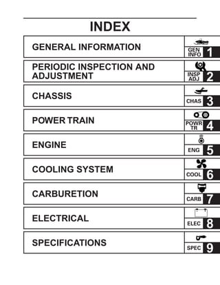
1. GENERAL INFORMATION
PERIODIC INSPECTION AND
ADJUSTMENT
CHASSIS
POWER TRAIN
ENGINE
COOLING SYSTEM
CARBURETION
ELECTRICAL
SPECIFICATIONS
INDEX
GEN
INFO
CHAS
ENG
POWR
TR
CARB
ELEC
SPEC
COOL
1
INSP
ADJ 2
3
4
5
6
7
8
9
– +
2. CHAPTER 1.
GENERAL INFORMATION
MACHINE IDENTIFICATION............................ 1-1
FRAME SERIAL NUMBER......................... 1-1
ENGINE SERIAL NUMBER ....................... 1-1
IMPORTANT INFORMATION .......................... 1-2
PREPARATION FOR REMOVAL AND
DISASSEMBLY .......................................... 1-2
ALL REPLACEMENT PARTS .................... 1-2
GASKETS, OIL SEALS, AND O-RINGS .... 1-3
LOCK WASHERS/PLATES AND COTTER
PINS ........................................................... 1-3
BEARINGS AND OIL SEALS ..................... 1-3
CIRCLIPS ................................................... 1-3
LOCTITE®
................................................... 1-3
SPECIAL TOOLS ............................................. 1-4
FOR TUNE UP ........................................... 1-4
FOR ENGINE SERVICE ............................ 1-5
FOR POWER TRAIN SERVICE ................. 1-5
FOR CARBURETION SERVICE ................ 1-6
FOR ELECTRICAL SERVICE .................... 1-6
CHAPTER 2.
PERIODIC INSPECTION AND
ADJUSTMENT
INTRODUCTION............................................... 2-1
PERIODIC MAINTENANCE TABLE ................ 2-1
ENGINE ............................................................ 2-3
SPARK PLUGS .......................................... 2-3
OIL PUMP .................................................. 2-4
FUEL LINE INSPECTION .......................... 2-6
COOLING SYSTEM ................................... 2-6
CARBURETOR SYNCHRONIZATION..... 2-12
ENGINE IDLE SPEED ADJUSTMENT .... 2-13
THROTTLE CABLE FREE PLAY
ADJUSTMENT ......................................... 2-13
THROTTLE OVERRIDE SYSTEM
(T.O.R.S.) CHECK.................................... 2-14
STARTER (CHOKE) CABLE FREE PLAY
ADJUSTMENT ......................................... 2-15
EXHAUST SYSTEM INSPECTION .......... 2-15
POWER TRAIN............................................... 2-16
SHEAVE DISTANCE AND OFFSET
ADJUSTMENT ......................................... 2-16
DRIVE V-BELT ......................................... 2-18
ENGAGEMENT SPEED CHECK ............. 2-20
PARKING BRAKE PAD INSPECTION ..... 2-20
PARKING BRAKE ADJUSTMENT ........... 2-20
BRAKE LEVER ADJUSTMENT
(VX700DX/SX700/VT700) ........................ 2-21
BRAKE FLUID LEVEL INSPECTION ....... 2-21
BRAKE PAD INSPECTION ...................... 2-22
BRAKE HOSE INSPECTION ................... 2-22
AIR BLEEDING
(HYDRAULIC BRAKE SYSTEM) ............. 2-22
DRIVE CHAIN .......................................... 2-23
TRACK TENSION ADJUSTMENT ........... 2-26
SLIDE RUNNER INSPECTION ................ 2-28
MAXIMIZING DRIVE TRACK LIFE .......... 2-29
CHASSIS ........................................................ 2-30
SKI/SKI RUNNER ..................................... 2-30
STEERING SYSTEM ............................... 2-31
LUBRICATION ......................................... 2-32
ELECTRICAL ................................................. 2-34
HEADLIGHT BEAM ADJUSTMENT......... 2-34
BATTERY INSPECTION
(VX700DX/VT700) .................................... 2-35
BATTERY CHARGING
(VX700DX/VT700) .................................... 2-37
FUSE INSPECTION (VX700DX/VT700) .. 2-38
TUNING .......................................................... 2-40
CARBURETOR TUNING .......................... 2-40
CLUTCH ................................................... 2-47
GEAR SELECTION .................................. 2-52
HIGH ALTITUDE TUNING ....................... 2-58
FRONT SUSPENSION............................. 2-59
REAR SUSPENSION ............................... 2-60
CHAPTER 3.
CHASSIS
STEERING ........................................................ 3-1
VX700/VX700DX/SX700/VT700................. 3-1
MM700........................................................ 3-2
INSPECTION .............................................. 3-4
INSTALLATION .......................................... 3-5
6. 1-1
GEN
INFOMACHINE IDENTIFICATION
GENERAL INFORMATION
MACHINE IDENTIFICATION
FRAME SERIAL NUMBER
Theframeserialnumber1islocatedontheright-handsideoftheframe(just
below the front of the seat).
ENGINE SERIAL NUMBER
The engine serial number 1 is located on the right-hand side of the
crankcase.
NOTE:
Designs and specifications are subject to change without notice.
SCH1010
SCH1020
7. 1-2
GEN
INFOIMPORTANT INFORMATION
IMPORTANT INFORMATION
PREPARATION FOR REMOVAL AND DISASSEMBLY
1. Remove all dirt, mud, dust, and foreign material before removal and
disassembly.
While cleaning, take care to protect the electrical parts, such as relays,
switches, motor, resistors, controllers, etc., from high pressure water
splashes.
2. Use proper tools and cleaning equipment.
Refer to “SPECIAL TOOLS”.
3. When disassembling the machine, keep mated parts together. This
includes gears, cylinders, pistons, and other parts that have been
“mated” through normal wear. Mated parts must be reused or replaced
as an assembly.
4. During disassembly of the machine, clean all parts and place them in
trays in the order of disassembly. This will speed up assembly time and
help ensure that all parts are reinstalled correctly.
5. Keep all parts away from any source of fire.
6. Be sure to keep to the tightening torque specifications. When tightening
bolts, nuts, and screws, start with those that have larger diameters, and
proceed from the inside to the outside in a crisscross pattern.
ALL REPLACEMENT PARTS
We recommend using genuine Yamaha parts for all replacements. Use oil
and grease recommended by Yamaha for assembly and adjustments.
SCH1030
SCH1040
SCH1050
SCH1060
SCH1070
SCH1080
8. 1-3
GEN
INFOIMPORTANT INFORMATION
GASKETS, OIL SEALS, AND O-RINGS
1. All gaskets, seals, and O-rings should be replaced when an engine is
overhauled. All gasket surfaces, oil seal lips, and O-rings must be
cleaned.
2. Properly oil all mating parts and bearings during reassembly. Apply
grease to the oil seal lips.
LOCK WASHERS/PLATES AND COTTER PINS
All lock washers/plates 1 and cotter pins must be replaced if they are
removed. Lock tab(s) should be bent along the bolt or nut flat(s) after the bolt
or nut has been properly tightened.
BEARINGS AND OIL SEALS
Install the bearings 1 and oil seals 2 with their manufacturer’s marks or
numbers facing outwards. (In other words, the stamped letters must be on
the side exposed to view.) When installing oil seals, apply a light coating of
lightweightlithiumbasegreasetotheseallips.Oilthebearingsliberallywhen
installing.
CAUTION:
Do not use compressed air to spin the bearings dry. This causes
damage to the surface of the bearings.
CIRCLIPS
All circlips should be inspected carefully before reassembly. Always replace
piston pin clips after one use. Replace misshapen circlips. When installing
a circlip 1, make sure that the sharp edged corner 2 is positioned opposite
to the thrust 3 it receives. See the sectional view.
4 Shaft
LOCTITE®
After installing fasteners that have LOCTITE®
applied, wait 24 hours before
using the machine. This will give the LOCTITE®
time to dry properly.
SCH1090
SCH1100
SCH1110
SCH1120
9. 1-4
GEN
INFOSPECIAL TOOLS
SPECIAL TOOLS
Some special tools are necessary for a completely accurate tune-up and
assembly. Using the correct special tool will help prevent damage that can
be caused by the use of improper tools or improvised techniques.
NOTE:
Be sure to use the correct part number when ordering the tool, since the part
number may differ according to country.
FOR TUNE UP
• Sheave gauge
P/N: YS-42421-1 (15 mm offset) 1
YS-42421-2 (20 mm offset) 2
This gauge is used to measure the sheave distance and for offset adjust-
ment.
• Dial gauge
P/N: YU-03097 (for U.S.A./Canada)
90890-03097 (for Europe)
This gauge is used for run out measurement.
• Fuel level gauge
P/N: YM-01312-A (for U.S.A./Canada)
90890-01312 (for Europe)
This gauge is used to measure the fuel level in the float chamber.
• Distance gauge
P/N: YS-91047-3 (for U.S.A./Canada)
90890-01702 (for Europe)
This gauge is used to measure the distance between the center of the
primary sheave and the center of the secondary sheave.
SCH1130
SCH1160
SCH1150
SCH1140
10. 1-5
GEN
INFO
FOR ENGINE SERVICE
• Piston pin puller
P/N: YU-01304 (for U.S.A./Canada)
90890-01304 (for Europe)
This tool is used to remove the piston pin.
• Rotor holding puller
P/N: YU-33270 (for U.S.A./Canada)
90890-01362 (for Europe)
This tool is used to remove the magneto rotor.
• Cooling system tester
P/N: YU-24460-01 (for U.S.A./Canada)
90890-01325 (for Europe)
This tester is used for checking the cooling system.
FOR POWER TRAIN SERVICE
• Primary sheave holder
P/N: YS-01880 (for U.S.A./Canada)
90890-01701 (for Europe)
This tool is used to hold the primary sheave.
• Primary sheave puller (18 mm)
P/N: YS-01881-11, YS-01882-12
This tool is used for removing the primary sheave.
• Clutch spider separator
P/N: YS-28890-B (for U.S.A./Canada)
90890-01711 (for Europe)
This tool is used when disassembling and assembling the primary sheave.
• Clutch separator adapter
P/N: YS-34480 (for U.S.A./Canada)
90890-01740 (for Europe)
This tool is used when disassembling and assembling the primary sheave.
• YXR clutch bushing jig kit
P/N: YS-39752
This tool is used for removal and installation of primary clutch weight and
roller bushings.
SPECIAL TOOLS
SCH1170
SCH1180
SCH1190
SCH1200
SCH1210
SCH1220
SCH1230
SCH1240
11. 1-6
GEN
INFOSPECIAL TOOLS
• Clutch bushing press
P/N: YS-42424
This tool is used for removing and installing the post bushings (primary
sheave cap bush, sliding sheave bush and torque cam bush).
• Track clip installer
P/N: YS-91045-A (for U.S.A./Canada)
90890-01721 (for Europe)
This tool is used for installing the track clip.
• Angle finder
P/N: YS-42422
This tool is used for checking and adjusting the ski spindle camber.
FOR CARBURETION SERVICE
• Mity vac
P/N: YB-35956 (for U.S.A./Canada)
90890-06756 (for Europe)
This tool is used to check the fuel pump.
FOR ELECTRICAL SERVICE
• Pocket tester
P/N: YU-03112 (for U.S.A./Canada)
90890-03112 (for Europe)
This instrument is necessary for checking the electrical components.
• Electro tester
P/N: YU-33260-A (for U.S.A./Canada)
90890-03021 (for Europe)
This instrument is invaluable for checking the electrical system.
SCH1250
SCH1260
SCH1270
SCH1280
SCH1290
SCH1300
12. 2-1
INSP
ADJINTRODUCTION/PERIODIC MAINTENANCE TABLE
PERIODIC INSPECTION AND ADJUSTMENT
INTRODUCTION
This chapter includes all information necessary to perform recommended inspections and adjustments. These
preventivemaintenanceprocedures,iffollowed,willensuremorereliablemachineoperationandalongerservice
life. In addition, the need for costly overhaul work will be greatly reduced. This information applies to machines
already in service as well as new machines that are being prepared for sale. All service technicians should be
familiar with this entire chapter.
PERIODIC MAINTENANCE TABLE
Item Remarks
Spark plugs
Engine oil
Fuel
Fuel filter
Fuel line
Oil line
Engine coolant
Carburetors
Recoil starter
Engine stop switch
Throttle override system
(T.O.R.S.)
Throttle lever
Exhaust system
Decarbonization
Drive guard
V-belt
Drive track and idler wheels
Slide runners
Pre-
operation
check
(Daily)
Initial
1 month
or
800 km
(500 mi)
(40 hr)
Every
Seasonally
or
3,200 km
(2,000 mi)
(160 hr)
Check condition. Adjust gap and clean.
Replace if necessary.
Check oil level.
Air bleed the oil pump if necessary.
Check fuel level.
Check condition.
Replace if necessary.
Check fuel hose for cracks or damage.
Replace if necessary.
Check oil hose for cracks or damage.
Replace if necessary.
Check coolant level.
Air bleed the cooling system if necessary.
Check throttle lever operation.
Adjust the jets.
Check operation and rope damage.
Replace if necessary.
Check operation
Repair if necessary.
Check operation.
Repair if necessary.
Check operation.
Repair if necessary.
Check for leakage.
Retighten or replace gasket if necessary.
More frequently if necessary.
Check for cracks, bends or damage.
Replace if necessary.
Check for wear and damage.
Replace if necessary.
Check deflection, and for wear and damage.
Adjust/replace if necessary.
Check for wear and damage.
Replace if necessary.
Whenever operating condition
(elevation/temperature) is changed.
13. 2-2
INSP
ADJPERIODIC MAINTENANCE TABLE
Check operation and fluid leakage.
Adjust free play and/or replace pads if necessary.
Replace brake fluid.
Check oil level.
Replace.
Check deflection.
Adjust if necessary.
Check for wear and damage.
Replace if necessary.
Check operation.
Adjust toe-out if necessary.
Check for damage.
Replace if necessary.
Check operation.
Replace bulbs if necessary.
Check fluid level.
Add only distilled water if necessary.
Check specific gravity and breather hose operation.
Charge/correct if necessary.
Whenever operating elevation is changed.
Initial at 500 km (300 mi) and every 800 km
(500 mi) thereafter.
See NOTE.
Brake and parking brake
Drive chain oil
Drive chain
Skis and ski runners
Steering system
Strap (MM700)
Lights
Battery
(VX700DX/VT700)
NOTE:
Brake fluid replacement:
1. When disassembling the master cylinder or caliper cylinder, replace the brake fluid. Normally check the brake
fluid level and add the fluid as required.
2. On the inner parts of the master cylinder and caliper cylinder, replace the oil seals every two years.
3. Replace the brake hoses every four years, or if cracked or damaged.
Item Remarks
Pre-
operation
check
(Daily)
Initial
1 month
or
800 km
(500 mi)
(40 hr)
Every
Seasonally
or
3,200 km
(2,000 mi)
(160 hr)
Lubricate with specified grease.
Lubricate with specified grease.
Lubricate with specified grease.
Lubricate with specified grease.
Check cable damage.
Replace if necessary.
Make sure that the shroud latches are hooked.
Check tightness.
Repair if necessary.
Check proper placement.
Primary and secondary
clutches
Check engagement and shift speed.
Adjust if necessary.
Inspect sheaves for wear/damege.
Inspect weights/rollers and bushings for wear-
for primary.
Inspectrampshoes/bushingsforwear-forsec-
ondary.
Replace if necessary.
Lubricate with specified grease.
Steering column bearing
Ski and front suspension
Suspension component
Parking brake cable end
and lever end/throttle cable
end
Shroud latches
Fittings and fasteners
Tool kit and recommended
equipment
14. 2-3
INSP
ADJSPARK PLUGS
ENGINE
SPARK PLUGS
1. Remove:
• Spark plug caps
• Spark plugs
2. Inspect:
• Electrodes 1
Damage/wear → Replace the spark plug.
• Insulator color 2
3. Measure:
• Spark plug gap a
Out of specification → Regap.
Use a wire thickness gauge.
Spark plug gap a:
0.7 ~ 0.8 mm (0.028 ~ 0.031 in)
If necessary, clean the spark plugs with a spark plug
cleaner.
Standard spark plug:
BR9ES (NGK)
Before installing a spark plug, clean the gasket sur-
face and spark plug surface.
4. Install:
• Spark plugs
Spark plug:
20 Nm (2.0 m · kg, 14 ft · lb)
NOTE:
Finger-tighten a the spark plug before torquing b it
to specification.
T
R
.
.
SCH2010
SCH2020
SCH2030
15. 2-4
INSP
ADJ
1
1
1
OIL PUMP
OIL PUMP
Air bleeding
CAUTION:
The oil pump and oil delivery line must be bled in
the following cases:
• Any portion of the oil system has been
disconnected.
• The machine has been turned on its side.
• The oil tank has been run empty.
• As part of the pre-delivery service.
1. Fill:
• Oil tank 1
Recommended oil:
YAMALUBE 2-cycle oil
Oil tank capacity:
3.0 L (2.6 Imp qt, 3.2 US qt)
2. Remove:
• Carburetors
Refer to “CARBURETORS” in CHAPTER 7.
3. Remove:
• Rear bracket (right) 1
4. Place a rag under the oil pump assembly to soak
up any spilled oil.
5. Disconnect:
• Oil hose
6. Drain the oil until no more air bubbles appear in
the oil hose.
7. Connect:
• Oil hose
8. Disconnect:
• Oil delivery hose
9. Feed the “YAMALUBE 2-cycle oil” into the oil
delivery hose using an oil can for complete air
bleeding.
10. Connect:
• Oil delivery hose
11. Remove:
• Bleed bolt 1
• Gasket (bleed bolt)
12. Draintheoiluntilnomoreairbubblesappearfrom
the bleed hole.
13. Inspect:
• Gasket (bleed bolt)
Damage/wear → Replace.
SCH2050
SCH2060
SCH2040
16. 2-5
INSP
ADJOIL PUMP
14. Install:
• Gasket (bleed bolt)
• Bleed bolt
15. Install:
• Rear bracket (right)
M8 mounting bolt (rear):
33 Nm (3.3 m · kg, 24 ft · lb)
M10 mounting bolt (rear):
57 Nm (5.7 m · kg, 41 ft · lb)
16. Install:
• Carburetors
Refer to “CARBURETORS” in CHAPTER 7.
Cable adjustment
NOTE:
Before adjusting the oil pump cable, the throttle cable
free play should be adjusted.
Adjustment steps:
• Slide back the adjuster cover.
• Loosen the locknut 1.
• Turn the adjuster 2 in or out until the specified
distance a is obtained.
Distance a:
22 ± 1 mm (0.866 ± 0.039 in)
Turning in → Distance a is increased.
Turning out → Distance a is decreased.
• Tighten the locknut and push in the adjuster
cover.
SCH2070
SCH2080
T
R
.
.
17. 2-6
INSP
ADJ
2
2
1
FUEL LINE INSPECTION/COOLING SYSTEM
FUEL LINE INSPECTION
1. Remove:
• Intake silencer
Refer to “FUEL PUMP” in CHAPTER 7.
2. Inspect:
• Fuel hose 1
• Fuel delivery hoses 2
Cracks/damage → Replace.
3. Install:
• Intake silencer
Refer to “FUEL PUMP” in CHAPTER 7.
COOLING SYSTEM
Coolant replacement
NOTE:
The coolant should be changed at least every sea-
son.
1. Place the machine on a level surface.
2. Remove:
• Exhaust pipe
• Exhaust joint
Refer to “EXHAUST ASSEMBLY” in CHAP-
TER 5.
3. Make sure that the carburetor heating lever 1 is
turned to “ON” a.
SCH2090
SCH2100
SCH2110
18. 2-7
INSP
ADJ
1
1
4. Remove:
• Coolant filler cap 1
WARNING
Do not remove the coolant filler cap 1 when the
engine is hot. Pressurized scalding hot fluid and
steam may be blown out, which could cause
seriousinjury.Whentheenginehascooled,place
a thick rag or a towel over the coolant filler cap.
Slowly turn the cap counterclockwise until it
stop. This allows any residual pressure to es-
cape.Whenthehissingsoundhasstopped,press
down on the cap while turning it counterclock-
wise to remove it.
5. Place an open container under the coolant drain
bolt 1.
6. Remove:
• Coolant drain bolt
• Gasket (coolant drain bolt)
7. Drain the coolant.
NOTE:
Lift up the tail of the machine to drain the coolant.
8. Remove:
• Right side cover 1 (MM700)
COOLING SYSTEM
SCH2120
SCH2130
SCH2140
19. 2-8
INSP
ADJ
1
1
1
1
9. Disconnect:
• Coolant hoses 1
Å VX700/VX700DX/SX700/VT700
ı MM700
10. Drain the coolant.
NOTE:
Lift up the front of the machine to drain the coolant
completely.
WARNING
Coolant is poisonous. It is harmful or fatal if
swallowed.
• If coolant is swallowed, induce vomiting imme-
diately and get immediate medical attention.
• If coolant splashes in your eyes, thoroughly
wash them with water and consult a doctor.
• If coolant splashes on your skin or clothes,
quickly wash it away with soap and water.
11. Connect:
• Coolant hoses
12. Install:
• Right side cover 1 (MM700)
Bolt (side cover):
3 Nm (0.3 m · kg, 2.2 ft · lb)
13. Disconnect:
• Coolant reservoir hose 1
14. Remove:
• Coolant reservoir cap 1
15. Drain the coolant from the coolant reservoir.
16. Install:
• Coolant reservoir cap
17. Connect:
• Coolant reservoir hose
COOLING SYSTEM
T
R
.
.
SCH2140
SCH2160
SCH2150
A
B
SCH2180
SCH2190
20. 2-9
INSP
ADJCOOLING SYSTEM
T
R
.
.
SCH2130
T
R
.
.
18. Inspect:
• Gasket (coolant drain bolt)
Damage → Replace.
19. Install:
• Gasket
• Coolant drain bolt 1
Coolant drain bolt 1:
13 Nm (1.3 m · kg, 9.4 ft · lb)
20. Install:
• Exhaust joint
• Exhaust pipe
Refer to “EXHAUST ASSEMBLY” in CHAP-
TER 5.
Bolt (exhaust joint) 1:
1st:
18 Nm (1.8 m · kg, 13 ft · lb)
2nd:
27 Nm (2.7 m · kg, 19 ft · lb)
21. Fill:
• Cooling system
Recommended coolant:
High quality ethylene glycol
antifreeze containing
corrosion inhibitors
Coolant mixing ratio (coolant:water)
3:2 (60%:40%)
Total amount:
VX700/VX700DX/SX700:
3.8 L (3.34 lmp qt, 4.02 US qt)
MM700:
3.9 L (3.43 lmp qt, 4.12 US qt)
VT700:
4.0 L (3.52 lmp qt, 4.23 US qt)
Reservoir tank capacity:
0.28 L (0.25 lmp qt, 0.30 US qt)
From LOW to FULL level:
0.13 L (0.11 lmp qt, 0.14 US qt)
CAUTION:
• Hard water or salt water is harmful to engine
parts.Ifsoftwaterisnotavailable,useboiledor
distilled water.
• Do not use water containing impurities or oil.
SCH2210
21. 2-10
INSP
ADJ
1
1
1
2
22. Bleed the air from the cooling system.
23. Inspect:
• Cooling system
Decrease of pressure (leaks) → Repair as
required.
Inspection steps:
• Attach the cooling system tester 1 to the coolant
filler 2.
Cooling system tester:
90890-01325, YU-24460-01
• Apply 100 kPa (1.0 kg/cm2
, 14 psi).
• Measure the pressure with the gauge.
Air bleeding
1. Remove:
• Seat (VX700/VX700DX/SX700/VT700)
• Rear bumper cover 1 (VT700)
• Bleed bolt cap 1 (MM700)
Å VT700
ı MM700
2 .Bleed air from the cooling system.
COOLING SYSTEM
SCH2220
SCH2225
SCH2230
A
B
22. 2-11
INSP
ADJ
1
COOLING SYSTEM
Air bleeding steps:
• Lift up the tail of the machine.
• Remove the bleed bolt 1 on the heat exchanger.
• While slowly adding coolant to the coolant filler,
drain the coolant until no more air bubbles ap-
pear.
• Tighten the bleed bolt 1.
Bleed bolt 1:
VX700/VX700DX/SX700/VT700:
13 Nm (1.3 m · kg, 9.4 ft · lb)
MM700:
4 Nm (0.4 m · kg, 2.9 ft · lb)
Å VX700/VX700DX/SX700/VT700
ı MM700
• Add coolant to the coolant cold level a.
• Loosen the bleed bolt 2 on the thermostatic
cover.
• Drain the coolant until no more air bubbles ap-
pear.
• Tighten the bleed bolt 2.
Bleed bolt 2:
7 Nm (0.7 m · kg, 5.1 ft · lb)
• Install the coolant filler cap.
Applyandlocktheparkingbrake.Starttheengine
and run it at approximately 2,500 ~ 3,000 r/min
until the coolant circulates (approximately 3 ~
5 minutes). The rear heat exchanger will be warm
to the touch.
WARNING
To avoid severe injury or death:
• Make sure the machine is securely sup-
ported with a suitable stand.
• Donotexceed3,000r/min.Drivelinedamage
and excessive V-belt wear could occur, or
the machine could unexpectedly move for-
ward if the clutch engages.
• Operate the engine only in a well-ventilated
area.
T
R
.
.
SCH2260
SCH2240
SCH2250
A
B
T
R
.
.
23. 2-12
INSP
ADJ
3
• Remove the coolant filler cap and bleed the
cooling system again, as described above.
No air bubbles → OK.
• Add coolant to the specified level.
• Pour coolant into the coolant reservoir 3 until
the coolant level reaches the “FULL” level mark.
3. Install:
• Bleed bolt cap (MM700)
• Seat (VX700/VX700DX/SX700/VT700)
CARBURETOR SYNCHRONIZATION
1. Remove:
• Carburetors
Refer to “CARBURETORS” in CHAPTER 7.
2. Adjust:
• Carburetor synchronization
Adjustment steps:
• Turn the throttle stop screw 1 of carburetor #2
until the specified throttle valve height a is ob-
tained.
Throttle valve height a:
1.2 mm (0.047 in)
• Adjust the throttle valve height a on carburetor
#1 2 and #3 3 with the adjusting screws 4.
• Move the throttle lever 2 ~ 3 times.
• Make sure that all of the carburetor throttle valves
are at the same height.
3. Install:
• Carburetors
Refer to “CARBURETORS” in CHAPTER 7.
COOLING SYSTEM/
CARBURETOR SYNCHRONIZATION
SCH2280
SCH2290
SCH2270
24. 2-13
INSP
ADJ
ENGINE IDLE SPEED ADJUSTMENT
1. Adjust:
• Engine idle speed
Adjustment steps:
• Start the engine and let it warm up.
• Turn the throttle stop screw 1 in or out until the
specified engine idle speed is obtained.
Turning in → Idle speed is increased.
Turning out → Idle speed is decreased.
Engine idle speed:
1,600 ± 100 r/min
NOTE:
After adjusting the engine idle speed, the throttle
cable free play should be adjusted.
THROTTLE CABLE FREE PLAY
ADJUSTMENT
NOTE:
• Before adjusting the throttle cable free play, the
engine idle speed should be adjusted.
• Adjust the throttle cable free play while the cable is
in the cable guide.
1. Measure:
• Throttle cable free play a
Out of specification → Adjust.
Throttle cable free play a:
1.0 ~ 2.0 mm (0.04 ~ 0.08 in)
SCH2310
SCH2300
ENGINE IDLE SPEED ADJUSTMENT/
THROTTLE CABLE FREE PLAY ADJUSTMENT
25. 2-14
INSP
ADJ
1
2
3
2. Adjust:
• Throttle cable free play
Adjustment steps:
• Loosen the locknut 1.
• Turn the adjusting nut 2 in or out until the
specified free play is obtained.
Turning in → Free play is increased.
Turning out → Free play is decreased.
• Tighten the locknut.
NOTE:
After adjusting the free play, turn the handlebar to
right and left, and make sure that the engine idling
does not run faster.
THROTTLE OVERRIDE SYSTEM (T.O.R.S.)
CHECK
WARNING
When checking T.O.R.S.:
• Be sure the parking brake is applied.
• Be sure the throttle lever moves smoothly.
• Do not run the engine up to the clutch engage-
mentspeed.Otherwise,themachinecouldstart
moving forward unexpectedly, which could
cause an accident.
1. Start the engine.
2. Hold the pivot point of the throttle lever away from
the throttle switch by putting your thumb (above)
and forefinger (below) between the throttle lever
pivot 1 and stop switch housing 2.
While holding as described above, press the
throttle lever 3 gradually.
The T.O.R.S. will operate and the engine should
run between 2,800 and 3,000 r/min.
WARNING
If the engine does not run between 2,800 and
3,000 r/min, stop the engine by turning the main
switch to the “OFF” position and check the elec-
trical system.
SCH2330
SCH2320
THROTTLE CABLE FREE PLAY ADJUSTMENT/
THROTTLE OVERRIDE SYSTEM (T.O.R.S.) CHECK
26. 2-15
INSP
ADJ
STARTER (CHOKE) CABLE FREE PLAY ADJUSTMENT/
EXHAUST SYSTEM INSPECTION
STARTER (CHOKE) CABLE FREE PLAY
ADJUSTMENT
1. Measure:
• Starter cable free play a
Out of specification → Adjust.
Starter cable free play a:
0.5 ~ 1.5 mm (0.02 ~ 0.06 in)
2. Adjust:
• Starter cable free play
Adjustment steps:
• Loosen the locknut 1.
• Turn the adjusting nut 2 in or out until the
specified free play is obtained.
Turning in → Free play is increased.
Turning out → Free play is decreased.
• Tighten the locknut.
EXHAUST SYSTEM INSPECTION
1. Open the shroud.
2. Remove:
• Springs
Refer to “EXHAUST ASSEMBLY” in CHAP-
TER 5.
3. Inspect:
• Exhaust joint 1
• Exhaust pipe 2
• Exhaust silencer 3
Cracks/damage → Replace.
• Gasket 1 4
• Gasket 2 5
• Gasket 3 6
Exhaust gas leaks → Replace.
4. Check:
• Tightening torque 7
Bolt (exhaust joint) 7:
1st:
18 Nm (1.8 m · kg, 13 ft · lb)
2nd:
27 Nm (2.7 m · kg, 19 ft · lb)
5. Install:
• Springs
Refer to “EXHAUST ASSEMBLY” in CHAP-
TER 5.
T
R
.
.
SCH2340
SCH2350
27. 2-16
INSP
ADJ
2
SHEAVE DISTANCE AND OFFSET ADJUSTMENT
POWER TRAIN
SHEAVE DISTANCE AND OFFSET
ADJUSTMENT
1. Open the shroud.
2. Remove:
• Drive V-belt guard
• Drive V-belt
3. Measure:
• Sheave distance a
Use the distance gauge.
Out of specification → Adjust.
Sheave distance a:
267 ~ 270 mm (10.52 ~ 10.62 in)
Distance gauge:
90890-01702, YS-91047-3
4. Measure:
• Sheave offset a
Use the sheave gauge.
Out of specification → Adjust.
Sheave offset a:
VX700/SX700/MM700:
13.5 ~ 16.5 mm (0.53 ~ 0.64 in)
VX700DX/VT700
18.5 ~ 21.5 mm (0.73 ~ 0.85 in)
Sheave gauge:
YS-42421-1 (15 mm offset)
YS-42421-2 (20 mm offset)
5. Adjust:
• Sheave distance
Adjustment steps:
• Loosen the engine mounting bolts.
• Adjust the position of the engine so that the
sheave distance is within the specification.
• Tighten the engine mounting bolts.
Mounting bolt (front) 1:
90 Nm (9.0 m · kg, 65 ft · lb)
Mounting bolt (rear) 2:
57 Nm (5.7 m · kg, 41 ft · lb)
SCH2360
SCH2380
SCH2370
T
R
.
.
SCH2390
28. 2-17
INSP
ADJ
1
2
3
a
6. Measure:
• Secondary sheave free play (clearance) a
Use a thickness gauge.
Out of specification → Adjust.
Secondary sheave free play
(clearance) a:
1.0 ~ 2.0 mm (0.04 ~ 0.08 in)
7. Adjust:
• Secondary sheave free play (clearance)
Adjustment steps:
• Apply the brake to lock the secondary sheave.
• Remove the bolt 1 and washer 2.
• Adjust the secondary sheave free play (clear-
ance) by adding or removing a shim(s) 3.
Shim size:
Part number Thickness
90201-222F0 0.5 mm (0.02 in)
90201-225A4 1.0 mm (0.04 in)
SHEAVE DISTANCE AND OFFSET ADJUSTMENT
SCH2400
SCH2410
29. 2-18
INSP
ADJDRIVE V-BELT
DRIVE V-BELT
WARNING
When installing the new V-belt, make sure that it
is positioned from 1.5 mm (0.06 in) above the
edge of the secondary sheave to –0.5 mm
(–0.02 in) below the edge a.
If the V-belt is not positioned correctly, the clutch
engagementspeedwillbechanged.Themachine
may move unexpectedly when the engine is
started.
Adjust the V-belt position by removing or adding
a spacer 1 on each adjusting bolt 2.
CAUTION:
As the V-belt wears, adjustment may be neces-
sary. To ensure proper clutch performance, the V-
beltpositionshouldbeadjustedbyaddingaspacer
on each adjusting bolt when the V-belt position
reaches 1.5 mm (0.06 in) below the edge.
New belt width:
34.5 mm (1.36 in)
Belt wear limit width:
32.5 mm (1.28 in)
1. Measure:
• V-belt position a
NOTE:
Install the new V-belt onto the secondary sheave
only. Do not force the V-belt between the sheaves;
the sliding and fixed sheaves must touch each other.
Standard V-belt height a:
–0.5 ~ 1.5 mm (–0.02 ~ 0.06 in)
SCH2430
SCH2420
30. 2-19
INSP
ADJDRIVE V-BELT
2. Adjust the position of the V-belt by removing or
adding a spacer 1 on each adjusting bolt 2.
V-belt position
More than 1.5 mm
(0.06 in) above the
edge
From 1.5 mm (0.06 in)
above the edge to
–0.5 mm (–0.02 in)
below the edge
More than –0.5 mm
(–0.02 in) below the
edge
3. Tighten:
• Adjusting bolt 2
Adjusting bolt 2:
10 Nm (1.0 m · kg, 7.2 ft · lb)
4. Inspect:
• Drive V-belt
Cracks/damage/wear → Replace.
Oil or grease on the V-belt → Check the pri-
mary and secondary sheaves.
5. Inspect:
• Primary sheave
• Secondary sheave
Oil or grease on the primary and secondary
sheaves→ Usearagsoakedinlacquerthinner
or solvent to remove the oil or grease. Check
the primary and secondary sheaves.
6. Measure:
• Drive V-belt circumference a
Out of specification → Replace.
V-belt circumference a:
1,129 ~ 1,137 mm (44.4 ~ 44.7 in)
Adjustment
Remove a spacer
Not necessary
(It is correct.)
Add spacer
T
R
.
.
SCH2440
SCH2450
SCH2460
SCH2470
31. 2-20
INSP
ADJ
ENGAGEMENT SPEED CHECK
1. Place the machine on a level surface of hard-
packed snow.
2. Check:
• Clutch engagement speed
Checking steps:
• Start the engine, and open the throttle lever
gradually.
• Check the engine speed when the machine starts
moving forward.
Out of specification → Adjust the primary sheave.
Engagement speed:
VX700/VX700DX:
4,000 ± 200 r/min
(3,800 ~ 4,200 r/min)
SX700/VT700:
3,900 ± 200 r/min
(3,700 ~ 4,100 r/min)
MM700:
4,700 ± 200 r/min
(4,500 ~ 4,900 r/min)
PARKING BRAKE PAD INSPECTION
1. Measure:
• Parking brake pad thickness a
Out of specification → Replace as a set.
Wear limit a:
6.0 mm (0.24 in)
PARKING BRAKE ADJUSTMENT
1. Measure:
• Clearance a
Out of specification → Adjust.
Clearance a:
1.2 ~ 1.3 mm (0.047 ~ 0.051 in)
2. Adjust:
• Clearance a
Adjustment steps:
• Loosen the locknuts 1.
• Turn the cable adjuster 2 in or out to until the
specified clearance between the brake pad 3
and disc 4 is obtained.
• Turn the brake pad adjusting bolt 5 in or out until
the specified clearance between the brake pad6
and disc 4 is obtained.
• Tighten the locknuts.
ENGAGEMENT SPEED CHECK/PARKING BRAKE PAD
INSPECTION/PARKING BRAKE ADJUSTMENT
SCH2480
SCH2490
SCH2500
32. 2-21
INSP
ADJ
BRAKE LEVER ADJUSTMENT
(VX700DX/SX700/VT700)
1. Adjust:
• Brake lever position
(distance from the grip to the brake lever)
Adjustment steps:
• Loosen the locknut 1.
• Whilelightlypushingthebrakeleverindirectiona,
turn the adjusting bolt2 by fingers to set the brake
lever to the desired position.
• Tighten the locknut securely after adjusting.
Locknut 1:
6 Nm (0.6 m · kg, 4.3 ft · lb)
BRAKE FLUID LEVEL INSPECTION
1. Place the machine on a level surface.
2. Check:
• Fluid level
Fluid level is under the “LOWER” level line a
→ Fill to the proper level.
Recommended brake fluid:
DOT 4
NOTE:
For a correct reading of the brake fluid level, make
sure that the top of the handlebar brake master
cylinder reservoir is horizontal.
CAUTION:
Brake fluid may corrode painted surfaces or plas-
tic parts. Always clean up spilled fluid immedi-
ately.
WARNING
• Use only the designated brake fluid. Other
fluids may deteriorate the rubber seals, caus-
ing leakage and poor brake performance.
• Refill with the same type of fluid. Mixing fluids
may result in a harmful chemical reaction lead-
ing to poor brake performance.
• When refilling, be careful that water does not
enter the brake master cylinder reservoir. Wa-
ter will significantly lower the boiling point of
the fluid and may cause vapor lock.
BRAKE LEVER ADJUSTMENT (VX700DX/SX700/VT700)/
BRAKE FLUID LEVEL INSPECTION
T
R
.
.
SCH2510
SCH2520
33. 2-22
INSP
ADJ
BRAKE PAD INSPECTION
1. Apply the brake lever.
2. Inspect:
• Brake pad
Wear indicator 1 nearly contacts the brake
disc → Replace as a set.
Wear limit a:
4.7 mm (0.19 in)
BRAKE HOSE INSPECTION
1. Inspect:
• Brake hose
Cracks/damage/wear → Replace.
2. Check:
• Fluid leakage
Apply the brake lever several times.
Fluid leakage → Replace the defective parts.
AIR BLEEDING
(HYDRAULIC BRAKE SYSTEM)
WARNING
Bleed the brake system in the following cases:
• The system has been disassembled.
• A brake hose is loosened or removed.
• The brake fluid has been very low.
• Brake operation is faulty.
If the brake system is not properly bled a loss of
braking performance may occur.
1. Bleed:
• Brake system
Air bleeding steps:
• Fill the brake master cylinder reservoir with the
proper brake fluid.
• Install the diaphragm. Be careful not to spill any
fluid or allow the brake master cylinder reservoir
to overflow.
• Connect clear plastic hoses 1 tightly to the brake
caliper bleed screws 2.
• Place the other ends of the hoses in a container.
a. Slowly apply the brake lever several times.
b. Pull the lever in, then hold the lever in position.
c. Loosen the bleed screws and allow the brake
lever to travel towards its limit.
BRAKE PAD INSPECTION/BRAKE HOSE INSPECTION
AIR BLEEDING (HYDRAULIC BRAKE SYSTEM)
SCH2530
SCH2540
34. 2-23
INSP
ADJ
1
d. Tighten the bleed screws when the brake lever
limit has been reached, then release the lever.
• Repeat steps (a) to (d) until all of the air bubbles
have disappeared from the fluid.
• Tighten the bleed screws.
Bleed screw 2:
6 Nm (0.6 m · kg, 4.3 ft · lb)
NOTE:
If bleeding is difficult, it may be necessary to let the
brake fluid settle for a few hours.
Repeatthebleedingprocedurewhenthetinybubbles
in the system have disappeared.
• Add brake fluid to the proper level.
Refer to “BRAKE FLUID LEVEL INSPECTION”.
WARNING
After bleeding the brake system, check the brake
operation.
DRIVE CHAIN
Oil level inspection
WARNING
The engine and muffler will be very hot after the
engine has run. Avoid touching a hot engine and
muffler while they are still hot with any part of
your body or clothing during inspection or repair.
1. Place the machine on a level surface.
2. Check:
• Oil level
Checking steps:
• Remove the dipstick 1 and wipe it off with a
clean rag.
Reinsert the dipstick.
T
R
.
.
SCH2550
AIR BLEEDING (HYDRAULIC BRAKE SYSTEM)/
DRIVE CHAIN
35. 2-24
INSP
ADJ
2
3
CAUTION:
There is a magnet attached to the end of the
dipstick. It is used to remove any metal particles
that may accumulate in the drive chain housing.
Be sure to:
• Pull the dipstick out slowly and gently so the
metal particles do not fall off the magnet back
into the drive chain housing.
• Wipe off the magnet before reinserting the
dipstick into the drive chain housing.
• Remove the dipstick and check that the oil is
between the upper a and lower b levels. If not,
add oil to the upper level.
Å For models without reverse transmissions
(VX700/SX700/MM700)
ı For models with reverse transmissions
(VX700DX/VT700)
Recommended oil:
Gear oil API “GL-3”
SAE #75 or #80
CAUTION:
Makesurethatnoforeignmaterialentersthegear
case.
• Reinsert the dipstick and fit the loop 2 of the
dipstick handle onto the projection 3 of the gear
case.
DRIVE CHAIN
A B
SCH2560
SCH2570
SCH2580
36. 2-25
INSP
ADJ
1
2
1
Oil replacement
Oil replacement steps:
• Place the oil pan under the drain hole.
• Remove the oil drain bolt 1 and drain the oil.
CAUTION:
Be sure to remove any oil from the heat protec-
tor.
• Install the oil drain bolt 1.
Oil drain bolt 1:
16 Nm (1.6 m · kg, 11 ft · lb)
Recommended oil:
Gear oil API “GL-3” SAE #75 or #80
Oil capacity:
0.25 L (8.8 Imp oz, 8.5 US oz)
Å VX700/VX700DX/SX700/VT700
ı MM700
Chain slack adjustment
1. Remove:
• Battery (VX700DX/VT700)
• Battery bracket (VX700DX/VT700)
WARNING
Whenremovingthebattery,disconnectthenega-
tive lead first.
2. Adjust:
• Drive chain slack
Adjustment steps:
• Loosen the locknut 1.
• Turn the adjusting bolt 2 in until it is finger tight.
• Tighten the locknut.
T
R
.
.
SCH2600
SCH2590
DRIVE CHAIN
SCH2610
A
B
37. 2-26
INSP
ADJ
3. Install:
• Battery bracket (VX700DX/VT700)
• Battery (VX700DX/VT700)
CAUTION:
• Connect the positive lead to the battery termi-
nal first.
• Make sure the battery leads are connected
properly. Reversing the leads can seriously
damage the electrical system.
• Make sure that the battery breather hose is
properly connected and is not obstructed.
TRACK TENSION ADJUSTMENT
WARNING
Abrokentrackortrackfittings,anddebristhrown
by the track could be dangerous to an operator or
by standers. Observe the following precautions.
• Do not allow anyone to stand behind the
machine when the engine is running.
• When the rear of the machine is raised to allow
the track to spin, a suitable stand must be used
to support the rear of the machine. Never allow
anyone to hold the rear of the machine off the
ground to allow the track to spin. Never allow
anyone near a rotating track.
• Inspect the condition of the track frequently.
Replace the track if it is damaged to a level
where the fabric reinforcement material is
visible.
• Never install studs (cleats) closer than 76 mm
(3 in) to the edge of the track.
1. Lift the rear of the machine onto a suitable stand
to raise the track off the ground.
2. Measure:
• Track deflection a
Usingaspringscale1,pulldownonthecenter
of the track with 10 kg (22 lb) of force.
Out of specification → Adjust.
Track deflection a:
VX700/VX700DX/SX700/VT700:
25 ~ 30 mm (0.98 ~ 1.18 in)
MM700:
20 ~ 25 mm (0.79 ~ 0.98 in)
DRIVE CHAIN/
TRACK TENSION ADJUSTMENT
SCH2620
38. 2-27
INSP
ADJ
4 5
TRACK TENSION ADJUSTMENT
3. Adjust:
• Track deflection
Adjustment steps:
• Place the machine onto a suitable stand to raise
the track off of the ground.
• Loosen the rear axle nut 1.
NOTE:
It is not necessary to remove the cotter pin 2.
a. Start the engine and rotate the track once or
twice. Stop the engine.
b. Checkthetrackalignmentwiththesliderunner3.
If the alignment is incorrect, turn the left and right
adjusters to adjust.
SCH2630
SCH2640
8 Slide runner 9 Track
0 Track metal A Gap B Forward
Å VX700/VX700DX/SX700/VT700
ı MM700
c. Adjust the track deflection until the specified
amount is obtained.
CAUTION:
The adjusters should be turned an equal amount.
• Recheck the alignment and deflection. If neces-
sary, repeat steps (a) to (c) until the specified
amount is obtained.
• Tighten the rear axle nut.
Nut (rear axle):
75 Nm (7.5 m · kg, 54 ft · lb)
Track alignment
4 Left adjuster
5 Right adjuster
6 Shifted
to right
Turn out
Turn in
7 Shifted
to left
Turn in
Turn out
Track deflection
4 Left adjuster
5 Right adjuster
More than
specified
Turn in
Turn in
Less than
specified
Turn out
Turn out
T
R
.
.
SCH2650
SCH2660
6 7
SCH2670
A
B
40. 2-29
INSP
ADJ
MAXIMIZING DRIVE TRACK LIFE
Recommendations
Track tension
During initial break-in, the new drive track will tend to
stretch quickly as the track settles. Be sure to correct
the track tension and alignment frequently. (See
pages 2-26 ~ 2-27 for adjustment procedures.) A
loose track can slip (ratchet), derail or catch on
suspension parts causing severe damage. Do not
overtighten the drive track, otherwise it may increase
the friction between the track and the slide runnners,
resulting in the rapid wear of both components. Also,
this may put an excessive load on the suspension
components, resulting in component failure.
Marginal snow
The drive track and the slide runners are lubricated
and cooled by snow and water. To prevent the drive
track and slide runners from overheating, avoid sus-
tained high-speed usage in areas such as icy trails,
frozen lakes and rivers that have minimal snow
coverage. An overheated track will be weakened
internally, which may cause failure or damage.
Off-trail riding
Avoid off-trail riding until there is sufficient snow
coverage. It generally takes several feet of snow to
provide a good overall base to properly cover debris,
such as rocks, logs, etc. If snow coverage is not
sufficient, stay on trails to avoid impact damage to the
drive track.
Studded track
In general, track life will be shortened when studs are
installed.Drillingstudholesintothedrivetrackwillcut
the internal fibers, which weakens the track. Avoid
spinning the drive track. Studs may catch on an
object and pull out of the track, leaving tears and
damage around the already weakened area. To
minimize possible damage, consult your stud manu-
facturer for installation and stud pattern recommen-
dations.
Yamaha does not recommend track studding.
MAXIMIZING DRIVE TRACK LIFE
41. 2-30
INSP
ADJ
a
CHASSIS
SKI/SKI RUNNER
1. Inspect:
• Ski
• Ski runner
Damage/wear → Replace.
Ski runner wear limit a:
8 mm (0.31 in)
Plastic ski wear limit b:
VX700/VX700DX/VT700:
13 mm (0.51 in)
SX700/MM700:
8 mm (0.31 in)
CAUTION:
To avoid scratching, wearing and damaging the
plastic skis, be careful when loading and unload-
ing the snowmobile and avoid riding in areas with
little or no snow and on surfaces with sharp
edges such as concrete, curbs, etc.
Å VX700/VX700DX/VT700
ı SX700/MM700
SCH2690
SCH2695
SCH2700
SCH2705
SKI/SKI RUNNER
A
A
B
B
42. 2-31
INSP
ADJ
STEERING SYSTEM
Free play check
1. Check:
• Steering system free play
Move the handlebar up and down and back
and forth.
Turn the handlebar slightly to the right and left.
Excessive free play → Check that the handle-
bar, tie rod ends and relay rod ends are in-
stalled securely in position. If free play still
exists, check the steering bearing, front sus-
pension links and ski mounting area for wear.
Replace if necessary.
Toe-out adjustment
1. Place the machine on a level surface.
2. Check:
• Ski toe-out
Point the skis forward.
Out of specification → Adjust.
Ski toe-out (a – c):
0 ~ 15 mm (0 ~ 0.59 in)
Ski stance b (center to center):
VX700/VX700DX/SX700/VT700:
1,070 mm (42.1 in)
MM700:
980 mm (38.6 in)
STEERING SYSTEM
SCH2710
SCH2715
43. 2-32
INSP
ADJSTEERING SYSTEM/LUBRICATION
A
T
R
.
.
B
3. Adjust:
• Ski toe-out
Adjustment steps:
• Loosen the locknuts (tie-rod) 1.
• Turn the tie rods 2in or out until the specified toe-
out is obtained.
• Tighten the locknuts (tie-rod) 1.
Locknut (rod end) 1:
25 Nm (2.5 m · kg, 18 ft · lb)
LOCTITE®
CAUTION:
After tightening the inside and outside ball joint
locknuts 1, make sure the tie rod 2 can be
rotated freely through the ball joint travel. If not,
loosenthelocknut1andre-positiontheballjoint
so that the tie rod 2 can be rotated freely. Tighten
the locknuts to specification.
Å Left side
ı Right side
Ç Inside
LUBRICATION
Brake lever, throttle lever and throttle cable end
1. Lubricate the brake lever pivot, throttle lever and
the ends of the throttle cables.
Recommended lubricant:
ESSO Beacon 325 Grease
WARNING
Apply a dab of grease onto only the end of the
cables.
Do not grease the throttle cables.
They could freeze and cause a loss of control.
SCH2720
SCH2725
C
SCH2730
SCH2735
44. 2-33
INSP
ADJLUBRICATION
B
C
Front and rear suspension
1. Use a grease gun to inject grease into the
nipples 1.
Recommended lubricant:
Esso Beacon 325 Grease or
Aeroshell Grease #7A
Å Front
ı Rear (VX700/VX700DX/SX700/VT700)
Ç Rear (MM700)
SCH2745
SCH2755
SCH2760
SCH2740
Relay arm (steering)
1. Use a grease gun to inject grease into the
nipples 1.
Recommended lubricant:
ESSO Beacon 325 Grease or
Aeroshell Grease #7A
SCH2750
A
A
45. 2-34
INSP
ADJHEADLIGHT BEAM ADJUSTMENT
ELECTRICAL
HEADLIGHT BEAM ADJUSTMENT
1. Place the machine on a level surface.
2. Place the machine in front of a wall at the recom-
mended distance D. Refer to the table below.
3. Measure the distance H from the floor to the
center of the headlight and place a mark on the
wall at that height.
4. With a person sitting on the machine, apply the
parking brake, start the engine and let it idle.
5. Switch on the headlight’s high beam and check
the height of the projected beam on the wall. The
projection should be at the position marked in
step 3 or 1/2° lower (set range S).
D 3.0 m (10 ft) 7.6 m (25 ft)
S 26 mm (1.0 in) 66 mm (2.6 in)
D: Distance S: Set range
6. Adjust:
• Headlight beam (vertically)
Vertical adjustment
Higher Turn the adjusting screw 1 + 2
clockwise.
Lower Turn the adjusting screw 1 + 2
counterclockwise.
7. Adjust:
• Headlight beam (horizontally)
Horizontal adjustment
To right Turn the adjusting screw 1
clockwise or turn the adjusting
screw 2 counterclockwise.
To left Turn the adjusting screw 2
clockwise or turn the adjusting
screw 1 counterclockwise.
SCH2765
SCH2770
46. 2-35
INSP
ADJBATTERY INSPECTION (VX700DX/VT700)
BATTERY INSPECTION (VX700DX/VT700)
Batteryfluidispoisonousanddangerous,causes
severe burns, etc. Contains sulfuric acid.
Avoid contact with skin, eyes or clothing.
Antidote: EXTERNAL – Flush with water.
INTERNAL – Drink large quantities of water or
milk. Follow with milk of magnesia, beaten egg or
vegetable oil. Call a physician immediately.
Eyes: Flush with water for 15 minutes and get
prompt medical attention.
Batteries produce explosive gases. Keep sparks,
flames, cigarettes, etc. away. Ventilate when
charging or using in enclosed space. Always
shield eyes when working near batteries.
KEEP OUT OF REACH OF CHILDREN.
1 .Remove:
• Battery
WARNING
Whenremovingthebattery,disconnectthenega-
tive lead first.
2. Inspect:
• Fluid level should be between “UPPER
LEVEL” a and “LOWER LEVEL” b marks.
Incorrect → Refill.
CAUTION:
Refill with distilled water only; tap water contains
minerals harmful to a battery.
3 .Check:
• Specific gravity.
Less than 1.280 → Recharge battery.
Specific gravity:
1.280 at 20˚C (68˚F)
WARNING
SCH2775
47. 2-36
INSP
ADJBATTERY INSPECTION (VX700DX/VT700)
Replace the battery if:
• Battery voltage will not rise to a specific value or
bubbles fail to rise even after many hours of
charging.
• Sulfation of one or more cells occurs, as indicated
by the plates turning white, or an accumulation of
material exists in the bottom of the cell.
• Specificgravityreadingsafteralong,slowcharge
indicate one cell to be lower than the rest.
• Warpage or buckling of plates or insulators is
evident.
CAUTION:
Always charge a new battery before using it to
ensure maximum performance.
4. Inspect:
• Battery terminal
Dirty terminal → Clean with a wire brush.
Poor connection → Correct.
NOTE:
After cleaning the terminals, apply grease lightly to
the terminals.
5. Install:
• Battery
CAUTION:
• Connect the positive lead to the battery termi-
nal first.
• Make sure the battery leads are connected
properly. Reversing the leads can seriously
damage the electrical system.
• Make sure that the battery breather hose is
properly connected and is not obstructed.
SCH2780
SCH2785
48. 2-37
INSP
ADJBATTERY CHARGING (VX700DX/VT700)
BATTERY CHARGING (VX700DX/VT700)
The battery must be charged properly before using
for the first time. This initial charge will prolong the life
of the battery.
1. Remove:
• Battery
WARNING
Whenremovingthebattery,disconnectthenega-
tive lead first.
Battery charging step:
• Remove all filler caps from the battery.
NOTE
Place the battery on a level place.
• Cool the electrolyte down to below 30˚C (86˚F).
• Pour electrolyte into each cell little by little up to the
upper level line, and leave it for a while. When the
battery fluid permeates the plates and separators,
the fluid level begins to lower. Add electrolyte and
bring back to upper level line.
NOTE:
Fill the battery with diluted sulfuric acid (electrolyte).
• Connect the battery to a battery charger 1.
• Set the battery charger rate at 1/10 the battery
capacity and charge the battery for 10 hours.
Charging Rate:
2.0 Ah × 10 hours
• Turn the battery charger off then disconnect it
from the battery.
• Check the specific gravity of each cell with a
hydrometer. If the hydrometer reading is below
the specification, additional charging is neces-
sary.
• Install the filler caps, and thoroughly wipe off the
fluid around the filler caps.
SCH2790
49. 2-38
INSP
ADJ
2. Install:
• Battery
CAUTION:
• Connect the positive lead to the battery termi-
nal first.
• Make sure the battery leads are connected
properly. Reversing the leads can seriously
damage the electrical system.
• Make sure that the battery breather hose is
properly connected and is not obstructed.
FUSE INSPECTION (VX700DX/VT700)
The following procedure applies to all of the fuses.
CAUTION:
To avoid a short circuit, always set the main
switch to “OFF” when checking or replacing a
fuse.
1 .Check:
• Continuity
Checking steps:
• Connect the pocket tester to the fuse and check
the continuity.
NOTE:
Set the pocket tester selector to “Ω × 1”.
Pocket tester:
90890-03112, YU-03112
• If the pocket tester indicates “∞”, replace the fuse.
BATTERY CHARGING (VX700DX/VT700)/
FUSE INSPECTION (VX700DX/VT700)
50. 2-39
INSP
ADJ
2. Replace:
• Blown fuse
Replacing steps:
• Set the main switch to “OFF”.
• Install a new fuse of the correct amperage.
• Set the main switch to “ON” and verify if the
electrical circuit is operational.
• If the fuse immediately blows again, check the
electrical circuit.
Item
1 Main fuse
2 “HEAD”fuse
3 “TAIL” fuse
4 “IGNITION” fuse
5 Reserve fuse
6 Reserve fuse
Amperage
30 A
20 A
10 A
10 A
20 A
10 A
30 A
Q’ty
1
1
1
1
1
1
1
WARNING
Never use a fuse with an amperage other than
that specified. Improvising or using a fuse with
the wrong amperage rating may cause extensive
damage to the electrical system, cause the light-
ing, ignition, grip warmer, signal and meter sys-
tems to malfunction and could possibly cause a
fire.
FUSE INSPECTION (VX700DX/VT700)
SCH2795
SCH2800
51. 2-40
INSP
ADJCARBURETOR TUNING
TUNING
CARBURETOR TUNING
The carburetors are set at the factory to run at
temperatures of 0°C ~ –20°C (32°F ~ –4°F) at
sea level. If the machine is to be operated under
conditions other than those specified above, the
carburetors must be properly adjusted. Special care
should be taken in carburetor setting so
that the pistons will not be damaged or will not seize.
CAUTION:
Engine oil is mixed with fuel just before the fuel
enters the carburetors. During initial fuel flow to
the carburetors, it is not always possible to sup-
ply the optimum fuel/oil mixture depending on
the throttle opening. Therefore, after the carbure-
tors have been tuned or maintained, or after the
float chambers are removed for cleaning or jet
replacement, be sure to idle the engine for about
three minutes in order to avoid engine trouble.
CAUTION:
Before performing the carburetor tuning, make
sure that the following items are set to
specification.
• Engine idle speed
• Throttle cable free play
• Carburetor synchronization
• Starter cable free play
• Oil pump cable free play
Carburetor tuning data
1. Standard specifications
Å Type
ı Manufacturer
Ç I.D. Mark
Î Main jet (M.J.)
‰ Pilot jet (P.J.)
Ï Pilotscrew(P.S.)
Ì Float height
Ó Idle speed
TM33
MIKUNI
8CH10
#1:145, #2, 3:143.8
#45
1-1/2 turns out
11.3 ~ 15.3 mm
(0.44 ~ 0.60 in)
1,600 ± 100 r/min
52. 2-41
INSP
ADJCARBURETOR TUNING
Mid-range and high speed tuning
Adjustmentsarenormallynotrequired,butmaysome-
times be necessary, depending on temperatures,
altitude or both.
Mid-range speed and high speed tuning (from
1/4 to full-throttle) can be done by adjusting the main
jet.
CAUTION:
Never run the engine without the air intake si-
lencer installed. Severe engine damage may re-
sult.
1. Start the engine and operate the machine under
normal conditions to make sure that the engine
operates smoothly. Stop the engine.
2. Remove:
• Spark plugs
3. Check:
• Spark plug insulator 1 color
A medium to light tan color indicates normal
conditions.
Distinctly different color → Replace the main
jet.
4. The main jet should be adjusted on the basis of
the “Main jet selection chart”.
NOTE:
Bycheckingtheconditionofthesparkplugs,itiseasy
to get some idea of the condition of the engine. This
maydiagnosepotentialproblemsbeforeenginedam-
age occurs.
High altitude tuning
Use the chart in CHAPTER 9 to select main jets
according to variations in elevation and temperature.
NOTE:
These jetting specifications are subject to change.
ConsultthelatesttechnicalinformationfromYamaha
to be sure you have the most up-to-date jetting
specifications.
1 Clip
2 Jet needle
3 Pilot mixture screw
4 Main jet
SCH2805
SCH2810
53. 2-42
INSP
ADJCARBURETOR TUNING
Guide for carburetion
SCH2815
-1-1
[AjThrottle valve opening
ill] Mid-range speed tuning
CD
[E] Low speed tuning
®
aJ
-co....
[Q]Closed 1/8 1/4 1/2 3/4 [1J Fully opened
[Aj Throttle valve opening
54. 2-43
INSP
ADJCARBURETOR TUNING
A Standard main jet
B Main jet whose diameter is 10% smaller than
standard
C Main jet whose diameter is 10% larger than
standard
A No. 2 position
B No. 1 position
C No. 3 position
CAUTION:
If the air silencer box is removed from the carbu-
retors, the change in pressure in the intake will
create a lean mixture that may cause severe
engine damage. The air silencer box has no effect
on performance characteristics and must be se-
cured to the carburetors during carburetor tuning
and adjustment. Also, it must always be in place
when the engine is operated. Regularly clean the
silencer and keep it free from obstructions.
SCH2820
SCH2825
SCH2830
55. 2-44
INSP
ADJCARBURETOR TUNING
Low-speed tuning
Thecarburetorsarebuiltsothatlowspeedtuningcan
be done by adjusting the pilot mixture screw 2 and
throttle stop screw 1.
CAUTION:
Never run the engine without the air intake si-
lencer installed. Severe engine damage may re-
sult.
1. Tighten the pilot mixture screw until it is lightly
seated and then back it out the specified number
of turns.
Pilot mixture screw 2:
1-1/2 turns out
Pilot mixture screw effects:
Turn in ← STD setting → Turn out
Leaner Richer
Mixture Mixture
2. Set the engine idle speed by turning the throttle
stopscrewin(toincreaseenginespeed)orout(to
decrease engine speed).
Engine idle speed:
1,600 ± 100 r/min
3. If low-speed performance is still poor at higher
elevations under extreme conditions, the stan-
dard pilot jets may need to be replaced. In this
way, the proper air/fuel mixture is obtained.
NOTE:
In this case, use a larger numbered pilot jet to enrich
the air/fuel mixture.
Standard pilot jet:
#45
SCH2300
SCH2840
56. 2-45
INSP
ADJ
Remedy
Replace the main jet with the next smaller size.
Replace the main jet with the next larger size.
Replace the piston and spark plug.
Tune the carburetors again. Begin with low-
speed tuning.
Check the piston for holes or seizure.
Check the cooling system, gasoline octane
rating and ignition timing. After replacing the
spark plug with a colder type, tune the
carburetors again. Begin with low-speed tuning.
Diagnosis
Carburetors are tuned
properly.
Mixture is too rich.
Mixture is too lean.
Mixture is too lean. The piston
is damaged or seized.
Mixture is too lean. The spark
plug melted.
Main jet selection chart
Spark plug color
Light tan or gray
Dry black or fluffy
deposits
White or light gray
White or gray insulator
with small black or
grayish brown spots
and electrodes having a
bluish-burnt
appearance
Melted electrodes and
possibly a blistered
insulator
Metallic deposits on
insulator
CARBURETOR TUNING
Troubleshooting
Trouble
Hard starting
Poor idling:
•Poor performance at
low speeds
•Poor acceleration
•Slow response to
throttle
•Engine tends to stall
Diagnosis
Insufficient fuel
Excessive use of the
starter or choke
Fuel passage is clogged
or frozen
Overflow
Improper idling speed
adjustment
Damaged pilot screw
Clogged bypass hole
Clogged or loose pilot jet
Air leaking into the carbu-
retor joint
Defective starter valve
seat
Overflow
Adjustment
Add gasoline.
Return the starter lever to its seated position so that the
starter valve is fully closed.
•Check and, if necessary, clean the fuel tank air vent, the
fuel filter and all of the fuel passages.
•Check and, if necessary, clean the carburetor air vents,
fuel passages and the float valve.
•Clean the float chamber of any ice or water.
Adjust the fuel level.
Adjust the engine idle speed.
Refer to “Low speed tuning”.
Replace the pilot screw.
Clean the bypass hole.
•Remove the pilot jet, clean it with compressed air and
then install it.
•Make sure that the pilot jet is fully tightened.
Retighten the clamp screws on the carburetor joints.
Clean or replace the starter valve seat.
Adjust the fuel level.
57. 2-46
INSP
ADJ
Trouble
Poor performance at
mid-range speeds:
•Momentary slow re-
sponse to the throttle
•Poor acceleration
Poor performance at
normal speeds:
•Excessive fuel con-
sumption
•Poor acceleration
Poor performance at
high speeds:
•Power loss
•Poor acceleration
Abnormal combustion:
•Backfiring
Overflow:
•Poor idling
•Poor performance at
low, mid-range, and
high speeds
•Excessive fuel con-
sumption
•Hard starting
•Power loss
•Poor acceleration
Diagnosis
Clogged or loose pilot jet
Lean mixture
Clogged air vent
Clogged or loose main jet
Overflow
Starter valve is left open
Clogged air vent
Clogged or loose main air
jet
Clogged fuel line
Dirty fuel tank
Air leaks into the fuel line
Low fuel pump perfor-
mance
Clogged fuel filter
Clogged intake
Lean mixture
Dirty carburetors
Dirty or clogged fuel line
Clogged air vent
Clogged float valve
Scratched or unevenly
worn float valve or valve
seat
Broken float
Incorrect float level
Adjustment
•Remove the pilot jet, clean it with compressed air, and
then install it.
•Make sure that the pilot jet is fully tightened.
Overhaul the carburetors.
Remove the air vent hose and clean it.
•Remove the main jet, clean it with compressed air, and
then install it.
•Make sure that the main jet is fully tightened.
Check and, if necessary, clean the float and float valve.
Return the starter lever to its seated position so that the
starter valve is fully closed.
Remove and clean the air vent.
•Remove the main jet, clean it with compressed air, and
then install it.
•Make sure that the main jet is fully tightened.
Clean or replace the fuel line.
Clean the fuel tank.
Tighten or replace the fuel line joint.
Repair or replace the fuel pump.
Replace the fuel filter.
Remove any obstructions (e.g., ice).
Clean and adjust the carburetors.
Clean the carburetors.
Clean or replace the fuel line.
Clean the air vent.
•Disassemble and clean the float valve.
•Do not scratch the valve seat.
•Clean or replace the float valve and valve seat.
•The valve seat and body must be replaced as a set.
Replace the float.
Check and, if necessary, replace the following parts:
•Float tang
•Float (entire assembly)
•Arm pin
CARBURETOR TUNING
58. 2-47
INSP
ADJCLUTCH
Specifications Model: VX700
S Silver
W White
G Green
P Pink
R Red
CLUTCH
High altitude
Å Elevation
~ 1,000 m 900 ~ 1,500 m 1,400 ~ 2,100 m 2,000 ~ 3,000 m
(~ 3,500 ft) (3,000 ~ 5,000 ft) (4,500 ~ 7,000 ft) (6,500 ~ 10,000 ft)
ı Engine idle speed 1,600 ± 100 r/min ← ← ←
Ç Engagement r/min 4,000 ± 200 r/min ← ← ←
Î Shift r/min 8,300 ± 250 r/min ← ← ←
‰ Main jet
Ï Pilot jet ∂ Refer to “HIGH ALTITUDE SETTINGS” in “MAINTENANCE SPECIFICATIONS”.
Ì Pilot screw
Ó Secondary reduction
40/23 (70 L) ← ← 40/22 (70 L)
ratio (number of links)
È Primary sheave spring 90501-583L4 90501-581L6 90501-601L7 ←
Ô Color W-S-W G-P-G P-P-P ←
Free length 89.0 mm (3.50 in) 84.3 mm (3.32 in) 83.4 mm (3.28 in) ←
Ò Preload 343 N (35 kg, 77 lb) 294 N (30 kg, 66 lb) ← ←
˜ Spring rate
22.1 N/mm (2.25 kg/mm, 27.0 N/mm (2.75 kg/mm, 29.4 N/mm (3.00 kg/mm,
←
126 lb/in) 154 lb/in) 168 lb/in)
ˆ Wire diameter 5.8 mm (0.228 in) ← 6.0 mm (0.236 in) ←
Ø Outside diameter 60 mm (2.362 in) ← ← ←
∏ Weight (ID) 8CH-17605-10 (8CH00) ← ← ←
ΠWeight rivet
Steel 10.3 (OUT)
←
Aluminum 10.3 (OUT) None (OUT)
Steel 13.9 (IN) Steel 13.9 (IN) Aluminum 13.3 (IN)
 Weight bushing Duralon ← ← ←
Í Roller outer dia. 14.5 mm (0.57 in) ← ← ←
Ê Roller bushing Duralon ← ← ←
Ë Pri. clutch shim None ← ← ←
◊ Secondary sheave spring 90508-556A2 ← 90508-536A9 ←
„ Color G ← R ←
Ù Free length 75 mm (2.95 in) ← ← ←
Á Preload rate
60° (3-3) 60° (3-3)
848 kg·mm/rad
←
729 kg·mm/rad
←
Û Wire diameter 5.5 mm (0.217 in) ← 5.3 mm (0.209 in) ←
å Outside diameter 69.5 mm (2.736 in) ← ← ←
∫ Sec. torque cam angle 45° ← ← ←
Ç Sec. clutch shim 1.0 mm (0.04 in) ← ← ←
59. 2-48
INSP
ADJCLUTCH
Specifications Model: VX700DX
R Red
S Silver
W White
G Green
O Orange
P Pink
Å Elevation
~ 1,000 m 900 ~ 1,500 m 1,400 ~ 2,100 m 2,000 ~ 3,000 m
(~ 3,500 ft) (3,000 ~ 5,000 ft) (4,500 ~ 7,000 ft) (6,500 ~ 10,000 ft)
ı Engine idle speed 1,600 ± 100 r/min ← ← ←
Ç Engagement r/min 4,000 ± 200 r/min ← ← ←
Î Shift r/min 8,300 ± 250 r/min ← ← ←
‰ Main jet
Ï Pilot jet ∂ Refer to “HIGH ALTITUDE SETTINGS” in “MAINTENANCE SPECIFICATIONS”.
Ì Pilot screw
Ó Secondary reduction
39/22 (70 L) ← ← 39/21 (68 L)
ratio (number of links)
È Primary sheave spring 90501-583L4 90501-581L6 90501-601L7 90501-601L8
Ô Color W-S-W G-P-G P-P-P O-P-O
Free length 89.0 mm (3.50 in) 84.3 mm (3.32 in) 83.4 mm (3.28 in) 82.6 mm (3.25 in)
Ò Preload 343 N (35 kg, 77 lb) 294 N (30 kg, 66 lb) ← ←
˜ Spring rate
22.1 N/mm (2.25 kg/mm, 27.0 N/mm (2.75 kg/mm, 29.4 N/mm (3.00 kg/mm, 31.9 N/mm (3.25 kg/mm,
126 lb/in) 154 lb/in) 168 lb/in) 182 lb/in)
ˆ Wire diameter 5.8 mm (0.228 in) ← 6.0 mm (0.236 in) ←
Ø Outside diameter 60 mm (2.362 in) ← ← ←
∏ Weight (ID) 8CH-17605-10 (8CH00) ← ← ←
ΠWeight rivet
Steel 10.3 (OUT)
←
Aluminum 10.3 (OUT) None (OUT)
Steel 13.9 (IN) Steel 13.9 (IN) Steel 13.9 (IN)
 Weight bushing Duralon ← ← ←
Í Roller outer dia. 14.5 mm (0.57 in) ← ← ←
Ê Roller bushing Duralon ← ← ←
Ë Pri. clutch shim None ← ← ←
◊ Secondary sheave spring 90508-556A2 ← 90508-536A9 90508-556A2
„ Color G ← R ←
Ù Free length 75 mm (2.95 in) ← ← ←
Á Preload rate
60° (3-3) 60° (3-3)
848 kg·mm/rad
←
729 kg·mm/rad
←
Û Wire diameter 5.5 mm (0.217 in) ← 5.3 mm (0.209 in) ←
å Outside diameter 69.5 mm (2.736 in) ← ← ←
∫ Sec. torque cam angle 45° ← ← ←
Ç Sec. clutch shim 1.0 mm (0.04 in) ← ← ←
60. 2-49
INSP
ADJCLUTCH
Specifications Model: SX700
Å Elevation
~ 1,000 m 900 ~ 1,500 m 1,400 ~ 2,100 m 2,000 ~ 3,000 m
(~ 3,500 ft) (3,000 ~ 5,000 ft) (4,500 ~ 7,000 ft) (6,500 ~ 10,000 ft)
ı Engine idle speed 1,600 ± 100 r/min ← ← ←
Ç Engagement r/min 3,900 ± 200 r/min 4,000 ± 200 r/min 3,900 ± 200 r/min 4,000 ± 200 r/min
Î Shift r/min 8,300 ± 250 r/min ← ← ←
‰ Main jet
Ï Pilot jet ∂ Refer to “HIGH ALTITUDE SETTINGS” in “MAINTENANCE SPECIFICATIONS”.
Ì Pilot screw
Ó Secondary reduction
39/22 (70 L) ← ← 39/21 (68 L)
ratio (number of links)
È Primary sheave spring 90501-582L7 ← 90501-602L8 ←
Ô Color Y-G-Y ← G-G-G ←
Free length 89.4 mm (3.52 in) ← 87.9 mm (3.46 in) ←
Ò Preload 392 N (40 kg, 88 lb) ← ← ←
˜ Spring rate
24.5 N/mm (2.50 kg/mm,
←
27.0 N/mm (2.75 kg/mm,
←
140 lb/in) 154 lb/in)
ˆ Wire diameter 5.8 mm (0.228 in) ← 6.0 mm (0.236 in) ←
Ø Outside diameter 60 mm (2.362 in) ← ← ←
∏ Weight (ID) 8DF-17605-10 (8DF00) ← ← ←
ΠWeight rivet
Steel 13.9 (OUT) Steel 10.3 (OUT) Aluminum 10.3 (OUT) None (OUT)
Steel 13.9 (IN) Steel 13.9 (IN) Steel 13.9 (IN) Steel 13.9 (IN)
 Weight bushing Duralon ← ← ←
Í Roller outer dia. 16.0 mm (0.63 in) ← 15.0 mm (0.59 in) ←
Ê Roller bushing Duralon ← ← ←
Ë Pri. clutch shim None ← ← ←
◊ Secondary sheave spring 90508-556A2 ← 90508-536A9 ←
„ Color G ← R ←
Ù Free length 75 mm (2.95 in) ← ← ←
Á Preload rate
60° (3-3) 60° (3-3)
848 kg·mm/rad
←
729 kg·mm/rad
←
Û Wire diameter 5.5 mm (0.217 in) ← 5.3 mm (0.209 in) ←
å Outside diameter 69.5 mm (2.736 in) ← ← ←
∫ Sec. torque cam angle 45° ← ← ←
Ç Sec. clutch shim 1.0 mm (0.04 in) ← ← ←
G Green
R Red
Y Yellow
61. 2-50
INSP
ADJCLUTCH
Specifications Model: MM700
Å Elevation
~ 1,000 m 900 ~ 1,500 m 1,400 ~ 2,100 m 2,000 ~ 3,000 m
(~ 3,500 ft) (3,000 ~ 5,000 ft) (4,500 ~ 7,000 ft) (6,500 ~ 10,000 ft)
ı Engine idle speed 1,600 ± 100 r/min ← ← ←
Ç Engagement r/min 4,500 ± 200 r/min 4,550 ± 200 r/min ← 4,700 ± 200 r/min
Î Shift r/min 8,300 ± 250 r/min ← ← ←
‰ Main jet
Ï Pilot jet ∂ Refer to “HIGH ALTITUDE SETTINGS” in “MAINTENANCE SPECIFICATIONS”.
Ì Pilot screw
Ó Secondary reduction
40/23 (70 L) ← 40/21 (70 L) ←
ratio (number of links)
È Primary sheave spring 90501-603L2 ← ← ←
Ô Color Y-W-Y ← ← ←
Free length 91.4 mm (3.60 in) ← ← ←
Ò Preload 441 N (45 kg, 99 lb) ← ← ←
˜ Spring rate
24.5 N/mm (2.50 kg/mm,
← ← ←
140 lb/in)
ˆ Wire diameter 6.0 mm (0.236 in) ← ← ←
Ø Outside diameter 60 mm (2.362 in) ← ← ←
∏ Weight (ID) 8CR-17605-10 (8CR00) ← ← ←
ΠWeight rivet
Steel 13.9 (OUT) Steel 10.3 (OUT) Aluminum 10.3 (OUT) Aluminum 10.3 (OUT)
Steel 17.2 (IN) Steel 13.3 (IN) Steel 13.9 (IN) Aluminum 10.3 (IN)
 Weight bushing Duralon ← ← ←
Í Roller outer dia. 14.5 mm (0.57 in) ← ← ←
Ê Roller bushing Duralon ← ← ←
Ë Pri. clutch shim None ← ← ←
◊ Secondary sheave spring 90508-556A2 ← 90508-536A9 90508-556A2
„ Color G ← ← ←
Ù Free length 75 mm (2.95 in) ← ← ←
Á Preload rate
70° (1-6)
848 kg·mm/rad
← ← ←
Û Wire diameter 5.5 mm (0.217 in) ← ← ←
å Outside diameter 69.5 mm (2.736 in) ← ← ←
∫ Sec. torque cam angle 43° ← ← ←
Ç Sec. clutch shim 1.0 mm (0.04 in) ← ← ←
G Green
W White
Y Yellow
62. 2-51
INSP
ADJCLUTCH
Specifications Model: VT700
Å Elevation
~ 1,000 m 900 ~ 1,500 m 1,400 ~ 2,100 m 2,000 ~ 3,000 m
(~ 3,500 ft) (3,000 ~ 5,000 ft) (4,500 ~ 7,000 ft) (6,500 ~ 10,000 ft)
ı Engine idle speed 1,600 ± 100 r/min ← ← ←
Ç Engagement r/min 3,900 ± 200 r/min ← ← ←
Î Shift r/min 8,300 ± 250 r/min ← ← ←
‰ Main jet
Ï Pilot jet ∂ Refer to “HIGH ALTITUDE SETTINGS” in “MAINTENANCE SPECIFICATIONS”.
Ì Pilot screw
Ó Secondary reduction
39/22 (70 L) 39/21 (68 L)
ratio (number of links)
39/20 (68 L) 39/20 (68 L) 39/20 (68 L) 39/19 (68 L)
(for Europe) (for Europe)
90501-601L7
È Primary sheave spring 90501-601L7 90501-601L8 90501-601L7 ←
(for Europe)
Ô Color P-P-P
←
← ←
O-P-O (for Europe)
Free length 83.4 mm (3.28 in) 82.6 mm (3.25 in) ← ←
Ò Preload 294 N (30 kg, 66 lb) ← ← ←
˜ Spring rate
29.4 N/mm (3.00 kg/mm, 31.9 N/mm (3.25 kg/mm,
← ←
168 lb/in) 182 lb/in)
ˆ Wire diameter 6.0 mm (0.236 in) ← ← ←
Ø Outside diameter 60 mm (2.362 in) ← ← ←
8CH-17605-10 (8CH00)
∏ Weight (ID) 8CR-17605-10 (8CR00) ← 8CR-17605-10 (8CR00) ←
(for Europe)
Steel 13.9 (OUT) Steel 10.3 (OUT)
ΠWeight rivet
Steel 13.3 (OUT) Steel 17.2 (IN) Aluminum 10.3 (OUT) None (OUT)
(for Europe) Steel 13.9 (IN) Steel 13.3 (IN) Steel 10.3 (IN)
Steel 17.2 (IN) (for Europe)
 Weight bushing Duralon ← ← ←
Í Roller outer dia. 14.5 mm (0.57 in) ← ← ←
Ê Roller bushing Duralon ← ← ←
Ë Pri. clutch shim None ← ← ←
◊ Secondary sheave spring 90508-556A2 ← ← ←
„ Color G ← ← ←
Ù Free length 75 mm (2.95 in) ← ← ←
Á Preload rate
70° (1-6)
848 kg·mm/rad
← ← ←
Û Wire diameter 5.5 mm (0.217 in) ← ← ←
å Outside diameter 69.5 mm (2.736 in) ← ← ←
∫ Sec. torque cam angle
45°
← 45° ←
43° (for Europe)
Ç Sec. clutch shim 1.0 mm (0.04 in) ← ← ←
G Green
O Orange
P Pink
63. 2-52
INSP
ADJCLUTCH/GEAR SELECTION
Theclutchmayrequiretuningdependinguponwhere
the machine will be operated and the desired han-
dling characteristics. The clutch can be tuned by
changing the engagement and shifting speeds.
Clutch engagement speed is defined as the engine
speed at which the machine first begins to move from
a complete stop.
Clutch shifting speed is defined as the engine speed
reached when the machine has travelled 200 ~
300 m (650 ~ 1,000 ft) after being started at full-
throttle from a dead stop.
Normally, when a machine reaches shifting speed,
the vehicle speed increases but the engine speed
remains nearly constant. Under unfavorable condi-
tions (wet snow, icy snow, hills, or rough terrain),
however, engine speed may decrease after the shift-
ing speed has been reached.
Å Engine speed
ı Good condition
Ç Bad condition
Î Clutch shifting speed
‰ Clutch engagement speed
Ï Starting position
Ì 200 ~ 300 m (650 ~ 1,000 ft)
Ó Distance travelled
GEAR SELECTION
The reduction ratio of the driven gear to the drive gear
must be set according to the snow conditions. If there
are many rough surfaces or unfavorable snow condi-
tions, the drive/driven gear ratio should be increased.
If the surfaces are fairly smooth or better snow
conditions exist, decrease the ratio.
Gear ratio chart
The drive and driven gears and the chains shown in
the gear ratio chart are available as options. The
figurescontainingadecimalpointrepresentthedrive/
driven gear ratios, while the bottom numbers desig-
nate the number of links in the chain.
SCH2845
64. 2-53
INSP
ADJ
18 teeth
19 teeth
20 teeth
21 teeth
22 teeth
23 teeth
39 teeth
39 teeth
40 teeth
68 links
70 links
89J-17682-80
89J-17682-91
89J-17682-00
89J-17682-10
89J-17682-20
89J-17682-30
8CW-47587-90
89J-47587-90
89J-47587-00
94860-02068
94860-02070
GEAR SELECTION
1 Chain and sprocket part number
Å Part name
‰ Drive sprocket
Ï Driven sprocket
Ì Chain
ı Teeth & links Î Standard
VT700 for Europe
MM700
VX700DX/SX700
VT700 for U.S.A./Canada
VX700
VX700DX/VT700
SX700
VX700/MM700
VT700 for Europe
VX700/VX700DX/SX700/MM700
VT700 for U.S.A./Canada
2 Gear ratio
39 teeth
40 teeth
Å Drive sprocket
19 teeth 20 teeth 21 teeth 22 teeth 23 teeth
2.053 1.950 1.857 1.773 1.696
68 links 68 links 68 links 70 links 70 links
2.105 2.000 1.905 1.818 1.739
68 links 68 links 70 links 70 links 70 links
ı Driven sprocket
3 Secondary sheave spring
Å Part no.
90508-500B1
90508-536A9
90508-556A2
90508-556A7
4 Secondary spring twist angle
90508-500B1 (brown) / 90508-536A9 (red) / 90508-556A2 (green) / 90508-556A7 (silver)
0 3 6 9
1 10° 40° 70° 100°
2 20° 50° 80° 110°
3 30° 60° 90° 120°
ı Sheave
Ç Part no.
Å Seat
È Standard
ı Spring rate
(torsion)
N·mm/rad
(kg·mm/rad)
6003 (613)
7147 (729)
8314 (848)
9460 (965)
Î Color
Brown
Red
Green
Silver
‰ Wire
gauge
mm (in)
5.0 (0.196)
5.3 (0.208)
5.5 (0.217)
5.5 (0.217)
Ì Free
length
mm (in)
75 (2.95)
75 (2.95)
75 (2.95)
75 (2.95)
Ó Outside
diameter
mm (in)
69.5 (2.736)
69.5 (2.736)
69.5 (2.736)
69.5 (2.736)
Ï No. of
coils
5.19
5.53
5.53
4.86
18 teeth
2.167
68 links
2.222
68 links
VX700/
VX700DX/
SX700/
MM700/VT700
Ç Spring rate
(compression)
N/mm (kg/mm) (lb/in)
6.2 (0.63), 35.28
7.3 (0.74), 41.44
8.5 (0.87), 48.72
10.21 (1.04), 58.24
65. 2-54
INSP
ADJ
5 Torque cam (secondary sheave spring seat)
Ç Part no.
8BV-17604-71
8BV-17604-51
8BV-17604-31
8BV-17604-11
8BV-17604-91
GEAR SELECTION
Ï StandardÎ Cam angle
47°
45°
43°
41°
39°
ı Effects ‰ Identification mark
8BV71
8BV51
8BV31
8BV11
8BV91
VX700/VX700DX/SX700
VT700 for U.S.A./Canada
MM700
VT700 for Europe
SCH2850
67. 2-56
INSP
ADJGEAR SELECTION
7 Clutch weights
8CH-17605-10 35.32 g
Å Standard
8CR-17605-10 38.09 g
8DF-17605-10 37.84 g
MM700
VT700 for
Europe
8DG-17605-00 39.26 g
8DJ-17605-00 37.77 g
VX700/
VX700DX
VT700 for
U.S.A./Canada
SX700
8DN-17605-20 42.09 g
SCH2860
SCH2861
SCH2863
SCH2865
SCH2867
SCH2869
68. 2-57
INSP
ADJGEAR SELECTION
8 Rollers
I.D. 9 mm (0.4 in)
Å ROLLER with
BUSHING
PART NUMBER
ı OUTSIDE
DIAMETER
Ç BUSHING
TYPE (P/N)
Î IDENTIFICATION
MARK (Width)
‰ Standard Ï EFFECTS
8CR-17624-00-00
8CR-17624-10-00
8CR-17624-20-00
8CR-17624-30-00
14.5 mm
(0.57 in)
15.0 mm
(0.59 in)
15.6 mm
(0.61 in)
16.0 mm
(0.63 in)
Duralon
90380-09245-00
Duralon
90380-09245-00
Duralon
90380-09245-00
Duralon
90380-09245-00
VX700/
VX700DX/
MM700/
VT700/
SX700
69. 2-58
INSP
ADJHIGH ALTITUDE TUNING
Adjust the size of the main jet
Re-test
Try high altitude settings
Decide if the problem is with the
pilot jet and adjust accordingly
Adjust the main jet size according to the
chart
Not OK
Check the engagement speed
and shift performance
Adjust the primary clutch as re-
quired
Adjust the secondary clutch as required
High altitude
tuning OK
OK
Check to see if the gearing is too high or low
OK Not OK
Not OK
Not OK
OK
Not OK
Not OK OK
Check STD settings
• Carburetors
• Spark plugs
HIGH ALTITUDE TUNING
To attain the best performance in high altitude conditions, carefully tune the snowmobile as outlined below.
Test the main jet
(performance & plug color)
OKNot OK
OK
w
w
w
Test the low speed setting
w
ww
OK
w
w
w
w
w
OK
w
w
OK
w
w
w
Not OK
w
w
w
70. 2-59
INSP
ADJFRONT SUSPENSION
Spring adjuster
position
Preload
Standard
1 2 3 4 5
FRONT SUSPENSION
Spring preload (VX700/VX700DX/MM700/VT700)
1. Adjust:
• Spring preload
Adjustment steps:
• Turn the adjusting ring 1 to the proper position.
CAUTION:
Besurethattheleftandrightspringpreloadisthe
same.
Spring preload (SX700)
1. Adjust:
• Spring preload
Adjustment steps:
• Turn the spring 1 in or out.
CAUTION:
Be sure that the left and right spring preloads are
the same.
WARNING
This shock absorber contains highly pressurized
nitrogen gas.
Do not tamper with or attempt to open the shock
absorber assembly.
Do not subject the shock absorber assembly to
flames or high heat, which could cause it to
explode.
Softer ← → Harder
VX700/VX700DX/VT700: 1
MM700: 3
SCH2880
Min. Max.
251.5 mm 261.5 mm 261.5 mm
(9.90 in) (10.30 in) (10.30 in)
Standard
Shorter ← → Longer
Preload Harder ← → Softer
Length a
Spring seat
distance
SCH2885
71. 2-60
INSP
ADJ
1
2
a
REAR SUSPENSION
REAR SUSPENSION
Stopper band
1. Adjust:
• Stopper band tension
CAUTION:
Make sure the left and right sides of the rear
suspension stopper band are adjusted evenly.
NOTE:
This adjustment affects the handling characteristics
of the machine.
Adjustment steps:
• Loosen the locknut 1.
• Turn the adjusting nut 2 in or out to adjust the
stopper band tension.
Adjuster VX700/MM700:
thread 10 ± 0.5 mm (0.39 ± 0.02 in)
length a VX700DX:
15 ± 0.5 mm (0.59 ± 0.02 in)
SX700/VT700:
25 ± 0.5 mm (0.98 ± 0.02 in)
Longer Shorter
(Maximum) (Minimum)
Effects More weight Less weight
on skis; on skis;
Less weight More weight
transfer transfer
• Tighten the locknut.
Locknut 1:
16 Nm (1.6 m · kg, 11 ft · lb)
Å VX700/VX700DX/SX700/VT700
ı MM700
T
R
.
.
SCH2890
SCH2895
A
B
72. 2-61
INSP
ADJ
Spring preload (VX700/VX700DX/MM700/VT700)
1. Adjust:
• Spring preload
Adjustment steps:
• Turn the adjusting ring 1 to the proper position.
1 2 3 4 5
Softer ← → Harder
VX700: 1
VX700DX/MM700/VT700: 3
Spring adjuster
position
Preload
Å Front Standard
1 2 3 4 5 6 7
Softer ← → Harder
VX700/VX700DX: 2
MM700/VT700: 4
Spring adjuster
position
Preload
ı Rear Standard
WARNING
This shock absorber contains highly pressurized
nitrogen gas.
Do not tamper with or attempt to open the shock
absorber assembly.
Do not subject the shock absorber assembly to
flames or high heat, which could cause it to
explode.
Spring preload (SX700)
1. Adjust:
• Spring preload
Adjustment steps:
• Turn the spring seat 1 in or out.
Standard
Shorter ← → Longer
Preload Harder ← → Softer
Spring seat
distance
Å Front:
length a
ı Rear:
length b
Min. Max.
203 mm 213 mm 213 mm
(7.99 in) (8.39 in) (8.39 in)
Min. Max.
358.5 mm 368.5 mm 378.5 mm
(14.11 in) (14.51 in) (14.90 in)
REAR SUSPENSION
SCH2905
SCH2900
SCH2910
SCH2915
A
B
A
B
73. 2-62
INSP
ADJREAR SUSPENSION
Rear suspension-full rate
1. Adjust:
• Full rate adjuster
Adjustment steps:
Installation
position
A B C
Spring rate
and damping
Soft Medium Hard
Standard B
NOTE:
Besuretomakethisadjustmentwhenthereisnoload
(rider or cargo) on the snowmobile.
• Loosen the nut 1 1/2 or 3/4 turns, while holding
the adjusting bolt 2 securely with a wrench so it
does not move.
CAUTION:
Never allow the adjusting bolt 2 to move while
loosening the nut.
• Turn the adjusting bolt 2 to the desired position.
CAUTION:
Be sure the adjusting bolt ends are set at the
same position on each side.
• While holding the adjusting bolt securely, tighten
the nut 1.
Nut (shock absorber) 1:
49 Nm (4.9 m · kg, 35 ft · lb)
CAUTION:
Never allow the adjusting bolt to move while
tightening the nut.
• This model has a “Easy adjust” system for the Full
rateadjuster.Thebolthasteethonit.Sowhenthe
bolt is turned, it rides up and down the bracket.
NOTE:
• The nut has to be loosen first, while the bolt is held
in place with a wrench.
• Then the bolt can be turned to adjust the shock
position up or down.
• If the bolt is turned with the nut tight, it is possible
to strip the teeth off the bolt.
T
R
.
.
SCH2920
SCH2925
SCH2930
74. 2-63
INSP
ADJ
a
b
a
b
Rear suspension position (MM700)
1. Adjust:
• Rear suspension position
NOTE:
Select the rear suspension position according to the
snow conditions: a standard; b deep new snow.
Bolt (slide rail suspension):
72 Nm (7.2 m · kg, 52 ft · lb)
REAR SUSPENSION
T
R
.
.
SCH2935
75. 3-1
CHASSTEERING
CHASSIS
STEERING
VX700/VX700DX/SX700/VT700
10 Nm (1.0 m · kg, 7.2 ft · lb)Å:
Remarks
Remove the parts in the order listed below.
Disconnect.
Disconnect.
Disconnect.
Disconnect.
Disconnect.
NOTE:
After installing all parts, refer to “CABLE ROUT-
ING” in CHAPTER 9, to check the cable, lead
and hose routings.
For installation, reverse the removal procedure.
Order
1
2
3
4
5
6
7
8
9
10
11
12
13
14
15
16
17
Job name/Part name
Handlebar removal
Handlebar cover
Plastic band
Oil tank breather hose
Thumb warmer coupler
Engine stop switch coupler
Brake switch coupler
Headlight beam switch coupler
Grip warmer lead
Throttle cable holder
Throttle cable
Oil pump cable
Brake lever holder
Master cylinder assembly
Handlebar holder (upper)
Cable holder
Handlebar
Handlebar holder (lower)
Q’ty
1
3
1
1
1
1
1
4
1
1
1
1
1
2
1
1
1
SCH3010
23 Nm (2.3 m · kg, 17 ft · lb)ı:
76. Thank you very much
for your reading.
Please Click Here
Then Get More
Information.