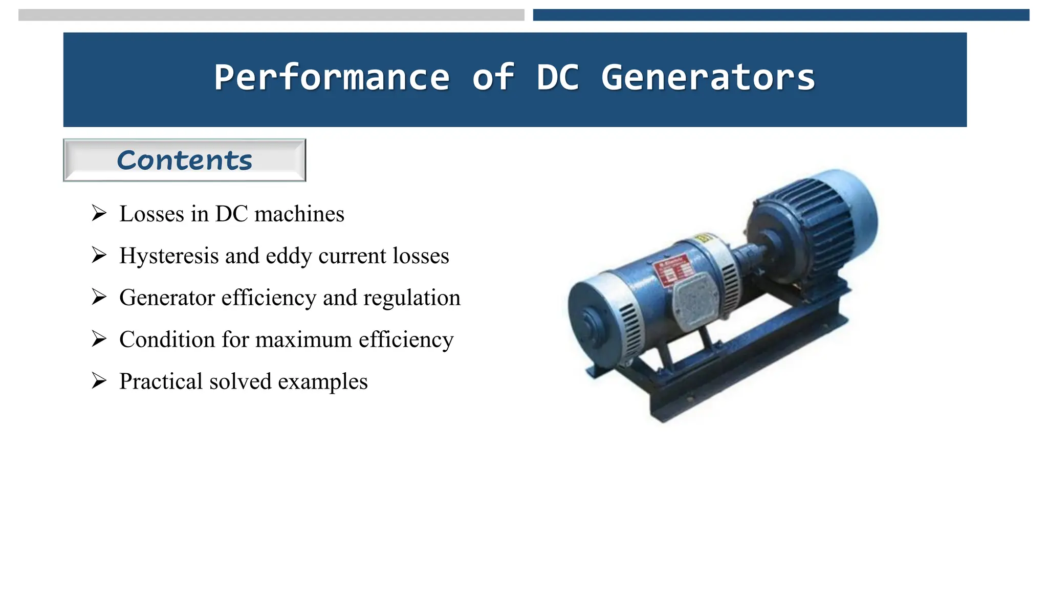
Performance of DCGenerators
Contents
➢ Losses in DC machines
➢ Hysteresis and eddy current losses
➢ Generator efficiency and regulation
➢ Condition for maximum efficiency
➢ Practical solved examples
2.
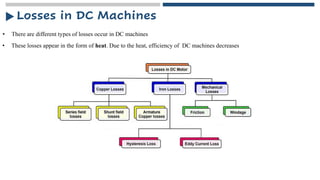
Losses in DCMachines
• There are different types of losses occur in DC machines
• These losses appear in the form of heat. Due to the heat, efficiency of DC machines decreases
3.
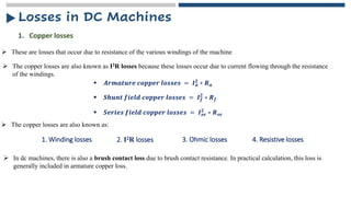
➢ These arelosses that occur due to resistance of the various windings of the machine
1. Copper losses
➢ The copper losses are also known as I2R losses because these losses occur due to current flowing through the resistance
of the windings.
▪ 𝑨𝒓𝒎𝒂𝒕𝒖𝒓𝒆 𝒄𝒐𝒑𝒑𝒆𝒓 𝒍𝒐𝒔𝒔𝒆𝒔 = 𝑰𝒂
𝟐
∗ 𝑹𝒂
▪ 𝑺𝒉𝒖𝒏𝒕 𝒇𝒊𝒆𝒍𝒅 𝒄𝒐𝒑𝒑𝒆𝒓 𝒍𝒐𝒔𝒔𝒆𝒔 = 𝑰𝒇
𝟐
∗ 𝑹𝒇
▪ 𝑺𝒆𝒓𝒊𝒆𝒔 𝒇𝒊𝒆𝒍𝒅 𝒄𝒐𝒑𝒑𝒆𝒓 𝒍𝒐𝒔𝒔𝒆𝒔 = 𝑰𝒔𝒆
𝟐 ∗ 𝑹𝒔𝒆
➢ The copper losses are also known as:
1. Winding losses 2. I2R losses 3. Ohmic losses
➢ In dc machines, there is also a brush contact loss due to brush contact resistance. In practical calculation, this loss is
generally included in armature copper loss.
4. Resistive losses
Losses in DC Machines
4.
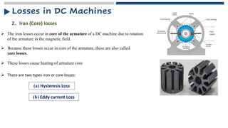
➢ The ironlosses occur in core of the armature of a DC machine due to rotation
of the armature in the magnetic field.
2. Iron (Core) losses
➢ Because these losses occur in core of the armature, these are also called
core losses.
➢ These losses cause heating of armature core
➢ There are two types iron or core losses:
(a) Hysteresis Loss
(b) Eddy current Loss
Losses in DC Machines
5.
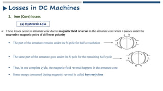
➢ These lossesoccur in armature core due to magnetic field reversal in the armature core when it passes under the
successive magnetic poles of different polarity
2. Iron (Core) losses
(a) Hysteresis Loss
▪ The part of the armature remains under the N-pole for half a revolution
▪ The same part of the armature goes under the S-pole for the remaining half cycle
▪ Thus, in one complete cycle, the magnetic field reversal happens in the armature core.
▪ Some energy consumed during magnetic reversal is called hysteresis loss
Losses in DC Machines
6.
➢ These lossesoccur in armature core due to magnetic field reversal in the armature core when it passes under the
successive magnetic poles of different polarity
2. Iron (Core) losses
(a) Hysteresis Loss
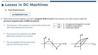
▪ The frequency of the magnetic reversal can be found by the
following mathematical expression.
𝒇 =
𝑷. 𝒏
𝟔𝟎
𝒇 = 𝒇𝒓𝒆𝒒𝒖𝒆𝒏𝒄𝒚 𝒐𝒇 𝒎𝒂𝒈𝒏𝒆𝒕𝒊𝒄 𝒓𝒗𝒆𝒓𝒔𝒂𝒍
𝑷 = 𝒏𝒖𝒎𝒃𝒆𝒓 𝒐𝒇 𝒑𝒐𝒍𝒆 𝒑𝒂𝒊𝒓𝒔
𝒏 = 𝑮𝒆𝒏𝒆𝒓𝒂𝒕𝒐𝒓 𝒔𝒑𝒆𝒆𝒅
▪ The hysteresis loss depends on the B-H
curve of the armature core material
▪ The area trapped in the hysteresis loop
represent the hysteresis losses
Losses in DC Machines
7.
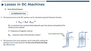
➢ The hysteresisloss in the DC machine can be calculated using the Steinmetz formula.
2. Iron (Core) losses
(a) Hysteresis Loss
➢ 𝑷𝒉𝒚𝒔 = 𝑲𝒉𝒇 𝑩𝒎𝒂𝒙
𝟏.𝟔
𝑲𝒉: is a hystersis loss constant which depends upon the volume and quality of the
armature core material
𝑭: Frequency of magnetic reversal
𝑩𝒎 : maximum value of flux density in wb/m2
➢ The hysteresis loss in dc machines can be reduced by making the
armature core of such materials that less area of hysteresis loop
like silicon steel.
Less hysteresis loss
Losses in DC Machines
8.
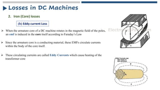
➢ When thearmature core of a DC machine rotates in the magnetic field of the poles,
an emf is induced in the core itself according to Faraday’s Law
2. Iron (Core) losses
(b) Eddy current Loss
➢ Since the armature core is a conducting material, these EMFs circulate currents
within the body of the core itself.
➢ These circulating currents are called Eddy Currents which cause heating of the
transformer core
Losses in DC Machines
9.
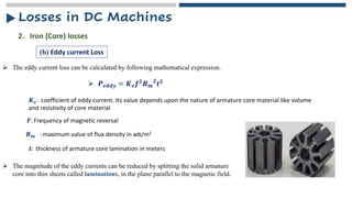
➢ The eddycurrent loss can be calculated by following mathematical expression.
2. Iron (Core) losses
(b) Eddy current Loss
➢ 𝑷𝒆𝒅𝒅𝒚 = 𝑲𝒆𝒇𝟐𝑩𝒎
𝟐
𝒕𝟐
𝑲𝒆: coefficient of eddy current. Its value depends upon the nature of armature core material like volume
and resistivity of core material
𝑭: Frequency of magnetic reversal
𝑩𝒎 : maximum value of flux density in wb/m2
𝒕: thickness of armature core lamination in meters
➢ The magnitude of the eddy currents can be reduced by splitting the solid armature
core into thin sheets called laminations, in the plane parallel to the magnetic field.
Losses in DC Machines
10.
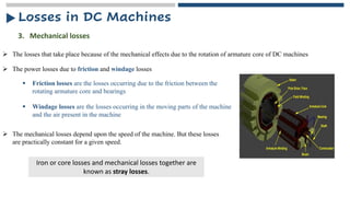
➢ The powerlosses due to friction and windage losses
3. Mechanical losses
➢ The losses that take place because of the mechanical effects due to the rotation of armature core of DC machines
▪ Windage losses are the losses occurring in the moving parts of the machine
and the air present in the machine
▪ Friction losses are the losses occurring due to the friction between the
rotating armature core and bearings
➢ The mechanical losses depend upon the speed of the machine. But these losses
are practically constant for a given speed.
Iron or core losses and mechanical losses together are
known as stray losses.
Losses in DC Machines
11.
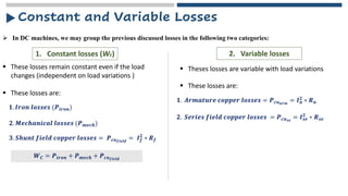
➢ In DCmachines, we may group the previous discussed losses in the following two categories:
Constant and Variable Losses
1. Constant losses (Wc) 2. Variable losses
▪ These losses remain constant even if the load
changes (independent on load variations )
▪ Theses losses are variable with load variations
▪ These losses are:
𝟏. 𝑰𝒓𝒐𝒏 𝒍𝒐𝒔𝒔𝒆𝒔 (𝑷𝒊𝒓𝒐𝒏)
𝟐. 𝑴𝒆𝒄𝒉𝒂𝒏𝒊𝒄𝒂𝒍 𝒍𝒐𝒔𝒔𝒆𝒔 (𝑷𝒎𝒆𝒄𝒉)
𝟑. 𝑺𝒉𝒖𝒏𝒕 𝒇𝒊𝒆𝒍𝒅 𝒄𝒐𝒑𝒑𝒆𝒓 𝒍𝒐𝒔𝒔𝒆𝒔 = 𝑷𝒄𝒖𝒇𝒊𝒆𝒍𝒅
= 𝑰𝒇
𝟐
∗ 𝑹𝒇
𝑾𝑪 = 𝑷𝒊𝒓𝒐𝒏 + 𝑷𝒎𝒆𝒄𝒉 + 𝑷𝒄𝒖𝒇𝒊𝒆𝒍𝒅
▪ These losses are:
𝟏. 𝑨𝒓𝒎𝒂𝒕𝒖𝒓𝒆 𝒄𝒐𝒑𝒑𝒆𝒓 𝒍𝒐𝒔𝒔𝒆𝒔 = 𝑷𝒄𝒖𝒂𝒓𝒎
= 𝑰𝒂
𝟐 ∗ 𝑹𝒂
𝟐. 𝑺𝒆𝒓𝒊𝒆𝒔 𝒇𝒊𝒆𝒍𝒅 𝒄𝒐𝒑𝒑𝒆𝒓 𝒍𝒐𝒔𝒔𝒆𝒔 = 𝑷𝒄𝒖𝒔𝒆
= 𝑰𝒔𝒆
𝟐
∗ 𝑹𝒔𝒆
12.
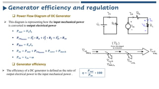
➢ This diagramis representing how the input mechanical power
is converted to output electrical power
Generator efficiency and regulation
▪ 𝑷𝒐𝒖𝒕 = 𝑽𝑳𝑰𝑳
▪ 𝑷𝒄𝒖𝒍𝒐𝒔𝒔𝒆𝒔
= 𝑰𝒂
𝟐 ∗ 𝑹𝒂 + 𝑰𝒇
𝟐
∗ 𝑹𝒇 + 𝑰𝒔𝒆
𝟐 ∗ 𝑹𝒔𝒆
▪ 𝑷𝒅𝒆𝒗 = 𝑬𝒂𝑰𝒂
▪ 𝑷𝒊𝒏 = 𝑷𝒐𝒖𝒕 + 𝑷𝒄𝒖𝒍𝒐𝒔𝒔𝒆𝒔
+ 𝑷𝒄𝒐𝒓𝒆 + 𝑷𝒎𝒆𝒄𝒉
❑ Power Flow Diagram of DC Generator
❑ Generator efficiency
▪ 𝑷𝒊𝒏 = 𝝉𝒊𝒏 ∗ 𝝎
➢ The efficiency of a DC generator is defined as the ratio of
output electrical power to the input mechanical power . ƞ =
𝑷𝒐𝒖𝒕
𝑷𝒊𝒏
∗ 𝟏𝟎𝟎
13.
Generator efficiency andregulation
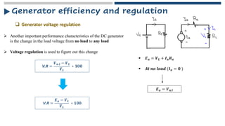
❑ Generator voltage regulation
➢ Another important performance characteristics of the DC generator
is the change in the load voltage from no load to any load
➢ Voltage regulation is used to figure out this change
V.R =
𝑽𝒏.𝒍 − 𝑽𝑳
𝑽𝑳
∗ 𝟏𝟎𝟎
▪ 𝑬𝒂 = 𝑽𝑳 + 𝑰𝒂𝑹𝒂
▪ 𝑨𝒕 𝒏𝒐 𝒍𝒐𝒂𝒅 (𝑰𝒂 = 𝟎 )
𝑬𝒂 = 𝑽𝒏.𝒍
V.R =
𝑬𝒂 − 𝑽𝑳
𝑽𝑳
∗ 𝟏𝟎𝟎
14.
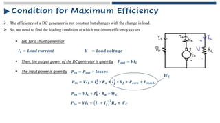
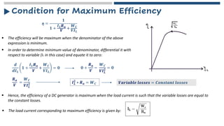
Condition for MaximumEfficiency
➢ The efficiency of a DC generator is not constant but changes with the change in load.
▪ Let, for a shunt generator
➢ So, we need to find the loading condition at which maximum efficiency occurs
𝑰𝑳 = 𝑳𝒐𝒂𝒅 𝒄𝒖𝒓𝒓𝒆𝒏𝒕 𝑽 = 𝑳𝒐𝒂𝒅 𝒗𝒐𝒍𝒕𝒂𝒈𝒆
▪ Then, the output power of the DC generator is given by 𝑷𝒐𝒖𝒕 = 𝑽𝑰𝑳
▪ The input power is given by 𝑷𝒊𝒏 = 𝑷𝒐𝒖𝒕 + 𝒍𝒐𝒔𝒔𝒆𝒔
𝑷𝒊𝒏 = 𝑽𝑰𝑳 + 𝑰𝒂
𝟐
∗ 𝑹𝒂 + 𝑰𝒇
𝟐
∗ 𝑹𝒇 + 𝑷𝒄𝒐𝒓𝒆 + 𝑷𝒎𝒆𝒄𝒉
𝑾𝑪
𝑷𝒊𝒏 = 𝑽𝑰𝑳 + 𝑰𝒂
𝟐 ∗ 𝑹𝒂 + 𝑾𝑪
𝑷𝒊𝒏 = 𝑽𝑰𝑳 + 𝑰𝑳 + 𝑰𝒇
𝟐
𝑹𝒂 + 𝑾𝑪
15.
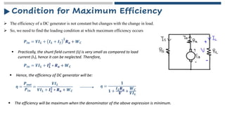
Condition for MaximumEfficiency
➢ The efficiency of a DC generator is not constant but changes with the change in load.
➢ So, we need to find the loading condition at which maximum efficiency occurs
𝑷𝒊𝒏 = 𝑽𝑰𝑳 + 𝑰𝑳 + 𝑰𝒇
𝟐
𝑹𝒂 + 𝑾𝑪
▪ Practically, the shunt field current (If) is very small as compared to load
current (IL), hence it can be neglected. Therefore,
𝑷𝒊𝒏 = 𝑽𝑰𝑳 + 𝑰𝑳
𝟐
∗ 𝑹𝒂 + 𝑾𝑪
▪ Hence, the efficiency of DC generator will be:
ƞ =
𝑷𝒐𝒖𝒕
𝑷𝒊𝒏
=
𝑽𝑰𝑳
𝑽𝑰𝑳 + 𝑰𝑳
𝟐
∗ 𝑹𝒂 + 𝑾𝑪
ƞ =
𝟏
𝟏 +
𝑰𝑳𝑹𝒂
𝑽
+
𝑾𝑪
𝑽𝑰𝑳
▪ The efficiency will be maximum when the denominator of the above expression is minimum.
16.
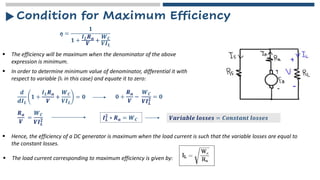
Condition for MaximumEfficiency
ƞ =
𝟏
𝟏 +
𝑰𝑳𝑹𝒂
𝑽
+
𝑾𝑪
𝑽𝑰𝑳
▪ The efficiency will be maximum when the denominator of the above
expression is minimum.
▪ In order to determine minimum value of denominator, differential it with
respect to variable (IL in this case) and equate it to zero:
𝒅
𝒅𝑰𝑳
𝟏 +
𝑰𝑳𝑹𝒂
𝑽
+
𝑾𝑪
𝑽𝑰𝑳
= 𝟎 𝟎 +
𝑹𝒂
𝑽
−
𝑾𝑪
𝑽𝑰𝑳
𝟐 = 𝟎
𝑹𝒂
𝑽
=
𝑾𝑪
𝑽𝑰𝑳
𝟐 𝑰𝑳
𝟐
∗ 𝑹𝒂 = 𝑾𝑪 𝑽𝒂𝒓𝒊𝒂𝒃𝒍𝒆 𝒍𝒐𝒔𝒔𝒆𝒔 = 𝑪𝒐𝒏𝒔𝒕𝒂𝒏𝒕 𝒍𝒐𝒔𝒔𝒆𝒔
▪ Hence, the efficiency of a DC generator is maximum when the load current is such that the variable losses are equal to
the constant losses.
▪ The load current corresponding to maximum efficiency is given by:
17.
Condition for MaximumEfficiency
ƞ =
𝟏
𝟏 +
𝑰𝑳𝑹𝒂
𝑽
+
𝑾𝑪
𝑽𝑰𝑳
▪ The efficiency will be maximum when the denominator of the above
expression is minimum.
▪ In order to determine minimum value of denominator, differential it with
respect to variable (IL in this case) and equate it to zero:
𝒅
𝒅𝑰𝑳
𝟏 +
𝑰𝑳𝑹𝒂
𝑽
+
𝑾𝑪
𝑽𝑰𝑳
= 𝟎 𝟎 +
𝑹𝒂
𝑽
−
𝑾𝑪
𝑽𝑰𝑳
𝟐 = 𝟎
𝑹𝒂
𝑽
=
𝑾𝑪
𝑽𝑰𝑳
𝟐 𝑰𝑳
𝟐
∗ 𝑹𝒂 = 𝑾𝑪 𝑽𝒂𝒓𝒊𝒂𝒃𝒍𝒆 𝒍𝒐𝒔𝒔𝒆𝒔 = 𝑪𝒐𝒏𝒔𝒕𝒂𝒏𝒕 𝒍𝒐𝒔𝒔𝒆𝒔
▪ Hence, the efficiency of a DC generator is maximum when the load current is such that the variable losses are equal to
the constant losses.
▪ The load current corresponding to maximum efficiency is given by:
18.
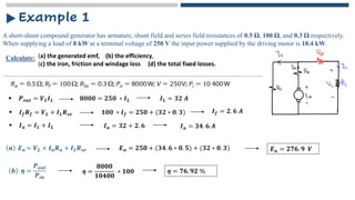
A short-shunt compoundgenerator has armature, shunt field and series field resistances of 0.5 Ω, 100 Ω, and 0.3 Ω respectively.
When supplying a load of 8 kW at a terminal voltage of 250 V the input power supplied by the driving motor is 10.4 kW.
Example 1
Calculate: (a) the generated emf, (b) the efficiency,
(c) the iron, friction and windage loss (d) the total fixed losses.
▪ 𝑷𝒐𝒖𝒕 = 𝑽𝑳𝑰𝑳 𝟖𝟎𝟎𝟎 = 𝟐𝟓𝟎 ∗ 𝑰𝑳 𝑰𝑳 = 𝟑𝟐 𝑨
▪ 𝑰𝒇𝑹𝒇 = 𝑽𝑳 + 𝑰𝑳𝑹𝒔𝒆 𝟏𝟎𝟎 ∗ 𝑰𝒇 = 𝟐𝟓𝟎 + (𝟑𝟐 ∗ 𝟎. 𝟑) 𝑰𝒇 = 𝟐. 𝟔 𝑨
𝒂 𝑬𝒂 = 𝑽𝑳 + 𝑰𝒂𝑹𝒂 + 𝑰𝑳𝑹𝒔𝒆 𝑬𝒂 = 𝟐𝟓𝟎 + (𝟑𝟒. 𝟔 ∗ 𝟎. 𝟓) + (𝟑𝟐 ∗ 𝟎. 𝟑)
▪ 𝑰𝒂 = 𝑰𝑳 + 𝑰𝑳 𝑰𝒂 = 𝟑𝟐 + 𝟐. 𝟔 𝑰𝒂 = 𝟑𝟒. 𝟔 𝑨
𝑬𝒂 = 𝟐𝟕𝟔. 𝟗 𝑽
𝒃 ƞ =
𝑷𝒐𝒖𝒕
𝑷𝒊𝒏
ƞ =
𝟖𝟎𝟎𝟎
𝟏𝟎𝟒𝟎𝟎
∗ 𝟏𝟎𝟎 ƞ = 𝟕𝟔. 𝟗𝟐 %
19.
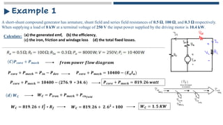
A short-shunt compoundgenerator has armature, shunt field and series field resistances of 0.5 Ω, 100 Ω, and 0.3 Ω respectively.
When supplying a load of 8 kW at a terminal voltage of 250 V the input power supplied by the driving motor is 10.4 kW.
Example 1
Calculate: (a) the generated emf, (b) the efficiency,
(c) the iron, friction and windage loss (d) the total fixed losses.
𝑪 𝑷𝒄𝒐𝒓𝒆 + 𝑷𝒎𝒆𝒄𝒉 𝒇𝒓𝒐𝒎 𝒑𝒐𝒘𝒆𝒓 𝒇𝒍𝒐𝒘 𝒅𝒊𝒂𝒈𝒓𝒂𝒎
𝑷𝒄𝒐𝒓𝒆 + 𝑷𝒎𝒆𝒄𝒉 = 𝑷𝒊𝒏 − 𝑷𝒅𝒆𝒗 𝑷𝒄𝒐𝒓𝒆 + 𝑷𝒎𝒆𝒄𝒉 = 𝟏𝟎𝟒𝟎𝟎 − (𝑬𝒂𝑰𝒂)
𝑷𝒄𝒐𝒓𝒆 + 𝑷𝒎𝒆𝒄𝒉 = 𝟏𝟎𝟒𝟎𝟎 − (𝟐𝟕𝟔. 𝟗 ∗ 𝟑𝟒. 𝟔) 𝑷𝒄𝒐𝒓𝒆 + 𝑷𝒎𝒆𝒄𝒉 = 𝟖𝟏𝟗. 𝟐𝟔 𝒘𝒂𝒕𝒕
𝒅 𝑾𝑪 𝑾𝑪 = 𝑷𝒊𝒓𝒐𝒏 + 𝑷𝒎𝒆𝒄𝒉 + 𝑷𝒄𝒖𝒇𝒊𝒆𝒍𝒅
𝑾𝑪 = 𝟖𝟏𝟗. 𝟐𝟔 + 𝑰𝒇
𝟐
∗ 𝑹𝒇 𝑾𝑪 = 𝟖𝟏𝟗. 𝟐𝟔 + 𝟐. 𝟔𝟐
∗ 𝟏𝟎𝟎 𝑾𝑪 = 𝟏. 𝟓 𝑲𝑾
20.
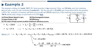
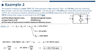
The armature windingof a 4-pole, 220 V DC shunt generator is lap connected. There are 120 slots, each slot containing
two coil sides, each coil side containing 5 conductors. The flux per pole is 25 mWb and current delivered by the generator
is 27 A. The resistance of armature and field circuit are 0.1 and 125 Ω respectively. If the rotational losses amount to be
780 W and the drop voltage on each brush to be 1.5 V find:
Example 2
(a) Prime Mover Speed in rpm, (b) Electromagnetic torque,
(c) Input Power in HP (d) Efficiency.
(e) The value of load current at which maximum efficiency occurs.
▪ 𝑽𝑳 = 𝟐𝟐𝟎 𝑽 ▪ 𝑰𝒇 =
𝑽𝑳
𝑹𝒇
=
𝟐𝟐𝟎
𝟏𝟐𝟓
= 𝟏. 𝟕𝟔 𝑨
𝒂 𝒏 = ? ? 𝑬𝒂 = 𝑲𝒂 ∗ ∅ ∗ 𝝎
▪ 𝑰𝑳 = 𝟐𝟕 𝑨 ▪ 𝑰𝒂 = 𝑰𝑳 + 𝑰𝑳 = 𝟏. 𝟕𝟔 + 𝟐𝟕 = 𝟐𝟖. 𝟕𝟔𝑨
𝑬𝒂 = 𝑽𝑳 + 𝑰𝒂𝑹𝒂 + 𝑽𝒃𝒓𝒖𝒔𝒉𝒆𝒔 = 𝟐𝟐𝟎 + 𝟐𝟖. 𝟕𝟔 ∗ 𝟎. 𝟏 + 𝟏. 𝟓 ∗ 𝟐 = 𝟐𝟐𝟓. 𝟖𝟕𝟔 𝑽
∅ = 𝟐𝟓 𝒎 𝑾𝒃
𝑲𝒂 =
𝒁 ∗ 𝟐𝑷
𝟐𝝅𝒂
=
(𝟏𝟐𝟎 ∗ 𝟐 ∗ 𝟓) ∗ 𝟒
𝟐𝝅 ∗ 𝟒
= 𝟏𝟗𝟎. 𝟗𝟖𝟓𝟗
21.
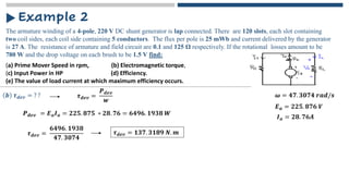
The armature windingof a 4-pole, 220 V DC shunt generator is lap connected. There are 120 slots, each slot containing
two coil sides, each coil side containing 5 conductors. The flux per pole is 25 mWb and current delivered by the generator
is 27 A. The resistance of armature and field circuit are 0.1 and 125 Ω respectively. If the rotational losses amount to be
780 W and the drop voltage on each brush to be 1.5 V find:
Example 2
𝒂 𝒏 = ? ? 𝑬𝒂 = 𝑲𝒂 ∗ ∅ ∗ 𝝎 𝑬𝒂 = 𝟐𝟐𝟓. 𝟖𝟕𝟔 𝑽
∅ = 𝟐𝟓 𝒎 𝑾𝒃
𝑲𝒂 = 𝟏𝟗𝟎. 𝟗𝟖𝟓𝟗
𝟐𝟐𝟓. 𝟖𝟕𝟔 = 𝟏𝟗𝟎. 𝟗𝟖𝟓𝟗 ∗ 𝟐𝟓 ∗ 𝟏𝟎−𝟑 ∗ 𝝎 𝝎 = 𝟒𝟕. 𝟑𝟎𝟕𝟒 𝒓𝒂𝒅/𝒔
𝝎 =
𝟐𝝅𝒏
𝟔𝟎
𝟒𝟕. 𝟑𝟎𝟕𝟒 =
𝟐𝝅𝒏
𝟔𝟎 𝒏 = 𝟒𝟓𝟏. 𝟕𝟓𝟐 𝒓𝒑𝒎
(a) Prime Mover Speed in rpm, (b) Electromagnetic torque,
(c) Input Power in HP (d) Efficiency.
(e) The value of load current at which maximum efficiency occurs.
22.
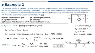
The armature windingof a 4-pole, 220 V DC shunt generator is lap connected. There are 120 slots, each slot containing
two coil sides, each coil side containing 5 conductors. The flux per pole is 25 mWb and current delivered by the generator
is 27 A. The resistance of armature and field circuit are 0.1 and 125 Ω respectively. If the rotational losses amount to be
780 W and the drop voltage on each brush to be 1.5 V find:
Example 2
𝒃 𝝉𝒅𝒆𝒗 = ? ? 𝝎 = 𝟒𝟕. 𝟑𝟎𝟕𝟒 𝒓𝒂𝒅/𝒔
𝝉𝒅𝒆𝒗 =
𝑷𝒅𝒆𝒗
𝒘
𝑷𝒅𝒆𝒗 = 𝑬𝒂𝑰𝒂 = 𝟐𝟐𝟓. 𝟖𝟕𝟓 ∗ 𝟐𝟖. 𝟕𝟔 = 𝟔𝟒𝟗𝟔. 𝟏𝟗𝟑𝟖 𝑾
𝑬𝒂 = 𝟐𝟐𝟓. 𝟖𝟕𝟔 𝑽
𝑰𝒂 = 𝟐𝟖. 𝟕𝟔𝑨
𝝉𝒅𝒆𝒗 =
𝟔𝟒𝟗𝟔. 𝟏𝟗𝟑𝟖
𝟒𝟕. 𝟑𝟎𝟕𝟒
𝝉𝒅𝒆𝒗 = 𝟏𝟑𝟕. 𝟑𝟏𝟖𝟗 𝑵. 𝒎
(a) Prime Mover Speed in rpm, (b) Electromagnetic torque,
(c) Input Power in HP (d) Efficiency.
(e) The value of load current at which maximum efficiency occurs.
23.
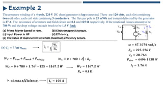
The armature windingof a 4-pole, 220 V DC shunt generator is lap connected. There are 120 slots, each slot containing
two coil sides, each coil side containing 5 conductors. The flux per pole is 25 mWb and current delivered by the generator
is 27 A. The resistance of armature and field circuit are 0.1 and 125 Ω respectively. If the rotational losses amount to be
780 W and the drop voltage on each brush to be 1.5 V find:
Example 2
𝑪 𝑷𝒊𝒏 = ? ? 𝝎 = 𝟒𝟕. 𝟑𝟎𝟕𝟒 𝒓𝒂𝒅/𝒔
𝑬𝒂 = 𝟐𝟐𝟓. 𝟖𝟕𝟔 𝑽
𝑰𝒂 = 𝟐𝟖. 𝟕𝟔𝑨
𝑷𝒅𝒆𝒗 = 𝟔𝟒𝟗𝟔. 𝟏𝟗𝟑𝟖 𝑾
𝒇𝒓𝒐𝒎 𝒑𝒐𝒘𝒆𝒓 𝒇𝒍𝒐𝒘 𝒅𝒊𝒂𝒈𝒓𝒂𝒎
𝑷𝒊𝒏 = 𝑷𝒅𝒆𝒗 + 𝑷𝒄𝒐𝒓𝒆 + 𝑷𝒎𝒆𝒄𝒉
𝑷𝒊𝒏 = 𝟔𝟒𝟗𝟔. 𝟏𝟗𝟑𝟖 + 𝟎 𝒏𝒆𝒈𝒍𝒆𝒄𝒕𝒆𝒅 + 𝟕𝟖𝟎 𝑷𝒊𝒏 = 𝟕𝟐𝟕𝟔. 𝟏𝟗𝟑𝟖 𝑾
𝑰 𝑯𝑷 = 𝟕𝟒𝟔 𝑾 𝑷𝒊𝒏 =
𝟕𝟐𝟕𝟔. 𝟏𝟗𝟑𝟖
𝟕𝟒𝟔
𝑷𝒊𝒏 = 𝟗. 𝟕𝟓𝟑𝟔 𝑯𝑷
𝒅 ƞ = ? ? ƞ =
𝑷𝒐𝒖𝒕
𝑷𝒊𝒏
=
𝑽𝑳𝑰𝑳
𝟕𝟐𝟕𝟔. 𝟏𝟗𝟑𝟖
=
𝟐𝟕 ∗ 𝟐𝟐𝟎
𝟕𝟐𝟕𝟔. 𝟏𝟗𝟑𝟖 ƞ = 𝟖𝟏. 𝟔%
(a) Prime Mover Speed in rpm, (b) Electromagnetic torque,
(c) Input Power in HP (d) Efficiency.
(e) The value of load current at which maximum efficiency occurs.
24.
The armature windingof a 4-pole, 220 V DC shunt generator is lap connected. There are 120 slots, each slot containing
two coil sides, each coil side containing 5 conductors. The flux per pole is 25 mWb and current delivered by the generator
is 27 A. The resistance of armature and field circuit are 0.1 and 125 Ω respectively. If the rotational losses amount to be
780 W and the drop voltage on each brush to be 1.5 V find:
Example 2
𝒆 𝑰𝑳 = ? ? 𝒂𝒕 ƞ𝒎𝒂𝒙
𝝎 = 𝟒𝟕. 𝟑𝟎𝟕𝟒 𝒓𝒂𝒅/𝒔
𝑬𝒂 = 𝟐𝟐𝟓. 𝟖𝟕𝟔 𝑽
𝑰𝒂 = 𝟐𝟖. 𝟕𝟔𝑨
𝑷𝒅𝒆𝒗 = 𝟔𝟒𝟗𝟔. 𝟏𝟗𝟑𝟖 𝑾
(a) Prime Mover Speed in rpm, (b) Electromagnetic torque,
(c) Input Power in HP (d) Efficiency.
(e) The value of load current at which maximum efficiency occurs.
𝑾𝑪 = 𝟎 + 𝟕𝟖𝟎 + 𝑰𝒇
𝟐
∗ 𝑹𝒇
𝑾𝑪 = 𝑷𝒊𝒓𝒐𝒏 + 𝑷𝒎𝒆𝒄𝒉 + 𝑷𝒄𝒖𝒇𝒊𝒆𝒍𝒅
𝑰𝒇 = 𝟏. 𝟕𝟔 𝑨
𝑾𝑪 = 𝟎 + 𝟕𝟖𝟎 + 𝟏. 𝟕𝟔𝟐
∗ 𝟏𝟐𝟓 = 𝟏𝟏𝟔𝟕. 𝟐 𝑾 𝑾𝑪 = 𝟏𝟏𝟔𝟕. 𝟐 𝑾
𝑹𝒂 = 0.1 Ω
➢ 𝒂𝒕 𝒎𝒂𝒙 𝒆𝒇𝒇𝒊𝒄𝒊𝒆𝒏𝒄𝒚 𝑰𝑳 = 𝟏𝟎𝟖 𝑨
25.
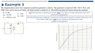
The magnetization curvefor a separate excited dc generator is shown. The generator is rated at 6 kW, 120 V, 50 A, and
1800 r/min and is shown in Figure. Its field current is rated at 5 A. The following data are known about the machine
Example 3
(a) If this generator is operating at no load, what is the range of voltage adjustments that can be
achieved by changing Radj?
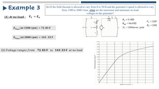
(b) If the field rheostat is allowed to vary from 0 to 30 Ω and the generator’s speed is allowed to vary
from 1500 to 2000 r/min, what are the maximum and minimum no-load
voltages in the generator?
26.
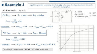
𝒂 𝑨𝒕 𝒏𝒐𝒍𝒐𝒂𝒅 ∶
Example 3 (a) If this generator is operating at no load, what is the range of voltage adjustments that can be
achieved by changing Radj?
𝑽𝑳 = 𝑬𝒂
𝑭𝒐𝒓 𝑬𝒂𝒎𝒂𝒙 𝑹𝒂𝒅𝒋 = 𝟎 𝒐𝒉𝒎
𝑰𝒇 = 𝒎𝒂𝒙
𝑰𝒇𝒎𝒂𝒙 =
𝟏𝟐𝟎
𝟐𝟒 + 𝟎
= 𝟓𝑨
𝑭𝒓𝒐𝒎 𝑶𝑪𝑪 𝒂𝒕 𝑰𝒇𝒎𝒂𝒙 = 𝟓𝑨 𝑬𝒂𝒎𝒂𝒙
= 𝑽𝑳𝒎𝒂𝒙
= 𝟏𝟐𝟗 𝑽
𝑭𝒐𝒓 𝑬𝒎𝒊𝒏 𝑹𝒂𝒅𝒋 = 𝟑𝟎 𝒐𝒉𝒎𝒔
𝑰𝒇 = 𝒎𝒊𝒏
𝑰𝒇𝒎𝒊𝒏 =
𝟏𝟐𝟎
𝟐𝟒 + 𝟑𝟎
= 𝟐. 𝟐𝟐𝑨
𝑭𝒓𝒐𝒎 𝑶𝑪𝑪 𝒂𝒕 𝑰𝒇𝒎𝒂𝒙 = 𝟐. 𝟐𝟐𝑨 𝑬𝒂𝒎𝒊𝒏
= 𝑽𝒎𝒊𝒏 = 𝟖𝟕. 𝟒 𝑽
𝑎 𝑉𝑜𝑙𝑡𝑎𝑔𝑒 𝑟𝑎𝑛𝑔𝑒𝑠 𝑓𝑟𝑜𝑚 𝟖𝟕. 𝟒 𝑽 𝑡𝑜 𝟏𝟐𝟗 𝑽 𝑎𝑡 𝑛𝑜 𝑙𝑜𝑎𝑑
27.
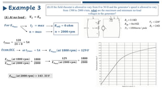
𝒃 𝑨𝒕 𝒏𝒐𝒍𝒐𝒂𝒅 ∶
Example 3
𝑽𝑳 = 𝑬𝒂
𝑭𝒐𝒓 𝑬𝒂𝒎𝒂𝒙 𝑹𝒂𝒅𝒋 = 𝟎 𝒐𝒉𝒎
𝑰𝒇 = 𝒎𝒂𝒙
(b) If the field rheostat is allowed to vary from 0 to 30 Ω and the generator’s speed is allowed to vary
from 1500 to 2000 r/min, what are the maximum and minimum no-load
voltages in the generator?
𝒏 = 𝒎𝒂𝒙 𝒏 = 𝟐𝟎𝟎𝟎 𝒓𝒑𝒎
𝑰𝒇𝒎𝒂𝒙 =
𝟏𝟐𝟎
𝟐𝟒 + 𝟎
= 𝟓𝑨
𝑭𝒓𝒐𝒎 𝑶𝑪𝑪 𝒂𝒕 𝑰𝒇𝒎𝒂𝒙 = 𝟓𝑨 𝑬𝒂𝒎𝒂𝒙
𝒂𝒕 𝟏𝟖𝟎𝟎 𝒓𝒑𝒎 = 𝟏𝟐𝟗 𝑽
𝑬𝒂𝒎𝒂𝒙
𝒂𝒕 𝟏𝟖𝟎𝟎 𝒓𝒑𝒎
𝑬𝒂𝒎𝒂𝒙
𝒂𝒕 𝟐𝟎𝟎𝟎 𝒓𝒑𝒎
=
𝟏𝟖𝟎𝟎
𝟐𝟎𝟎𝟎
𝟏𝟐𝟗
𝑬𝒂𝒎𝒂𝒙
𝒂𝒕 𝟐𝟎𝟎𝟎 𝒓𝒑𝒎
=
𝟏𝟖𝟎𝟎
𝟐𝟎𝟎𝟎
𝑬𝒂𝒎𝒂𝒙
𝒂𝒕 𝟐𝟎𝟎𝟎 𝒓𝒑𝒎 = 𝟏𝟒𝟑 . 𝟑𝟑 𝑽
28.
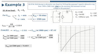
𝒃 𝑨𝒕 𝒏𝒐𝒍𝒐𝒂𝒅 ∶
Example 3
𝑽𝑳 = 𝑬𝒂
𝑭𝒐𝒓 𝑬𝒂𝒎𝒊𝒏 𝑹𝒂𝒅𝒋 = 𝟑𝟎 𝒐𝒉𝒎𝒔
𝑰𝒇 = 𝒎𝒊𝒏
(b) If the field rheostat is allowed to vary from 0 to 30 Ω and the generator’s speed is allowed to vary
from 1500 to 2000 r/min, what are the maximum and minimum no-load
voltages in the generator?
𝒏 = 𝒎𝒊𝒏 𝒏 = 𝟏𝟓𝟎𝟎 𝒓𝒑𝒎
𝑰𝒇𝒎𝒊𝒏 =
𝟏𝟐𝟎
𝟐𝟒 + 𝟑𝟎
= 𝟐. 𝟐𝟐 𝑨
𝑭𝒓𝒐𝒎 𝑶𝑪𝑪 𝒂𝒕 𝑰𝒇𝒎𝒊𝒏 = 𝟐. 𝟐𝟐𝑨 𝑬𝒂𝒎𝒊𝒏
𝒂𝒕 𝟏𝟖𝟎𝟎 𝒓𝒑𝒎 = 𝟖𝟕. 𝟒 𝑽
𝑬𝒂𝒎𝒊𝒏
𝒂𝒕 𝟏𝟖𝟎𝟎 𝒓𝒑𝒎
𝑬𝒂𝒎𝒊𝒏
𝒂𝒕 𝟏𝟓𝟎𝟎 𝒓𝒑𝒎
=
𝟏𝟖𝟎𝟎
𝟏𝟓𝟎𝟎
𝟖𝟕. 𝟒
𝑬𝒂𝒎𝒊𝒏
𝒂𝒕 𝟏𝟓𝟎𝟎 𝒓𝒑𝒎
=
𝟏𝟖𝟎𝟎
𝟏𝟓𝟎𝟎
𝑬𝒂𝒎𝒊𝒏
𝒂𝒕 𝟏𝟓𝟎𝟎 𝒓𝒑𝒎 = 𝟕𝟐. 𝟖𝟑 𝑽
29.
𝒃 𝑨𝒕 𝒏𝒐𝒍𝒐𝒂𝒅 ∶
Example 3
𝑽𝑳 = 𝑬𝒂
(b) If the field rheostat is allowed to vary from 0 to 30 Ω and the generator’s speed is allowed to vary
from 1500 to 2000 r/min, what are the maximum and minimum no-load
voltages in the generator?
𝑬𝒂𝒎𝒊𝒏
𝒂𝒕 𝟏𝟓𝟎𝟎 𝒓𝒑𝒎 = 𝟕𝟐. 𝟖𝟑 𝑽
𝑬𝒂𝒎𝒂𝒙
𝒂𝒕 𝟐𝟎𝟎𝟎 𝒓𝒑𝒎 = 𝟏𝟒𝟑 . 𝟑𝟑 𝑽
𝑏 𝑉𝑜𝑙𝑡𝑎𝑔𝑒 𝑟𝑎𝑛𝑔𝑒𝑠 𝑓𝑟𝑜𝑚 𝟕𝟐. 𝟖𝟑 𝑽 𝑡𝑜 𝟏𝟒𝟑. 𝟑𝟑 𝑽 𝑎𝑡 𝑛𝑜 𝑙𝑜𝑎𝑑