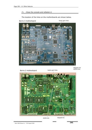
The document provides contact information for Avolites in the UK and US, as well as instructions for finding the software version and serial number on the Pearl 2004 console. It notes that the manual may not exactly match the console's operation, as Avolites has a policy of continuous improvement. The manual was written by Tim Mitchell of Sabre Technology Ltd and published in August 2004.


![1. Welcome to the Pearl - Page 3
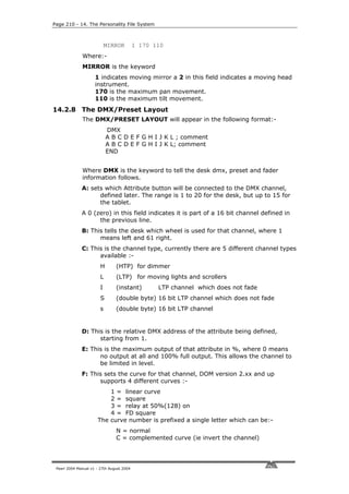
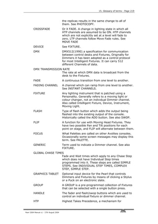
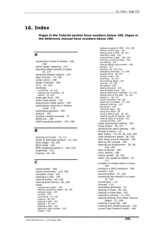
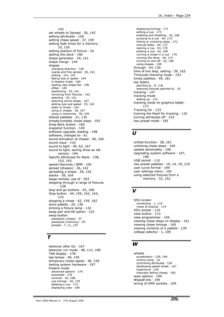
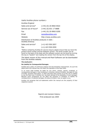
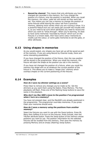
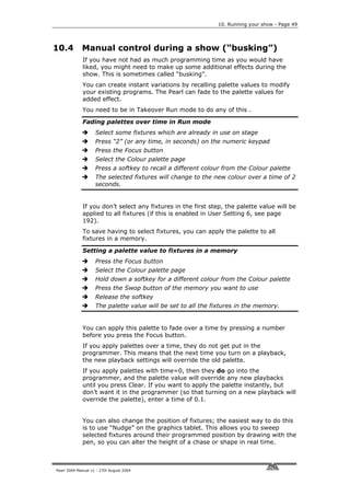
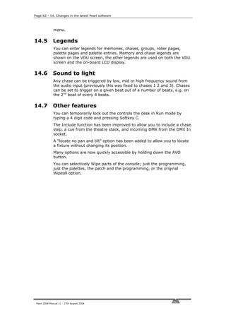
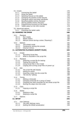
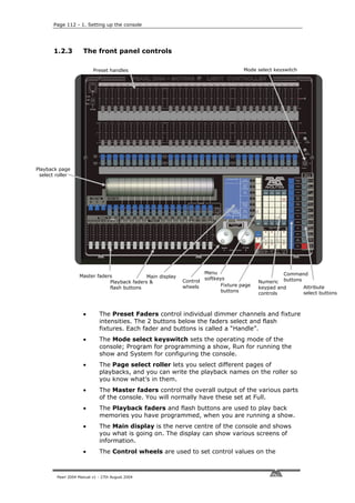
what is going on. The display can show various screens of information.
• The Control wheels are used to set control values on the fixtures,
and to set chase speeds and fades.
• The Menu softkeys (labelled A – G) are used to select control options.
The display next to the buttons shows what each one will do. The
options for each key change depending on what the console is doing.
Softkey commands are shown in the manual with square brackets like
this: A [Chase Parameters]
• The Numeric keypad and other control buttons are used to enter
values and change controls on the console.
• The Fixture Page buttons are below the keypad, which select 4 pages
for the Preset Faders.
• The blue Command buttons are used to carry out functions such as
storing memories, copying, saving to disk, etc. These buttons have
lights on to indicate when they are active.
• The Attribute select buttons are used to select which attributes of a
fixture (e.g. colour, gobo, pan, focus) are going to be controlled using
the Control wheels. The buttons have lights on to show you which
attributes are active. The bottom (red) button allows you to reduce the
intensity of a fixture if it loses position during a show.
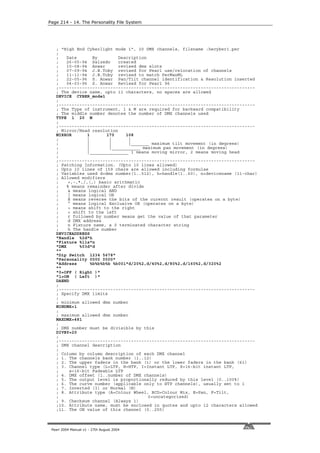
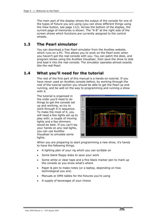
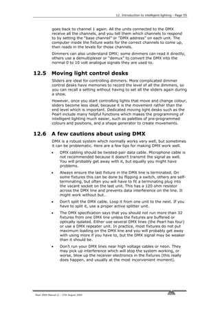
The VDU screen shows more information than the on-board displays.
It is useful when setting up the console and programming shows. When
entering text or numbers, what you are typing is shown only on the
VDU screen. If you are short of space you can often manage without it
when you are running a show.
Memory contents Today’s date and time
Fixture output values
Function of Function of
left wheel right wheel
Pearl 2004 Manual v1 - 27th August 2004](https://image.slidesharecdn.com/pearl2004man270804-100221092248-phpapp02/85/Pearl2004-Man270804-11-320.jpg)

![Page 8 - 2. Patching
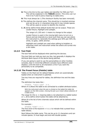
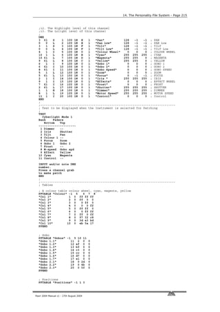
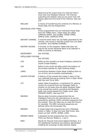
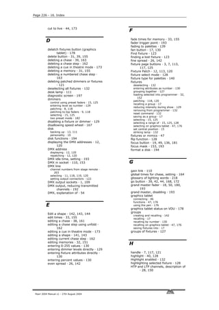
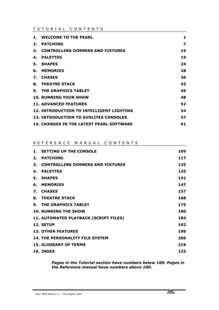
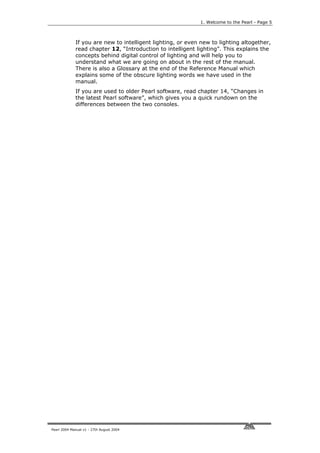
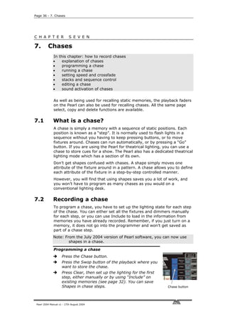
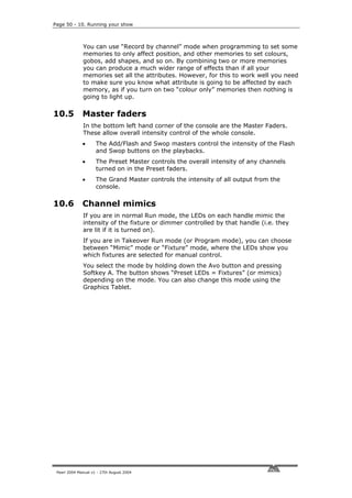
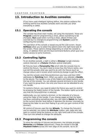
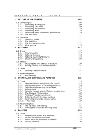
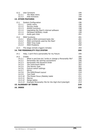
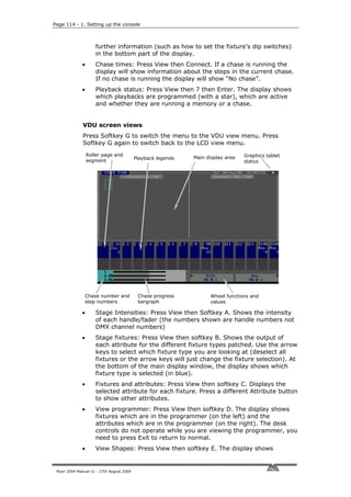
Clearing the Pearl
Turn the mode keyswitch to “System”
Select softkey A [Service]
Select softkey F [Wipe].
Press F [“Wipeall], to confirm. The
memory will be wiped.
Turn the key to “Program” to prepare
for programming.
Mode keyswitch
The Pearl is now pristine and new, with all
options set to default, and all memories empty, ready for you to start
your show.
2.2 Patching dimmers
Each dimmer channel you want to use has to be allocated to one of the
handles. Then, when you want to control the dimmer channel, you just
fade up the slider.
Patching dimmer channels
Make sure the key is set to “Program”
Press Patch (one of the blue “command” buttons).
Press A [Dimmer]
The Pearl will start at DMX address 001 (shown on
the top line of the display). If your dimmer rack is
at a different address, you can change this by
typing in the new address on the numeric keypad.
Press the blue preset “Swop” button below preset
fader number 1. The fader and flash/swop buttons
will become the “handle” used to control that
dimmer channel.
The Pearl will update the DMX address to the next
free channel, so you can just press another button
to patch the next dimmer. Swop button
Press Exit when you have finished patching.
You can now control the dimmer channel on handle 1 using the fader
(the buttons do not operate as flash buttons in Program mode, only in
Run mode).
If you have lots of dimmers to patch, there are some quicker ways. If
you just want to patch 10 dimmers in sequence on to handles 21-30,
you can do it this way:
Patching a range of dimmers to buttons
Enter Dimmer Patch mode
Enter the DMX channel you want the range to start at, if it’s
different to the one the Pearl is displaying
Hold down the Swop button of the first handle to be patched
(handle 21)
Pearl 2004 Manual v1 - 27th August 2004](https://image.slidesharecdn.com/pearl2004man270804-100221092248-phpapp02/85/Pearl2004-Man270804-16-320.jpg)
![Page 10 - 2. Patching
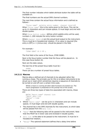
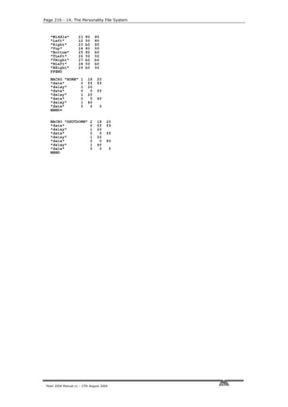
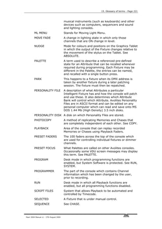
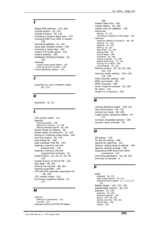
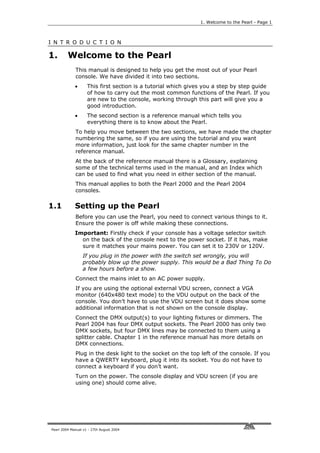
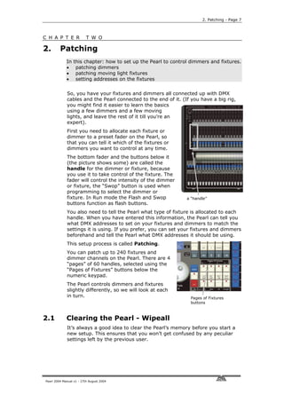
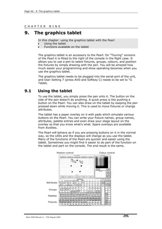
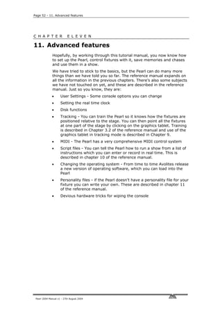
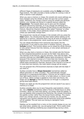
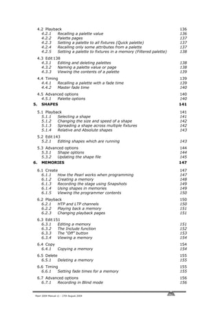
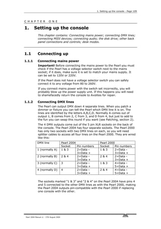
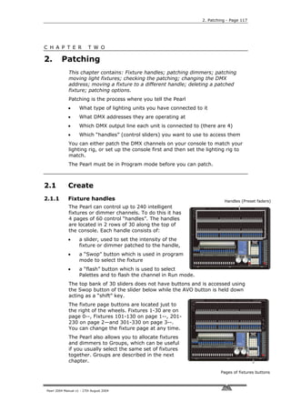
While you are in
Patch mode, the
VDU screen shows a
DMX channel grid to
tell you which
channels you have
patched so far and
which are free.
Dimmers and
fixtures are
identified by
different letters,
dimmers are always
“a”.
You can also display the patch on the LCD screen by pressing View (on
the numeric keypad) then C [DMX patch] (shows which handle each
DMX channel is allocated to) or D [Fixture patch], which shows a list in
handle order.
2.3 Patching moving light fixtures
Moving light fixtures are controlled slightly differently to dimmers; a
dimmer only has one controllable attribute, intensity. But a moving
light fixture can have many attributes, such as pan, tilt, colour, gobo
etc. When you patch a fixture, you will see on the VDU screen that it
occupies a block of DMX channels rather than just one. However, the
principle is still the same.
The Pearl has personality files for most lighting fixtures in the known
universe, and these are stored internally in the console. If you want to
use a personality not available in the console, you can load it from a
personality disk, a wide range of which can be downloaded from the
Avolites website. See section 12 in the reference manual for details of
how to download personalities.
Note: To use the internal personality files, make sure there is no disk
in the disk drive.
Patching a fixture
Make sure there is no disk in the disk drive
Press Patch
Press B [Choose a fixture]
The display will show “Please select an instrument” on the top line.
A list of known fixtures will appear next to the softkeys after a
pause.
Use Softkeys F and G to go up and down the list and find the
correct fixture, then press the Softkey next to the fixture to select
it.
The Pearl will load the fixture information (this may take a few
seconds). The display shows information about the fixture.
The Pearl will ask “Use preset palettes?”.
Press A [Yes]. (This is explained later)
The Pearl will offer you the first free DMX address (on the top line
of the display). You can change this using the numeric keypad if
you want the fixture at a different address.
Pearl 2004 Manual v1 - 27th August 2004](https://image.slidesharecdn.com/pearl2004man270804-100221092248-phpapp02/85/Pearl2004-Man270804-18-320.jpg)
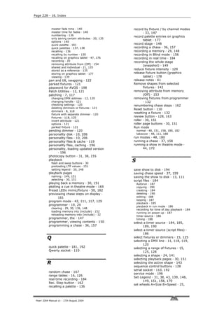
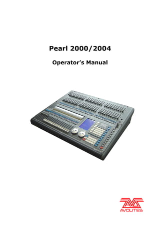
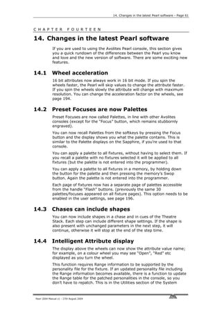
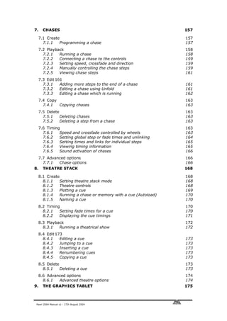
![2. Patching - Page 11
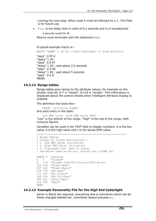
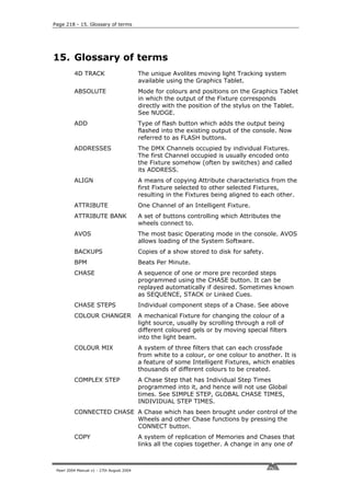
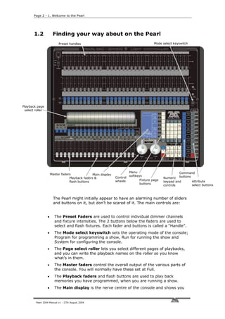
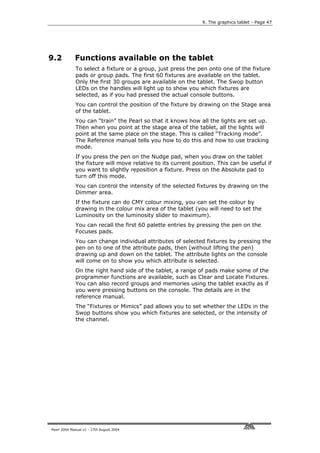
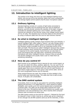
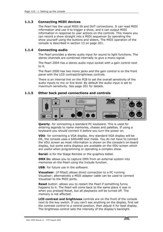
Press the Swop button on handle 11 to patch the fixture you have
selected to handle 11.
The display will show the block of channels occupied by the fixture.
Patch more fixtures, or press Exit when you have finished.
You can continue to patch this type of fixture at the next free DMX
address by pressing the next Swop button you want to use. You can
also patch a range of fixtures by holding down the first button in the
range and pressing the last button, as with dimmers.
You can patch fixtures to the top faders by holding down the AVO
button, but if you do this you will need to hold down the AVO button to
select them when programming as well, so it’s easiest to only patch
dimmers to the top faders as you can control dimmers just with the
fader.
If you want to patch a different type of fixture, you can change the type
of fixture to be patched very easily.
To change the fixture type
Press A [Select another fixture]
Choose the fixture type from the list on the softkeys
Patch as before
Note: The “preset palettes” contain 9 position, 10 colour and 10 gobo
settings. You can call back these settings instantly from the
palette buttons when you are programming. This allows you to
select, for example, “Yellow” or “Blue” instead of setting up the
value using the wheels. You can only load the preset palettes
during patching.
The Pearl has four physical DMX output lines, identified as A, B, C, D.
You can patch onto any of the four lines using E [Select a DMX line].
However, to keep it simple, stick to line A while you are learning.
2.4 Labelling the console
It’s a good idea to stick a strip of tape above the handle Swop buttons,
and write on it what is patched on each handle, such as “Mac SL”, “Mac
Centre” etc. This will help you greatly when programming as you try
and remember where you patched everything.
2.5 Addressing lights to match the Pearl
When you are patching, it’s easiest to let the Pearl allocate all the DMX
addresses, then go round to the actual dimmers and fixtures and set
the addresses to match the Pearl’s settings. This makes sure that there
are no overlaps or gaps in the DMX addresses.
You can also work out the DMX map yourself and tell the Pearl what
DMX channels to use while you’re patching, but then you need to make
sure yourself that nothing overlaps.
The Pearl can tell you the DMX address it is using for each fixture, and
in some cases can show you how to set the dip switches on the fixture.
Write down the addresses for all the fixtures, then go and set them.
Pearl 2004 Manual v1 - 27th August 2004](https://image.slidesharecdn.com/pearl2004man270804-100221092248-phpapp02/85/Pearl2004-Man270804-19-320.jpg)
![Page 12 - 2. Patching
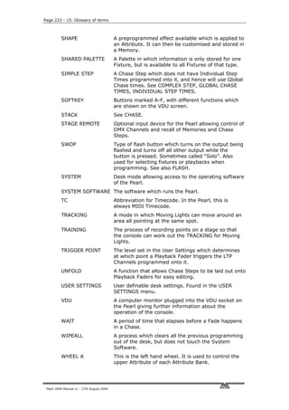
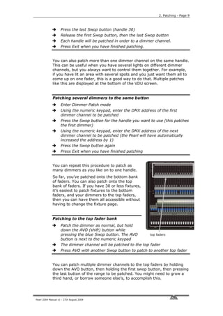
Displaying the DMX address for fixtures
Press the View button (next to the
numeric keys)
Press D [Fixture Patch]
The display will show a list of the
handles to which you have patched
fixtures or dimmers, with the DMX line
and address (e.g. A24 is address 24 on
DMX line A).
One handle on the list has an arrow next
to it. In the lower part of the screen,
more information is shown for this
fixture.
Use the Arrow keys to move the arrow
up and down the list, and show
information for the other fixtures in the
list.
You can also press View then C [DMX Patch] to display a list of
DMX channels and which fixture is patched at that address.
2.6 Changing what you have done
If you need to change the patching you have done, it’s possible to re-
patch a fixture to a different DMX address using the Repatch Fixtures
softkey. You can also move a fixture onto a different handle, and delete
a fixture from a handle, but this loses any programming for the fixture.
How to change the patching is described in detail in section 2 of the
reference manual on page 120.
2.7 Patch Utilities
You can invert the operation of channels and set various other fixture-
specific options using the Patch Utilities softkey. Inverting pan and tilt
channels can be useful to mirror fixtures on opposite sides of the stage,
or to correct for hanging a fixture the wrong way round. Section 2 of
the reference manual on page 121 describes how to set these options.
2.8 Completing the patch
When you have patched all your dimmers and fixtures, press the Exit
button on the numeric keypad to go back to normal mode. You have
now completed the setting up of the lighting system, and it’s time to
get to work on programming a show. But there’s one important thing to
do first…
2.9 Saving the contents of the Pearl to disk
The Pearl has a built in floppy disk drive which allows you to save
everything you have done. You should get into the habit of saving your
show regularly to guard against that unexpected moment when the
worst happens.
Pearl 2004 Manual v1 - 27th August 2004](https://image.slidesharecdn.com/pearl2004man270804-100221092248-phpapp02/85/Pearl2004-Man270804-20-320.jpg)
![2. Patching - Page 13
The disk drive is in the front left hand corner of the console, beneath
the master faders. If you’re using the
console in its flightcase, you might need to
lift it slightly to access the disk drive.
It only takes a minute or so to save the
contents of the Pearl to disk. You can then
reload it if you mess up the show by
accidentally changing something, or if some
helpful person steals the Pearl you can load
your programming into a replacement
Disk button
console and the show can go on.
Backing up the Pearl to disk
Press the Disk button in the bottom right hand corner of the Pearl
Insert a blank formatted 1.44MB disk into the disk drive (anything
on the disk will be wiped).
Select B [Save show to disk].
The Pearl will ask for a filename for the show. Type this on the
QWERTY keyboard then press Enter. If you don’t have a keyboard
connected you can just accept the default showname by pressing
Enter.
The Pearl will ask if you want to make the show compatible with
Sep 2000 software. Press B [No].
The Pearl will save your current show onto the disk. The display will
tell you when the Pearl has finished.
The Pearl will not respond to any buttons or sliders while saving or
loading a show. The DMX output will be frozen in its last state.
If you need to reload the show, press Disk then A [Load show from
disk].
2.10 Examples
How do I patch a 6 channel DMX dimmer pack to faders 31-36?
Press Patch, then A [Dimmer]. Note the DMX address where the Pearl is
going to patch (on the top line of the display). Hold down the AVO
button. Press the blue Swop buttons for channels 1, 2, 3, 4, 5 and 6.
Let go of the AVO button. Because you were holding down AVO, the
dimmers are patched to the top set of faders, 31-36. Press Exit twice to
leave Patch mode. Finally set your dimmer pack’s DMX address to
match the Pearl (if you are not sure of the address, press View then D
[Fixture patch], then use the Down Arrow button to scroll to show
Handle 31; the display shows the DMX address where the handle is
patched).
How do I patch a Mac600 to handle 10?
Press Patch, then B [Choose a fixture]. (Ensure there is no disk in the
disk drive). Press F [More] until one of the softkey options is
MMac600m4. Press the softkey for that option. Wait for the Pearl to
Pearl 2004 Manual v1 - 27th August 2004](https://image.slidesharecdn.com/pearl2004man270804-100221092248-phpapp02/85/Pearl2004-Man270804-21-320.jpg)
![Page 14 - 2. Patching
load the personality. When the Pearl asks “Use preset palettes?” press
A [Yes]. Note the DMX address where the Pearl is going to patch (on
the top line of the display). Press Swop button 10 to patch the fixture.
Press Exit twice to leave Patch mode. Finally set the Mac 600’s DMX
address to match the Pearl (we have used the Mode 4 personality so it
will also need to be in Mode 4).
Pearl 2004 Manual v1 - 27th August 2004](https://image.slidesharecdn.com/pearl2004man270804-100221092248-phpapp02/85/Pearl2004-Man270804-22-320.jpg)
![3. Controlling dimmers and fixtures - Page 15
C H A P T E R T H R E E
3. Controlling dimmers and fixtures
In this chapter: how to control dimmers and fixtures manually.
• controlling fixtures and dimmers
• changing attributes
• using and creating groups
• align and fan functions
• viewing the console output
Having patched all the dimmers and fixtures you want to use, you are
ready to start operating them. This chapter explains how you do this.
To manually control fixtures and dimmers, you need to be in Program
mode, so ensure the key is set to Program. There’s also a special Run
mode which lets you “take over” fixtures during a show, which is
described later.
3.1 Controlling dimmer channels
Controlling dimmer channels is simple – you just push up the fader of
the handle where the dimmer is patched. Dimmers work just like a
normal “preset” lighting desk on the Pearl. If you want to turn on lots of
dimmer channels at the same time, you can also “select” the dimmers
and use the Dimmer attribute button and control wheels as described
below.
3.2 Controlling fixtures
Controlling fixtures is nearly as simple, except there are a few more
functions to control than just intensity.
The first thing you have to do is to “select” the fixtures that you want
to control. The Pearl then knows that any changes you make are only
to be sent to these fixtures. You can select fixtures individually, or
several at once.
Selecting fixtures or dimmers
Press the Swop buttons for the fixtures you want to control. (For
dimmers and fixtures on the top bank of faders, hold down the AVO
button and press the Swop buttons below the faders you want)
The Swop button LEDs will light for the fixtures which are selected.
They are shown in dark blue on the VDU screen.
If you select a fixture you don't want, press its Swop button again
to deselect it.
You can select a range of fixtures by holding down the Swop button
for the first fixture in the range, then pressing the Swop button for
the last fixture.
Press the ML Menu button then A [Locate Fixture] to position the
selected fixtures at a central position with the light on, so you can
see where they are. Dimmer channels are set to 100%.
You can change the fixture page, if you need to, by pressing one of the
other Fixture Page buttons.
Pearl 2004 Manual v1 - 27th August 2004](https://image.slidesharecdn.com/pearl2004man270804-100221092248-phpapp02/85/Pearl2004-Man270804-23-320.jpg)
![Page 16 - 3. Controlling dimmers and fixtures
You can select dimmers or fixtures patched to the top faders by holding
down the AVO button and pressing the Swop button for the fader
below.
3.3 Changing attributes of fixtures
Having selected the fixtures you want to control, you
then need to select the attributes (pan, tilt, colour
etc.) of that fixture that you want to change.
The attributes are selected using the buttons on the
lower right corner of the Pearl and controlled using
the wheels. The attributes you can control will vary
depending on the type of fixture you are using. For
dimmer channels, you can only change the “Dimmer”
attribute (intensity). For scans, you can control the
pan, tilt, colour, gobo and other functions.
Controlling pan and tilt of a fixture
Select some fixtures using the Swop buttons
Use the Locate Fixture function (press ML Menu
then Softkey A) to position the fixtures at a
central position with the lamp on (you don’t have
to do this, but it helps you see what’s happening)
Press the Pan/Tilt attribute button
Attribute buttons
Control the tilt using the left hand wheel and the
pan using the right hand wheel. You should see the selected
fixtures move.
The display area just above the wheels
shows you which attribute is being
controlled by each wheel.
Any other attribute of the fixtures you selected can be controlled by
pressing the appropriate button and turning the wheels. The display will
show which functions the left and right wheels are going to control.
Very few fixture types have the full range of attributes; if the display
doesn’t show a function when you select an attribute button, that
function is not available on the fixtures you selected.
You can view the attribute settings on the LCD screen by pressing the
View button then B [Fixture Attributes]. You can change which attribute
you are viewing by pressing a different Attribute button.
If the fixture personality supports range tables and Intelligent Attribute
Display is turned on (Hold AVO and press 1) then for some attributes,
rather than showing a percentage value above the wheels, the current
colour or gobo name will be displayed. This only happens on some
fixtures.
You can use the Dimmer attribute to control the intensity channel of the
fixture, or you can use the fader of the handle. The effect is the same.
Note: Once you have changed any attributes, all the fixtures will be
automatically deselected the next time you press a fixture
select button.
Pearl 2004 Manual v1 - 27th August 2004](https://image.slidesharecdn.com/pearl2004man270804-100221092248-phpapp02/85/Pearl2004-Man270804-24-320.jpg)
![3. Controlling dimmers and fixtures - Page 17
3.4 Using groups
If you’ve got several units of one fixture type, you often want to select
them all at the same time. To avoid lots of swop-button-pressing, the
Pearl allows you to put fixtures or dimmer channels into groups, which
you can then use to select all the fixtures just by typing the group
number. If you are using the graphics tablet you just press one button
on the tablet and all the fixtures in the group are magically selected.
Making a group
Select the fixtures or dimmer channels you want to put into the
group
Press the ML Menu button, then E [Record Group].
Type the group number 1-200 on the numeric keypad and press
Enter.
Once you have created a group, you can then quickly select all the
fixtures in the group:
Selecting a group of fixtures
Type the group number on the keypad
Press A [Recall Group].
The fixtures in the group are selected, all other fixtures are
deselected.
If you are using the graphics tablet, you can save and recall groups
with one touch of the pen. This is described in more detail in the
Graphics Tablet chapter.
3.5 Copying settings from other fixtures – Align
If you’ve set a nice colour on one of your fixtures, and you want to
copy it to all the other fixtures of the same type, the Pearl’s Align
function can do that. You can also use it to make all pan and tilt
positions the same for a range of units or to make dimmer levels the
same.
Copying settings from other fixtures
Press an attribute button to select the attribute you want to copy
Select the fixture or dimmer channel you want to copy from
Select the fixtures or dimmer channels you want to copy to
Press the ML Menu button, then D [Align <attribute name>]”.
Or you can press C [Align Fixtures], to align all attributes.
3.6 Fan mode
Fan mode automatically spreads out a selected range of fixtures to
produce a fan of light beams, like rays of sunlight. The first and last
fixtures of the range are affected most, and the central fixtures are
affected least. The amount of fan can be set using the wheels.
Pearl 2004 Manual v1 - 27th August 2004](https://image.slidesharecdn.com/pearl2004man270804-100221092248-phpapp02/85/Pearl2004-Man270804-25-320.jpg)
![Page 18 - 3. Controlling dimmers and fixtures
Note: The order in which you select the fixtures sets how the fan effect
works. The fixtures you select first and last will be the ones
which change most.
The fan effect, while normally used on pan or tilt attributes, can be
applied to any attribute.
Fanning out a range of fixtures
Select the range of fixtures you want to fan
Select the attribute to fan (pan, tilt, colour etc)
Press the Fan button (one of the blue command buttons)
Set the amount of fan using the wheels
The display shows which attribute is being controlled by each wheel
Press the Fan button again to exit Fan mode when you’ve finished
You will be able to see the effect of fan mode best if you have a row of
at least 4 fixtures. If you have an odd number of fixtures, the central
fixture will not move in fan mode.
Remember to turn off Fan mode when you have finished (by pressing
the Fan button again), or you will get confused when the controls don’t
do what you expect.
3.7 Examples
How do I fade up the dimmer on handles 31-36?
Just push up the faders 31-36 (make sure the Grand Master and A/B
Master faders are up)
How do I make the mac 600 on handle 10 go blue and point at
the cyclorama?
Select the fixture by pressing Swop button 10. Press ML Menu then A
[Locate fixture] to turn on the mac600 and centre it. Press the
“Cyan/Magenta” attribute button. Turn the A wheel anticlockwise to
make the amount of Cyan change (you can turn B wheel anticlockwise
to make the Magenta change which will give a darker blue). Press the
“Tilt-Pan” attribute button. Turn the A and B wheels (the mac600
should move) until it points in the direction you want.
Pearl 2004 Manual v1 - 27th August 2004](https://image.slidesharecdn.com/pearl2004man270804-100221092248-phpapp02/85/Pearl2004-Man270804-26-320.jpg)
![4. Palettes - Page 19
C H A P T E R F O U R
4. Palettes
In this chapter: how to use palettes to set colours, gobos and positions.
• Using palettes to set values
• Creating your own palettes
• Setting which attributes are recorded in a palette
• Shared and individual palettes
When you are controlling your lighting, it would be nice to instantly call
back a position such as centre stage, or a particular colour like red,
blue etc, rather than having to set the value on the wheels every time.
The Pearl has pages of preset values, called “palettes”, which allow you
to do this. The Pearl loads 10 colours, 10 gobos and 10 pre-
programmed positions when you patch a fixture (unless you tell it not
to when it asks “Use preset palettes?”). You can use these palettes as
they are, modify them to your own settings, or save new settings.
Palettes have another big advantage. If for example you program a
“centre stage spot” position as a palette, when you use this position in
memories the Pearl remembers the palette you used, rather than the
actual value. This means that if you move to another venue, you can
just reprogram the “centre stage spot” palette entry and every memory
using that position will automatically be updated. If you’d programmed
all your memories directly using the wheels, you would need to go
through and reposition every memory.
Palettes are also useful when you are programming using Visualiser and
you don’t know exactly where the lights will point; you can program
your memories using palette positions, then you just update a few
palettes when you get the real lights in the real venue and the show
programming is done.
4.1 Using palettes to set values
The easiest way to use a palette value is by the menu on the LCD
screen. We’ll use the preset palettes which the Pearl loaded when you
patched the fixtures to set some fixtures to Red.
Using palettes
Select the fixtures you want to control by
pressing their Swop buttons
Press the Focus button above the
numeric keypad
Select the page of palettes you want to
use by pressing one of the A-F softkeys
(such as [Colour])
Press one of the A-E softkeys to use one
of the palette values (such as [Red]). The
value will be set to all the fixtures which
are selected. The lights should turn red.
To go back to the list of palette pages,
press G [Pages].
Pearl 2004 Manual v1 - 27th August 2004](https://image.slidesharecdn.com/pearl2004man270804-100221092248-phpapp02/85/Pearl2004-Man270804-27-320.jpg)
![Page 20 - 4. Palettes
Press Exit when you have finished with palettes, as other functions
don’t work while in Palette Select mode
You can also apply palettes 1-30 by pressing the grey Palette/Flash
buttons below the preset faders. While you hold the button, the top line
of the display shows the legend for the attribute (White, Green etc).
When you release the button, the palette is applied. If you decide you
don’t want to apply the palette, press the Focus button before you
release the grey Flash button.
4.2 Creating your own palettes
You can easily save your own palettes, or modify existing ones. We’ll
create a position palette.
Storing your own palette
Press Clear (next to the numeric keys) to clear all the changes you
have made so far
Select a couple of fixtures and press ML menu then A [Locate
fixture]
Press the “Tilt-Pan” attribute button.
Position the fixtures using the wheels.
Press the Store Palette button (one of the blue Command buttons)
Type “21” (the palette number to be stored) on the keypad and
press Enter. The position of the fixtures is stored as a palette
You can also store a palette by pressing one of the grey Palette/Flash
buttons below the presets. If you had pressed the grey button for
preset 21, that would have been the same as what we did above.
4.3 What’s stored in a palette
Although you can store all attributes of a fixture in a single palette, it’s
easiest to store some palettes which only affect colour, others which
only affect position, and so on. This means when you recall a palette
entry, you know which attributes of the fixture are going to change.
You do this using the Attribute buttons when saving the palette. In the
example above, we had the “Tilt-Pan” attribute selected when storing
the palette, so only the Tilt & Pan values were recorded.
Setting which attributes will be recorded in the palette
Press Clear to clear all the changes you have made so far
Select a couple of fixtures and press ML menu then A [Locate
fixture]
Set a colour using the “colour” attribute button and wheels.
Position the fixtures using the “tilt-pan” attribute button and
wheels.
Press the Store Palette button
Press the Colour attribute button. The Colour button & the
Yellow/Cyan/Magenta buttons will light, showing that these
attributes will be recorded.
Pearl 2004 Manual v1 - 27th August 2004](https://image.slidesharecdn.com/pearl2004man270804-100221092248-phpapp02/85/Pearl2004-Man270804-28-320.jpg)
![4. Palettes - Page 21
Type “101” on the keypad and press Enter to store the colour.
Press Store Palette again.
Press the Tilt-Pan attribute button.
Type “22” on the keypad and press Enter to store the position.
If you press the “Dimmer” attribute button before storing, this will store
in the palette all the attributes which you have changed. The lights on
the attribute buttons come on to show you what will be stored.
There are ways of extracting only, say, colour information from palettes
which have other attributes as well, which are described in the
reference manual.
4.4 Shared and individual palettes
For some attributes, such as colour, you want to set the same control
values to all the fixtures of the same type. So if you pick Red, you want
the control value for “Red” to go to all fixtures.
For other attributes, like position, each fixture needs a different setting
to get the light beams to point where you want.
If you only select one fixture when creating a palette, that palette is
known as a “shared” palette, and the value will be available to all
fixtures of that type. So to create a shared palette, you press Clear
then select and modify only one fixture.
If you change more than one fixture, the Pearl creates an “individual”
palette which stores a different value for each fixture. This is normally
used for positioning palettes, and sometimes for image focusing. You
can add positions for more fixtures to an individual palette just by
saving the palette again with the new fixtures set.
Note: The Pearl may sometimes call palettes “focuses” or “preset
focuses”. This is the term previously used for a palette on
Avolites consoles. The meaning is the same.
4.5 Examples
How do I make the Mac600 on handle 10 go Red using a
palette?
Press the handle 10 Swop button to select the fixture. Press ML Menu
then A [Locate Fixture] to turn it on so you can see what’s happening.
Press Focus then A [Color] (If softkey G option is [Pages] then press
that to show the list of palette pages). Press B [Red]. The fixture should
change to Red. Press Exit once you’ve finished applying palettes.
How do I store a palette which makes my Mac 600’s point at the
cyclorama?
Press Clear to clear any changes. Press the swop buttons for the Mac
fixtures. Press ML menu then A [Locate fixture] to turn them on. Press
the Tilt/Pan attribute button. Press the “ ” button. The first fixture will
be selected. Use the wheels to point the fixture where you want. Press
the “ ” button again and point the next fixture. When all fixtures are
positioned, press Store Palette and type 21 on the keypad, then press
Enter. The position only (because the Tilt/Pan button was selected) will
Pearl 2004 Manual v1 - 27th August 2004](https://image.slidesharecdn.com/pearl2004man270804-100221092248-phpapp02/85/Pearl2004-Man270804-29-320.jpg)


![5. Shapes - Page 25
Enter the Shape Generator menu by pressing Softkey G (from the
main menu).
Press A [Playback a shape]
Press A [Circle 1] to select a circle shape
The shape will be applied to all selected
fixtures.
There are a wide range of different shapes
available in the list, use Softkeys F and G to
look through the different pages. “Rainbow”
shapes only work on fixtures capable of
colour mixing, and there are other shapes
such as Iris and Focus which will only work if
your fixtures have those functions.
The best way to find out what all the shapes
are like is to try them out. Sometimes it’s
hard to describe the effect in the few letters which fit on the display.
5.3 Changing the size and speed of a shape
It is easy to change the size and speed of a shape after it has first been
selected.
Changing the size and speed of a shape
If you aren’t already in it, enter the Shape Generator menu by
pressing G [Shape Generator].
Press D [Set wheels A=Size B=Speed]
Control the size of the shape using the left hand wheel
Control the speed of the shape using the right hand wheel
The size and speed is shown above the wheels on the display.
The minimum size is zero. Obviously, you won’t see the shape, and the
fixture will resume its previous settings. The minimum speed is Stop.
Again, you will not see the shape moving, though it will offset the
positioning of the fixture.
5.4 Changing the positioning of a shape
Pan/tilt shapes are based on the current settings of the fixture. This
means that the movements will be centred around the current position
of the fixture.
Changing the positioning of a shape
Select the fixtures you want to change
Set the wheels to Size/Speed and reduce the shape size to 0 (it’s
difficult to see the position when everything is moving)
Press the Pan/Tilt attribute button
Set the position using the wheels.
Set the wheels back to Size/Speed and change the size of the
shape back to where you want it.
Pearl 2004 Manual v1 - 27th August 2004](https://image.slidesharecdn.com/pearl2004man270804-100221092248-phpapp02/85/Pearl2004-Man270804-33-320.jpg)
![Page 26 - 5. Shapes
Shapes on other attributes such as colour, gobo, focus, dimmer and iris
are absolute and are not affected by the current attribute setting,
unless the shape description includes “User” or “Usr”. User shapes are
relative and are centred around the fixture’s current settings.
5.5 How a shape works across multiple fixtures
Shapes get more interesting (and look more impressive) when you
apply them to multiple fixtures. The Pearl lets you set how a shape is
spread across several fixtures.
In the case of a circle, this can vary from all fixtures moving identically
(a spread of None), fixtures working in pairs (a spread of 1) through to
all fixtures being distributed evenly through the shape, so the first
fixture is just starting the shape as the last one finishes (an Even
spread). This is the same as the number of fixtures, so if you have 4
fixtures doing the shape, a spread of 4 would be the same as an Even
spread.
You can also set the Fine Spread value, which introduces a slight offset
into the timing of the shape across each fixture.
Changing the spread of a shape
In the Shape Generator menu, press C [Set wheels to Spread]
Set the coarse spread using the right hand wheel. The minimum is
Even (the shape spread evenly across the fixtures), then Zero (all
the same), then 1, 2, etc.
Set the fine spread using the left hand wheel.
To start with, keep the Fine Spread set to zero, and work with the
Coarse Spread setting, or everything will get confusing.
Note: The order in which you select the fixtures determines how the
shapes are applied; the “first” fixture is the one you select first
and the “last” fixture is the one you select last.
5.6 Examples
How do I make my Mac600’s wave around in a trendy manner?
Select the Mac600’s by pressing the swop buttons. Press ML menu then
A [Locate Fixture] to light them up. Press G [Shape Generator]. Press A
[Playback a shape]. Press A again [Circle 1]. The fixtures will move.
Press D [Set wheels A=Size B=Speed] and use the wheels to set the
speed of movement and the size of the movement.
How do I make my Mac600’s change colour in a rainbow?
Select the Mac600’s by pressing the swop buttons. Press ML menu then
A [Locate Fixture] to light them up. Press G [Shape Generator]. Press A
[Playback a shape]. Press D [Rainbow Spread]. The fixtures will change
in rainbow colours. Press Softkey D and use the wheels to set the speed
of changes and the number of colours used (the size of the shape).
Note: Rainbow shapes only work with fixtures capable of RGB colour
mixing.
Pearl 2004 Manual v1 - 27th August 2004](https://image.slidesharecdn.com/pearl2004man270804-100221092248-phpapp02/85/Pearl2004-Man270804-34-320.jpg)

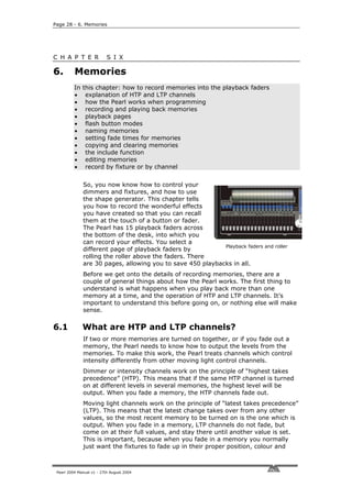
![6. Memories - Page 31
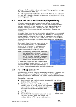
The legend for each memory is shown at the bottom of the VDU screen,
so you can see at a glance what is stored in each fader.
Labelling a memory
Hold down the AVO button and press G [Set Legend].
Press the Swop button of the playback you want to label.
Enter the label using the external QWERTY keyboard. The VDU
screen shows you what you are typing.
Press Enter to save the label.
You can label another memory by pressing another Swop button,
or finish by pressing Exit.
You can also label the playback pages, palette pages and palette entries
using the other softkeys.
Note: If you don’t have a QWERTY keyboard connected, you can enter
letters using the Swop and Flash buttons on Preset Faders 1-26.
The Swop buttons enter capitals and the Flash buttons enter
lower case letters.
If you don’t have a VDU screen, there is no point entering
memory legends as you need the VDU screen to see them. You
can, however, make use of Palette names on the LCD display.
6.7 Copying a memory
Copying a memory is very fast and simple.
Copying a memory
Hold down the Flash button of the memory you want to copy.
Press the Swop button of the playback you want to store it in
You can change the Roller page while you are holding down the
Flash button, if you want to copy a memory to a different page.
The new memory will be a linked copy of the old one. If you change a
memory which is linked, all the other memories linked to it will change
too.
You can create a completely separate copy of the memory using the
“Photocopy” function. Just press the Photocopy button (one of the blue
command buttons) before you start the copy. If you have named the
memory, the name will not be copied, indicating that it is a “new”
memory.
6.8 Deleting a memory
If you want to clear a memory so you can store something else in it:
Deleting a memory
Press Delete (one of the blue command buttons)
Press the Swop button of the playback you want to delete
Press the Swop button again to confirm the delete.
If the memory is linked to other memories, the others will not be
Pearl 2004 Manual v1 - 27th August 2004](https://image.slidesharecdn.com/pearl2004man270804-100221092248-phpapp02/85/Pearl2004-Man270804-39-320.jpg)
![Page 32 - 6. Memories
affected.
6.9 Editing memories
You can edit any part of a memory you have already saved simply by
making the changes and saving the new information on top of the
memory.
Editing a memory
Press Clear to empty the programmer.
Turn on the memory you want to edit, so you can see what you are
doing.
Select the fixtures you want to change, and make the changes.
Press Memory.
Press the playback swop button for the memory you are editing to
save the changes.
The Pearl will warn you “A memory already exists on playback!”
Press A [Merge memory].
The changes you have made are saved into the memory. None of the
other information in the memory is affected.
If you want to replace the memory with a new memory, you can use B
[Replace memory].
If you need to remove fixtures or individual attributes of fixtures from
the memory, you can use the “Off” function to do this. The “Off”
function is described in the reference manual.
6.10 The Include function
Sometimes it’s useful to be able to re-use some aspects of a memory
you have already created in another memory. If you’ve created a really
nice pattern of criss-crossing light beams, for example, you might want
to use it again in another memory with different gobos and colours.
Normally when you play back a memory, the information is not loaded
into the programmer, so you can’t simply turn on a memory, modify it
and save it to a new memory. The Include function lets you reload a
memory back into the programmer. You can then use it in a new
memory.
The Include function loads selected attributes of selected fixtures into
the programmer. So, for example, if you have a memory which
contains position, colour and gobo information for 8 fixtures, you can
use the Include function to load only the colour information for 4 of the
fixtures into the programmer. You could then “include” position
information from another memory into the programmer, and build up a
new memory using information from several existing memories.
Using Include
Press the Include button.
Select the fixtures from which you want to
take settings. If you don’t select any
fixtures, all fixtures will be used.
Select the Attributes you want to include.
Pearl 2004 Manual v1 - 27th August 2004
Include button](https://image.slidesharecdn.com/pearl2004man270804-100221092248-phpapp02/85/Pearl2004-Man270804-40-320.jpg)
![6. Memories - Page 33
The Dimmer attribute will include all other attributes (the lights on
the buttons show which attributes will be loaded).
Press the Swop button for the memory you want to include.
The selected attributes of the selected fixtures will be loaded into
the programmer.
You can Include an entire memory by ensuring no fixtures are selected
and selecting the Dimmer attribute.
If the memory you are including contains shapes, the shapes and all
the fixtures they are applied to will be loaded, whether they are
selected or not.
Include is also useful when you are programming chases, which is
described in the next section.
6.11 Setting fade times for a memory
You can set a fade in and fade out time independently for every
memory. The fades only affect HTP (intensity) channels, and are set
using softkey C for fade in and D for fade out. There is also a separate
LTP timer which allows you to set movement times for fancy sweeps or
colour fades, set using softkey E.
Setting fade times for a memory
Press C [Edit Time].
Press the Swop button of the playback you want to set times for
The display shows you the times you can set.
Press C to set Fade In time, or D to set Fade Out time.
Use the numeric keypad to enter the new time. Press Enter to save
it.
Press Enter when you have finished. If you press Exit, the changes
you have made will not be stored.
There are some other timing functions available as well, which are
described in the reference manual.
6.12 Record by fixture, record by channel modes
Normally, if you change one attribute of a fixture, the Pearl records all
the other attributes of that fixture even if you haven’t changed those
attributes. So if you change the pan position, the Pearl will also record
the tilt, colour, gobo, iris, and so on. However, the Pearl also has a
more selective mode of operation where it only records the changed
attributes. You can choose the mode by holding down the Avo button
and pressing Softkey C. The display shows the current setting of the
option.
• Record by fixture: This is the normal mode of the Pearl. It
means that when you record a memory, all attributes of every
fixture that you have changed are recorded in the memory. So if
you change only the position of a fixture, the colour, gobo,
intensity and all other attributes of that fixture are recorded as
well. This is useful because you know that when you recall the
memory, it will look exactly as it did when you saved it. However,
it can be slightly inflexible if you want to combine memories.
Pearl 2004 Manual v1 - 27th August 2004](https://image.slidesharecdn.com/pearl2004man270804-100221092248-phpapp02/85/Pearl2004-Man270804-41-320.jpg)

![7. Chases - Page 37
The display shows the step number
Press the playback Swop button to record the step. The
information from the programmer is stored as Step 1 of the chase.
Press Clear, set up the lighting for the second step, then press
Swop again to save step 2.
When you have saved as many steps as you want, press Clear,
then press Exit or Softkey F to finish.
If you don’t press Clear at the end of programming, the settings for the
last step will remain in the programmer and will override the chase
when you turn it on, so you won’t see the chase properly.
7.3 Running a chase
Running a chase is just like turning on a memory. Just raise the fader
and the chase will start to run.
The HTP (intensity) channels in the chase will be controlled by the
position of the fader. The other channels (LTP) will be set as soon as
the fader moves above zero. When in Run mode you can pre-position
the LTP channels to the first step by lowering the Add/Flash Master
fader to zero and pressing the Flash button of the
playback.
The chase normally starts at step 1, and runs
forward. You can pause the chase and change
the direction of the chase using the Sequence
control buttons to the right of the wheels.
There are lots of options you can set which let Sequence buttons
you do fancy things with chases, such as
Random, One-shot, special timing, and manual step mode. The details
are in the reference manual.
7.4 Setting speed and crossfade
When you run a chase, the wheels are assigned to control the Speed
and Crossfade of the chase (crossfade is the “slope” between steps,
from instant switching to continuous fading). The display above the
wheels shows the step time and the crossfade setting.
You can save a speed with the chase, so that every time you play it
back, it runs at the same speed.
Saving chase speed
Turn on the chase you want, and set the speed to the setting you
want.
Press A [Chase Parameters].
Again press A [Save Speed]
The display will show “Saved”.
You can also save the current direction of the chase by pressing softkey
B.
If you are running several chases, the wheels are assigned to the most
recently selected chase. You can “connect” the wheels to one of the
other chases by pressing the Connect button to the right of the wheels,
Pearl 2004 Manual v1 - 27th August 2004](https://image.slidesharecdn.com/pearl2004man270804-100221092248-phpapp02/85/Pearl2004-Man270804-45-320.jpg)
![Page 38 - 7. Chases
then the playback Swop button for the chase you want to connect to.
If you’ve changed the speed using the wheels and you want to go back
to the saved speed, press Connect then A [Clear temporary speed].
7.5 Naming chases
You can set a legend for chases in exactly the same way as you did for
a memory. In addition, you can label individual steps of a chase if you
are using the steps as cues. The reference manual tells you how to do
this.
Labelling a chase
Hold down the AVO button and press G [Set Legend].
Press the Swop button of the playback you want to label.
Enter the label using the external QWERTY keyboard (the VDU
screen shows you what you are typing) and press Enter.
You can label another memory by pressing another Swop button,
or finish by pressing Exit.
7.6 Editing a chase using Unfold
The Pearl has a powerful chase editing system. The Unfold button
places each step of a chase on one of the playback faders, allowing you
to examine and edit each step individually as if it was a normal
memory.
If your chase has more than 15 steps, you can swap to the next 15
steps using softkey F, or the previous 15 steps using softkey E.
Editing a chase using Unfold
Press the Unfold button (one of the blue command buttons)
Press the playback Swop button of the chase to be edited
The first 15 steps of the chase are loaded into playback faders 1-15
Raise a playback fader to view the contents of the step
The softkeys show a list of options which can be used for the step
To edit the contents of the step, make the changes then use
softkey A
To change the times of the step, use softkey B.
Press the Unfold button again to finish.
You can also edit chase steps while you are running the chase, without
using unfold. The “Rec Step” button allows you to record the current
programmer settings directly into the current step of the chase. This is
described in more detail in the reference manual.
7.7 Copying a chase
Chases can be copied in exactly the same way as memories.
Copying a chase
Pearl 2004 Manual v1 - 27th August 2004](https://image.slidesharecdn.com/pearl2004man270804-100221092248-phpapp02/85/Pearl2004-Man270804-46-320.jpg)
![7. Chases - Page 39
Hold down the Flash button of the chase you want to copy.
Press the Swop button of the playback you want to store it in
You can change the Roller page while you are holding down the
Flash button, if you want to copy a chase to a different page.
The new chase will be a linked copy of the old one. If you want to
create a completely separate copy of the memory, press the Photocopy
button before you start the copy.
7.8 Deleting a chase
If you want to clear a chase so:
Deleting a chase
Press Delete
Press the Swop button of the chase you want to delete
Press the Swop button again to confirm the delete.
7.9 Timing, Stacks and sequence control
The most common use of a chase is as an automatic continuous
sequence. However, the Pearl lets you step chases manually using the
Go button, which allows you to use them for theatrical lighting cues or
“One shot” chases. When you use a chase like this, it is sometimes
known as a “Stack”.
The Pearl has a dedicated theatrical lighting mode which is described in
detail in the next chapter.
Creating a stack
Save each cue state as a step in a chase.
Press C [Edit Times]
Press the playback Swop button for the chase
Press G [Links] to set LINK = OFF for the whole chase
Press Enter to save the setting.
Raise the playback fader to activate the chase.
Press the Go button to run each cue.
You can set the fade in and fade out times independently for each cue
using the Live Time button.
Setting cue times on a stack
Start the chase by raising the fader.
Press the Live Time button to set the times for the current cue.
Use softkeys A-G to set the times you want
Press Enter to save the settings or Exit to abandon them.
Press the Go button to go on to the next cue.
You can also set a text label for each cue. The Pearl will show you the
label for the current cue and the next one coming up. The reference
Pearl 2004 Manual v1 - 27th August 2004](https://image.slidesharecdn.com/pearl2004man270804-100221092248-phpapp02/85/Pearl2004-Man270804-47-320.jpg)
![Page 40 - 7. Chases
manual tells you more details about this.
7.10 Sound activation of chases
The Pearl can use bass, mid or treble (low, medium or high)
frequencies from its audio input to trigger chases. Any chase can be
programmed to respond to Bass, Mid or Treble frequency triggers.
There is also a master “Sound to light enable” option.
Sound mode only works with the key turned to Run, but you need to be
in Program mode to set up the chase for sound activation.
Sound activating chases
In Program mode, turn on the chase to “connect” it.
Press A [Chase Parameters]
Press E [Sound to light] to select Sound to Light Low, Medium or
High
Turn the key to Run mode.
Press E [Sound to light]. (This is the master sound to light enable
control) The option will highlight.
All chases with sound enabled will step in time to the sound signal
The Speed wheel controls the maximum speed of the chase
Press E, again, to turn off sound activation.
Also while in Run mode you can set the speed of the connected chase
manually by tapping Softkey G [Tap twice to set tempo] in time with
the music.
7.11 Examples
How do I program a dimmer chase?
Create the chase by pressing Chase then one of the flashing (empty)
playback swop buttons. Press Clear, and turn on the dimmers for step
1. Press the Swop button for the chase to save the step. Press clear,
then turn on the dimmers for step 2, and press the Swop button to
save. When you have saved all the steps, press Chase to end.
I’ve programmed a chase using memories but when I turn it on,
nothing happens
To use existing memories in a chase, you must use the Include function
to load the memory into the programmer. If you just turn on a memory
and then try and save that as a chase step, nothing will be saved
because the memory will not be in the programmer.
The last step of my chase doesn’t play back
You need to press Clear to clear the programmer (which overrides the
chase output).
Pearl 2004 Manual v1 - 27th August 2004](https://image.slidesharecdn.com/pearl2004man270804-100221092248-phpapp02/85/Pearl2004-Man270804-48-320.jpg)

![Page 42 - 8. Theatre stack
C H A P T E R E I G H T
8. Theatre stack
In this chapter: the Pearl’s theatre mode
• Setting theatre mode
• Theatre controls
• Plotting a cue
• Naming a cue
• Setting fade times for a cue
• Jumping to a cue
• Running the show
Theatre mode makes the Pearl behave like a standard theatrical
console, allowing you to program your whole show as a sequence of
cues, and play it back just by pressing the Go button. Playback faders
12-15 become dedicated cue masters. The rest of the console continues
to operate as normal, so you can run the main cues from the theatre
mode, and spot effects from the other playback faders.
8.1 Setting theatre stack mode
In program mode, select Softkey B [Theatre stack programming], then
press Enter.
Note: When theatre mode is enabled, you can’t access playbacks 12-
15 on any page; if you intend to use Theatre mode it is
advisable not to program these playbacks. Any programs are
kept and when you turn off Theatre mode you will be able to
access them again.
You can get out of the Theatre menu by pressing G [Quit]. The Exit
button does not operate in this mode.
To turn off theatre mode completely, press softkey B from the main
menu then press D [Exit theatre programming] When Theatre mode is
enabled, the swop button of Playback 12 flashes when the playback is
turned off.
Theatre mode programming is not deleted when theatre mode is turned
off.
8.2 Theatre controls
Fader 12 is the Master fader, controlling the overall intensity of all
lights.
The Go button next to the wheels makes a cue start.
If you stop a fade part-way by pressing the Stop button, or one of the
stop buttons above the faders, then Fader 13 controls the Fade In of
the next step, fader 14 controls the Fade Out of the previous step, and
fader 15 controls the LTP (movement) fade timer.
The buttons above 13, 14 and 15 are Stop (blue) and Go (grey) buttons
for each of these functions.
8.3 Plotting a cue
You can set up the levels for a cue either by using the preset faders and
Pearl 2004 Manual v1 - 27th August 2004](https://image.slidesharecdn.com/pearl2004man270804-100221092248-phpapp02/85/Pearl2004-Man270804-50-320.jpg)
![8. Theatre stack - Page 43
control wheels to set the levels you want, or by typing in the channel
number and the level. You can store moving light positions in theatre
cues as well as dimmers.
Entering dimmer levels
Press Channel (at the top of the numeric keys)
On the numeric keypad, enter the fader/handle number of the
dimmer (not the DMX address of the channel)
Press G [At %]
Enter the value to be set as 0 – 9, or Softkey G for Full. You can
enter a decimal point and another number if you want more
accurate level control.
The channel you entered will be set to the level you entered.
Press the Channel button to go back to the normal menu
The softkeys offer you a few more options such as up by 5%, down by
5%, blackout.
Pressing Clear will take all channels you’ve set using the keypad to
blackout. Any channels turned on using the faders will stay on, but will
be removed from the programmer.
You can also set multiple channels to the same level using F [through].
Enter first channel, “through”, last channel, “at %”, level.
Entering multiple dimmer levels
Press Channel
On the numeric keypad, enter the first dimmer handle number of
the range
Press F [Through]
Enter the last dimmer handle number of the range
Press G [At %]
Enter the value to be set as 0 – 9, or.Softkey G for Full.
The channels you entered will all be set to the level you entered.
When you have set all the levels as you want them, type the cue
number, then press D [Record Menu]. You then need to press B
[Record Stage] to record all the intensity channels that are currently
turned on, plus anything in the programmer, or D [Record
Programmer] to record just the contents of the programmer (i.e. what
you have manually changed). The cue will be saved.
It’s best to use whole numbers for cues. Then if you need to insert a
cue between two existing cues, you can use a fractional number in
between. The Pearl will automatically increase the cue number by 1
every time you record a cue.
8.4 Naming a cue
Type the step number to be named, then press E [Set Legend]. Enter
the legend on the QWERTY keyboard. While you are typing, the input is
shown on the VDU screen.
The name of the live cue and the next cue is displayed in the cue list on
Pearl 2004 Manual v1 - 27th August 2004](https://image.slidesharecdn.com/pearl2004man270804-100221092248-phpapp02/85/Pearl2004-Man270804-51-320.jpg)
![Page 44 - 8. Theatre stack
the VDU screen.
8.5 Setting fade times for a cue
You can set fade in, fade out and “wait” times for each cue. Press C
[Set Times] to show the options. This will set the times for the current
cue. You can also use the “Live Time” and “Next Time” buttons (to the
right of the wheels) to set the times for the current and next cues. See
page 165 for details of times.
8.6 Jumping to a cue
You can change the cue being edited by typing the cue number then
pressing Enter. If you want to output this cue, press F [Cut to Live]
(fade times are ignored).
8.7 Running the show
If you have just been editing, you may need to type 1 then Softkey F to
set the console to cue 1.
The display above the control wheels shows the current cue number,
the next cue number, and the progress of the wait and fade times for
fade in, fade out and LTP.
For automatic cues, you can simply press
In HTP fade Out HTP fade
the Go button next to the wheels. The
console will carry out the fade with the
times you programmed.
If you want to manually control a fade, you
can use the in, out and LTP faders or
Go/Stop buttons to operate the cue. The
display just above wheel A shows the
percentage of fade (9 - 0) left to go (shown
as “5” in the picture). When Fade In, Fade
Out and LTP all show “0”, the console
cue numbers LTP fade
moves on to the next cue.
Pearl 2004 Manual v1 - 27th August 2004](https://image.slidesharecdn.com/pearl2004man270804-100221092248-phpapp02/85/Pearl2004-Man270804-52-320.jpg)

![Page 48 - 10. Running your show
C H A P T E R T E N
10. Running your show
In this chapter: running your show with the Pearl 2004
• Showtime
• Run modes
• Master faders
• Channel mimics
• Manual control during a show
10.1 It’s showtime…
When you have finished programming (or you’ve run out of time) and
it’s showtime, the most important thing is to back up the show to disk
(see end of section 2 on page 12 for instructions). Having done that,
turn the key to Run. This means you can’t accidentally change your
programming when you get into a button-pressing frenzy.
10.2 Temporarily locking the console
In Run mode you can temporarily lock the console (to stop the sound
guys playing with it while you nip to the loo). Type in a 4 digit number
then press C [Lock Desk] then Enter. The display will show the code.
Press Enter to lock it. All buttons and faders are now ignored. Re-enter
the code to unlock the console.
If you repower or reset the Pearl, the lock is cancelled. It’s just to
discourage tampering.
10.3 Run modes
When you are running a show, there are two modes available to you,
normal Run mode, which just allows you to play back memories, and
Takeover run mode, which allows you to play back memories and also
take manual control of fixtures. The mode also affects how the Swop
and Flash buttons on the console operate.
You can select the mode by pressing A [Toggle mode]. The mode is
shown on the top line of the display.
• What’s not affected: The playback faders work the same in either
mode. The Preset Faders work as handles to control the intensity of
the device they are patched to.
• Normal Run mode: the Flash and Swop buttons on the handles and
playbacks work as flash buttons. The “Flash” button adds the function
into anything else which is on. The “Swop” button turns on the
function, but turns off everything else while the button is held down.
The programmer is cleared and you can’t manually control any LTP
channels.
• Takeover run mode: the Swop buttons on the handles allow you to
select dimmers or fixtures for manual control. This lets you add to or
change your programming in real time during the show. The faders still
control the intensity of the dimmers and fixtures. The Flash and Swop
buttons on the playbacks are disabled.
Pearl 2004 Manual v1 - 27th August 2004](https://image.slidesharecdn.com/pearl2004man270804-100221092248-phpapp02/85/Pearl2004-Man270804-56-320.jpg)


![1. Setting up the console - Page 111
1.1.6 The desk lamp
The desk lamp plugs into the socket in the top left hand corner of the
Pearl and can be switched to Off, Dim or Full using the switch next to it.
The desk lamp uses a 12V, 5W halogen lamp.
1.2 Operating
1.2.1 Operating modes
The Pearl has a key-operated switch on the right hand side of the panel
which allows you to select the operating mode of the console.
When running a show, you normally select Run mode. You can run
playbacks and (in Takeover run mode) manually control fixtures (see
page 180). You cannot change any programming. This is the best mode
if others are operating the console and you want to make sure they
can’t mess up your programming. Just take the key with you!!
When programming, you need to be in Program mode, which you
access by turning the key to Program. This manual assumes you are in
program mode.
System mode allows you to clear parts or all of the console using
softkey F [Wipe], to access AVO mode, various diagnostics and to load
a new operating system. There are more details about AVO mode in
Section 13 on page Error! Bookmark not defined..
1.2.2 The disk drive
The Pearl has a 1.44MB floppy disk drive which is used to load and save
shows, personality files and system software. The standard PC disk
format is used, so you can transfer data to and from your PC. You can
use the smaller 720KB disks, but large shows may not fit!
You should get into the habit of backing up your show to disk regularly
to guard against that moment when something goes wrong. It doesn’t
take long.
1> Press the Disk button in the bottom right hand corner of the Pearl
2> Insert a blank formatted 1.44M disk into the disk drive.
3> Press B [Save show to disk]. Enter a name on the QWERTY
keyboard (or press Enter on the console to use the default name).
The Pearl will save the show.
4> To reload the show, use softkey A [Load show from disk].
Other disk drive functions are available when you have pressed the
Disk button. The disk drive functions are described in section 13 on
page 194.
Pearl 2004 Manual v1 - 27th August 2004](https://image.slidesharecdn.com/pearl2004man270804-100221092248-phpapp02/85/Pearl2004-Man270804-83-320.jpg)
![1. Setting up the console - Page 113
fixtures, and to set chase speeds and fades.
• The Menu softkeys (labelled A – G) are used to select control
options. The display next to the buttons shows what each one will
do. The options for each key change depending on what the
console is doing. Softkey commands are shown in the manual with
square brackets like this: A [Chase Parameters]
• The Numeric keypad and other control buttons are used to enter
values and change controls on the console.
• The Fixture Page buttons are below the keypad, which select 4
pages for the Preset Faders.
• The blue Command buttons are used to carry out functions such
as storing memories, copying, saving to disk, etc. These buttons
have lights on to indicate when they are active.
• The Attribute select buttons are used to select which attributes
of a fixture (e.g. colour, gobo, pan, focus) are going to be
controlled using the Control wheels. The buttons have lights on to
show you which attributes are active. The bottom (red) button
allows you to reduce the intensity of a fixture if it loses position
during a show.
1.2.4 View screens
The Pearl can display a wide range of different information screens on
its inbuilt LCD and on the external VDU screen.
LCD views
Message area Softkey functions
• Channel Output: Press
View then Softkey A.
Shows the output of the
selected attribute for each
handle. You can change Main
the attribute by pressing a display
different attribute button area
(Dimmer, tilt/pan etc).
The display only shows the
first 30 handles, press the
current Pages Of Fixtures
button to show 31-60.
• Fixture attributes: Press
View
View then Softkey B. screen
Shows which attributes of number
the currently selected
fixture are allocated to Chase
info
wheel A and wheel B. The
view will be blank if no
fixtures are selected. Wheel functions free memory
and values
• DMX Patch: Press View
then Softkey C. Shows
which fixture each DMX output channel is patched to, the attribute
of that fixture, and the actual DMX value being output on that
channel. Use the arrow keys to show different pages of the patch.
• Fixture Patch: Press View then Softkey D. The top part of the
display shows a list of handles with the fixtures patched to them.
An arrow shows the active fixture; some fixture types will display
Pearl 2004 Manual v1 - 27th August 2004](https://image.slidesharecdn.com/pearl2004man270804-100221092248-phpapp02/85/Pearl2004-Man270804-85-320.jpg)


![Page 118 - 2. Patching
2.1.2 Patching dimmers
Each dimmer channel is allocated to one handle. If you want to link
dimmers together, you can allocate several to the same handle.
1> Press Patch, then A [Dimmer]
2> On the top line of the display, the Pearl shows the DMX address it
is going to patch at. You can change this by typing a new address
on the numeric keypad. You can also use softkey E [Select a DMX
line] to patch onto one of the other 3 DMX output lines.
3> To patch a single dimmer, press a handle Swop button. To patch a
range of dimmers, hold down the Swop button for the first
dimmer in the range, then press the last Swop button in the
range. The range of dimmers will be patched to sequential DMX
addresses.
4> To patch another dimmer to the same handle, enter the new DMX
channel and press the Swop button again
5> Repeat from step 2 for other dimmers.
• The VDU screen will
show the channels
which have been
patched.
• You can patch
multiple dimmers
onto the same
handle by typing
the DMX address of
the next dimmer to
be patched and
pressing the Swop
button again.
• You can patch
Grid showing usage Devices patched
dimmers to the top of DMX channels
faders (31-60) by
holding down the AVO button before pressing the Swop button.
This allows you to patch up to 60 dimmers or fixtures on one page.
It is often convenient to use the top faders for dimmers and the
bottom faders for fixtures allowing you to keep all your fixtures and
dimmers on one fixture page.
• When in Dimmer Patch mode you can set options for dimmer
channels which you are going to patch. You can set the “Full on”
level to less than 100% using option A, and select a different
dimmer response curve using option B. To use the “User curve”
setting you need to load in a user curve, see page 194. These
settings affect all dimmer channels you patch afterwards, until you
change the settings again. Channels you have already patched are
not affected.
2.1.3 Patching moving light fixtures
Moving light fixtures are more complicated to patch than dimmers
because they have more attributes to control, such as pan, tilt, colour
etc., where a dimmer channel just has intensity. When you patch a
fixture, you will see on the display that it occupies a block of DMX
channels rather than just one.
Pearl 2004 Manual v1 - 27th August 2004](https://image.slidesharecdn.com/pearl2004man270804-100221092248-phpapp02/85/Pearl2004-Man270804-90-320.jpg)
![2. Patching - Page 119
The Pearl uses a “personality” system to control fixtures. There is a
personality file in the Pearl for most types of fixture, which tells it what
attributes are available and how to control them. If the Pearl does not
have the personality for your fixture, you can download a wide range of
personalities from the Avolites website onto floppy disk and load them
that way. If you use fixtures often you can add them to the internal
store. In the unlikely event that no personality exists for the fixture you
are using, Avolites will create one for you. You can also create the file
yourself if you have some programming abilities. See chapter 12 on
page 206 for details of how to find personalities.
Note: The Pearl holds all the personalities in an internal “cache” file. If
the console memory gets totally wiped you might need to
reload the file, how to do it is described on page 196. You can
also use a Personality Disk in the disk drive.
If you are using the internal personality cache, ensure there is no disk
in the disk drive.
1> Press Patch, then B [Choose a Fixture].
2> The Pearl will read the personality files, then display “Please select
an instrument”. A list of known fixtures will appear next to the
softkeys after a pause.
3> Use F [More] and G [Back] to go up and down the list and find the
correct fixture, then press the softkey next to the fixture to select
it.
4> The Pearl loads the fixture information. The display shows details
of the fixture.
5> The Pearl will ask “Use preset palettes?”. Press A [Yes]. This loads
a standard set of positions, colours and gobos into the Palette
pages which can be useful when programming. If you say No now,
you can’t load them later.
6> On the display, the Pearl shows the DMX address it is going to
patch at. You can change this using the numeric keypad. You can
also press E [Select a DMX line] to patch onto one of the other 3
DMX output lines.
7> Press an unused handle Swop button to patch the fixture. The
VDU screen will show the block of channels occupied by the
fixture. If you want to use a different fixture page, select the new
page first.
8> Repeat from Step 7 to patch more of this type of fixture.
9> Press A [Select another fixture] and repeat from Step 3 to patch a
different type of fixture.
• You can patch a range of fixtures by holding down the first and
last Swop buttons of the range, the same as for dimmers.
• Unlike dimmers, you cannot patch more than one fixture onto a
handle. If the handle is already used, the patch will fail. Use a
different handle or delete the fixture already on the handle if you
don’t want it any more.
• Some fixtures can only be patched at certain DMX addresses. This
is usually described in the fixture instruction manual. If this
information is included in the fixture personality, the Pearl will not
allow you to patch the fixture at an illegal address, and will offer
Pearl 2004 Manual v1 - 27th August 2004](https://image.slidesharecdn.com/pearl2004man270804-100221092248-phpapp02/85/Pearl2004-Man270804-91-320.jpg)
![Page 120 - 2. Patching
the next valid address instead.
• If you are patching a fixture which uses a separate dimmer
channel such as a VL5™, you can patch the dimmer channel onto
the same handle as the moving light part of the fixture, so you
can control it all together. This is called a Pending dimmer.
2.1.4 Checking the patching
Having set the Pearl, you need to ensure that your lighting rig is set up
to match the Pearl by going round your rig to set the DMX addresses.
You can display the DMX settings on the Pearl like this.
1> Press the View button next to the numeric
keys
2> Press D [Fixture Patch]
3> The display shows a list of the handles to
which you have patched fixtures or
dimmers, with the DMX line and address
(e.g. A24 is address 24 on DMX line A).
4> The top handle on the list has an arrow
next to it. The lower part of the display
shows more information for this handle,
including dip switch settings if the fixture
personality includes this information.
5> Use the up-down cursor arrows to change
the selected fixture. The left-right cursor
arrows will show you another page of
handles.
6> Repeat from Step 4 to view other fixtures.
• Press View, then C [DMX patch] to display a list of all DMX
channels, what they are allocated to and the current output. The
cursor arrows scroll through the list.
• Press View then a handle Swop button to display the settings for
the fixture patched to that handle.
• You do not need to be in patch mode to view this information, you
can do it at any time.
2.2 Edit
2.2.1 Changing the DMX address of a fixture
You can re-patch a fixture to a different DMX address or a different
DMX output line. All programming is kept.
1> Press Patch (if you’re not already in Patch mode).
2> Press E [Repatch Fixtures].
3> Use the numeric keypad to enter the new DMX address of the
fixture. If you want to change the DMX output line, press E
[Select a DMX line] and choose a new output line by pressing A B
C or D.
4> Press the handle swop button for the fixture to patch that fixture
at the new address.
Pearl 2004 Manual v1 - 27th August 2004](https://image.slidesharecdn.com/pearl2004man270804-100221092248-phpapp02/85/Pearl2004-Man270804-92-320.jpg)
![2. Patching - Page 121
5> Press Enter to confirm the change.
6> Repeat from step 3 if you want to change other fixtures.
• If the new DMX address was already used by another handle, the
fixture or dimmer on that handle will be “parked”. All
programming for the handle is preserved, but you need to patch it
to a new DMX address using the above procedure before you can
use it again. If you view the fixture patch as described above, the
display will show “park”.
2.2.2 Moving a fixture to a different handle
You can move a dimmer or fixture from one handle to another simply
by entering the DMX channel to match the address of the fixture, then
patching it again onto another handle. However, all programming is lost
for that dimmer channel or fixture.
2.3 Delete
2.3.1 Deleting a patched fixture
You can delete a fixture or dimmer from a handle if you patched it
accidentally or if you change your rig and want to use the handle for
something else.
1> Press Patch (if you’re not already in Patch mode).
2> Press the blue Delete button (the light will flash).
3> Press the Swop button of the handle you want to delete.
4> Press Enter to confirm.
• You can delete individual DMX channels from a handle by typing
the channel number instead of pressing a Swop button. This is
useful for deleting dimmer channels from handles which have
multiple channels patched to them. Be careful not to delete
individual channels out of fixtures using this function.
2.4 Advanced options
2.4.1 Patch Utilities
The Pearl allows several options to be set for each fixture or dimmer
when it is being patched. The Patch Options menu is accessed by
pressing F [Patch Utilities] while you are in patch mode. Set the options
before you start programming, because memories will play back
differently when the options are on.
The options are:
A: Invert - Allows you to invert an attribute of a fixture, so when you
set zero the output will be full. You cannot invert some attributes.
1> Select the fixtures you want to invert and turn them on so you
can see their output state
Pearl 2004 Manual v1 - 27th August 2004](https://image.slidesharecdn.com/pearl2004man270804-100221092248-phpapp02/85/Pearl2004-Man270804-93-320.jpg)
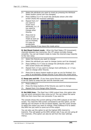

![3. Controlling dimmers and fixtures - Page 125
C H A P T E R T H R E E
3. Controlling dimmers and fixtures
This chapter contains: Selecting fixtures and dimmers for control;
changing attributes of the selected fixtures; using groups; selecting
fixtures one at a time; the align and flip buttons; killing off a fixture;
entering levels as numbers; the ML menu and tracking; viewing the
output.
When you are programming a show, and sometimes when you are
running a show, you need to manually control the fixtures and dimmers
to set the intensity, position, colour, etc. To do this you first select the
fixtures you want to change using the Swop buttons, then you set the
attributes of those fixtures using the Wheels and Attribute buttons.
3.1 Create
3.1.1 Selecting fixtures and dimmers for control
To select the fixtures or dimmer channels that you want to control, you
use the handle Swop buttons. You can select fixtures or dimmers
individually, or several at once.
You can control dimmer channels and fixture intensity directly from the
fader control of the handle, or select the channels as described below
and use the Dimmer attribute.
1> Press the handle Swop buttons for the fixtures you want. The LED
in the Swop button comes on for selected fixtures (they are also
shown in dark blue on the VDU screen)
2> To select a range of fixtures, hold down the Swop button for the
first fixture then press the Swop button for the last fixture.
Here are some other things to know:
• Press ML Menu then A [Locate Fixture] to position the selected
fixtures in open white at a central position (dimmer channels go to
50%). These values are not loaded into the programmer - they
won’t be saved in a memory unless you modify the fixture.
• If you want to light up a fixture without moving its position, use B
[Locate Fixture no Pan & Tilt]”.
• You can deselect a fixture by pressing the fixture select button
again.
• Once you have changed any attribute, pressing a handle Swop
button will deselect all fixtures and start the selection process
again.
• You can select fixtures on another page by pressing one of the
“Pages of Fixtures” buttons.
• If you have fixtures patched to the top faders you can select them
by holding down the AVO button and pressing the Swop button of
the fader below.
Pearl 2004 Manual v1 - 27th August 2004](https://image.slidesharecdn.com/pearl2004man270804-100221092248-phpapp02/85/Pearl2004-Man270804-97-320.jpg)
![Page 126 - 3. Controlling dimmers and fixtures
3.1.2 Changing attributes of the selected fixtures
“Attributes” are the functions of the fixture, like pan, tilt, colour,
dimmer, etc. You select which attributes you want to modify using the
buttons on the right edge of the console Attribute select buttons
and set values using the wheels at the
bottom of the Pearl. The attributes
available depend on the fixture type.
Dimmer channels only have a dimmer
attribute. The Pearl can control up to 40
attributes per fixture.
Each attribute button controls two
attributes, one on the left wheel and
one on the right wheel.
1> Press the button for the attribute
to be changed
2> Turn the wheels to set the Control wheels
attribute. The display above the
wheels shows which attributes are being controlled.
3> Repeat from 1 to change other attributes of the selected fixtures.
Some other things to know about attributes:
• The Attribute buttons let you select the first 20 attributes. Another
20 attributes are available by pressing the “Attribute Banks 11-20”
button, to cater for the weird and wonderful DMX fixtures of the
future. The light on the button stays on when you are using the
top 20 attributes.
• If the display above the wheels does not show the attribute when
you press the button, that attribute is not available on the
selected fixtures.
• You can directly control the intensity of the fixture/dimmer using
the fader of the handle.
• You can view the available attributes by pressing the View button
then B [Fixture Attributes]. The display shows a list of available
attributes for the fixture you’ve selected.
• The wheels operate in an “acceleration” mode. If you spin the
wheel fast, the fixture changes in larger steps. If you move the
wheel slowly, the fixture moves in its smallest increment. (This
replaces the 16-bit mode found on older Pearl software). You can
change the acceleration response of the wheels by holding down
AVO and pressing 2 (see page 194 for details). You may want a
different response for very fine adjustments, or to suit your wheel
spinning style.
• Holding down AVO while turning a wheel puts the wheel into
“hyper-drive” mode where one complete revolution takes the
attribute from 0 to 100%.
• The display above the wheels either shows the output value
(percentage and raw DMX value), or it can show Intelligent
Attribute Display (for a colour wheel, the display would show
“Open”, “Red”, “Orange” and so on as you turn the wheel). Hold
down AVO and press 1 to enable or disable Intelligent Attribute
display. The personality fixture must have Range Tables for this to
work.
Pearl 2004 Manual v1 - 27th August 2004](https://image.slidesharecdn.com/pearl2004man270804-100221092248-phpapp02/85/Pearl2004-Man270804-98-320.jpg)
![3. Controlling dimmers and fixtures - Page 127
3.1.3 Selecting attributes from the softkeys
You can directly set attributes from the softkeys.
1> Press E [Select an attribute or table] from the main menu
2> Select an attribute type to set. If the attribute is highlighted, a list
of possible settings will appear when you press it (for example, a
list of possible colours)
3> Select the value you want by pressing a
softkey.
4> Repeat from 1 to change other attributes
of the selected fixtures.
• The Wheel A and B windows display the
table of available values. You can also use
the wheels to scroll through the settings.
• If the attribute type is not highlighted,
there are no settings available. Pressing
the softkey for that attribute will change
the selected attribute button but not do
anything else.
• Selecting a value from a list will select
attribute banks 11-20. You’ll need to press
the Attribute Banks 11-20 button to get back to the normal
attributes.
3.1.4 Using groups
You can create groups of fixtures or dimmer channels, to make
selecting them faster. You can, for example, make a group for each
type of fixture, or group by left / right stage, etc.
1> Select the fixtures/dimmers you want in the group (the order in
which you select them will also be stored in the group)
2> Press ML Menu, then E [Record Group]
3> Type the group number you want to store it as, and press Enter
4> Repeat from 1 to store other groups
Other useful things to know about groups:
• To select all the fixtures/dimmers in a group, type the group
number on the numeric keypad, then press A [Recall Group]. All
other fixtures and dimmers are deselected.
• The order in which you select the fixtures takes effect when you
use the last fixture – next fixture functions described in the next
section, and when you use Shapes and Fan mode.
3.1.5 Stepping through selected fixtures one at a time
If you have selected a range of fixtures, or a group, the Pearl has
functions to step through the selected fixtures one at a time. This can
make it easier to program a range of fixtures because you don’t have to
select each one manually.
This mode uses the “Sequence Control” buttons which are normally
used for controlling chases.
Pearl 2004 Manual v1 - 27th August 2004](https://image.slidesharecdn.com/pearl2004man270804-100221092248-phpapp02/85/Pearl2004-Man270804-99-320.jpg)
![Page 128 - 3. Controlling dimmers and fixtures
1> Put the Pearl into Fixture Select mode by holding down the AVO
button and pressing Softkey B until
the option shows [Fixture Control
Enabled]
2> Select a range of fixtures or a
group
3> The (Reverse) and (Forward)
buttons will select the fixtures in
the range one at a time
4> The (Bounce) button will
highlight the output of the selected
fixture so you can see it on stage
(the button LED is lit when in Sequence control buttons
Highlight mode)
5> The Review button reselects the whole range of fixtures.
• The Sequence Control buttons stay in this mode until you change
them back by holding AVO and pressing Softkey B again. This
means you cannot use them for controlling chase direction.
• You can also use the left and right arrow keys to step through
selected fixtures.
• The selected fixture from the range will light up, and the other
fixtures will go out (if the “Highlight Enabled” option in the ML
menu is turned on).
3.1.6 The Align and Flip functions
The Align function allows you to copy an attribute from one fixture to
others. This can be useful if you want to set a row of scans to have the
same tilt position, or if you want to copy a colour from one fixture onto
other fixtures.
1> Press an attribute button to select the attribute you want to align.
2> Select the fixture to use as the reference
3> Select the other fixtures you want to align to the first one
4> Press ML Menu, then D [Align <attribute name>].
5> The attributes will be copied to all the selected fixtures.
• You can align all attributes of the fixtures using Softkey C [Align
Fixtures] (it doesn’t matter which attribute is selected).
• If you use a group to select the fixtures, the one you selected first
when you recorded the group will be the reference fixture.
• If Tracking mode is on (see page 131), aligning the Pan/Tilt
attribute will cause all the fixtures to point at the same place on
the stage rather than copying the actual Pan/Tilt values.
The Flip function is used with moving head fixtures. This type of fixture
has two possible pan and tilt positions for each point on stage, and the
Flip button alternates between them. This allows you more freedom to
make movements without hitting the pan stop.
1> Select the fixtures to flip.
2> Press ML Menu twice (option A should be Flip)
3> Press A [Flip].
Pearl 2004 Manual v1 - 27th August 2004](https://image.slidesharecdn.com/pearl2004man270804-100221092248-phpapp02/85/Pearl2004-Man270804-100-320.jpg)
![3. Controlling dimmers and fixtures - Page 129
• The other functions on the ML menu are described at the end of
the chapter.
3.1.7 “Killing off” a fixture or dimmer
Sometimes during a show you might want to “kill” a fixture or dimmer
from the stage output. This may happen if a camera is having problems
with a light shining straight into it, if a lamp blows and you want to
keep the rig symmetrical or if a fixture loses position.
The “Reduce fixture intensity” button allows you to temporarily dim or
turn off any fixture or dimmer. Programming is not affected and you
can later restore it to normal operation. You can do this in program
mode or run mode. You have to hold down the AVO button to access
the function to stop it being accidentally pressed.
1> Hold down the AVO button and press “Reduce Fixture Intensity”
(in the lower right corner).
2> Put the fader for the fixture/dimmer channel to be reduced up to
full (if it was already full, take it to zero then up to full).
3> Reduce the fader to the intensity level you want.
4> Repeat from 2 to reduce other fixtures.
5> Press Reduce Fixture Intensity to finish.
• To restore the fixture, do the above but leave the fader at full. The
fixture will stay “reduced” until you restore it.
• Make sure you turn off Reduce Fixture Intensity when you have
finished, otherwise you will end up reducing intensities when you
don’t want to, and wondering why none of your fixtures are
coming on.
• To cancel all reductions, put all faders to zero, then press the
Reduce Fixture Intensity button and put all faders to full, then
press the button again to end.
• If the Swop buttons are in “mimic” mode (see page 182), they will
show the programmed output of the channel, not the reduced
output.
3.1.8 Entering intensity levels as numbers
You can set levels using the numeric keypad as you would on a
theatrical lighting desk. If you are used to doing this, it can be faster
when plotting dimmer levels for a scene than using the select buttons
and the wheels.
1> Press the Channel button
2> Type the dimmer or fixture handle number (not the DMX channel)
on the keypad.
3> Press G [At %].
4> Press 0 - 9 for the intensity (0=0%, 1=10%, 2=20%, 3.5=35%),
or Softkey G again for 100%
5> Press the decimal point key and another digit for more accurate
control
6> Press Channel again to get back to normal (the Exit button does
not operate in this mode)
Pearl 2004 Manual v1 - 27th August 2004](https://image.slidesharecdn.com/pearl2004man270804-100221092248-phpapp02/85/Pearl2004-Man270804-101-320.jpg)
![Page 130 - 3. Controlling dimmers and fixtures
Other things you can do by numeric entry:
• The softkey options are B: Blackout, D or G: set to 100%, E:up by
5%, F:down by 5%.
• You can select multiple dimmer handles (which you can then
control using the wheels) using softkey F [Through]. Enter the first
dimmer number, press [Through], then the last dimmer. For
example 1 Through 10 would select dimmers 1 to 10.
• You can also set multiple dimmers to the same level using softkey
F [Through]. Enter first dimmer number, [through], last dimmer,
[At %], level. For example, 1 [Through] 1 0 [At%] 5 would set
dimmers 1 to 10 to 50%.
• Softkey B [Select new fixture type] lets you tell the desk the type
of fixture you are working with. It uses this when you select
fixtures. Normally it is set to “desk channel” and will select fixtures
starting from handle 1. If you set it to dimmer, it will only select
dimmers, starting at the first dimmer patched, so selecting 1
“through” 10 would select the first 10 dimmers, wherever they are
patched. You can set the option to any fixture type you have
patched on the console.
• If you have more than one dimmer/fixture selected, Softkey C
[Odd or Even], allows you to select the odd and even numbered
channels. Softkey B selects Even channels and C selects Odd
channels. Softkey A selects all channels again after you have used
this option.
• Softkey E [Select Group] allows you to recall a group by entering
the group number.
3.1.9 Controlling fixtures by entering values
You can also directly enter values for fixture attributes. This can be
useful for programming palette values from a fixture data sheet.
1> Select the fixtures to be set by pressing the Swop buttons
2> Select the attribute to be set using the Attribute buttons
3> Type the value to set.
4> Press Softkey E or F to set the A/B wheel attribute (displayed next
to the softkey).
5> Press G [Set input to 0-255 / %] to change the entry mode
between 0-100 and 0-255.
• You can change the attributes to be set by pressing another
Attribute button, but then you will need to enter the value again.
• You can also recall groups of fixtures or dimmers (type group
number, then press A [Recall Group]).
• You can recall palette entries (type palette entry number, then
press B [Recall Focus])
3.1.10 Fan mode
Fan mode automatically spreads out the values on a selected range of
fixtures. If used on pan and tilt, the result is spreading out “rays” of
light beams. The first and last fixtures of the range are affected most,
and the central fixtures are affected least. The amount of fan can be set
using the wheels.
Pearl 2004 Manual v1 - 27th August 2004](https://image.slidesharecdn.com/pearl2004man270804-100221092248-phpapp02/85/Pearl2004-Man270804-102-320.jpg)
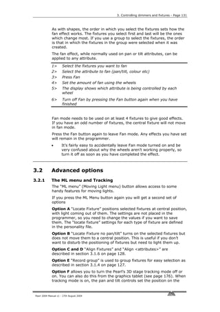
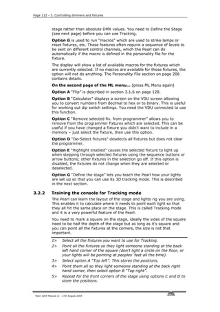
![3. Controlling dimmers and fixtures - Page 133
6> Press Enter to complete the process.
7> The Pearl will go away and do lots of calculations. The top line of
the LCD shows the progress. This can take several minutes.
8> Press ML menu then Softkey F to enable Tracking mode (option
shows [Tracking On (Off)] when tracking is enabled)
• You can recall a position you have already set, if you want to edit
it, using F [Recall] then A B C or D to recall one of the positions.
• You need to make sure you are lighting a person rather than
making a spot on the stage, because otherwise the beams will
cross over at the wrong place. If you can’t find a handy spare
person, use a plastic cup or a light coloured item of clothing over
the end of a mic stand at head height.
• If you are using moving head fixtures, you need to ensure when
hanging them that the pan stop is on the side away from the
stage, or the fixtures will not be able to track over the whole stage
area. You also need to keep the Tilt value less than 50%, or the
heads may “flip” when you track into some areas.
• Fixtures which have not been trained for Tracking will operate as
normal when tracking mode is enabled.
• When Tracking mode is turned on, the VDU screen shows “T” in
the top right hand corner.
Pearl 2004 Manual v1 - 27th August 2004](https://image.slidesharecdn.com/pearl2004man270804-100221092248-phpapp02/85/Pearl2004-Man270804-105-320.jpg)

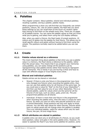
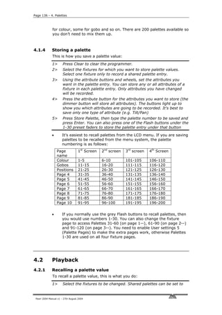
![4. Palettes - Page 137
any fixture of the same type. Individual palettes will set individual
values to each fixture.
2> Select the attributes you want to recall from the palette. The
Dimmer attribute button will recall everything stored in the palette
(the LEDs on the buttons show you which attributes are active)
3> Press the Focus button, then the palette
page you want if the pages are
displayed, then press the softkey for the
palette entry you want (or Softkeys F
and G go up and down the list). The
selected attributes of the fixtures will be
set to the palette values. The console
will stay in “Apply palette” mode until
you press Exit.
• It’s easiest if you only save one type of
attribute (such as pan/tilt) into each
palette, then you can just leave the
Dimmer attribute button selected when
recalling the palette. If you store a
mixture of attributes, you always have to
make sure that the correct attributes are
selected when recalling a palette, and this is an extra step which
you could do without.
• You can also use the grey Palette/Flash buttons below the preset
faders to apply palettes 1-30. While you hold the button, the top
line of the display shows the legend for the attribute (White,
Green etc). When you release the button, the palette is applied. If
you decide you don’t want to apply the palette, press the Focus
button before you release the grey Flash button.
• You can recall a palette by number, type the palette number on
the keypad and press B [Recall palette].
4.2.2 Palette pages
If Palette Pages are turned Off (User Settings 5), palettes 1-30 are
available from the Palette/Flash buttons on every Fixture page. If the
option is On, then Fixture Page 0-- has palettes 1-30, Page 1-- has 31-
60, Page 2-- has 61-90 and Page 3-- has 91-120.
4.2.3 Setting a palette to all fixtures (Quick palette)
You can apply a palette to all patched fixtures. Ensure no fixtures are
selected, press Focus, then the palette page you want. Press the
softkey for the palette you want to apply. The palette will be applied to
all fixtures.
Alternatively, hold down one of the grey Palette/Flash buttons. The
palette legend will be displayed in the top line of the screen. When you
release the button, the palette will be applied to all fixtures. If you
decide you don’t want to apply the palette, press Focus before you
release the palette button.
User Setting 6 (Hold AVO and press softkey C) must be enabled for
Quick Palettes to work.
4.2.4 Recalling only some attributes from a palette
You can recall only selected attributes out of a palette entry using the
Pearl 2004 Manual v1 - 27th August 2004](https://image.slidesharecdn.com/pearl2004man270804-100221092248-phpapp02/85/Pearl2004-Man270804-109-320.jpg)
![Page 138 - 4. Palettes
Focus button. Press Focus, then select the attributes you want to recall
on the Attribute buttons, then enter the palette number.
You can change the way the attributes are grouped when saving or
recalling palette entries by selecting the attribute button to change,
then holding AVO and pressing softkey C to enter the User Settings
mode, then pressing C [Specify Attributes for Bank]. The buttons will
light to show which attributes are saved when that button is selected.
You can press the buttons to include or exclude attributes. Press Exit
twice to finish. If you do change these settings for any reason you
should change them back when you have finished to avoid confusion.
4.2.5 Setting a palette to fixtures in a memory (Filtered palette)
You can apply a palette to all fixtures in a memory, without having to
select the fixtures. Press Focus, then the palette page you want; then
hold down the softkey for the palette you want to apply, and press the
Swop button for the memory. When you release the palette key, the
palette will be applied to all fixtures in the memory.
4.3 Edit
4.3.1 Editing and deleting palettes
• You can edit a palette entry by recalling it, making the changes
you want, then saving the new information back on top of the
existing palette entry. Anything you haven’t changed will not be
affected, values you have changed or added will be amended. You
can also use the Edit Palette button, which automatically selects
the fixtures used in the palette and performs a “Locate fixture” on
them.
• You can remove attributes from palettes using the Off function,
see page 153.
• You can delete a palette entry by pressing Delete, then Focus,
then type the palette number to be deleted and press Enter. (You
can also press Delete then the grey flash button for the palette
entry to be removed)
4.3.2 Naming a palette value or page
You can enter a legend for each palette value and for each palette
page. If you’re recalling the palettes using the LCD menu this is useful
so you know what you’re getting.
Palette legends can be different for each fixture type; the Pearl will
change the fixture type as you select different fixtures so that the
legends will match the fixture.
Alternatively, if you are happy for palette legends to be the same for all
fixtures, you can set the fixture type to “All”. The Pearl will then leave
the type set to “All” no matter what fixtures you select. Legends saved
with the fixture type set to “All” will be shown whenever the “All” fixture
type is selected.
You change the fixture type for which you are setting the legends using
Pearl 2004 Manual v1 - 27th August 2004](https://image.slidesharecdn.com/pearl2004man270804-100221092248-phpapp02/85/Pearl2004-Man270804-110-320.jpg)
![4. Palettes - Page 139
softkey G [Set fixture type].
1> Hold down the AVO button and press G [Set Legend].
2> Check the Fixture Type is correct (shown on the top line of the
display). Press G [Set Fixture Type] and select a fixture type to
set legends for a different fixture.
3> Press B [Palette Page] to set a legend for a palette page, or C
[Palette] to set a legend for a palette entry.
4> Find the entry you want to name using F [More] and G [Back] to
move through the pages
5> Press the softkey for the entry you want to change.
6> Type the legend using the external Qwerty keyboard and press
Enter to save.
You would typically use “All” if your palette legends are the same for all
fixtures and you don’t want to type individual palette legends in for all
your fixtures; this allows you to set the legend only once.
4.3.3 Viewing the contents of a palette
Press View, then Focus, then enter a Palette number. (Or press View
then a grey Palette/Flash button).
The palette
contents will be
displayed on the
VDU screen. You
can change the
attributes
displayed by
pressing the
Attribute
buttons.
For an Individual
palette (a
position palette is
shown in the
picture) there will
be a value for
each fixture. For a Shared palette there will be one value for each type
of fixture.
4.4 Timing
4.4.1 Recalling a palette with a fade time
You can recall a palette with a fade time by typing a time (in seconds)
after you press Focus, before you recall the palette.
Recalling Palettes with a fade time is very effective when you are
running a show. However, if you use a fade time the palette does not
get put in the programmer, so you should not use fades when you are
programming.
A maximum of five timed palettes can be fading at any one time.
Pearl 2004 Manual v1 - 27th August 2004](https://image.slidesharecdn.com/pearl2004man270804-100221092248-phpapp02/85/Pearl2004-Man270804-111-320.jpg)
![Page 140 - 4. Palettes
4.4.2 Master fade time
You can set a master fade time so that all palettes will fade over that
time.
1> Press Focus.
2> Press G [Options]. (If G shows [Pages] then press it to return to
the main Palette menu, then G will show [Options]).
3> Press A [Set Master Time]
4> Type the time in seconds and press Enter to save.
If you set a master fade time, no palettes will get put in the
programmer. If you are using palettes in your programming, ensure the
master fade time is set to zero.
If you have a master fade time set, and you also enter a fade time
manually, the manual time will override the master time.
If you don’t want palettes to get put in the programmer, which can be
useful when you are running a show, you can set this time to 0.1
seconds which will still apply the palette instantly but will then allow it
to be overridden by new memories being turned on.
4.5 Advanced options
4.5.1 Palette options
Press Focus then Softkey G [Options] to show the options menu. If a
palette page is displayed rather than the main palette menu and
softkey G is [Pages], press softkey G to get to the main palette menu.
A: Master time - Lets you set the time over which all palettes will be
faded, so you don’t have to keep entering a time. See page 140.
B: Fixture Type - Sets the fixture type for which the palette legends
are displayed (as the palette entries may be different for different
fixture types).
Normally the Pearl will change this automatically to match the fixtures
you have selected, so you won’t need to change it. If you select fixture
type “All”, then generic palette legends will be shown (legends saved
for the “All” fixture type), and the Pearl will not change the fixture type.
To return the fixture type selection to automatic, select a fixture type
other than “All”.
Pearl 2004 Manual v1 - 27th August 2004](https://image.slidesharecdn.com/pearl2004man270804-100221092248-phpapp02/85/Pearl2004-Man270804-112-320.jpg)
![5. Shapes - Page 141
C H A P T E R F I V E
5. Shapes
This chapter contains: Selecting a shape; changing the size and speed
of a shape; spreading a shape across multiple fixtures; editing shapes
which are running.
The Pearl, in common with other Avolites consoles, has a shape
generator. This allows you to quickly create exciting light shows using
lots of movement and changes, with the minimum of programming.
A shape is simply a sequence of values which can be applied to any
attribute of a fixture. A “circle” shape, for example, applied to the pan
and tilt attributes, would cause the fixture to move its beam around in
a circular pattern. You can set the centre point of the circle, the size of
the circle and the speed of the circle movement.
In addition to beam position shapes, there are a large number of other
shapes available in the Pearl. The shapes are defined for a particular
attribute such as colour, dimmer, focus and so on. Some shapes will
not work with some fixtures; focus shapes, for example, can produce
nice “focus pull” effects on fixtures which have DMX focusing, but will
do nothing on fixtures which don’t have focusing.
When you use a shape with more than one fixture, you can choose to
either apply the shape identically to all the fixtures, or offset them so
that the shape runs along the fixtures creating “wave” or “ballyhoo”
type effects. This is called the spread of the shape.
5.1 Playback
5.1.1 Selecting a shape
Selecting a shape is very similar to selecting a
value from a palette. When you choose a shape,
it will be applied to all selected fixtures.
1> Select the fixtures the shape is to be applied
to.
2> Press G [Shape Generator].
3> Press A [Playback a shape].
4> Press one of the A-E softkeys to apply a
shape to the fixtures (or the F and G
softkeys go up and down the list). The
screen describes the shape for each button.
• Most shapes are based on the current
settings of the fixture, so a circle would
move around the current pan-tilt position of the fixture.
• If the shape description says “Even” or “Parallel”, this describes
the Spread of the shape. You can always change this later.
• You can change the base value of a shape (e.g. the centre of a
circle) by changing the attributes using the wheels in the usual
way. You can reduce the Size to zero (see next section) to help
Pearl 2004 Manual v1 - 27th August 2004](https://image.slidesharecdn.com/pearl2004man270804-100221092248-phpapp02/85/Pearl2004-Man270804-113-320.jpg)
![Page 142 - 5. Shapes
you see what the base value actually is.
• You can run more than one shape at a time by repeating the
above procedure. You can run several shapes on one fixture.
• Press G [Shape Generator], then B [Edit a shape] to show what
shapes are running.
• If you apply the same shape to two different groups of fixtures,
the shape will appear twice on the shape list. You can edit the two
shapes separately to give different directions, speeds etc (see
later)
• You can remove shapes from fixtures which are selected by
pressing G [Shape Generator], then E [Remove shapes from
selected fixtures].
• Each shape is designed to work on a particular attribute; the list
on the palette display shows you which attribute. Obviously if the
fixtures don’t have the attribute, you can’t use that shape on
those fixtures.
5.1.2 Changing the size and speed of a shape
It is easy to change the size and speed of a shape after it has first been
selected.
1> Press G [Shape Generator] (if you are not already in the shape
generator menu).
2> Press D [Set wheels to Size/Speed]
3> The left hand wheel controls the Size. The right hand wheel
controls the Speed. The display shows the values.
Other things to know about size and speed of shapes:
• If you have more than one shape running, the controls operate on
the most recent one. You can edit the parameters of any shape
that’s running using the Edit Shape function, see later in the
chapter.
• The minimum size is zero. This will “hide” the shape, and the
fixture will resume its previous settings. The shape is, however,
still active.
• The minimum speed is Stop. This will freeze the shape and will
offset the positioning of the fixture.
5.1.3 Spreading a shape across multiple fixtures
To get the maximum impact from a shape, apply it to several fixtures.
The Pearl has some powerful “Spread” functions which determine how
the shape is spread out across the fixtures.
This can vary from all fixtures moving identically (Coarse spread =
NONE), fixtures working in pairs (Coarse spread = 1) through to all
fixtures being distributed evenly through the shape, so the first fixture
is just starting the shape as the last one finishes (Coarse spread =
Even).
The “Fine” spread value introduces a smaller offset into the timing of
the shape across each fixture.
1> In Shape Generator menu, press C [Set wheels to Spread].
Pearl 2004 Manual v1 - 27th August 2004](https://image.slidesharecdn.com/pearl2004man270804-100221092248-phpapp02/85/Pearl2004-Man270804-114-320.jpg)
![5. Shapes - Page 143
2> The left hand wheel controls the Fine Spread. The right hand
wheel controls the Coarse spread.
3> Keep the Fine Spread at zero while you adjust the Coarse spread
to the desired value, or the output can get confusing.
• The order in which you selected the fixtures before assigning the
shape determines how the shapes are applied; the “first” fixture is
the one you select first and the “last” fixture is the one you select
last.
• If you select the fixtures using a group, the order in which you
selected the fixtures when recording the group is used.
5.1.4 Relative and Absolute shapes
Some shapes will operate on the current settings of the fixture; a Circle
shape, for example, will be centred around the current pan and tilt
positions of the fixture. This is called a relative shape. If you change
the pan and tilt of the fixture, the whole shape will be moved.
• All Position (pan/tilt) shapes, and other shapes with “User” or
“Usr” in the name, are Relative shapes.
Other shapes always operate about a fixed value; a Rainbow shape, for
example, is centred at the midpoint of the colour mix attributes so that
a full range of colours is obtained. This is called an absolute shape.
The current settings of the fixture are overridden by the shape.
• Non-position shapes (colour, gobo, focus, dimmer, iris) are usually
Absolute shapes, unless they have “User” or “Usr” in the name.
For example, “Magenta Even” is an absolute shape centred on
50% magenta, but “Magenta Even Usr” is a relative shape which
will change around the current Magenta value of the fixture.
If you run a memory containing a shape, when you turn the memory off
the shape will stop. The final state of the shape will be left as an offset
to the fixture settings. Option E of the Playback Parameters (see next
page) allows you to remove this offset when the shape stops and return
the fixture to its programmed settings.
5.2 Edit
5.2.1 Editing shapes which are running
The Shape Generator menu allows you to edit shapes which are running
using option B [Edit a shape]. This option lets you select which shape is
the “Active shape” (the one you can control the speed, size and spread
of with the wheels). You can’t edit shapes which are being played back
from a memory using this option, only shapes in the programmer.
1> If you are not in the Shape Generator menu press Softkey G from
the main menu
2> Press B [Edit a shape]
3> Next to the softkeys is a list of shapes you can edit.
4> Press a softkey to make the shape active. Active shapes are
highlighted. You can make more than one shape active.
5> Press Enter when you have finished
Pearl 2004 Manual v1 - 27th August 2004](https://image.slidesharecdn.com/pearl2004man270804-100221092248-phpapp02/85/Pearl2004-Man270804-115-320.jpg)
![Page 144 - 5. Shapes
6> The speed, size and spread controls will now affect all the shapes
you have set to be active.
Any changes you make to a shape will affect all fixtures which are
running that shape. If you applied the same shape several times to
different fixtures, you can change each copy of the shape
independently.
5.3 Advanced options
5.3.1 Shape options
The softkey options are:
A [Playback a shape]- Selects shapes, as previously described
B [Edit a shape] - Allows you to change speed, size and spread of
running shapes as described above
C [Set wheels to spread] - Sets the wheels to change the Spread of
the shape
D [Set wheels to size/speed] - Sets the wheels to change the size
and speed of the shape.
E [Remove shapes for selected fixtures] - This option is the only
way to turn off shapes for an individual fixture. Select the fixtures you
want to remove shapes from, then select this option. All shapes will be
removed from the selected fixtures.
F [Change direction] - The direction of the Active shape(s) will be
reversed.
G [Playback parameters] - This option lets you set parameters for a
shape stored in a playback / memory. When a memory fades in, you
can determine whether the shape should start at full size and speed
instantly, (Static) or whether the shape speed and/or size should fade
in as well (Timed). If the memory mode is set to 0, the size and speed
settings are ignored.
1> Press the swop button of the
playback you want to set the
parameters for
2> The Pearl displays the current
settings in the main LCD window.
3> A [Toggle Size] sets the Size to
Static or Timed
4> B [Toggle Speed] sets the Speed to
Static or Timed
5> C [Toggle Merge] sets the Shape
Merge option on or off (if you run
two playbacks applying shapes to
the same fixtures, this option
allows you to merge the shapes or
override previous shapes with the
Pearl 2004 Manual v1 - 27th August 2004](https://image.slidesharecdn.com/pearl2004man270804-100221092248-phpapp02/85/Pearl2004-Man270804-116-320.jpg)
![5. Shapes - Page 145
latest one)
6> D [Set memory to mode x] sets the current memory mode of the
playback. To activate options A & B, the memory mode needs to
be Mode 1 or 2. This is described in the next chapter.
7> E [Toggle shape offset] allows you to remove the offset caused by
a shape when it is stopped. When you turn off a memory with a
shape, the fixtures will be offset by the last state of the shape.
Setting this option to “Removed” causes the fixture to return to its
programmed settings. Setting this option to “Remains” leaves the
shape offset in place.
The following table explains how the Size/Speed Static and Timed
options work, and how the memory mode affects these options.
Memory mode Size option (softkey A) Speed option (softkey B)
0 Static: Shape starts at Static: Shape starts at
recorded size when fader recorded speed when
goes above trigger point fader goes above trigger
Timed: as static point
Timed: as static
1 Static: As mode 0 Static: As mode 0
Timed: Shape size grows Timed: Shape speed
from zero to recorded rises from zero to
size as LTP channels fade recorded speed as LTP
in (set by LTP fade time) channels fade in (set by
LTP fade time)
2 Static: As mode 0 Static: As mode 0
Timed: Shape size grows Timed: Shape speed
from zero to recorded rises from zero to
size as fader position recorded speed as fader
moves from 0 to 100% position moves from 0 to
100%
5.3.2 Updating the shape file
If Avolites release an updated shape file, you will need to load it into
the Pearl. The shape file SG.DAT can be found on any personality disk,
which you can download from the Avolites website (see page 206).
Insert the floppy disk into the drive, turn the key to System, press G
[Utilities] then E [Load shape file].
Pearl 2004 Manual v1 - 27th August 2004](https://image.slidesharecdn.com/pearl2004man270804-100221092248-phpapp02/85/Pearl2004-Man270804-117-320.jpg)

![6. Memories - Page 147
C H A P T E R S I X
6. Memories
This chapter contains: HTP and LTP channels; how the Pearl works
when programming; recording a memory; playing back a memory;
changing playback pages; setting fade times for a memory; copying
and deleting memories; the include function; editing memories; the
“off” button; blind mode; recording the stage using snapshots; using
shapes in memories.
The Pearl has many functions for producing a complex light show, and
the most fundamental part is a Memory, in
which you can store a “look” you have
created using your lights.
The Pearl has 450 playbacks, in 30 pages of
15, which can be used to store memories or
chases (sequences of “looks”). Chases are
covered in the next chapter. The playbacks
are controlled using the sliders and flash
buttons across the near edge of the
console. The roller is used to select the
page of memories or chases.
The memory functions on the Pearl are very Playback faders & roller
powerful; the first part of this section
explains the basics of how the Pearl uses memories.
6.1 Create
6.1.1 How the Pearl works when programming
The Pearl has a special internal memory called the “Programmer”.
Whenever you change an attribute of a fixture, the changes are stored
in the Programmer. When you record a memory, the contents of the
programmer are stored in the memory. Nothing else from the console
output is stored.
The Pearl has two programming modes, “Record by Fixture” (the
normal mode) and “Record by Channel”. The mode can be changed
using Softkey B when saving a memory, or from User Setting 1 (hold
the AVO button and press C [User Settings]). The differences are:
• Record by Fixture - When you change any attribute of a fixture,
all the other attributes are placed in the Programmer as well. You
will get exactly the result you expected when you recall the
memory, but you can’t combine memories containing the same
fixtures, because the new memory will just override the old one.
• Record by Channel - Only the attribute you change is placed in
the programmer. This means you can save memories which only
contain position information, then recall them with other memories
to set colours, gobos etc. This is much more flexible but requires
more programming initially, because you need several memories
to get a result. It also lays you open to problems if you don’t keep
tabs on what you are doing. (This is known as Tracking mode on
Pearl 2004 Manual v1 - 27th August 2004](https://image.slidesharecdn.com/pearl2004man270804-100221092248-phpapp02/85/Pearl2004-Man270804-119-320.jpg)
![Page 148 - 6. Memories
other consoles).
When you press Clear, all fixtures are cleared from the programmer.
You should get into the habit of pressing Clear before you start to
program a memory, or you can end up recording fixtures you don’t
want. You also need to press Clear when you finish programming,
because any functions in the programmer will
override playbacks.
Attributes which are in the programmer are shown
with a “m” (modified by Preset), “w” (modified by
Wheel) or “P” (modified by Palette) on the on-board
output display. On the VDU screen, attributes in the
programmer are displayed with a light blue (cyan)
background.
Turning on a memory does not place the values from
the memory in the programmer (but the Include
function lets you do this, see page 152). The Locate
Fixture function does not place any values in the
programmer either.
6.1.2 Creating a memory
The Pearl has 30 pages of 15 memories. The roller allows you to select
10 pages, and the buttons to the left of the roller allow 3 different
rollers.
1> Press Clear to clear the programmer. This ensures that you are
starting with a clean slate.
2> Set up the stage effect using the
fixtures. You can include shapes in
a memory. Remember that only the
fixtures you have changed will be
included in the memory.
3> Press Memory.
4> Empty memories will flash.
5> Press the Swop button of a flashing
playback to record it. (Select a new
page first if you want to use a
different page).
Memory button
6> Press Clear to clear the
programmer. Repeat from 2 to
program more memories
Other useful things to know about recording memories:
• You can record the whole output of the console (not just what’s in
the programmer) by pressing A [Record Stage]. The option will
highlight when Record stage mode is active.
• The roller has a segment above each playback fader to allow you
to write on the name of the memory using the low-tech but
reliable method of marker pen (use a strip of tape on the roller
surface). You can then see at a glance what’s in each memory.
• You can also type in a legend for the memory, which is shown on
the VDU screen. Hold AVO and press G [Set Legend], then the
playback Swop button, then enter a name using an external
Qwerty keyboard. The text is shown on the VDU screen. Press
Pearl 2004 Manual v1 - 27th August 2004](https://image.slidesharecdn.com/pearl2004man270804-100221092248-phpapp02/85/Pearl2004-Man270804-120-320.jpg)
![6. Memories - Page 149
Enter to store it, then Exit to finish.
• You can also label the current playback page this way, by pressing
A [Current Page] instead of the playback Swop.
• If you forgot to bring your Qwerty keyboard, you can use the
Swop buttons of Presets 1-26 for capital A-Z, and the Flash
buttons for lower case a-z (these keys are shown on the VDU
screen).
• If you aren’t using a VDU screen, there is no point entering
memory legends as you can’t see them on the on-board display
(You can however see Page legends and Palette legends). If you
accidentally enter Set Legend mode you need to press Exit twice
to get the console back to normal mode.
6.1.3 Recording the stage using Snapshots
The Snapshot function allows you to instantly record the current output
of the console for later use. This can be useful if you suddenly create an
amazing effect on stage, but it’s a mixture of things you have changed
and things left over from the last memory.
When you take a Snapshot, any fixture which is lit up (has its dimmer
channel on), and any active dimmer channels are stored. You can later
retrieve the snapshots and copy them into memories.
The Pearl can store up to 50 snapshots. They are listed by time and
date, so if you write down the time when you store one, you will be
able to identify them later.
1> Hold down the AVO button and press D [Snapshot Menu]. The
VDU screen shows “(x/50)” to tell you how many of the 50
snapshots are used.
2> Press C [Take a snapshot of the stage] to record the output to a
snapshot.
3> Press A [Load a snapshot] to load a previous snapshot into the
programmer. The VDU screen shows a list of stored snapshots.
Use the cursor keys or type the number of the one you want on
the numeric keypad, then press Enter. You can then save the
snapshot to a memory as usual.
4> Press B [Delete a snapshot] to delete a snapshot from the list.
The VDU screen shows a list of snapshots, select the one you
want as for the Load option above.
• You need to ensure that the Pearl’s internal clock is set correctly if
you are using Snapshots, or you will not be able to identify the
snapshots afterwards. See page 196 for how to set the clock.
6.1.4 Using shapes in memories
As you would expect, any shapes you have set up will be saved as part
of the memory.
If the base value of the shape is not in the programmer (e.g. the
central pan/tilt position, for a circle), and the shape is a “User” type,
then the memory will contain a “relative” shape. When you recall the
memory, the shape will start based on the current position of the
fixture. This allows you to create lots of different effects by layering a
few different memories - one for the shape, one for the base position.
You can either use “Record by channel” mode, and not set the position,
Pearl 2004 Manual v1 - 27th August 2004](https://image.slidesharecdn.com/pearl2004man270804-100221092248-phpapp02/85/Pearl2004-Man270804-121-320.jpg)
![Page 150 - 6. Memories
or use the “Off” function to achieve this effect.
6.1.5 Viewing the programmer contents
You can view the contents of the programmer on the VDU screen by
pressing View then G [VDU Views] (unless already in the VDU views
screen) then D [Programmer].
Down the left hand side of the window, a list of fixtures in the
programmer are displayed. Select the fixture you want to view using
the up and down arrow buttons.
In the right hand window, the attributes in the programmer for the
selected fixture are shown. A “P” indicates that a palette is in the
programmer rather than a DMX value set from the wheels.
6.2 Playback
6.2.1 HTP and LTP channels
The Pearl can treat control channels in two ways:
• Dimmer or intensity channels work on the principle of “highest
takes precedence” (HTP). If an HTP channel is turned on at
different levels in several memories, the highest level will be
output. When you fade a memory, the HTP channels fade out with
it.
• Moving light channels work on the principle of “latest takes
precedence” (LTP). The latest change takes over from any other
values, so the most recent memory to be turned on is the one
which is output. When you fade a memory, LTP channels do not
normally fade (though you can make them if you want, except for
channels set to Instant). They set their full values when the
memory starts to fade in, and stay there until another value is set.
(You can set the value this happens at using the User settings
menu).
The fixture personality file tells the Pearl which channels of a fixture are
HTP and which are LTP. Normally, only dimmer attributes are HTP, and
Pearl 2004 Manual v1 - 27th August 2004](https://image.slidesharecdn.com/pearl2004man270804-100221092248-phpapp02/85/Pearl2004-Man270804-122-320.jpg)
![6. Memories - Page 151
everything else is LTP. If a fixture does not have an intensity control
channel, the Gobo channel is defined as HTP to make sure the fixture
blacks out when a memory is turned off.
6.2.2 Playing back a memory
To play back a memory, raise the fader. (Make sure there are no values
in the programmer by pressing the Clear button, because anything in
the programmer will override the playback).
• You can turn on more than one memory at once.
• All the HTP (intensity) channels in the memory will fade up with
the fader. The LTP (movement) channels will be set as soon as the
fader leaves the zero position. You can set the point at which this
occurs on the User settings menu. (If you have changed the
memory to be Mode 1 or 2, the LTP channels fade as well, except
for channels set to be Instant).
• You can Flash the memory by pressing the grey flash button. You
can Swop (solo) the memory by pressing the blue Swop button
(all other active memories will turn off while the button is
pressed). The Flash and Swop buttons only operate in Normal Run
mode.
• In Run mode you can pre-position the LTP channels before raising
the fader by pressing the Flash button with the Add/Flash Master
at zero. This is useful if you want to avoid the fixture “swinging”
into position when you turn the playback on.
6.2.3 Changing playback pages
You can change pages to select another 15 memories simply by rolling
the Roller to a new segment. You can select 3 different pages of roller
using the Roller Page buttons giving 30 possible pages in all.
• Playbacks which are turned on when you change page remain
active. The VDU screen shows the name of the active memory in
the bottom row, and the name of the memories from the new
page in the top row.
• If you want to turn on a playback which is already on from a
previous page, lower the fader to zero then raise it again. The
memory from the previous page will turn off and the memory from
the new page will turn on.
• You can label the current playback page by holding AVO and
pressing G [Set Legend], then A [Current page], then entering a
label using the Qwerty keyboard.
6.3 Edit
6.3.1 Editing a memory
You can edit any part of a memory you have already saved simply by
making the changes and saving the new information on top of the
memory.
1> Press Clear to empty the programmer.
Pearl 2004 Manual v1 - 27th August 2004](https://image.slidesharecdn.com/pearl2004man270804-100221092248-phpapp02/85/Pearl2004-Man270804-123-320.jpg)
![Page 152 - 6. Memories
2> Turn on the memory you want to edit, so you can see what you
are doing. Turn off all other memories to avoid confusion.
3> Select the fixtures you want to change, and make the changes.
4> Press Memory.
5> Press the Swop button for the memory you are editing.
6> The Pearl will display “A memory already exists on playback!”
7> Press A [Merge memory] to amend the existing memory.
Unchanged information is not affected.
• If you are in “Record by fixture” mode, all attributes of any fixture
you’ve changed will be saved in the memory with their current
settings. If you only want to save certain attributes of a fixture,
you need to use “Record by channel” mode (press softkey B after
pressing Memory).
• You can overwrite the existing memory entirely using B [Replace
memory]. This wipes the playback and saves the current
programmer as a new memory.
• If the memory contains shapes, and you have selected some new
shapes, the original shapes in the memory will be deleted (after a
warning). To get round this you need to use Include on the
original memory (see next section) to load the shapes into the
programmer. Ensure that the playback fader for the memory is at
zero (i.e. the shape is not active) when Including the memory.
6.3.2 The Include function
The Include function lets you load selected parts of a memory back into
the programmer. (Normally, only manual changes to fixtures are put in
the programmer). You can then use this to make a new memory. This
is useful if you want to make a memory which is similar to one you
already have.
You can also include DMX information from another console connected
to the DMX in socket.
When you use Include, you specify which attributes of which fixtures
you want to load into the programmer. So, for example, if you have a
memory which contains position, colour and gobo information for 8
fixtures, you can use the include function to load only the colour
information for 4 of the fixtures into the programmer. You could then
“Include” position information from another memory into the
programmer, and build up a new memory using information from
several existing memories.
1> Select the fixtures from which you want to take settings.
2> Press Include (above the numeric keypad).
3> Select the Attributes you want to include. The Dimmer attribute
includes all other attributes (the buttons light up to show which
attributes will be included)
4> Playbacks containing memories will be flashing
5> Press the playback Swop button for the memory you want to
include. Press Enter. The selected attributes of the selected
fixtures will be loaded into the programmer.
6> Repeat from 2 to include other attributes from the same fixtures,
or repeat from 1 to include other fixtures.
Pearl 2004 Manual v1 - 27th August 2004](https://image.slidesharecdn.com/pearl2004man270804-100221092248-phpapp02/85/Pearl2004-Man270804-124-320.jpg)
![6. Memories - Page 153
• If you want to put the whole memory into the programmer,
ensure no fixtures are selected and the Dimmer attribute is
selected, then press Include, then the Playback Swop button for
the memory to include. Everything will be placed in the
programmer.
• If the memory contains shapes, all the shapes and all the fixtures
they are applied to will be loaded into the programmer, even if the
fixtures and attributes are not selected. The shapes can then be
edited, see page 143.
• To Include DMX from the DMX In socket, press softkey A, B, C or
D to copy the incoming DMX values into the programmer for DMX
output lines A B C or D.
• You can Include a Theatre Stack step to the programmer by
entering the step number you want to include and then pressing E
[Theatre Stack Step]. If you don’t enter a step number, the
current step is included.
• You can edit the way the Attributes are grouped (e.g. the colour
function always selects the Yellow / Magenta / Cyan functions
too). This is called the “Focus Mask”. Select the attribute button to
change, then hold AVO and press C [User Settings] to enter the
User Settings mode, then press C [Specify Attributes for Bank].
The buttons will light to show which attributes are grouped. Press
the buttons to include or exclude attributes. Press Exit twice to
finish.
6.3.3 The “Off” button
The “Off” button allows you to remove an attribute which has been
stored in a memory, as if you never recorded it.
For example, suppose you recorded a memory which had scans at a
certain position, with the colour set to green. If you later decide that
you don’t want a colour recorded at all in the memory, so that the
previous colour setting of the scans will be used, you use the Off
function to turn off the colour in the memory. You can also use the Off
function to remove complete fixtures from a memory.
Using the Off button is not the same as recording an attribute at zero.
It is like not recording the attribute at all.
1> Turn on the memory you want to edit, so you can see what you
are doing.
2> Select the fixtures you want to change.
3> Press the OFF button (one of the blue command buttons) to
display the Off menu.
4> To switch off all attributes of the selected fixtures, press Softkey A
(this will remove the fixtures from the memory).
5> To switch off selected attributes, press the appropriate attribute
button, then use Softkey B and C to set each attribute to Off (the
screen shows which attribute will be turned off for each button)
6> Repeat from 3 to turn off other attributes, or from 2 to turn off
other fixtures.
7> Press Memory.
8> Press the Swop button for the memory you are editing to save the
changes. Unchanged information is not affected.
Pearl 2004 Manual v1 - 27th August 2004](https://image.slidesharecdn.com/pearl2004man270804-100221092248-phpapp02/85/Pearl2004-Man270804-125-320.jpg)
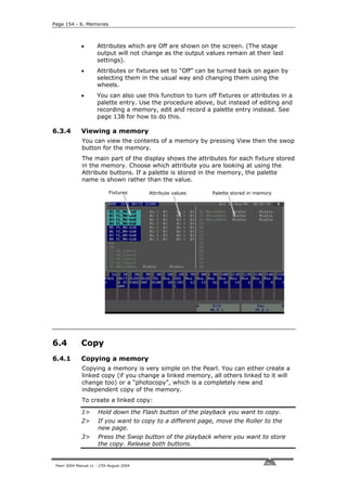
![6. Memories - Page 155
• To create a Photocopy, press the blue Photocopy button before
pressing the playback Flash button
• If you have named the memory you copied, the linked memory
will have the same name, as will a photocopied memory.
6.5 Delete
6.5.1 Deleting a memory
To delete a memory:
1> Press the Delete button.
2> Press the Swop button of the memory you want to delete.
3> Press the Swop button again to confirm the delete.
• If the deleted memory is linked to others, the linked memories are
not affected.
6.6 Timing
6.6.1 Setting fade times for a memory
You can set a fade in and fade out time independently for every
memory. The fades only affect HTP (intensity) channels. There is a
separate LTP timer which allows you to set movement times. LTP
channels which were set to “instant” during Patching (see page 121)
ignore LTP fade times.
1> Press C [Edit Times].
2> Press the Swop button of the playback you want to set times for
3> Press Softkey C to set the fade in time, Softkey D to set the fade
out time, or Softkey E to set the LTP fade time (Options A, B, and
F have no effect on memories and are only used on chases)
4> Type the new time using the numeric keypad and press Enter to
save it.
5> Softkey G sets the memory mode of the chase to 0, 1 or 2
(described below).
6> Press Enter to save the changes. If you press Exit, any times you
have set will be abandoned.
Pearl 2004 Manual v1 - 27th August 2004](https://image.slidesharecdn.com/pearl2004man270804-100221092248-phpapp02/85/Pearl2004-Man270804-127-320.jpg)
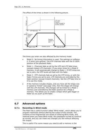
![7. Chases - Page 157
middle of a show without upsetting the current lighting state.
Obviously, as you can’t see the changes you are making, you will need
to have a good idea of what values to set.
1> Hold down AVO and press F [Blind Mode].
2> If you don’t want to use the contents of the programmer, press
Clear.
3> Make changes to your fixtures as usual. Use the screen or the
Graphics Tablet to help you set the right positions, colours etc.
4> Save your changes as usual.
5> To go back to normal, hold down AVO and press Softkey F again.
The previous contents of the programmer will be restored (the
contents of the programmer from Blind mode will be lost).
• If you have edited a playback which is already turned on, you will
need to turn it off then on again to load the new version.
C H A P T E R S E V E N
7. Chases
This chapter contains: Programming a chase; running a chase; setting
speed, crossfade and direction; manually controlling the chase steps;
setting step times and unlinking; editing a chase using unfold; editing a
chase which is running; copying chases; sound activation of chases;
chase options.
As well as being used to store static memories, the playback faders on
the Pearl can also be used to store chases (sequences of static
memories).
7.1 Create
7.1.1 Programming a chase
To program a chase, you have to set up the lighting for each step of the
chase, then save it. The contents of the programmer are recorded as a
step.
You can either set all the fixtures and dimmers manually for each step,
or you can use Include to load in the information from memories you
have already recorded.
You cannot use an existing memory as a chase step just by turning it
on. You need to use the Include button to load the memory into the
programmer.
1> Press the Chase button.
2> Press the Swop button of the playback where you want to store
the chase.
3> Set up the lighting for the first step, either manually or by using
Pearl 2004 Manual v1 - 27th August 2004](https://image.slidesharecdn.com/pearl2004man270804-100221092248-phpapp02/85/Pearl2004-Man270804-129-320.jpg)
![Page 158 - 7. Chases
“Include” on existing memories.
4> Press the Swop button of the playback or Enter to store the
programmer contents as Step 1 of the chase.
5> Press Clear (unless you want to re-use the contents of the
programmer), then repeat from step 3.
6> Press Chase to finish when you have stored all the steps you
want.
• Press Clear when you have finished saving the chase, otherwise
when you try to play it back the programmer will override the
chase and you won’t see the chase properly.
• The current step number is displayed in the prompt line.
• From the July 2004 software version, you can record shapes in a
chase. If the same shape is saved in subsequent steps it will
continue from step to step, if not it will stop at the end of the step
time. (The Pearl considers the shape to be the same if you didn’t
press Clear after the previous step, and didn’t change the speed,
size or spread of the shape from the previous step; or if you
Included the shape from the previous step and have not modified
it)
• You can set a label for the chase by holding down AVO and
pressing G [Set Legend], then pressing the Swop button for the
chase, as with memories.
• There is no limit to the number of steps in a chase provided there
is enough free memory in the Pearl.
7.2 Playback
7.2.1 Running a chase
To run a chase, raise the fader of the playback. Wait timer Fade timer
(You can also use the Flash/Swop buttons if you
are in Normal Run mode). The chase will start to
run.
• The HTP (intensity) channels in the chase
will be controlled by the fader. The other
channels (LTP) will be set as soon as the
fader moves above zero according to the
LTP fade times programmed in the chase.
You can set the point at which the LTP
channels activate from the User settings Step time Crossfade
menu.
• The bottom part of the display shows the progress of the chase.
The Wait and Fade times are represented by bar graphs. The top
line represents the Fade in time; the middle line the Fade Out time
and the bottom line the LTP fade.
• Press View then Connect to show details of the chase steps on the
screen (this screen is described in the Timings section on page
163).
• When in Run mode, you can preload the first step of the chase by
pressing the Flash button of the playback with the Add/Flash
Pearl 2004 Manual v1 - 27th August 2004](https://image.slidesharecdn.com/pearl2004man270804-100221092248-phpapp02/85/Pearl2004-Man270804-130-320.jpg)
![7. Chases - Page 159
Master at zero.
There are many options you can set to determine the way the chase
runs and these are described in the rest of this chapter.
7.2.2 Connecting a chase to the controls
When you run a chase, the playback controls are automatically
connected to it. If you turn on a second chase, the controls are
connected to the newer chase.
• You can choose which chase is connected to the controls by
pressing the Connect button (next to the wheels), then the swop
button for the chase you want to control.
• You can turn off the “chase autoconnect” option in the User
Settings menu (hold down AVO and press C, then set Option 4) if
you don’t want the wheels to connect to a chase when you start it.
You will have to use the Connect button to control the chase if you
do this.
7.2.3 Setting speed, crossfade and direction
The wheels are normally assigned to control the Speed and Crossfade
of the chase when you turn it on.
You can save a speed with the chase, so that every time you play it
back, it runs at the same speed.
1> Press A [Chase Parameters].
2> Set the speed you want using the left hand wheel.
3> Press A [Save Speed].
• If you are in Run mode, you can also set the chase speed by
tapping G [Tap twice to set speed] in time with the music.
• You can change the speed display to BPM (beats per minute)
rather than seconds, from the User Settings menu (see page 196).
• If you are doing another operation using the wheels while running
a chase (e.g. manually positioning some fixtures), you can make
the wheels control speed and crossfade again by pressing the
Connect button next to the wheels, then the swop button for the
chase.
• You can set the chase back to its programmed speed by pressing
Connect, then A [Clear temporary speed].
The chase direction is controlled by the (backwards), (forwards)
and (Bounce) buttons. These buttons can also be assigned as
Fixture control buttons (see page 127). Hold down the Avo button and
press Softkey B so the display shows [Chase Control Enabled] to use
the buttons to control the chase direction.
• You can save the current direction of the chase so it will always
start in that direction; Press A [Chase Parameters], then B [Save
Direction].
7.2.4 Manually controlling the chase steps
You can take manual control over the connected chase by pressing the
Stop button. If the chase is set to “Links Off”, it will do this
automatically - see the next section for details on Links.
Pearl 2004 Manual v1 - 27th August 2004](https://image.slidesharecdn.com/pearl2004man270804-100221092248-phpapp02/85/Pearl2004-Man270804-131-320.jpg)
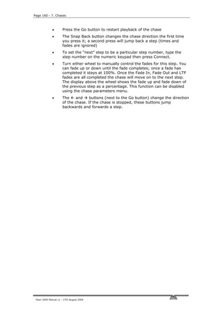
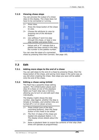
![Page 162 - 7. Chases
4> Various Unfold options are available, the details are below.
5> Press Unfold again to get out of unfold mode.
• To edit the contents of a step: Press Clear to empty the
programmer, raise the fader to output the step, make the
changes, press A [Record], then the Swop button (1-15) for the
step number.
• To change the times for the step, press B [Edit Times], then the
flash button for the step, then set the times (see Timing on the
following page)
• To Insert a new step, set up the lights for the new step, press C
[Insert], then the Swop button where you want to insert the new
step. The new step will be allocated to the button you press with a
step number half way between the steps either side, and all other
steps will be shifted along one. (You cannot use the blue Insert
button in Unfold mode).
• To Delete a step, press D [Delete] then the Swop button for the
step you want to delete, followed by Enter.
• You can copy a step by holding the Flash button of the step to
copy, then pressing the Swop button of the step to copy it to.
• You can renumber the chase to whole numbers by pressing C
[Insert], A [Renumber], then Enter to confirm.
• If the chase has more than 15 steps, you can swap to the next 15
steps using softkey F, or the previous 15 steps using softkey E.
• G [Shape Generator] allows you to insert and edit shapes in the
chase steps.
7.3.3 Editing a chase which is running
You can also edit chase steps while you are running the chase, without
using Unfold. Make sure the step you are editing is not in the middle of
a fade, or you might get unexpected results next time you run the
chase.
1> Start the chase by raising the fader. (if Links are On, press the
Stop button to pause the chase)
2> Keep pressing the Stop button to step on to the step you want, or
type the step number you want, press Connect then Stop.
3> Press Clear to make sure the programmer is empty.
4> Make the changes that you want to the current step.
5> Press Rec. Step, then Enter, to save the changes to the step.
6> Press the Stop button to Pause the chase, then press Next or Prev
to move through steps of the chase.
• You can set individual times for each step using the Live Time
button as follows:
1> Stop the chase on the step you want to set, as above.
2> Press the Live Time button to set the times for the current step,
or the Next Time button for the next step. The Live and Next step
numbers are shown on the display.
3> Use softkeys A-G to set the times you want (see page 155 for
Pearl 2004 Manual v1 - 27th August 2004](https://image.slidesharecdn.com/pearl2004man270804-100221092248-phpapp02/85/Pearl2004-Man270804-134-320.jpg)
![7. Chases - Page 163
description of the times)
4> Press Enter to save the settings, Exit to abandon them, or the ML
Menu button to toggle the step mode between Simple/Complex
(Simple = use the global timings).
5> Press the Stop button to Pause the chase then press Next or Prev
to move through steps of the chase. .
• The Review button shows you the step you have just edited,
including all the fades. When you press Review, the chase jumps
back to the step before the one you are on, then runs the step you
have edited to show you the overall result. The chase does not
have to be stopped to use Review.
• To insert a new step at the current point in the chase: Set up the
lights how you want them for the new step, then press the blue
Insert button, then press Enter. (If you want to insert a different
step number, type it before pressing Enter). The Set Times menu
is displayed. Change the times if you want to, then press Enter to
insert the step.
7.4 Copy
7.4.1 Copying chases
You can copy a chase exactly the same as a memory – hold down the
Flash button of the chase you want to copy, then press the Swop
button of the playback you want to copy it to. The copied chase will be
linked to the original, and any changes made to either chase will affect
both chases.
If you want an unlinked copy, press the Photocopy button before
starting the copy.
7.5 Delete
7.5.1 Deleting chases
You can delete a chase exactly the same as a memory. Press the blue
Delete button, then press the Swop button of the playback containing
the chase. Press the swop button again to confirm the delete.
7.5.2 Deleting a step from a chase
You can delete a step from the connected chase by pressing the blue
Delete button, typing the step number to be deleted, pressing Enter
then A [Yes].
You can also delete a step when a chase is Unfolded by pressing D
[Delete] then the Swop button for the step you want to delete.
7.6 Timing
7.6.1 Speed and crossfade controlled by wheels
Pearl 2004 Manual v1 - 27th August 2004](https://image.slidesharecdn.com/pearl2004man270804-100221092248-phpapp02/85/Pearl2004-Man270804-135-320.jpg)
![Page 164 - 7. Chases
The speed and crossfade of the most recently turned on chase is
controlled by the wheels. You can “connect” the wheels to a different
chase by pressing the Connect button and then the Swop button of the
chase you want to connect.
7.6.2 Setting global step or fade times and unlinking
You can set step times globally for the whole chase and individually for
each step. You can also unlink the steps, either for the whole chase or
for individual steps, so that the chase pauses and waits for you to press
the Go button. This can be useful if you are using the console for
theatrical lighting cues (although it’s easier to use the dedicated
theatrical mode for this).
To set the global times for a chase:
1> Press C [Edit Times], then the playback button for the chase.
2> Press Softkey A-F to select the time parameter to set (the times
are described below).
3> Type the new time value using the numeric keypad and press
Enter
4> Press G to set Link on or off for the whole chase. If link is on the
chase runs automatically. If off, you run each step manually using
the Go button (a chase like this is called a “stack”).
5> Press Enter when you have finished. If you press Exit, any
changes you have made will be lost.
The times are:
A [Wait In] - Delay before the fade in starts
B [Wait Out] - Delay before the fade out starts
C [Fade In] - Time to fade in
D [Fade Out] - Time to fade out
E [LTP Fade] - Time for the LTP (movement) channels to fade over
F [LTP Wait] - Delay before the LTP channels start to move
• You can enter minutes as part of the time - press the decimal
point twice, a colon (:) will appear. e.g. to enter 20 mins 10.5
seconds, type 20..10.5 (the display will show 20:10.5).
Pearl 2004 Manual v1 - 27th August 2004](https://image.slidesharecdn.com/pearl2004man270804-100221092248-phpapp02/85/Pearl2004-Man270804-136-320.jpg)
![7. Chases - Page 165
7.6.3 Setting times and links for individual steps
You can set the fade in and fade out times independently for each
step/cue. Chase steps with individual times are called Complex steps, if
they use the global settings they are called Simple steps. To set
independent times it’s easiest to use Unfold, but you can also stop the
chase and use the Live Time button as described on page 162.
1> Press Unfold then the playback swop button for the chase.
2> Press B [Edit Times], then the playback swop button for the chase
step you want to set
3> Press Softkey A-F to select the time parameter to set, and type
the time value (as described above).
4> Press G to set Link on or off
5> Press Enter when you have finished. If you press Exit, any
changes you have made will be lost.
• Any changes you make will automatically change the step to a
Complex step.
• If you want to return the step to be a Simple step, using the
global times and link settings, press the ML Menu button while in
the Edit Times screen until that the display top line shows “<ML>
Save as Simple” (you may have to press it twice), then press
Enter. Any times you have set will be deleted.
7.6.4 Viewing timing information
You can view the timing settings of a
connected chase by pressing View then
Connect. (when View is set to LCD views;
if the top line of the display shows “VDU
views” when you press View, press G
[LCD views])
For each step, the first line shows the
step number, whether links are off or on
for that step (Off=”-”, On=down arrow),
and whether the step is Simple (S) or
Complex (C).
The second line shows the Wait In, Wait
Out and LTP Wait times for the step.
The third line shows the Fade In, Fade
Out and LTP fade times for the step.
The active step is always at the top of the list, and the list moves up as
the chase runs.
A similar display can be shown on the VDU screen by pressing View,
then G [VDU views]
then Connect. “Wait In” progress
At all times when a Next step number
chase is running, the Chase number
bottom of the screen
shows bargraphs Current step number
LTP Wait progress “Wait Out” progress
Pearl 2004 Manual v1 - 27th August 2004](https://image.slidesharecdn.com/pearl2004man270804-100221092248-phpapp02/85/Pearl2004-Man270804-137-320.jpg)
![Page 166 - 7. Chases
“Fade In” progress
which show the progress of the wait and
fade times.
The left hand section of the bargraphs
shows the Wait timers. The right hand
section shows the Fade timers.
To the left of the bargraphs are numbers
which give the wait or fade progress as a LTP fade progress “Fade Out” progress
countdown from 9 to 0.
The bottom left of the VDU screen shows similar bargraphs when a
chase is running. The
Wait timers Fade timers progress %
progress figures are to the
right of the bargraphs and
are given as a 99 to 00
countdown. “N” is the next
step and “L” is the live step.
7.6.5 Sound activation of chases
The Pearl can use bass, mid or treble frequencies from its audio input
to trigger chases. You can select whether the chase will step on low
frequencies, mid frequencies or high frequencies.
1> Turn on the chase (or Connect it) and press A [Chase parameters]
2> Press E [Sound to Light] to select Low, Mid or High trigger.
3> Turn the key to Run mode and press E [Enable sound to light]
(this is the global Sound to Light enable).
3> When the chase is turned on, it will step in time to the sound
signal
4> Press E, again, to turn off sound activation.
• Turn the chase links Off and set fade times to zero to get a true
sound to light chase.
• You can make some linked steps and some unlinked steps to give
a chase which runs on a few steps for every audio pulse.
• The sensitivity of the audio input can be set using an internal PCB
jumper to enable use of a microphone rather than line level audio.
See page 110.
7.7 Advanced options
7.7.1 Chase options
Each chase has options which can be set to affect the way it runs. Press
A [Chase Parameters]. You need to have a chase “connected”, or the
softkey will not do anything. The options you set are individual for each
chase.
The options are:
A [Save Speed] - saves the current speed of the chase (set using the
left hand wheel)
Pearl 2004 Manual v1 - 27th August 2004](https://image.slidesharecdn.com/pearl2004man270804-100221092248-phpapp02/85/Pearl2004-Man270804-138-320.jpg)
![7. Chases - Page 167
B [Save Direction] - save the direction of the chase (set using the
direction / bounce buttons or options, see below)
C [Normal / Random] - turn on random mode (steps are executed in
random order) - press to change the mode. Turn off random mode
when editing a chase, or you won’t know which step you are going
to get next.
D [Stop on final step] - makes the chase stop on the final step. If the
final step is a blackout, the chase will appear to turn itself off, so
you can just press Go whenever you want to make it happen again
E [Sound to light] – as described above
F [More…] – Gives a second screen of options
A [Fader start options] - (press the button to cycle through the
options):
Fader will reload chase (every time you turn on the chase it starts at
step 1)
Fader stops, go to start chase (the chase will not run until you have
pressed Go after you turn on the chase)
Fader stops/starts chase (every time you turn on the chase it continues
from where it left off)
B [Skip times options] – Allows you to skip the first wait and/or fade
of a chase. You often want to do this so the chase starts as soon as
you raise the fader. (Press the button to cycle through options)…
Skip first wait time (The wait time is missed when the chase is first
turned on)
Skip first wait and fade time (Both wait and fade times are missed
when the chase is first turned on)
Wait and Fade for all steps
C [Manual mode allowed / disallowed] – If set to Allowed, lets you
manually fade a paused step by turning the left hand wheel for the
HTP channels and the right hand wheel for the LTP channels.
D [Speed wheel allowed / disallowed] - Lets you change the chase
speed using the left hand wheel. You might want to turn this off if
you don’t want the console operator to be able to change chase
speeds at playback time.
E [Takeover after Go] - If this option is Disabled, when you have a
chase waiting for the Go button, and you turn on a memory, the
LTP channels will change to those set in the memory. When you
press the Go button, the LTP channels will remain set as in the
memory and will not update to the settings in the chase step.
When the option is enabled, the LTP channels will update to the
settings in the chase step when you press Go.
For example, you are about to press Go to set some fixtures to
Red. You turn on a memory, which sets the same fixtures to Blue.
If the Takeover After Go option is enabled, then pressing Go will
set the fixtures to Red, otherwise the fixtures will remain in Blue.
Pearl 2004 Manual v1 - 27th August 2004](https://image.slidesharecdn.com/pearl2004man270804-100221092248-phpapp02/85/Pearl2004-Man270804-139-320.jpg)
![Page 168 - 8. Theatre stack
C H A P T E R E I G H T
8. Theatre stack
This chapter contains: Setting theatre mode; theatre controls; plotting
a cue; naming a cue; setting fade times; jumping to a cue; running a
theatrical show; advanced options.
Theatre mode allows you to use the Pearl like a standard theatrical
console, where you program your show as a sequence of cues, then run
the show just by pressing the Go button at the appropriate moment.
Playback faders 12-15 become dedicated cue masters.
8.1 Create
8.1.1 Setting theatre stack mode
In program mode, press B [Theatre stack programming]. The Pearl
displays the theatre mode startup display. Press Enter to start.
• When theatre mode is enabled, you can’t access playbacks 12-15
on any page; if you intend to use Theatre mode it is advisable not
to program these playbacks. Any programs are kept and when you
turn off Theatre mode you will be able to access them again.
Chase Autoconnect mode is disabled when theatre mode is turned
on; the theatre stack is always connected to the controls.
• To get out of the theatre menu, press G [Quit]. The Exit button is
disabled in the theatre menu. This does not turn off theatre mode,
but allows you to use the rest of the console.
• To turn off theatre mode completely, at the main menu (not the
Theatre menu) press B [Theatre stack programming], then press
D [Exit Theatre Programming].
• Theatre mode programming is not deleted when theatre mode is
turned off.
• While theatre mode is enabled, the swop button for Playback 12
will flash when the playback fader is at zero.
8.1.2 Theatre controls
While theatre mode is turned on, Playback faders 12-15 have special
functions assigned to them.
Fader 12 is the Master fader, controlling the overall intensity of all
lights.
Fader 13 controls the Fade In of the next step, when it is stopped.
Fader 14 controls the Fade Out of the previous step, when it is stopped.
Faders 13 and 14 operate as crossfaders.
Fader 15 controls the LTP fade timer, when it is stopped.
The Swop and Flash buttons above 13, 14 and 15 are Stop and Go
buttons for each of these functions.
Pearl 2004 Manual v1 - 27th August 2004](https://image.slidesharecdn.com/pearl2004man270804-100221092248-phpapp02/85/Pearl2004-Man270804-140-320.jpg)
![8. Theatre stack - Page 169
8.1.3 Plotting a cue
Plotting a cue is very similar to saving a memory. You need to be in
Program mode to record cues.
The Pearl refers to cues as “Steps”.
1> If you are not already in “Theatre mode” press B [Theatre Stack
Programming] at the main menu.
2> Press Clear to make sure the programmer is empty.
3> Set up the cue, either using the preset faders or typing in the
levels for each channel (see page 129). You can also select
fixtures and use the wheels and attribute buttons to set up the
cue.
4> If the current step number on the display is different to the one
you want to use, type the step (cue) number
5> Press D [Record], then B [Record Stage] to record the current
output of the console, or D [Record programmer] to just record
what you have changed in step 3.
6> If there are no steps, the Pearl will ask for the number of the first
step. Type 1 and press Enter.
7> Press Clear.
8> Repeat from 3 to plot more cues.
• The Pearl will automatically allocate whole numbered cue numbers
as you save cues. You can number cues 1.1, 1.2 and so on, this
allows you to insert up to 9 cues in between existing cues without
changing the numbers.
• The top line of the display shows the Current Step number. This is
the step (cue) which will be used for recording or editing. If you
type in a step number this is shown as the Input Step.
• Softkey A [Record Mode] sets the console to Record By Fixture or
Record by Channel. This is described on page 147.
• B [Record Stage] will record the whole output of the console, as
you see it. This is useful if you want the cue to represent exactly
what’s on the stage. D [Record Programmer] will record only what
you have changed since you last pressed Clear.
• You can use an existing memory to form a cue by either using
Include (see page 152) or, if you only want dimmer levels, just
turn the memory on and use the [Record Stage] option.
• Cues can include moving light positions and shapes. Use softkey B
to set up shapes (see page 141), and use D [Record Programmer]
in the record menu to record it in the cue (if you use B [Record
Stage] the shape will not be recorded). The shape will stop when
the next cue starts, unless it is also recorded (unchanged) in the
next cue.
• The cues you have saved are displayed on the VDU screen. You
can also display them on the LCD screen by pressing View then
Connect (next to the wheels) .
• If you want to run a chase from a cue, you can use an Autoload to
do this (see section 8.4)
Pearl 2004 Manual v1 - 27th August 2004](https://image.slidesharecdn.com/pearl2004man270804-100221092248-phpapp02/85/Pearl2004-Man270804-141-320.jpg)
![Page 170 - 8. Theatre stack
8.1.4 Running a chase or memory with a cue (Autoload)
If you want to run a chase as part of a cue, or automatically turn on an
existing memory, you can assign an Autoload to the step.
Autoloads can either turn on or turn off a playback. A Fade Up autoload
will turn on a playback, a Fade Down autoload will turn it off.
1> Press A [Advanced].
2> Press B [Assign a fade up autoload] or C [Assign a fade down
autoload]
3> Press the Swop button of the playback to be turned on (or off).
The playback will turn on when the cue runs and will remain turned on
until a Fade Down autoload turns it off.
• Each cue can have only one autoload, either a fade up or a fade
down.
• The memory to load can be from any page, but it will be loaded
into the same playback number that it is saved in. If this playback
is active on the current page, it will be turned off and replaced by
the autoload memory.
• Autoloads are shown on the right hand side of the VDU screen. A
fade up autoload has an up arrow, a fade down autoload has a
down arrow.
• You can set a fade time for the autoload using D [Set autoload
fade time]. Type the fade time then press Enter. Fade times only
work to the nearest second.
• You can delete the autoload from the current cue by pressing E
[Delete Autoload] then pressing Enter.
8.1.5 Naming a cue
Type the step number to be named, then press E [Set Legend]. Enter
the legend on the QWERTY keyboard. While you are typing, the input is
shown on the VDU screen.
The name of the live cue and the next cue is displayed in the cue list on
the VDU screen.
8.2 Timing
8.2.1 Setting fade times for a cue
Each cue can be programmed to have its own Fade In and Fade Out
times. You can also set a separate fade time for LTP (movement)
channels in the cue, and you can set wait times to delay the start of the
fade.
Press C [Set Times] to set the timing for the current step/cue. To set
the times for a different cue, type the cue number before pressing C
[Set Times]. to show the options.
You can also press the Live Time button (next to the wheels) to set the
times for the current step.
1> Press Softkey A-F to select the time parameter to set (the times
are described below).
Pearl 2004 Manual v1 - 27th August 2004](https://image.slidesharecdn.com/pearl2004man270804-100221092248-phpapp02/85/Pearl2004-Man270804-142-320.jpg)
![8. Theatre stack - Page 171
2> Type the new time value using the numeric keypad and press
Enter
3> Press G to set Link on or off. If link is On the next cue will run
automatically after the Wait Out time. If off, you run each step
manually using the Go button.
4> Press Enter when you have finished. If you press Exit, any
changes you have made will be lost.
The times are:
A [Wait In] - Delay (after you press Go) before the fade in starts
B [Wait Out] - Delay (after you press Go for the next cue) before this
cue starts to fade out
C [Fade In] - Time to fade in
D [Fade Out] - Time to fade out
E [LTP Fade] - Time for the LTP (movement) channels to fade over
F [LTP Wait] - Delay before the LTP channels start to move
• Links are set to OFF by default, so that you press the Go button
for each cue. If you set links to On for a cue, the next cue will run
automatically after the “Wait Out” time.
• You can enter minutes as part of the time - press the decimal
point twice, a colon (:) will appear. e.g. to enter 20 mins 10.5
seconds, type 20..10.5 (the display
will show 20:10.5).
8.2.2 Displaying the cue timings
Press View then Connect to display the
cue timings on the LCD screen. When you
are in theatre mode, the cue timings are
permanently displayed on the VDU
screen.
The list of cues automatically moves so
that the current step is at the top.
For each step, the first line shows the step
number, whether links are off or on for
that step (Off=”-”, On=down arrow), and
whether the step is Simple (S) or Complex
(C) (theatre stack steps are always
Complex.)
The second line shows the Wait In, Wait Out and LTP Wait times for the
step.
The third line shows the Fade In, Fade Out and LTP fade times for the
step.
Pearl 2004 Manual v1 - 27th August 2004](https://image.slidesharecdn.com/pearl2004man270804-100221092248-phpapp02/85/Pearl2004-Man270804-143-320.jpg)
![Page 172 - 8. Theatre stack
8.3 Playback
8.3.1 Running a theatrical show
If you have just been editing, you may need to type 1 then F [Cut to
Live] to set the console to cue 1. You should also turn the key to “Run”
to make sure you can’t accidentally change anything.
The LCD display shows the
In HTP fade Out HTP fade
current (live) cue/step and the
next cue/step numbers. To the
right of this, bargraphs show
the progress of the fades (see
page 165 for more detail on the next step
bargraphs).
live step
The VDU screen shows a list of
the cues with legends if you
have entered them. The
current cue is highlighted with
LTP fade
a grey background and bright
lettering. The next cue is highlighted in light blue.
For automatic cues, you can simply press the Go button next to the
wheels. The console will carry out the fade with the times you
programmed.
If you want to manually control a fade, you can use the in, out and LTP
faders (13, 14 and 15) or Go/Stop buttons to operate the cue. The
display shows the percentage of fade left to go. When the fade is
completed for that fader, the display shows “0”. When Fade In, Fade
Out and LTP all show “0”, the console moves on to the next cue. (The
picture above shows the in, out and LTP fade displays all at halfway, or
“5”)
Once the display shows “0” you cannot reverse the fade using the
fader.
• You can jump to a step by typing the step number on the keypad
then pressing Connect (next to the wheels). The cue is loaded but
does not start until you press the Go button.
Pearl 2004 Manual v1 - 27th August 2004](https://image.slidesharecdn.com/pearl2004man270804-100221092248-phpapp02/85/Pearl2004-Man270804-144-320.jpg)
![8. Theatre stack - Page 173
• When the Add/Flash master is at zero, the Theatre Stack Go
function of the playback Flash buttons is disabled. When the Swop
master is at zero, the Stop function of the blue playback swop
buttons is disabled.
8.4 Edit
8.4.1 Editing a cue
You can edit a cue you have saved as follows:
1> Press Clear.
2> Ensure the Dimmer attribute is selected.
3> Press Include (above the numeric keypad)
4> Press E [Include Theatre Stack Step]
5> Type the step number to be edited and press Enter.
6> Make the changes you want using the preset faders or by entering
new levels.
7> Press D [Record], then D [Record programmer].
8> Press Clear to clear the programmer. The cue will be updated.
8.4.2 Jumping to a cue
You can change the cue being edited by typing the cue number then
pressing Enter. If you want to output this cue, press F [Cut to Live]
(fade times are ignored).
8.4.3 Inserting a cue
You can insert a cue between two existing cues by typing a cue number
in between the two existing cues when saving the step.
8.4.4 Renumbering cues
Press A [Advanced] then A [Renumber], then F [Yes], to renumber all
the steps to whole numbers.
8.4.5 Copying a cue
Press A [Advanced] then F [Copy current step to…], type the number
for the new cue and press Enter.
8.5 Delete
8.5.1 Deleting a cue
Press the blue Delete button, then type the step number to be deleted
and press Enter.
You can delete all steps by pressing A [Delete All Steps].
Pearl 2004 Manual v1 - 27th August 2004](https://image.slidesharecdn.com/pearl2004man270804-100221092248-phpapp02/85/Pearl2004-Man270804-145-320.jpg)
![Page 174 - 8. Theatre stack
8.6 Advanced options
8.6.1 Advanced theatre options
Press A [Advanced] to display the Advanced theatre options menu.
The options are:
A [Renumber] – Renumbers all cues to whole numbers.
B [Assign a fade up autoload] – Assigns a memory or chase which
will be automatically loaded and run when the fade-in for the cue
starts.
C [Assign a fade down autoload] – Allows you to turn off a memory
or chase when the cue starts.
D [Set autoload fade time] – Allows you to set a fade time for the
autoload.
E [Delete autoload] – Deletes the autoload memory from the current
cue.
F [Copy current step to…] – Allows you to copy the current step to a
new step.
Pearl 2004 Manual v1 - 27th August 2004](https://image.slidesharecdn.com/pearl2004man270804-100221092248-phpapp02/85/Pearl2004-Man270804-146-320.jpg)
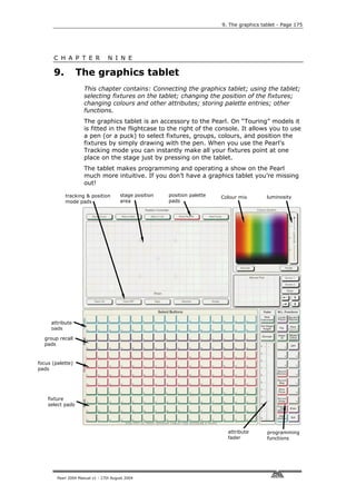
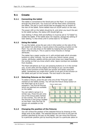
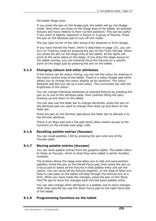
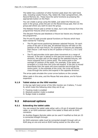

![Page 180 - 10. Running the show
C H A P T E R T E N
10. Running the show
This chapter contains: Run modes, channel mimics, master faders,
manual control during a show
10.1 Playback
10.1.1 Run modes
When you finish programming, back up the console to disk before you
start the show (see page 194). Then turn the key to Run mode to make
sure you can’t accidentally change anything.
When you are running a show, there are two modes available to you,
normal Run mode, where you can turn on anything you have
programmed but can’t control anything manually, and Takeover run
mode which allows you to take manual control if you want. The mode
also affects how the Swop and Flash buttons on the console operate.
There is also “2 preset mode” which you have to enable in the User
Settings menu, see section 10.2.
You can select the mode by pressing A [Toggle mode]. The mode is
shown on the top line of the display.
• Normal Run mode: the Flash and Swop buttons on the handles
and playbacks work as flash buttons. The “Flash” button adds the
function into anything else which is on. The “Swop” button turns
on the function, but turns off everything else while the button is
held down. The programmer is cleared and you can’t manually
control any LTP channels. You can control HTP channels using the
preset faders.
• Takeover run mode: the Swop buttons on the handles allow you
to select dimmers or fixtures for manual control. This lets you add
to or change your programming in real time during the show. The
Flash buttons on the handles recall palette values (but unless you
are used to the Pearl, it is easier to use the dedicated Palette
buttons). The faders still control the intensity of the dimmers and
fixtures. The Flash and Swop buttons on the playbacks are
disabled.
10.1.2 Master faders
In the bottom left hand corner of the console are the Master Faders.
These allow overall intensity control of the whole console.
• The Add/Flash and Swop masters control the intensity of the Flash and
Swop buttons on the playbacks. This allows you to flash the playbacks
to a certain level. It also allows you to disable the Flash buttons by
setting the master at 0. (If you turn the Swop master to 0 you will get
a blackout if you press a Swop button).
• The Preset Master controls the overall intensity of any channels turned
on in the Preset faders.
• The Grand Master controls the intensity of all output from the console.
Pearl 2004 Manual v1 - 27th August 2004](https://image.slidesharecdn.com/pearl2004man270804-100221092248-phpapp02/85/Pearl2004-Man270804-152-320.jpg)
![10. Running the show - Page 181
Normally you would set this at full, and use it if you need to quickly
fade out all the lights.
10.1.3 Manual control during a show (“Busking”)
If you have not had as much programming time as you would have
liked, you might need to make up some additional effects during the
show. Fortunately the Pearl is designed with this in mind and there are
lots of features to spice up your life. You need to be in Takeover Run
mode to do this stuff.
Instant palettes: Select some fixtures, press Focus, then select a
palette option from the softkeys (or press a grey Flash/Palette button).
When you recall a palette value instantly, it gets placed in the
programmer. This means that the palette will override any memories
you later turn on, until you press “Clear”.
Fading palettes: You can “fade” to a palette value by selecting the
fixtures you want to change, typing the fade time (e.g. “2” for 2
seconds), pressing Focus, then using the softkey menus to recall the
Palette you want (e.g. Green). The selected fixtures will change to
Green over a 2 second period. If you fade to a palette value, the palette
does not go into the programmer. This means that when you turn on a
new memory, the fixtures will change to the new memory rather than
being overridden by the palette.
Palette master time: You can set a Master Time option in the Palette
Options so that all palettes will fade without you having to type in a
time. Press Focus, then G [Options], then A [Master Time]. Type a new
time and press Enter. If you want instant palettes that don’t get put in
the programmer, you can set the master time to 0.1 seconds.
Changing all fixtures in a memory: You can apply a “quick palette”
to all the fixtures in a memory (without having to select the fixtures) by
pressing Focus, holding down the softkey for the palette you want, then
pressing the Swop button of the memory. If you type a number after
pressing Focus, the palette values will fade over the time you typed.
This palette is not placed in the programmer, so the next LTP changes
will overwrite it. (User Settings option 6 must be turned on for this to
work)
Nudge mode: You can also change the position of fixtures; the easiest
way to do this is to use “Nudge” mode on the graphics tablet. This
allows you to sweep selected fixtures around their programmed position
by drawing with the pen, so you can alter the height of a chase or
shape in real time.
Tracking: If you have trained the desk for Tracking, you can (with
practice!) follow someone on the stage or move fixtures to point to a
soloist.
Manual control: You can control any attribute of a fixture manually
exactly like when you were programming. This requires care to look
good; using the preset palettes is usually a better bet.
You cannot add new shapes in Run mode. You need to have some
shapes saved in memories which you can then turn on.
Pearl 2004 Manual v1 - 27th August 2004](https://image.slidesharecdn.com/pearl2004man270804-100221092248-phpapp02/85/Pearl2004-Man270804-153-320.jpg)
![Page 182 - 10. Running the show
10.2 Options
10.2.1 Two-preset mode
You can use the top and bottom preset faders to control dimmers
patched on the 1-30 faders in a standard “two preset” mode, using the
A and B Masters as preset masters. In this mode, fader 31 controls the
same dimmer as fader 1, fader 32 controls the same as fader 2, and so
on. This allows you to set up two different lighting states and fade
between them using the A and B masters, as you would on a basic
lighting desk.
To enable Two preset mode, set User Setting 1 to “2-preset”. (Hold
AVO and press Softkey C to get the user settings).
In this mode, anything patched to the top faders 31-60 is not
accessible using the faders, however programmed memories and
chases will play back as if in Normal Run mode. The Playback Master
fader is used as the B Master in this mode and does not control
Playback level. All playbacks will run at full level.
10.2.2 Temporarily locking the console
You can temporarily lock the console by typing a 4 digit code then
pressing C [Lock Desk], then Enter. All the controls on the panel will be
disabled. Enter the code again to unlock the console.
This is useful to prevent passers-by or sound engineers tampering with
the console if you need to leave it unattended; it is not secure as you
can simply reset or re-power the console to remove the lock.
10.2.3 Channel mimics
If you are in normal Run mode, the LEDs on each handle mimic the
intensity of the fixture or dimmer controlled by that handle (i.e. they
are lit if it is turned on).
If you are in Takeover Run mode (or Program mode), you can choose
between “Mimic” mode, or “Fixture” mode where the LEDs show you
which fixtures are selected for manual control.
You select the mode by holding down the Avo button and pressing
Softkey A. The button shows “Preset LEDs = Fixtures” (or mimics)
depending on the mode. You can also change this mode using the
Graphics Tablet.
Pearl 2004 Manual v1 - 27th August 2004](https://image.slidesharecdn.com/pearl2004man270804-100221092248-phpapp02/85/Pearl2004-Man270804-154-320.jpg)

![Page 184 - 11. Automated playback (script files)
C H A P T E R E L E V E N
11. Automated playback (script files)
This chapter contains: Script files, using script files in Run mode.
Script files are a powerful feature of the Pearl which allow you to record
a show in real time using the playback faders, then play back the show
automatically, synchronised to an external MIDI time code source, or
using the Pearl’s internal clock. This is very useful for repeated light
shows such as at exhibitions or in fixed displays.
The script file is simply a list of instructions to the Pearl which specify
actions at certain times. The easiest way to make a script file is to get
the Pearl to record your actions as you do them, but you can also enter
commands individually.
11.1 Create
11.1.1 Recording Script files
Before you can create your script file, you need to program all the
memories and chases you want to use.
To enter script file programming mode, turn the key to “System”, then
press D [Script file programming].
The procedure for programming a script file is as follows:
1> Press A [Select timer source], then A [External timecode] (MIDI)
or D [Internal timer].
2> Press B [Record script file]. Start the timecode source if using
MIDI. If using the internal timer, press A [Select timer source]
then F [Start timer] to start it.
3> Run the show as you want it by turning playbacks on and off. The
Pearl records your actions (including fade times) as script file
commands. You must move faders to maximum for the action to
be recorded.
4> Press F [Done] when finished.
• By default the Pearl will record Script File 1. You can change this
using option C [Select script file].
• Press D [Reset Timer] to set the timer back to zero. You can use
this if you want the recording to start at zero; otherwise the timer
runs before you are ready to start recording.
• You can use Time of Day as timecode by pressing C [Clock
Timecode] from the select timer source menu. When recording for
Time of Day playback, it’s easiest to use Internal timer and set the
internal timer to the real time you want to be recorded.
• At any point, pressing the ML Menu button will reset any
playbacks which have been turned on by the script file and move
the file back to the first step.
• Option E [Clear masters] will turn off any playbacks used by the
script file.
• Ensure the master faders are at full when recording Script files
Pearl 2004 Manual v1 - 27th August 2004](https://image.slidesharecdn.com/pearl2004man270804-100221092248-phpapp02/85/Pearl2004-Man270804-156-320.jpg)
![11. Automated playback (script files) - Page 185
otherwise the playback faders will not be recorded.
11.1.2 What is recorded in the script file
The script file records two types of action:
When a playback fader is raised, the script file records
• The playback number, roller segment and roller page number
• The timecode setting when the fader starts to move
• The time taken for the playback fader to move from the trigger
point to full.
When a playback fader is lowered, the script file records
• The playback number
• The timecode setting when the fader starts to move
• The time taken for the playback fader to move from full to the
trigger point.
11.2 Playback
You can play back script files either from script file programming mode
(with the key set to System), or from Run mode. Normally you will test
the script file runs correctly after you’ve programmed it, but then
switch to Run mode to actually use it.
11.2.1 Selecting a script file for testing
The Pearl can play and record script files numbered 1 to 99.
1> If you are not in Script File Programming mode, turn the key to
System and press D [Script file programming].
2> From the script file menu press C [Select script file].
3> Type the script file number on the numeric keypad, or use the up
and down arrows to highlight the script file you want on the
screen.
4> Press Enter.
This will load the script file, but will not run it yet.
• Press F [Next Step] to select the current step in the file. The timer
will change to match the timecode of the step.
• Press ML Menu to make step 1 the active step, and turn off any
playbacks used by the script file.
11.2.2 Testing the script file
It’s easiest to use the internal clock to test the script file, though you
can also restart your external timecode source if you are using one. The
internal clock produces the same type of timecode as the external
(MIDI) timecode.
The display shows the next step to be run with an asterisk (*), and the
live step is shown below the clock as “Live=XX”.
1> Press A [Select timer source]
2> Press D, [Internal timer].
3> If you are simulating an external timecode, type the start time
Pearl 2004 Manual v1 - 27th August 2004](https://image.slidesharecdn.com/pearl2004man270804-100221092248-phpapp02/85/Pearl2004-Man270804-157-320.jpg)
![Page 186 - 11. Automated playback (script files)
using the keypad. Or just press
Enter to set the timer to zero.
4> Press E [Connect Timer] to run the
script file to the timecode.
5> The timer will run and the script file
will replay.
• You can use Time of Day as
timecode by pressing C [Clock
Timecode] from the select timer
source menu. This can be useful if
the Pearl is running time-related
lighting shows.
• You can jump to a step by typing the
step number on the keypad and
pressing Enter. If you are using the
internal clock it will jump to the time
for that step.
• When the script file is running, softkey E becomes [Disconnect
Timer], which will stop the file running. Softkey F becomes
[Synchronise] which will synchronise the script file to the current
timer, skipping steps if necessary.
11.2.3 Using Script files in Run mode
When the Pearl is in Run mode, a special set of Script file options are
available. You can run a script file and operate the console manually at
the same time.
First you need to set the options for the script file.
D [Script file Functions] - Sets options for how the script file is run.
The menu options are:
• A [Select timer source] - Selects external or internal timecode and
starts or stops the internal timer (same as option A on the main
Script File menu)
• C [Select script file] - Allows a script file to be selected (same as
option C on the main Script File menu)
• D [Start from Step 1] - Resets the file to step 1, also resets the
internal timer, if you are using it, to the Step 1 time.
• E [Connect timer] - Runs the script file. (Same as option E on the
main Script File menu). This option changes to [Disconnect timer]
when the script file is connected.
• F [Next Step] - Moves the script file on to the next step, and
outputs the step. Also moves the internal timer on to the time for
the next step. This option changes to [Synchronise] when a script
file is running, which will skip any missed steps.
• G [Clear Script File Playbacks]. Turns off all playbacks which have
been used by the script file.
You can also press ML Menu to release the playbacks which have
been used.
C [Play Script File] - Starts the currently selected Script file (selected
using option D). The script file runs from its current position, so you
may need to reset it to step 1 (see above). If you are using the
Pearl 2004 Manual v1 - 27th August 2004](https://image.slidesharecdn.com/pearl2004man270804-100221092248-phpapp02/85/Pearl2004-Man270804-158-320.jpg)
![11. Automated playback (script files) - Page 187
internal timer, the timer is started.
The option changes to [Pause Script file] when selected.
11.2.4 Looping and running script files on power up
The Pearl can be configured to run script files on power up, and to loop
the script file (if using internal time code). This is useful for unattended
operation in exhibitions.
In the Script file main menu, Press G [Script File parameters] to set
these options.
Select the script file you want to change
using the up and down arrows. The current
script file is highlighted.
Option B [Toggle Loop mode] changes the
Loop setting of the current script file. Loop
resets the timer to zero when the file
finishes (this only works when using the
internal timer). The display shows “Ends”
or “Cont” (continuous)
Option C [Toggle the script file autorun]
changes the Autorun setting for the
current script file. The Auto column will
show “ON” when autorun is enabled. The
Global Autorun setting, option A, must also
be enabled for Autorun to work.
Option A [Toggle the Global Autorun] sets
the global setting which enables or
disables Autoruns. The top line of the display shows “Global Auto=”
status.
11.3 Edit
Press D [Edit a script file].
You can edit each step of a script file to change the playback number,
the timecode value for the step, and the fade in and out time. Timecode
editing is described in the Timing section.
11.3.1 The script file edit display
The screen shows the steps in the script file. The current step is
indicated with an arrow. You can change the current step using the up
and down arrow buttons, or by typing the step number on the keypad.
As there isn’t space to describe the step on the screen, a code is used:
C 1A 12 (Chase on Roller Page 1, roller segment A, playback 12)
M 1C 10 (Memory on Roller Page 1, roller segment C, playback 10)
R 10 (Ramp down (turn off) of playback 10. Page information is not
given for ramp down steps)
The VDU screen, having more space, shows more detail of the steps.
Pearl 2004 Manual v1 - 27th August 2004](https://image.slidesharecdn.com/pearl2004man270804-100221092248-phpapp02/85/Pearl2004-Man270804-159-320.jpg)
![Page 188 - 11. Automated playback (script files)
11.3.2 Editing an action
This allows you to change the playback number, or to set a “ramp
down” for a playback, or to change the fade in/out time.
Select the step to be edited using the up and down arrow keys, then
press D [Assign Action]. The options are:
A [Load]: followed by the swop button of the playback to be loaded.
Changes the step to a fade in of the playback you select.
B [Ramp Down]: followed by the swop button of the playback to turn
off. Changes the step to a fade out of the playback you select.
C [Record a blackout step]: inserts a blackout. All playbacks under
control of the script file are taken to zero.
D [Ramp Time]: sets the fade in/out time. Type the new time in
seconds on the keypad and press Enter.
E [Theatre Stack GO]: sets this step to trigger the Go button on the
theatre stack.
11.3.3 Inserting a step into the script file
Use the arrow keys to select the position for the new step.
Press B [Insert before step x] or C [Insert after step x] to insert the
new step. The new step is blank, with no action or timecode.
Use the Assign Action and Assign Timecode options to set the action
and timecode for the inserted step.
11.3.4 “On-the-fly” editing
Softkey F [On the fly editing] allows you to add new events to the file in
real time as it plays back. (You can also add events to the file while it is
paused, anything you do will be added at the current timer setting).
The options on the menu are:
A [Select timer source] - same as option A on the main menu
C [Sort steps by timecode] - same as option C on the Assign Timecode
menu
D [Play] - runs the file from the current time
E [Pause] - stops running the file
F [Start script file from step 1]
G [On the fly editing] - highlighted when this mode is active. Press to
turn off on-the-fly editing.
11.4 Timing
Press D [Edit a script file] to amend timings.
11.4.1 Editing a timecode
Select the step to be edited using the up and down arrow keys, then
press E [Assign timecode].
To enter a new timecode from the keypad, press C [Assign TC from
Pearl 2004 Manual v1 - 27th August 2004](https://image.slidesharecdn.com/pearl2004man270804-100221092248-phpapp02/85/Pearl2004-Man270804-160-320.jpg)
![11. Automated playback (script files) - Page 189
input], type in the new timecode value on the keypad and press D
[Assign TC to step from input]. Timecode is displayed and entered as
HH/MM/SS.FF (hours, minutes, seconds, frames – frames are 1/25th of
a second). The top line of the display shows you the timecode you are
entering.
Alternatively, press D [Assign TC to step] to use the current timecode
setting.
11.4.2 Changing timecode for a group of steps
If you want to offset the timing of a number of consecutive steps, you
can allocate them to a group and change the start time of the group.
The grouped steps will keep their timings relative to each other, but will
all be offset.
You define the group like this:
1> Press E [Assign Timecode]
2> Use the up and down arrows to select the step to add to the group
3> Press F [Toggle group] to add the step to the group. An arrow “<”
will appear next to the step.
4> Repeat from 2 to add other steps to the group
• All consecutive steps marked “<” are now part of a group.
• Also, other consecutive steps you haven’t marked automatically
become a different group. For example, if you’ve got a file with 30
steps and you mark steps 1-10 as a group, steps 11-30 will
become another group.
A new timecode is assigned to the group like this:
1> Use the up and down arrows to select a step in the group
2> Press E [Assign TC from input], type the timecode where you
want the first step in the group to run, and press C [Assign TC to
group from input].
3> Alternatively press C [Assign TC to group] to use the current
timecode setting.
4> All steps in the group will be offset to the new time, but will keep
their relative timings.
You can also press A [Select a timer source] to select current timecode
to be taken from external or internal clocks.
11.4.3 Changing the start timecode for the whole script file
In the Assign Timecode menu, Softkey B [Assign TC to file start] will
set the current timecode as the new start time for the whole file. All
steps in the script file will keep their relative timings. You can use this
command with the timer stopped or running
To enter a start timecode on the keypad, press E [Assign TC from
input], type in the timecode, then press B [Assign TC to File Start from
input].
11.4.4 Sorting the steps into time order
When you have edited steps, the display may show the steps in the
wrong order. Press E [Assign Timecode] then G [Sort by timecode] to
re-order the display into the correct order. The functioning of the script
Pearl 2004 Manual v1 - 27th August 2004](https://image.slidesharecdn.com/pearl2004man270804-100221092248-phpapp02/85/Pearl2004-Man270804-161-320.jpg)
![Page 190 - 11. Automated playback (script files)
file is not affected.
11.5 Copy
11.5.1 Copying a script file
Press G [Script file parameters].
Select the script file to be copied using the up and down arrow keys.
The current script file is highlighted.
Press the blue Photocopy button.
Type in a number for the newly copied script file.
Press Enter to confirm or exit to cancel.
11.6 Delete
11.6.1 Deleting a step
Press D [Edit a script file].
Select the step to be deleted using the up and down arrow keys, then
press A [Delete Step].
Press F [Yes] to confirm.
11.6.2 Deleting a script file
Press G [Script file parameters].
Select the script file to be deleted using the up and down arrow keys.
The current script file is highlighted.
Press the blue Delete button.
Press Enter to confirm or exit to cancel.
11.7 Options
The options on the Script File Menu are:
A [Select timer source] - Allows you to select the source for the
timer on which the script file is based. The possibilities are:
• A - External (MIDI) time code.
• C - Clock Timecode - uses the Time of Day as the clock
• D - Internal timer /TC - uses the internal clock
• E - Stop timer - stops the internal clock
• F - Start timer - restarts the internal clock
You can enter a setting for the internal clock using the numeric
keypad - 2 digits each for hours, minutes, seconds, frames - then
press Enter. The time you are entering is shown at the bottom of
the screen.
To reset the internal timer to 0, just press Enter.
Pearl 2004 Manual v1 - 27th August 2004](https://image.slidesharecdn.com/pearl2004man270804-100221092248-phpapp02/85/Pearl2004-Man270804-162-320.jpg)
![11. Automated playback (script files) - Page 191
B [Record script file] - This option lets you create a new script file as
described in section 11.1.1. If there is already a script file, the
Pearl will check you want to overwrite it (if not, select No and use
option C below to work on another file).
C [Select script file] - Lets you select which script file you want to
work on. The display shows a list of script files. Type the number
of the one you want using the numeric keypad, from 01-99, then
press Enter. To start with a new blank file, select any number
which is not on the list.
D [Edit script file] - Allows you to edit the current file, described in
detail in the Edit section on page 187.
E [Connect Timer] - Connects the timer to the script file. This will
cause steps to be executed when the event timecode matches the
timer. The option changes to Disconnect timer when selected, and
option F changes to Synchronise.
F [Next Step] - Moves on to the next step in the script file. The timer
is set to match the time of the step and the step is output. This
option changes to Synchronise when the timer is connected to the
script file; this allows the file to “catch up” with the timer by
skipping events.
G [Script File parameters] - Lets you set options for how the script
file is run. The display shows a list of the script files available, you
can select the current file using the cursor arrows or by entering
the script file number on the keypad. The menu options are:
• A [Toggle the Global Autorun] - Enables Autorun, any file with
Autorun turned on using option C will run when the Pearl is
turned on
• B [Toggle Loop mode] - Changes the Loop setting of the
current script file. Loop resets the timer to zero when the file
finishes. Only works with the internal timer.
• C [Toggle the script file autorun] - Changes the Autorun
setting for the current script file. Global Autorun must also be
On. The Auto column will show “ON” when autorun is
enabled.
• D [Set end-time from input] - Allows you to set the end-time
of the file from the numeric keypad
• E [Set end-time from script] - Sets the end-time to the last
event in the file.
Pearl 2004 Manual v1 - 27th August 2004](https://image.slidesharecdn.com/pearl2004man270804-100221092248-phpapp02/85/Pearl2004-Man270804-163-320.jpg)
![Page 192 - 12. Setup
C H A P T E R T W E L V E
12. Setup
This chapter contains: The user settings menu; Wipe modes; Disk
functions
The Pearl is very easy to customise to your preferred way of working.
The main options are contained in the “User settings menu”.
12.1 User Settings
12.1.1 The User Settings menu
This menu is obtained by holding down the AVO button and pressing C
[User Settings]. You can also turn the key to System mode and press C
[User Settings].
You select the option to change using the cursor up/down buttons, and
make the changes using the left/right buttons.
The options are:
1. Normal Run / Take Over - Sets the Run mode of the Pearl. This
option can also be set by pressing Softkey A while in Run mode.
See page 180 for details of Run mode.
2. Rec by Fixture / Rec by channel - Sets the recording mode of the
Pearl. If set to “by Instrument”, if any attributes of a fixture are
changed, all attributes are recorded. If set to “by channel”, only
changed attributes are recorded. See page 147 for details of how
this works. This option can also be set by holding the Avo button
and pressing Softkey B.
3. Speed=Seconds / BPM - Allows you to set whether chase speed is
displayed in Seconds or Beats Per Minute (tempo).
4. Autoconnect Yes / No - Allows you to turn Chase autoconnect on
or off. If on, the controls are automatically connected to the most
recently turned on chase. If off, you have to connect the chase
manually using the Connect button.
5. Palette page Off / On - When set to on, 30 different palettes are
available from the flash buttons on each fixture page (1-30 on
Page 0--, 31-60 on Page 1--, 61-90 on Page 2-- and 91-120 on
Page 3--). When set to Off, palettes 1-30 are on the flash buttons
for all fixture pages.
6. Q palette Off / On - Enables the quick palette function which allows
you to apply a palette to all fixtures if no fixtures are selected
7. G-Tablet / Remote Control / DSR-20 Remote - Specifies what
device is connected to the serial port
8. DMX Chans = xxx - Sets the maximum number of DMX channels to
transmit. If your rig does not use all 512 channels, you can
improve the DMX refresh rate by reducing this number to the
maximum of your rig. You can also set this option from the “Set
DMX Lines” option in Patch mode.
Pearl 2004 Manual v1 - 27th August 2004](https://image.slidesharecdn.com/pearl2004man270804-100221092248-phpapp02/85/Pearl2004-Man270804-164-320.jpg)
![12. Setup - Page 193
9. Fader ON > x (vv) - Sets the level of the fader at which LTP
channels turn on when fading in a memory or chase. X is the
percentage value, vv is the raw DMX value
10. Fader OFF < x (vv) - Sets the level of the fader at which LTP
channels turn off when fading out a memory or chase. This has to
be at least 2 values below the “on” value. The Pearl will not let you
set an incorrect value.
11. Grand Master OK / Broken - Allows you to disable (fix at full) the
Grand Master fader should it happen to get broken by oiks being
careless with the desk case lid.
12. TC Check On / Off – Turns MIDI timecode checking on or off. If
turned on, the Pearl will sample the incoming timecode, and if it is
corrupted will substitute internal timecode until the external
timecode is OK again.
13. xxx mcS - Sets the DMX idle time (the delay between the end of
one packet and the start of the next). This allows you to slow
down the DMX refresh rate if you have some equipment that can’t
keep up. Increasing the delay will degrade the performance of the
DMX link so you should not change this unless you have to. The
figure in brackets shows the DMX refresh rate in milliseconds.
14. Midi - SLAVE/MASTER/DISABLED/Visualiser - Sets the MIDI
mode of the Pearl. In Slave mode it receives data, in Master mode
it transmits data when you press a key or raise a fader. This
provides a simple way of recording a show straight into a
sequencer.
15. Midi channel = xx - Sets the MIDI transmit / receive channel.
MIDI channels are actually numbered 1-16, and the Pearl displays
0-15, so add 1 to the Pearl display to get the actual channel.
16. Use 720K / 1.4Mb disks – Sets which type of disk the Pearl
expects. The Pearl uses this setting to work out if your show will
fit on a single disk, or if it needs to span multiple disks.
There are also options on the softkeys, these are:
A [Fixtures or Mimics] – The Swop button LEDs can show either the
fixture intensity (Mimic) or light up if the fixture is selected
(Fixtures). This option can also be set by holding the Avo button
and pressing Softkey A
B [Set TC valid range] – Allows you to set the MIDI timecode range
which will be accepted. Enter the minimum time as prompted on
the screen and press softkey A, or the maximum time and press
softkey B.
C [Specify Attributes for Bank] - Allows you to set which attributes
go together (also called the Focus Mask, see page 138 for another
way of setting this). Normally the Dimmer attribute includes all
the others, and the Colour attribute includes the
cyan/magenta/yellow attributes, but you can change this. Select
the Attribute to change, then press this option. Select the other
attributes you want to include, then press Exit. Beware of
changing these settings unless you are sure what you are doing.
G [Default settings] - sets all settings back to the defaults.
Pearl 2004 Manual v1 - 27th August 2004](https://image.slidesharecdn.com/pearl2004man270804-100221092248-phpapp02/85/Pearl2004-Man270804-165-320.jpg)
![Page 194 - 12. Setup
12.1.2 Setting the Wheel acceleration
The control wheels allow you to set 16-bit control values to the fixtures,
and have an acceleration function so you don’t have to spin the wheel
for hours if you need to make large changes to the fixtures.
Hold down the AVO button and press the 2 button to set the different
wheel acceleration curves. The current curve is shown on the main part
of the screen. “Linear Fast” has the fastest response and “Linear Slow”
the slowest and most accurate.
12.2 User functions
12.2.1 The Wipe menu
This menu is obtained by turning the key to System mode and then
pressing A [Service]. Softkey F [Wipe] then selects the Wipe menu.
You can selectively wipe various parts of the console, or you can wipe
the whole thing. Press softkeys B, C and D to turn the wipe options on
and off. The option is highlighted when that wipe option is turned on.
The options are:
A [Cancel] - quits Wipe mode
B [Patch] - Sets the Patching to be wiped. The programming and
individual Palettes will also be wiped (as they would mean nothing
without the patch), however shared palettes (see page 135) will
remain.
C [Palettes]- Sets the Palettes (including shared palettes) to be wiped.
D [Programming] - Sets the memories, chases and theatre stack to
be erased. The Patch and palettes (shared and individual) will remain.
F [Wipeall] - Will wipe the whole memory, setting the console back to
factory default state. The settings of the B, C and D options are
ignored.
G [OK] - Will wipe the memory as set by options B, C and D.
12.2.2 Disk functions
Press the Disk button to display the disk menu. The options are:
A [Load show from disk] - The Pearl displays the name of the show
on the disk. This is shown on the VDU screen only. Press Enter to
load it or Exit to cancel.
B [Save show to disk] - Saves the contents of the console to the
disk. Type a name for the show, then press Enter. The Pearl will
ask if you want to make the show compatible with Sep 2000
software. Press softkey B for No or A for Yes (Sound to light
options will be lost if you select Yes).
C [Verify disk] – Compares the show on the disk to the contents of
the Pearl.
D [Format options] - Allows you to format a disk to 720K or 1.44M,
Pearl 2004 Manual v1 - 27th August 2004](https://image.slidesharecdn.com/pearl2004man270804-100221092248-phpapp02/85/Pearl2004-Man270804-166-320.jpg)
![12. Setup - Page 195
then optionally save a show when the format is complete. This is
also a handy way to wipe a disk if you don’t have a blank disk
with you.
E [Catalogue] – Displays (on the VDU screen) the show file on the
disk.
F [Import Chase] – You can import a matrix chase created on an
external PC application using this feature. To import a chase,
insert the disk containing the chase you wish to import and select
this option.
G [Load visualiser CSV file] – You can load a CSV file from Avolites
Visualiser which contains the patch information from the
Visualiser setup, which will patch the console to match the
Visualiser.
Pearl 2004 Manual v1 - 27th August 2004](https://image.slidesharecdn.com/pearl2004man270804-100221092248-phpapp02/85/Pearl2004-Man270804-167-320.jpg)
![Page 196 - 13. Other features
C H A P T E R T H I R T E E N
13. Other features
This chapter contains:Setting the Pearl’s clock & other utility functions;
using MIDI commands with the Pearl; Service mode; hardware
WIPEALL mode.
13.1 System Configuration
13.1.1 Utility menu
The Utility menu is accessed by turning the key to System, then
pressing G [Utilities].
A [Set clock] - The Pearl has a built-in real time clock. It uses this to
record snapshot times and disk backups, so it’s important to have
the correct time and date set on it.
To set the clock you need to be in System mode, and you need to
have a VDU screen connected.
Press A [Set Clock]. The Pearl displays a window on the VDU
screen in which you can enter the time, date and daylight saving
modes (if the clocks get put forward an hour in summer). Press
Exit to abandon or Enter to save.
C [Configure a MIDI keyboard] - Lets you change which MIDI note
turns on each memory. Send the MIDI note for memory 1, then
the note for memory 2, and so on. A prompt is displayed on the
VDU screen which tells you what the Pearl is expecting you to do.
Press Exit to end.
D [Cache personality file] - Lets you load the personality files into
the Pearl, so you don’t need to carry a personality disk around
with you. You need the special compressed personality file called
P2000PER.CMP which is available from the Avolites web site. If
you have created your own personality cache (see page 206) you
use this option to load it.
E [Load shape file] - Allows you to load a new shape definition file
SG.DAT. You may need to do this if Avolites issue an updated
shape file.
F [Clear Wrap around channels] - If you load a show saved with an
earlier version of software, you might get a problem with
channels which wrap around from 255 to 0. Running this option
will sort them out.
G [Update personality] - Allows you to load an updated version of
the personality file for the fixtures you currently have patched.
This is useful if Avolites release an updated version of the
personality, for example adding Range Tables. The softkeys
display a list of the fixtures you have patched.
13.1.2 Service mode
Service mode, selected by turning the key to “System” then pressing A
[Service], lets you make fundamental changes to the console, including
Pearl 2004 Manual v1 - 27th August 2004](https://image.slidesharecdn.com/pearl2004man270804-100221092248-phpapp02/85/Pearl2004-Man270804-168-320.jpg)
![13. Other features - Page 197
changing the operating software.
Do make sure you have plenty of time to complete these operations. Do
not attempt to upgrade the operating system or make other
fundamental changes just before showtime!
A [Run AVOS2] - AVOS2 is the low-level operating system of the
console. While AVOS2 is running, you can update the main
operating software in the console. See next section for AVOS2
functions.
B [Diagnostic Screen] - Displays a diagnostic screen which enables
you to test the buttons, faders and wheels on the console. Press
the Up arrow or turn the key back to Run mode to get out of
Diagnostic mode.
The top line of the display shows the Master Fader levels.
Below that are the settings of the Playback Swop buttons, Flash
buttons and faders.
Below that are the preset fader flash/swop buttons and the fader
levels themselves.
Whl1 and Whl2 give an incremental count from the wheels.
Timer and DMX show a count of internal timer ticks and DMX
packets sent.
DOM_resets indicates if resets of the DMX Output Module have
occurred; this is normally caused by the TMS micro becoming
loose in its socket. Try pushing it back into the socket.
Key shows key press and release codes for the buttons. X and Y
show graphics tablet pen coordinates.
XTAL=Good shows if the MIDI oscillator is running. On early
motherboards a modification was required.
C [Display Bus Errors] - A Bus error is generated when either the
software or hardware malfunctions. Up to 20 bus errors are
logged. Press ENTER while viewing the Bus errors to clear the list.
The Bus error Type and the Program counter value at the time of
the Bus Error are stored in the log. Should the Bus error have
been caused by a Software fault, then this information can be
used the pinpoint the precise location of the fault.
If a bus error has been logged then the letter 'E' appears on the
main LCD display positioned somewhere to the top left of the
Chase Window.
Most Bus errors are caused by a faulty or incorrectly inserted VDU
card. As a general rule, if a Bus error occurs, check that all the
Chips on the Borris motherboard are properly seated.
The correct procedure to follow after a Bus error has occurred is
to send the bus error log to softwareteam@avolites.com together
with a brief description of events just before the Bus error and if
possible the show files and the key log (see D [Tests] E [View
Key History]
D [Tests] - Displays another menu allowing you to test various
hardware in the system.
B [Read FIX.SYS] allows a user dimmer curve to be loaded
C [Modify memory] for Avolites tech support use only
Pearl 2004 Manual v1 - 27th August 2004](https://image.slidesharecdn.com/pearl2004man270804-100221092248-phpapp02/85/Pearl2004-Man270804-169-320.jpg)
![Page 198 - 13. Other features
D [Memory Check] runs a test on the system memory
E [View Key History] shows a list of keypresses on the VDU
screen. (Press E again to close the list)
F [View MIDI codes] shows incoming MIDI commands on the VDU
screen (press F again to close the window)
G [MIDI test] sends out MIDI data to test the ports
F [Wipe] - Allows you to wipe various parts of the console. This option
is described in detail on page 194.
13.1.3 AVOS2 functions
AVOS2 is the low-level operating system of the console. While AVOS2 is
running, you can update the main operating software in the console.
If you have any information in the console, you should save it to disk
before running AVOS. You will need to enter a code to discourage
anyone who gets here by accident, the code is 68340.The options are:
A. Start the system - restarts the Pearl operating system and returns
the console to normal.
B. Burn a new program - Loads new console operating software. This
procedure is described in detail in the next section.
C. Verify - checks if the operating system on the disk matches the one
loaded on the Pearl.
D. Save program - saves the existing operating system to disk
E. AVOS extender - lets you load a new AVOS operating system
(RAM.PRL). You must ensure the console is not turned off while
you are doing this, because you will need new flash memory
chips from Avolites if this happens.
F. Renew license
1. Wipeall and start system - Executes a Wipeall (clears everything)
then runs the Pearl operating system
2. Disk to memory burn program
13.1.4 Upgrading the Pearl’s internal software
From time to time, Avolites make updated software available on the
website. The new software may add new features and fix any problems
found with the console. The Avolites website has detailed instructions
on how to get the software from the website onto a disk for the
console.
You can load new software from the floppy disk drive using the
following procedure.
1> Turn the key to “System”.
2> Press A [Service], then again A [Run AVOS2].
3> Enter the password which is 68340 and press Enter. (This is the
number of the main processor, if you forget it you can remind
yourself by opening the console and looking at the top of the main
processor chip)
4> Insert the software disk into the disk drive
5> Press B [Burn a new program], then press Enter.
6> Wait until “100% completed” appears, then press Exit. If the
message “Failed” appears or the system halts for a long time
Pearl 2004 Manual v1 - 27th August 2004](https://image.slidesharecdn.com/pearl2004man270804-100221092248-phpapp02/85/Pearl2004-Man270804-170-320.jpg)
![13. Other features - Page 199
before 100% is reached, the disk is probably faulty. Download the
software again onto another disk and try again.
7> Press 1 [Wipeall and start system] followed by Enter to restart the
main program. Do not use A [Start system] as the new software
may not be compatible with the data stored internally in the
memory.
• The show in the Pearl will be lost during the upgrade. Save the show
before upgrading, and reload it afterwards, if you want to keep it.
• You can also enter AVOS mode by holding down the 21 and 30 Flash
buttons while powering up the Pearl.
13.1.5 Hardware WIPEALL mode
You can do a complete factory reset by fitting a link on the board. You
should obviously save any show data that you want to keep. It may
also be advisable to have a backup of the system software (AVOS
option D) before you do this… just in case.
1> Disconnect the Pearl from the mains.
2> Undo the half-turn fasteners on the rear edge of the console, and
lift the fader section of the console.
3> Fit the Wipeall link. On Borris 3 motherboards this is at the
bottom right of the board near the 4-digit display. On older
motherboards it is located on the main PCB near the large square
processor. It’s labelled on the PCB legend. A link is provided fitted
to one of the pins. Fit the link so it connects the two pins.
4> Close the console (don’t fasten it), then turn on the power.
5> The console will power up in the AVOS menu. Select option A
“Start the System”. (do not select any other option when the
Wipeall link is fitted).
6> Turn off the Pearl, open it and remove the Wipeall link (fit to one
of the pins only). If you forget this, the console will do a Wipeall
every time you turn it on!
7> Close the console and refasten it.
If you do the above then restart the console without selecting “Start
the System”, you may not be able to get the console to run. Use the
following procedure to start the console. This procedure is also another
way to get into AVOS mode.
1> Turn off the console and open as described above.
2> Fit the AVOS link. On Borris 3 motherboards this is in the bottom
right corner by the 4-digit display. On earlier boards it is located
near the chip labelled “PASHA”. It is in a row of 8 jumpers, the
AVOS link is the one nearest the back of the console. A link is
provided fitted to one of the pins. Fit the link so it connects the
two pins.
3> Close the console (don’t fasten it), then turn on the power.
4> The console will power up in the AVOS menu.
5> Select A [Start the system]. Do not select any other option.
6> Turn off the Pearl, open it and remove the AVOS link (fit to one of
the pins only).
Pearl 2004 Manual v1 - 27th August 2004](https://image.slidesharecdn.com/pearl2004man270804-100221092248-phpapp02/85/Pearl2004-Man270804-171-320.jpg)