PDD Module 6.pptx on production design and development
1.
PRODUCT DESIGN AND
DEVELOPMENT
MODULE6
By
Mr. Abhijit Samanta
Assistant Professor
Mechanical Engineering Department
Shree L R Tiwari College of Engineering
2.
CONTENTS
● Concept ofDesign for Manufacturing and Assembly (DFMA)
● Role of computers in product design and manufacturing process
● Prototyping techniques such as Stereolithography (SLA)
● Selective laser sintering (SLS)
● Fused disposition Modelling (FDM)
● Laminated object manufacturing (LOM)
● 3-D printing
● Ballistic Particle Manufacturing (BPM)
3.
Concept of Designfor Manufacturing and Assembly
(DFMA)
The key principles of DFMA include:
● Simplicity: Designing products with fewer parts simplifies manufacturing
and assembly processes, reducing production costs and potential points of
failure.
● Standardization: Standardizing components and processes wherever
possible can streamline manufacturing, minimize inventory, and enhance
quality control.
●Modularity: Designing products with modular components allows for
easier assembly, disassembly, maintenance, and repair, which can reduce
downtime and improve product lifespan.
● Design for Ease of Assembly: Ensuring that parts can be easily
4.
Concept of Designfor Manufacturing and Assembly
(DFMA)
● Minimization of Fasteners: Reducing the number and variety of fasteners (such as screws,
bolts, and clips) simplifies assembly, reduces the risk of assembly errors, and lowers
material costs.
● Design for Manufacturing Processes: Designing parts with manufacturing processes in
mind, such as injection molding, casting, or machining, can optimize production efficiency
and minimize material waste.
● Design for Automation: Considering automation in the manufacturing and assembly
processes can increase production speed, consistency, and reliability while reducing labor
costs.
● Early Collaboration: Involving manufacturing and assembly experts early in the design
process allows for better integration of DFMA principles, leading to more efficient and cost-
effective product designs.
● DFMA can be implemented through various tools and techniques, including
5.
Role of computersin product design and manufacturing
process
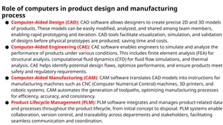
● Computer-Aided Design (CAD): CAD software allows designers to create precise 2D and 3D models
of products. These models can be easily modified, analyzed, and shared among team members,
enabling rapid prototyping and iteration. CAD tools facilitate visualization, simulation, and validation
of designs before physical prototypes are produced, saving time and costs.
● Computer-Aided Engineering (CAE): CAE software enables engineers to simulate and analyze the
performance of products under various conditions. This includes finite element analysis (FEA) for
structural analysis, computational fluid dynamics (CFD) for fluid flow simulations, and thermal
analysis. CAE helps identify potential design flaws, optimize performance, and ensure products meet
safety and regulatory requirements.
● Computer-Aided Manufacturing (CAM): CAM software translates CAD models into instructions for
manufacturing machines such as CNC (Computer Numerical Control) machines, 3D printers, and
robotic systems. CAM automates the generation of toolpaths, optimizing manufacturing processes
for efficiency, accuracy, and consistency.
● Product Lifecycle Management (PLM): PLM software integrates and manages product-related data
and processes throughout the product lifecycle, from initial concept to disposal. PLM systems enable
collaboration, version control, and traceability across departments and stakeholders, facilitating
seamless communication and coordination.
6.
Role of computersin product design and manufacturing process
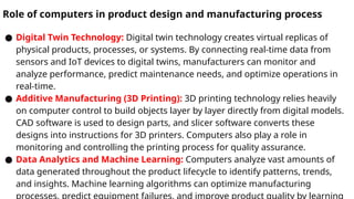
● Digital Twin Technology: Digital twin technology creates virtual replicas of
physical products, processes, or systems. By connecting real-time data from
sensors and IoT devices to digital twins, manufacturers can monitor and
analyze performance, predict maintenance needs, and optimize operations in
real-time.
● Additive Manufacturing (3D Printing): 3D printing technology relies heavily
on computer control to build objects layer by layer directly from digital models.
CAD software is used to design parts, and slicer software converts these
designs into instructions for 3D printers. Computers also play a role in
monitoring and controlling the printing process for quality assurance.
● Data Analytics and Machine Learning: Computers analyze vast amounts of
data generated throughout the product lifecycle to identify patterns, trends,
and insights. Machine learning algorithms can optimize manufacturing
7.
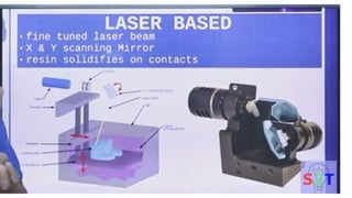
Prototyping techniques suchas Stereolithography (SLA)
● Stereolithography (SLA) is a popular prototyping
technique used in additive manufacturing (AM)
or 3D printing.
● It involves the use of a photosensitive resin that
solidifies when exposed to ultraviolet (UV) light.
Here's how the SLA process works:
10.
Prototyping techniques suchas Stereolithography
(SLA)
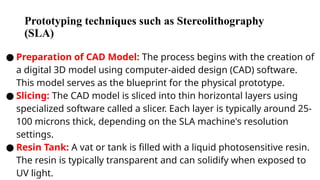
● Preparation of CAD Model: The process begins with the creation of
a digital 3D model using computer-aided design (CAD) software.
This model serves as the blueprint for the physical prototype.
● Slicing: The CAD model is sliced into thin horizontal layers using
specialized software called a slicer. Each layer is typically around 25-
100 microns thick, depending on the SLA machine's resolution
settings.
● Resin Tank: A vat or tank is filled with a liquid photosensitive resin.
The resin is typically transparent and can solidify when exposed to
UV light.
11.
Prototyping techniques suchas Stereolithography
(SLA)
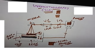
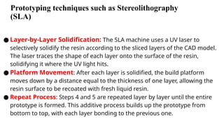
● Layer-by-Layer Solidification: The SLA machine uses a UV laser to
selectively solidify the resin according to the sliced layers of the CAD model.
The laser traces the shape of each layer onto the surface of the resin,
solidifying it where the UV light hits.
● Platform Movement: After each layer is solidified, the build platform
moves down by a distance equal to the thickness of one layer, allowing the
resin surface to be recoated with fresh liquid resin.
● Repeat Process: Steps 4 and 5 are repeated layer by layer until the entire
prototype is formed. This additive process builds up the prototype from
bottom to top, with each layer bonding to the previous one.
12.
Prototyping techniques suchas Stereolithography (SLA)
https://www.youtube.com/watch?v=1U0dTcsaa_8
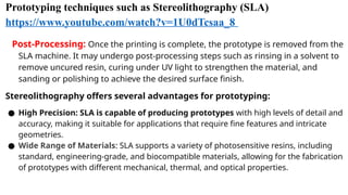
Post-Processing: Once the printing is complete, the prototype is removed from the
SLA machine. It may undergo post-processing steps such as rinsing in a solvent to
remove uncured resin, curing under UV light to strengthen the material, and
sanding or polishing to achieve the desired surface finish.
Stereolithography offers several advantages for prototyping:
● High Precision: SLA is capable of producing prototypes with high levels of detail and
accuracy, making it suitable for applications that require fine features and intricate
geometries.
● Wide Range of Materials: SLA supports a variety of photosensitive resins, including
standard, engineering-grade, and biocompatible materials, allowing for the fabrication
of prototypes with different mechanical, thermal, and optical properties.
13.
Prototyping techniques suchas Stereolithography (SLA)
● Fast Turnaround: SLA can produce prototypes relatively
quickly compared to traditional manufacturing methods,
allowing for rapid iteration and design validation.
● Complex Geometries: SLA can create prototypes with
complex shapes and internal structures that may be
difficult or impossible to produce using traditional
machining techniques.
14.
● Selective lasersintering (SLS)
https://www.youtube.com/watch?v=sRC8W77MlrY
● Selective Laser Sintering (SLS) is another popular
additive manufacturing technique used for
creating prototypes, functional parts, and even end-
use products. Unlike stereolithography (SLA)
which uses liquid resin,
● SLS employs a powdered material, typically polymers
such as nylon, thermoplastic polyurethane (TPU), or
thermoplastic elastomer (TPE), and sometimes
metals like aluminum or steel.
15.
Selective laser sintering(SLS)
Preparation of CAD Model: Similar to other additive manufacturing
processes, the process begins with the creation of a digital 3D model using
computer-aided design (CAD) software. This digital model serves as the
blueprint for the physical object.
Sintering Chamber: In the SLS machine, a thin layer of powdered material
(typically between 30 and 100 microns thick) is spread uniformly across a
build platform inside a controlled environment.
Selective Sintering: A high-powered laser selectively scans and fuses the
powdered material according to the cross-sections of the 3D model. The laser
heats the powdered material to just below its melting point, causing the
particles to fuse together. This process repeats layer by layer, with each new
layer of powder spread over the previous one.
16.
Selective laser sintering(SLS)
● Layer-by-Layer Building: After each layer is sintered, the build platform
descends by one layer thickness, and a recoating blade spreads a fresh
layer of powder over the previously sintered layer. The laser then
selectively sinters the new layer, fusing it to the layer below.
● Cooling and Solidification: Once the entire object is built layer by layer, it
remains within the powder bed to cool down. The unused powder acts as a
support structure during the printing process, eliminating the need for
additional support structures typically required in other 3D printing
techniques.
● Post-Processing: After printing, the excess powder is removed, and the
printed part undergoes additional post-processing steps such as sanding,
polishing, or dyeing to achieve the desired surface finish.
17.
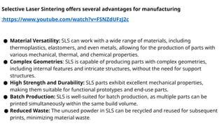
Selective Laser Sinteringoffers several advantages for manufacturing
:https://www.youtube.com/watch?v=FSNZdUFzJ2c
● Material Versatility: SLS can work with a wide range of materials, including
thermoplastics, elastomers, and even metals, allowing for the production of parts with
various mechanical, thermal, and chemical properties.
● Complex Geometries: SLS is capable of producing parts with complex geometries,
including internal features and intricate structures, without the need for support
structures.
● High Strength and Durability: SLS parts exhibit excellent mechanical properties,
making them suitable for functional prototypes and end-use parts.
● Batch Production: SLS is well-suited for batch production, as multiple parts can be
printed simultaneously within the same build volume.
● Reduced Waste: The unused powder in SLS can be recycled and reused for subsequent
prints, minimizing material waste.
18.
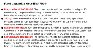
Fused disposition Modelling(FDM)
● Preparation of CAD Model: The process starts with the creation of a digital 3D
model using computer-aided design (CAD) software. This model serves as the
blueprint for the physical object to be printed.
● Slicing: The CAD model is sliced into thin horizontal layers using specialized
software called a slicer. Each layer is typically around 0.1 to 0.3 millimeters thick,
depending on the printer's resolution settings.
● Material Loading: A spool of thermoplastic filament is loaded into the FDM printer.
Common filament materials include acrylonitrile butadiene styrene (ABS), polylactic
acid (PLA), nylon, and thermoplastic polyurethane (TPU), among others.
● Extrusion and Deposition: The FDM printer heats the filament material to its
melting point and extrudes it through a nozzle onto a build platform or previous
layers. The nozzle moves along the X, Y, and Z axes according to the instructions
from the sliced layers, depositing material and building up the object layer by layer.
20.
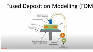
Fused Deposition Modelling(FDM)
Layer Bonding: As the extruded material is deposited, it fuses with the
previous layers upon cooling, creating a strong bond between the layers.
Support Structures (if needed): For overhanging or complex geometries, the
slicer software may generate support structures made of the same material
as the object. These supports hold up the unsupported sections during
printing and are later removed in post-processing.
Cooling and Solidification: After each layer is deposited, it cools and solidifies,
allowing the subsequent layers to adhere to it.
Completion and Post-Processing: Once the printing is complete, the object
may undergo post-processing steps such as removing support structures,
sanding, smoothing, or painting to achieve the desired surface finish.
21.
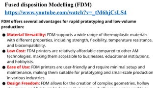
Fused disposition Modelling(FDM)
https://www.youtube.com/watch?v=_tM6hjCsLS4
FDM offers several advantages for rapid prototyping and low-volume
production:
● Material Versatility: FDM supports a wide range of thermoplastic materials
with different properties, including strength, flexibility, temperature resistance,
and biocompatibility.
● Low Cost: FDM printers are relatively affordable compared to other AM
technologies, making them accessible to businesses, educational institutions,
and hobbyists.
● Ease of Use: FDM printers are user-friendly and require minimal setup and
maintenance, making them suitable for prototyping and small-scale production
in various industries.
● Design Freedom: FDM allows for the creation of complex geometries, hollow
23.
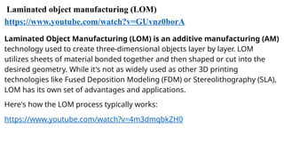
Laminated object manufacturing(LOM)
https://www.youtube.com/watch?v=GUvnz0borA
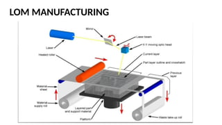
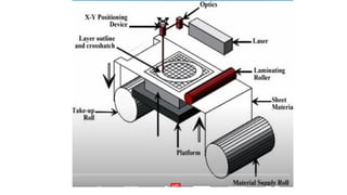
Laminated Object Manufacturing (LOM) is an additive manufacturing (AM)
technology used to create three-dimensional objects layer by layer. LOM
utilizes sheets of material bonded together and then shaped or cut into the
desired geometry. While it's not as widely used as other 3D printing
technologies like Fused Deposition Modeling (FDM) or Stereolithography (SLA),
LOM has its own set of advantages and applications.
Here's how the LOM process typically works:
https://www.youtube.com/watch?v=4m3dmqbkZH0
24.
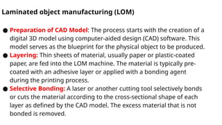
Laminated object manufacturing(LOM)
● Preparation of CAD Model: The process starts with the creation of a
digital 3D model using computer-aided design (CAD) software. This
model serves as the blueprint for the physical object to be produced.
● Layering: Thin sheets of material, usually paper or plastic-coated
paper, are fed into the LOM machine. The material is typically pre-
coated with an adhesive layer or applied with a bonding agent
during the printing process.
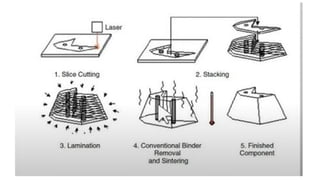
● Selective Bonding: A laser or another cutting tool selectively bonds
or cuts the material according to the cross-sectional shape of each
layer as defined by the CAD model. The excess material that is not
bonded is removed.
Laminated object manufacturing(LOM)
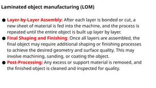
● Layer-by-Layer Assembly: After each layer is bonded or cut, a
new sheet of material is fed into the machine, and the process is
repeated until the entire object is built up layer by layer.
● Final Shaping and Finishing: Once all layers are assembled, the
final object may require additional shaping or finishing processes
to achieve the desired geometry and surface quality. This may
involve machining, sanding, or coating the object.
● Post-Processing: Any excess or support material is removed, and
the finished object is cleaned and inspected for quality.
28.
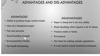
LOM offers severaladvantages for certain applications:
● Material Versatility: LOM can use a variety of materials, including paper,
plastic, and composites, allowing for the production of objects with different
mechanical, thermal, and aesthetic properties.
● Low Cost: LOM is often more cost-effective than other AM technologies,
particularly for larger parts or prototypes, as it typically uses inexpensive raw
materials and requires minimal equipment investment.
● Large Build Volume: LOM machines can produce relatively large objects
compared to some other 3D printing technologies, making them suitable for
printing prototypes, architectural models, and functional parts.
● No Support Structures: Unlike some other 3D printing methods, LOM does not
require support structures, as the excess material acts as support during the
printing process. This can simplify post-processing and reduce material waste.
31.
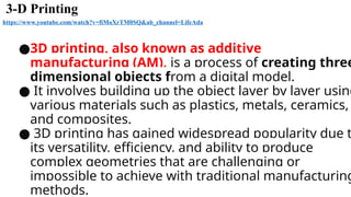
3-D Printing
https://www.youtube.com/watch?v=fiMoXrTM0SQ&ab_channel=LifeAda
●3D printing,also known as additive
manufacturing (AM), is a process of creating three
dimensional objects from a digital model.
● It involves building up the object layer by layer using
various materials such as plastics, metals, ceramics,
and composites.
● 3D printing has gained widespread popularity due t
its versatility, efficiency, and ability to produce
complex geometries that are challenging or
impossible to achieve with traditional manufacturing
methods.
32.
3-D printing
Creation ofDigital Model: The process begins with the creation of a digital
3D model using computer-aided design (CAD) software or by scanning an
existing object using 3D scanning technologies.
Slicing: The digital model is sliced into thin horizontal layers using
specialized software called a slicer. Each layer represents a cross-section of
the object to be printed.
Material Selection: Depending on the 3D printing technology being used,
various materials can be employed, including thermoplastics,
photopolymers, metals, ceramics, and composite materials. The choice of
material depends on factors such as strength, flexibility, temperature
resistance, and surface finish requirements.
33.
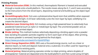
Printing Process:
● MaterialExtrusion (FDM): In this method, thermoplastic filament is heated and extruded
through a nozzle onto a build platform. The nozzle moves along the X, Y, and Z axes according
to the instructions from the sliced layers, depositing material and building up the object layer
by layer.
● Stereolithography (SLA): SLA uses a photosensitive liquid resin that solidifies when exposed
to ultraviolet (UV) light. A UV laser selectively cures the resin layer by layer, solidifying it to
create the desired object.
● Selective Laser Sintering (SLS): SLS involves using a high-powered laser to selectively fuse
powdered material (such as nylon or metal) layer by layer. The unsintered powder acts as
support for the printed object.
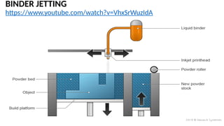
● Binder Jetting: This method involves selectively depositing a binding agent onto a powder
bed, bonding the powder particles together to form each layer of the object. After printing,
the excess powder is removed, leaving behind the final object.
https://www.youtube.com/watch?v=hjIoGPZPNjU
● Direct Energy Deposition (DED): DED uses a focused energy source, such as a laser or
electron beam, to melt and deposit material onto a substrate. It is often used for repairing or
adding material to existing parts.
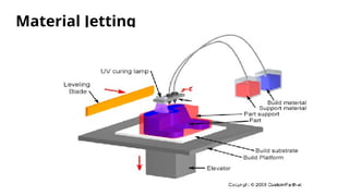
● Material Jetting: Material jetting operates similar to inkjet printing, where droplets of
photopolymer material are deposited onto the build platform and then cured using UV light.
● Post-Processing: Afterprinting, the object may undergo post-processing
steps such as support removal, surface finishing (sanding, polishing,
painting), heat treatment, or additional machining to achieve the desired
final product.
● Quality Control: The printed object is inspected for dimensional
accuracy, surface defects, and other quality attributes to ensure it meets
the specifications of the original design.
● 3D printing finds applications across various industries, including
aerospace, automotive, healthcare, architecture, consumer goods,
and education. It is used for prototyping, customization, low-volume
production, tooling, and rapid manufacturing, among other
purposes. As the technology continues to advance, 3D printing is
expected to play an increasingly significant role in transforming
manufacturing and product development processes.
https://www.youtube.com/watch?v=4coIacNNl28&ab_channel=3DPrintingNerd
40.
Ballistic Particle Manufacturing(BPM)
https://www.youtube.com/watch?v=iwtC4HR3p-g&ab_channel=danielcavero
● Ballistic Particle Manufacturing (BPM) is an additive
manufacturing (AM) process that belongs to the
family of powder bed fusion techniques.
● Developed at the Lawrence Livermore National
Laboratory (LLNL), BPM utilizes metal particles
accelerated by high-energy gas jets to build up a
3D object layer by layer.
41.
Ballistic Particle Manufacturing(BPM)
● Powder Deposition: A layer of metal powder is spread
uniformly onto a build platform using a powder deposition
system.
● Particle Acceleration: High-pressure gas jets or "projectiles"
are precisely directed at the powder bed, accelerating metal
particles to high velocities.
● Impact and Bonding: The accelerated particles collide with the
powder bed surface, causing localized melting and bonding.
This creates a solid layer of material corresponding to the
desired shape of the object's cross-section.
42.
Ballistic Particle Manufacturing(BPM)
● Layer-by-Layer Build-Up: The build platform is then lowered,
and a new layer of powder is spread over the previously
deposited layer. The process repeats, with particles being
accelerated and impacting the powder bed to build up the object
layer by layer.
● Cooling and Solidification: Once each layer is deposited and
fused, it cools and solidifies. This process continues until the
entire object is built.
● Post-Processing: After the printing process is complete, excess
powder is removed, and the object may undergo additional heat
treatment or surface finishing processes to improve mechanical
properties or achieve the desired surface finish.
43.
BPM offers severaladvantages compared to other AM
techniques:
● Speed: BPM is capable of high-speed printing due to the rapid acceleration
of particles, enabling the production of parts with shorter lead times.
● Material Flexibility: It can process a wide range of metals, including
aluminum, titanium, stainless steel, and nickel-based alloys, allowing for the
production of parts with diverse material properties.
● Reduced Support Structures: Since BPM uses a powder bed, it often requires
fewer or no support structures compared to other AM techniques, reducing
material waste and post-processing requirements.
● High Resolution: BPM can achieve fine feature resolution and surface finish,
making it suitable for producing complex geometries and intricate designs.
44.
BPM also hassome limitations
● Equipment Complexity: BPM systems typically require complex and expensive
equipment, including high-pressure gas delivery systems and precise control
mechanisms.
● Material Handling: Handling metal powders can pose safety and environmental
risks, requiring specialized equipment and procedures for powder handling and
disposal.
● Surface Quality: While BPM can achieve high-resolution parts, the surface finish may
require additional post-processing to meet certain application requirements.
Overall, Ballistic Particle Manufacturing is a promising AM technology with the potential
to produce high-quality metal parts quickly and efficiently, particularly for applications
requiring complex geometries and high material performance.
However, further development and refinement of the technology are still ongoing to
address its challenges and improve its capabilities.