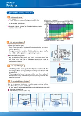
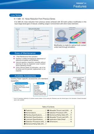
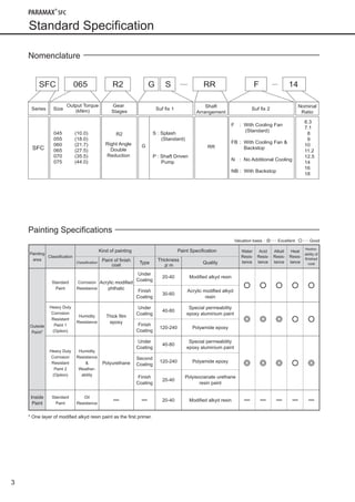
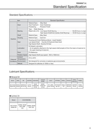
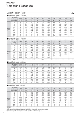
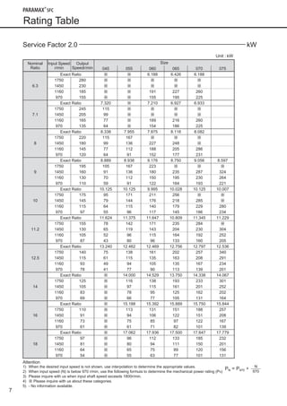
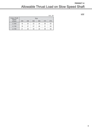
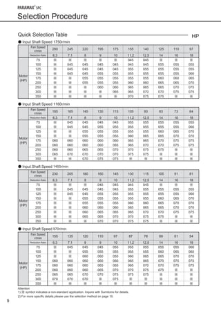
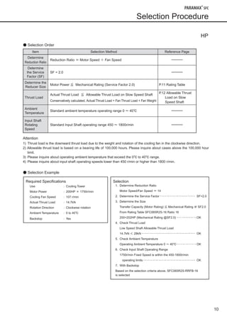
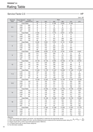
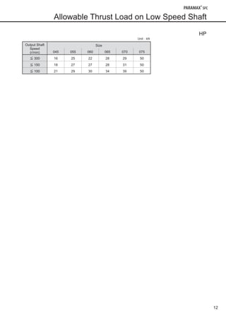
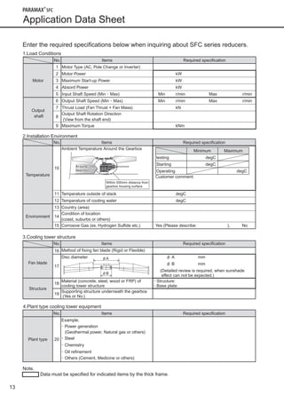
No. G2201E-2No. G2201E-2.1
CW21
PARAMAX SFCSeries
TheCoolingTowerDrives
®
Issued 2009.12
1
Features
Optimised for cooling tower use
1 Selection Criteria
●	 The SFC Series was specifically designed for the 	
	 cooling tower environment.
●	 Use the chart to find the correct size based on motor
size and fan speed.
2 Low Vibration Design
●	 Extended Bearing Span
	 Even if the cooling fan is balanced, excess vibration can occur
during operation.
	 Using an extended fan drive shaft (gearbox low speed shaft),
run-out due to fan operation is significantly reduced.
●	 Balanced Mounting Load
	 By arranging the mounting bolt holes uniformly about the
fan drive shaft, the load to the gearbox mounting base is
transmitted uniformly.
3 Flat Mount Design
The SFC gearbox is designed without protrusions beneath the
mounting surface, leading to simple mounting base design and
construction.
The design also takes into account the use of an optional
backstop and pump to be added without protruding beneath the
mounting surface.
4 Thermally Efficient Design
Due to the gearbox location in a cooling tower, minimal airflow
from the cooling tower fan reaches it.
The SFC gearbox is designed with maximum heat dissipation in mind.
● Maximized Surface Area
● High Efficiency Gearbox Cooling Fan
Motor(kW)
Motor Size vs. Fan Speed Input Speed 1800r/min
Reduction
Ratio
r/min
FanSpeed
Gearbox
Size
112 100225 200 180 160 144 128285 253
16 188 9 10 11.2 12.5 146.3 7.1
SFC045 SFC055 SFC060 SFC065 SFC070 SFC075
55
75
90
110
132
160
200
250
280
∗Refer to the selection table on page 5 for detatils.
Backstop (Optional)
Oil Pump (Optional)
Flat Mount Design
ExtenedBearingSpan
Fan Weight and
Thrust Load
Uniform Mounting Load
Symetric Mounting Holes
Air Flow Around the Gearbox
Cooling Fan
Forced Cooling
Stagnant Air
With a Gearbox Cooling Fan
(SFC Series)
Without a Gearbox Cooling Fan
Flat Mount Design
ExtenedBearingSpan
Backstop (Optional)
Oil Pump (Optional)
090624_SFC Series_E.indd 2 2009/12/15 17:34:57
2
Low Noise
6 ~ 8dB(A)Noise Reduction From Previous Series
6 to 8dB (A) noise reduction from previous series achieved with 3D tooth surface modification in the
input stage bevel gear of reducer, enabling usage in environment with strict noise restriction.
Ease of Maintenance
● 1 Year Maintenance free operation.
● Gearbox is drilled and tapped for attachment of
external air breather and oil fill/drain.
● Internal gearbox inspection possible without
draining oil due to inspection cover location
above operating oil level.
● Using internal splash oil lubrication, use of an
oil pump and its periodic replacement is not
required.
Available Accessories
Cooling Tower specific accessories are standard
equipment.
* Use of a backstop (optional) is to prevent reverse rotation of the cooling fan. Backstop uses the internal gear oil for lubrication. Grease lubrication
type is also available.
Features
Oil Fill
Air Breather
Inspection
Cover
Pipe Threads
Oil Drain
External Oil Gage Pipe
Fan Stack
Cooling Fan
Oil Splasher
(Splash Lubrication)
Oil Seal Hood (Output Shaft)
Magnetic Plug
Oil Gauge
Backstop (optional)
Oil Pump (optional)
Standard Equipment
Integral Cooling Fan
Oil Seal Hood (Output Shaft)
Oil Gauge
Magnetic Plug
Backstop
Oil Heater
Oil Pump
Flow Switch
Oil Level Switch
Dust-free Air Breather
Vibration Sensor Seat
*
Options
Table of Contents
● Features..............................1 ● Allowable Thrust Load (kW).....8
● Nomenclature......................3 ● Selection Procedure (HP)........9
● Painting Specifications........3 ● Mechanical Rating Table (HP) ...11
● Standard Specifications ......4 ● Allowable Thrust Load (HP) ...12
● Lubricant Specifications......4 ● Application Data Sheet ..........13
● Selection Procedure (kW)...5 ● Dimensions............................14
● Mechanical Rating Table (kW)....7
Noise Level of SFC Series
(Noise Level at 1m from Reducer Side)
Condition: Input Speed at 1,500r/min with Cooling Fan
Noise Level
Previous Model
Low Noise Model
Motor Power
Modification is made for optimal tooth contact
under load through simulation.
090624_SFC Series_E.indd 3 2009/12/15 17:35:00
3
Standard Specification
Nomenclature
Painting Specifications
Valuation basis:◎・・・ Excellent,○・・・ Good
Painting
area
Classification
Kind of painting Paint Specification Water
Resis-
tance
Acid
Resis-
tance
Alkali
Resis-
tance
Heat
Resis-
tance
Weather-
ability of
finished
coatClassification
Paint of finish
coat
Type
Thickness
μm
Quality
Outside
Paint*
Standard
Paint
Corrosion
Resistance
Acrylic modified
phthalic
Under
Coating
20-40 Modified alkyd resin
○ ○ ○ ○ ○
Finish
Coating
30-60
Acrylic modified alkyd
resin
Heavy Duty
Corrosion
Resistant
Paint 1
(Option)
Humidity
Resistance
Thick film
epoxy
Under
Coating
40-80
Special permeability
epoxy aluminium paint
◎ ◎ ◎ ○ ○
Finish
Coating
120-240 Polyamide epoxy
Heavy Duty
Corrosion
Resistant
Paint 2
(Option)
Humidity
Resistance
&
Weather-
ability
Polyurethane
Under
Coating
40-80
Special permeability
epoxy aluminium paint
◎ ◎ ◎ ○ ◎
Second
Coating
120-240 Polyamide epoxy
Finish
Coating
20-40
Polyisocianate urethane
resin paint
Inside
Paint
Standard
Paint
Oil
Resistance
ー ー 20-40 Modified alkyd resin ー ー ー ー ー
* One layer of modified alkyd resin paint as the first primer.
SFC
Series
Gear
Stages
Suf fix 1
Shaft
Arrangement
Suf fix 2
Nominal
Ratio
Size
Output Torque
(kNm)
R2 S : Splash
(Standard)
P : Shaft Driven
Pump
RRG
6.3
7.1
8
9
10
11.2
12.5
14
16
18
045 (10.0)
055 (18.0)
060 (21.7)
065 (27.5)
070 (35.5)
075 (44.0)
SFC 065 R2 14RRSG F
Right Angle
Double
Reduction
F : With Cooling Fan
(Standard)
FB : With Cooling Fan &
Backstop
N : No Additional Cooling
NB : With Backstop
090624_SFC Series_E.indd 4 2009/12/15 17:35:01
4
Standard Specification
Standard Specifications
Item Standard Specification
Gearbox
Gear
Material Spec. : Alloy Steel
Heat Treatment : Case Hardening
Processing : Precision Finish
Bearing
Type : Roller Bearing
Rated Life (L10) : Low Speed Shaft Bearing ・・・・・・・・・・・・・・・・・・・・・ 100,000 Hours or Longer
High Speed Shaft/Intermediate Shaft Bearings ・・・ 50,000 Hours or Longer
Shaft Material Spec. : Alloy Steel
Housing Material Spec. : Cast Iron
Seal
Housing and Cover Mating surfaces : Liquid Sealant
Low Speed Shaft : Dust-lip Oil Seal and Seal Hood
High Speed Shaft : Dust-lip Oil Seal
Lubrication
Oil Splash Lubrication
An oil splasher attached to the high speed shaft propels oil from the lower oil reservoir to
the upper bearing oil reservoir.
Paint P3 Reference
Rotation Speed High Speed Shaft input speed: 450 to 1800r/min
External
Conditions
Ambient
Temperature
0℃ to 40℃
Environment Not designed for corrosive or explosive gas environments.
Altitude Designed for altitudes of 1000m or less.
Lubricant Specifications
● Mineral Oil
Brand ARAL BP CASTROL CHEVRON
EXXON
MOBIL
GULF OPTIMOL SHELL TEXACO
TOTAL
FINA ELF
THIBOL
ISO VG320
AGMA 6EP
DEGOL
BG320
ENERGOL
GR-XP-320
ALPHA
SP320
GEAR
COMPOUNS
EP320
MOBIL-
GEAR 600
XP320
EP LUBRI-
CANT HD320
OPTIGEAR
BM 320
OMALA
320
MEROPA
WM 320
CARTER
EP320
THIBOL
1100/320
● Synthetic Oil
Brand EXXONMOBIL
ISO VG320
AGMA 6S
MOBIL GEAR
SHC XMP
320
MOBIL GEAR
SHC 320
090624_SFC Series_E.indd 5 2009/12/15 17:35:01
5
Selection Procedure
Quick Selection Table
● Input Shaft Speed 1750r/min
Fan Speed
r/min
280 245 220 195 175 155 140 125 110 97
Reduction Ratio 6.3 7.1 8 9 10 11.2 12.5 14 16 18
Motor
(kW)
55 ※ ※ ※ ※ ※ 045 045 ※ ※ ※
75 ※ 045 045 045 045 045 045 055 055 055
90 ※ 045 045 045 045 055 055 055 055 055
110 ※ 045 045 055 055 055 055 055 055 060
132 ※ ※ 055 055 055 055 055 060 065 065
160 ※ ※ 055 055 055 060 060 065 070 070
200 ※ ※ ※ 060 060 065 065 070 075 075
250 ※ ※ ※ ※ 065 070 070 075 075 ―
280 ※ ※ ※ ※ ※ 070 075 075 ― ―
● Input Shaft Speed 1160r/min
Fan Speed
r/min
185 165 145 130 115 105 93 83 73 64
Reduction Ratio 6.3 7.1 8 9 10 11.2 12.5 14 16 18
Motor
(kW)
55 ※ 045 045 045 045 055 055 055 055 055
75 ※ 045 045 055 055 055 055 055 055 060
90 ※ ※ 055 055 055 055 060 060 065 070
110 ※ ※ 055 055 055 060 065 065 070 070
132 060 060 060 060 060 065 065 070 075 075
160 060 060 060 065 065 065 070 070 075
200 065 065 065 065 070 075 075 075
250 065 070 070 075 075 075
280 075
● Input Shaft Speed 1450r/min
Fan Speed
r/min
230 205 180 160 145 130 115 105 91 81
Reduction Ratio 6.3 7.1 8 9 10 11.2 12.5 14 16 18
Motor
(kW)
55 ※ ※ ※ 045 045 045 045 ※ ※ ※
75 ※ 045 045 045 045 055 055 055 055 055
90 ※ 045 045 045 055 055 055 055 055 060
110 ※ ※ 055 055 055 055 055 060 065 065
132 ※ ※ 055 055 055 060 060 065 070 070
160 ※ ※ 060 060 060 065 065 065 075 075
200 ※ ※ 060 065 065 065 070 070 075 075
250 ※ ※ 065 065 070 075 075 075 ※ ※
280 ※ ※ ※ 070 070 075 075 ※ ※ ※
● Input Shaft Speed 970r/min
Fan Speed
r/min
155 135 120 110 97 87 78 69 61 54
Reduction Ratio 6.3 7.1 8 9 10 11.2 12.5 14 16 18
Motor
(kW)
55 ※ 045 045 045 045 055 055 055 055 055
75 ※ ※ 055 055 055 055 055 060 065 065
90 ※ ※ 055 055 055 060 060 065 070 070
110 060 060 060 060 060 065 065 070 075 075
132 060 060 060 065 065 065 070 075 075 ※
160 065 065 065 065 070 070 075 075 ※ ※
200 065 065 070 075 075 075 075 ※ ※ ※
250 ※ ※ ※ ※ ※ ※ ※ ※ ※ ※
280 ※ ※ ※ ※ ※ ※ ※ ※ ※ ※
Attention
1) ※ symbol indicates a non-standard application. Inquire with Sumitomo for details.
2) For more specific details please use the selection method on page 6.
kW
090624_SFC Series_E.indd 6 2009/12/15 17:35:02
6
kW
● Selection Order
Item Selection Method Reference Page
Determine
Reduction Ratio
Reduction Ratio = Motor Speed ÷ Fan Speed ーーーー
Determine
the Service
Factor (SF)
SF = 2.0 ーーーー
Determine the
Reducer Size
Motor Power ≦ Mechanical Rating (Service Factor 2.0) P.7 Rating Table
Thrust Load
Actual Thrust Load ≦ Allowable Thrust Load on Slow Speed Shaft
Conservatively calculated, Actual Thrust Load = Fan Thrust Load + Fan Weight
P.8 Allowable Thrust
Load on Slow
Speed Shaft
Ambient
Temperature
Standard ambient temperature operating range 0 ~ 40℃ ーーーー
Input Shaft
Rotating
Speed
Standard Input Shaft operating range 450 ~ 1800r/min ーーーー
Attention
1) Thrust load is the downward thrust load due to the weight and rotation of the cooling fan in the clockwise direction.
2) Allowable thrust load is based on a bearing life of 100,000 hours. Please inquire about cases above the 100,000 hour
limit.
3) Please inquire about operating ambient temperature that exceed the 0℃ to 40℃ range.
4) Please inquire about input shaft operating speeds lower than 450 r/min or higher than 1800 r/min.
● Selection Example
Selection Procedure
Required Specifications
Use :Cooling Tower
Motor Power :132kW × 1500r/min
Cooling Fan Speed :107 r/min
Actual Thrust Load :14.7kN
Rotation Direction :Clockwise rotation
Ambient Temperature :0 to 40℃
Backstop :Yes
Selection
1. Determine Reduction Ratio
Motor Speed/Fan Speed = 14
2. Determine the Service Factor ・・・・・・・・・・・・・・・・・・・・・・・ SF=2.0
3. Determine the Size
Transfer Capacity (Motor Rating) ≦ Mechanical Rating @ SF2.0
From Rating Table SFC065R2S-14 Ratio 14
132<160kW (Mechanical Rating @SF2.0) ・・・・・・・・・・・・ OK
4. Check Thrust Load
Low Speed Shaft Allowable Thrust Load
14.7kN < 28kN ・・・・・・・・・・・・・・・・・・・・・・・・・・・・・・・・・・・ OK
5. Check Ambient Temperature
Operating Ambient Temperature 0 ~ 40℃・・・・・・・・・・・・・ OK
6. Check Input Shaft Operating Range
1500r/min Fixed Speed is within the 450-1800r/min
operating limits ・・・・・・・・・・・・・・・・・・・・・・・・・・・・・・・・・・ OK
7. With Backstop
Based on the selection criteria above, SFC065R2S-RRFB-14
is selected
090624_SFC Series_E.indd 7 2009/12/15 17:35:03
7
Rating Table
Service Factor 2.0 kW
Unit : kW
Nominal
Ratio
Input Speed
r/min
Output
Speedr/min
Size
045 055 060 065 070 075
6.3
Exact Ratio ※ ※ 6.188 6.426 6.188
1750 280 ※ ※ ※ ※ ※
1450 230 ※ ※ ※ ※ ※
1160 185 ※ ※ 191 227 260
970 155 ※ ※ 155 195 225
7.1
Exact Ratio 7.320 ※ 7.210 6.927 6.933
1750 245 115 ※ ※ ※ ※
1450 205 99 ※ ※ ※ ※
1160 165 77 ※ 189 216 260
970 135 64 ※ 154 186 225
8
Exact Ratio 8.338 7.955 7.875 8.118 8.082
1750 220 115 167 ※ ※ ※
1450 180 99 136 227 248 ※
1160 145 77 112 188 205 286
970 120 64 91 152 177 231
9
Exact Ratio 8.889 8.938 9.176 8.750 9.056 8.597
1750 195 105 167 223 ※ ※ ※
1450 160 91 136 180 235 287 324
1160 130 70 112 150 195 230 264
970 110 59 91 122 164 193 221
10
Exact Ratio 10.125 10.125 9.995 10.028 10.125 10.007
1750 175 95 171 211 256 ※ ※
1450 145 79 144 176 218 285 ※
1160 115 64 115 140 179 229 280
970 97 55 96 117 145 186 234
11.2
Exact Ratio 11.624 11.375 11.647 10.809 11.345 11.229
1750 155 78 142 171 235 284 ※
1450 130 65 119 143 204 230 304
1160 105 52 96 115 164 192 252
970 87 43 80 96 133 160 205
12.5
Exact Ratio 13.240 12.462 12.469 12.756 12.797 12.536
1750 140 75 138 161 202 257 340
1450 115 61 115 135 163 208 291
1160 93 49 94 105 135 167 234
970 78 41 77 90 113 139 201
14
Exact Ratio ※ 14.000 14.529 13.750 14.338 14.067
1750 125 ※ 116 138 193 233 301
1450 105 ※ 97 115 161 201 252
1160 83 ※ 78 95 125 162 202
970 69 ※ 66 77 105 131 164
16
Exact Ratio ※ 15.188 15.392 15.889 15.750 15.844
1750 110 ※ 113 131 151 188 257
1450 91 ※ 94 106 122 151 208
1160 73 ※ 75 85 97 122 167
970 61 ※ 61 71 82 101 139
18
Exact Ratio ※ 17.062 17.936 17.500 17.647 17.779
1750 97 ※ 96 112 133 185 232
1450 81 ※ 80 94 111 150 201
1160 64 ※ 65 75 89 120 156
970 54 ※ 55 63 77 101 131
Attention
1) When the desired input speed is not shown, use interpolation to determine the appropriate values.
2) When input speed (N) is below 970 r/min, use the following formula to determine the mechanical power rating (PN)
3) Please inquire with us when input shaft speed exceeds 1800r/min.
4) ※ Please inquire with us about these categories.
5) - No information available.
PN = P970 × N
970
090624_SFC Series_E.indd 8 2009/12/15 17:35:04
8
kWUnit:kN
Output Shaft
Speed
(r/min)
Size
045 055 060 065 070 075
≦ 300 16 25 22 28 29 50
≦ 150 18 27 27 28 31 50
≦ 100 21 29 30 34 39 50
Allowable Thrust Load on Slow Speed Shaft
090624_SFC Series_E.indd 9 2009/12/15 17:35:04
9
Selection Procedure
Quick Selection Table
● Input Shaft Speed 1750r/min
Fan Speed
r/min
280 245 220 195 175 155 140 125 110 97
Reduction Ratio 6.3 7.1 8 9 10 11.2 12.5 14 16 18
Motor
(HP)
75 ※ ※ ※ ※ ※ 045 045 ※ ※ ※
100 ※ 045 045 045 045 045 045 055 055 055
125 ※ 045 045 045 045 055 055 055 055 055
150 ※ 045 045 055 055 055 055 055 055 060
175 ※ ※ 055 055 055 055 055 060 060 065
200 ※ ※ 055 055 055 060 060 065 065 070
250 ※ ※ ※ 060 060 065 065 065 070 075
300 ※ ※ ※ ※ 065 065 070 070 075 075
350 ※ ※ ※ ※ ※ 070 075 075 ※ ※
● Input Shaft Speed 1160r/min
Fan Speed
r/min
185 165 145 130 115 105 93 83 73 64
Reduction Ratio 6.3 7.1 8 9 10 11.2 12.5 14 16 18
Motor
(HP)
75 ※ 045 045 045 045 055 055 055 055 055
100 ※ 045 045 055 055 055 055 055 055 060
125 ※ ※ 055 055 055 055 055 060 065 070
150 ※ ※ 055 055 055 060 065 065 070 070
175 060 060 060 060 060 065 065 070 075 075
200 060 060 060 060 065 065 070 070 075 075
250 060 060 065 065 070 070 075 075 ※ ※
300 065 070 070 070 070 075 075 ※ ※ ※
350 ※ ※ 070 075 075 ※ ※ ※ ※ ※
● Input Shaft Speed 1450r/min
Fan Speed
r/min
230 205 180 160 145 130 115 105 91 81
Reduction Ratio 6.3 7.1 8 9 10 11.2 12.5 14 16 18
Motor
(HP)
75 ※ ※ ※ 045 045 045 045 ※ ※ ※
100 ※ 045 045 045 045 055 055 055 055 055
125 ※ 045 045 055 055 055 055 055 055 060
150 ※ ※ 055 055 055 055 055 060 065 070
175 ※ ※ 055 055 055 060 060 065 070 070
200 ※ ※ 060 060 060 065 065 065 070 070
250 ※ ※ 060 065 065 065 070 070 075 075
300 ※ ※ 065 065 070 070 075 075 ※ ※
350 ※ ※ ※ 070 070 075 075 ※ ※ ※
● Input Shaft Speed 970r/min
Fan Speed
r/min
155 135 120 110 97 87 78 69 61 54
Reduction Ratio 6.3 7.1 8 9 10 11.2 12.5 14 16 18
Motor
(HP)
75 ※ 045 045 045 055 055 055 055 055 060
100 ※ ※ 055 055 055 055 055 060 065 065
125 ※ ※ 060 060 055 060 065 065 070 070
150 060 060 060 060 060 065 065 070 075 075
175 060 060 060 065 065 065 070 070 075 075
200 060 060 060 065 070 070 075 075 ※ ※
250 065 065 070 070 075 075 075 ※ ※ ※
300 070 070 070 ※ 075 ※ ※ ※ ※ ※
350 ※ ※ ※ ※ ※ ※ ※ ※ ※ ※
Attention
1) ※ symbol indicates a non-standard application. Inquire with Sumitomo for details.
2) For more specific details please use the selection method on page 10.
HP
090624_SFC Series_E.indd 10 2009/12/15 17:35:05
10
HP
● Selection Order
Item Selection Method Reference Page
Determine
Reduction Ratio
Reduction Ratio = Motor Speed ÷ Fan Speed ーーーー
Determine
the Service
Factor (SF)
SF = 2.0 ーーーー
Determine the
Reducer Size
Motor Power ≦ Mechanical Rating (Service Factor 2.0) P.11 Rating Table
Thrust Load
Actual Thrust Load ≦ Allowable Thrust Load on Slow Speed Shaft
Conservatively calculated, Actual Thrust Load = Fan Thrust Load + Fan Weight
P.12 Allowable Thrust
Load on Slow
Speed Shaft
Ambient
Temperature
Standard ambient temperature operating range 0 ~ 40℃ ーーーー
Input Shaft
Rotating
Speed
Standard Input Shaft operating range 450 ~ 1800r/min ーーーー
Attention
1) Thrust load is the downward thrust load due to the weight and rotation of the cooling fan in the clockwise direction.
2) Allowable thrust load is based on a bearing life of 100,000 hours. Please inquire about cases above the 100,000 hour
limit.
3) Please inquire about operating ambient temperature that exceed the 0℃ to 40℃ range.
4) Please inquire about input shaft operating speeds lower than 450 r/min or higher than 1800 r/min.
● Selection Example
Selection Procedure
Required Specifications
Use :Cooling Tower
Motor Power :200HP × 1750r/min
Cooling Fan Speed :107 r/min
Actual Thrust Load :14.7kN
Rotation Direction :Clockwise rotation
Ambient Temperature :0 to 40℃
Backstop :Yes
Selection
1. Determine Reduction Ratio
Motor Speed/Fan Speed = 14
2. Determine the Service Factor ・・・・・・・・・・・・・・・・・・・・・・・ SF=2.0
3. Determine the Size
Transfer Capacity (Motor Rating) ≦ Mechanical Rating @ SF2.0
From Rating Table SFC065R2S-16 Ratio 16
200<202HP (Mechanical Rating @SF2.0) ・・・・・・・・・・・・・OK
4. Check Thrust Load
Low Speed Shaft Allowable Thrust Load
14.7kN < 28kN ・・・・・・・・・・・・・・・・・・・・・・・・・・・・・・・・・・・ OK
5. Check Ambient Temperature
Operating Ambient Temperature 0 ~ 40℃・・・・・・・・・・・・・ OK
6. Check Input Shaft Operating Range
1750r/min Fixed Speed is within the 450-1800r/min
operating limits ・・・・・・・・・・・・・・・・・・・・・・・・・・・・・・・・・・ OK
7. With Backstop
Based on the selection criteria above, SFC065R2S-RRFB-16
is selected
090624_SFC Series_E.indd 11 2009/12/15 17:35:06
11
Rating Table
Service Factor 2.0 HP
Unit : HP
Nominal
Ratio
Input Speed
r/min
Output
Speedr/min
Size
045 055 060 065 070 075
6.3
Exact Ratio ※ ※ 6.188 6.426 6.188
1750 280 ※ ※ ※ ※ ※
1450 230 ※ ※ ※ ※ ※
1160 185 ※ ※ 256 304 349
970 155 ※ ※ 208 261 302
7.1
Exact Ratio 7.320 ※ 7.210 6.927 6.933
1750 245 154 ※ ※ ※ ※
1450 205 133 ※ ※ ※ ※
1160 165 103 ※ 253 289 349
970 135 86 ※ 207 249 302
8
Exact Ratio 8.338 7.955 7.875 8.118 8.082
1750 220 154 224 ※ ※ ※
1450 180 133 182 304 332 ※
1160 145 103 150 252 274 354
970 120 86 122 204 237 310
9
Exact Ratio 8.889 8.938 9.176 8.750 9.056 8.597
1750 195 141 224 299 ※ ※ ※
1450 160 122 182 241 315 385 434
1160 130 94 150 201 261 308 354
970 110 79 122 164 220 259 296
10
Exact Ratio 10.125 10.125 9.995 10.028 10.125 10.007
1750 175 127 229 283 343 ※ ※
1450 145 106 193 236 292 382 ※
1160 115 86 154 188 240 307 375
970 97 74 129 157 194 249 314
11.2
Exact Ratio 11.624 11.375 11.647 10.809 11.345 11.229
1750 155 105 190 229 315 381 ※
1450 130 87 160 192 274 308 408
1160 105 70 129 154 220 257 338
970 87 58 107 129 178 215 275
12.5
Exact Ratio 13.240 12.462 12.469 12.756 12.797 12.536
1750 140 101 185 216 271 345 456
1450 115 82 154 181 219 279 390
1160 93 66 126 141 181 224 314
970 78 55 103 121 152 186 270
14
Exact Ratio ※ 14.000 14.529 13.750 14.338 14.067
1750 125 ※ 156 185 259 312 404
1450 105 ※ 130 154 216 270 338
1160 83 ※ 105 127 168 217 271
970 69 ※ 89 103 141 176 220
16
Exact Ratio ※ 15.188 15.392 15.889 15.750 15.844
1750 110 ※ 152 176 202 252 345
1450 91 ※ 126 142 164 202 279
1160 73 ※ 101 114 130 164 224
970 61 ※ 82 95 110 135 186
18
Exact Ratio ※ 17.062 17.936 17.500 17.647 17.779
1750 97 ※ 129 150 178 248 311
1450 81 ※ 107 126 149 201 270
1160 64 ※ 87 101 119 161 209
970 54 ※ 74 84 103 135 176
Attention
1) When the desired input speed is not shown, use interpolation to determine the appropriate values.
2) When input speed (N) is below 970 r/min, use the following formula to determine the mechanical power rating (PN)
3) Please inquire with us when input shaft speed exceeds 1800r/min.
4) ※ Please inquire with us about these categories.
5) No information available.
PN = P970 × N
970
090624_SFC Series_E.indd 12 2009/12/15 17:35:07
12
Allowable Thrust Load on Low Speed Shaft
HP
Unit:kN
Output Shaft
Speed
(r/min)
Size
045 055 060 065 070 075
≦ 300 16 25 22 28 29 50
≦ 150 18 27 27 28 31 50
≦ 100 21 29 30 34 39 50
090624_SFC Series_E.indd 13 2009/12/15 17:35:08
13
Application Data Sheet 
Note,
	 Data must be specified for indicated items by the thick frame.
Enter the required specifications below when inquiring about SFC series reducers.
1.Load Conditions
No. Items Required specification
Motor
1 Motor Type (AC, Pole Change or Inverter)
2 Motor Power kW
3 Maximum Start-up Power kW
4 Absord Power kW
5 Input Shaft Speed (Min ・ Max) Min r/min Max r/min
Output
shaft
6 Output Shaft Speed (Min ・ Max) Min r/min Max r/min
7 Thrust Load (Fan Thrust + Fan Mass) kN
8
Output Shaft Rotation Direction
(View from the shaft end)
9 Maximum Torque kNm
4.Plant type cooling tower equipment
No. Items Required specification
Plant type 20
Example.
・ Power generation
(Geothermal power, Natural gas or others)
・ Steel
・ Chemistry
・ Oil refinement
・ Others (Cement, Medicine or others)
2.Installation Environment
No. Items Required specification
Temperature
10
Ambient Temperature Around the Gearbox
Customer comment:
11 Temperature outside of stack degC
12 Temperature of cooling water degC
Environment
13 Country (area)
14
Condition of location
(coast, suburbs or others)
15 Corrosive Gas (ex. Hydrogen Sulfide etc.) Yes (Please describe: ), No
Around the
Gearbox
Within 500mm distance from
gearbox housing surface
Minimum Maximum
testing degC
Starting degC
Operating degC
3.Cooling tower structure
φA
φB
No. Items Required specification
Fan blade
16 Method of fixing fan blade (Rigid or Flexible)
17
Disc diameter φ A mm
φ B mm
(Detailed review is required, when sunshade
effect can not be expected.)
Structure
18
Material (concrete, steel, wood or FRP) of
cooling tower structure
・ Structure:
・ Base plate:
19
Supporting structure underneath the gearbox
(Yes or No.)
090624_SFC Series_E.indd 14 2009/12/15 17:35:09
14
Dimensions 
Low Speed Shaft
W1
V1
X1
Z1
Y1
W2
High Speed Shaft
X2
Z2Z
Y2
S
4- J
(DP2)Oil Drain/Fill
(DP1)Oil Fill
Magnetic Plug
(DP1)Air Vent
Oil Gauge Cooling Fan
B A
L2
P
L1
U
L
K2
H
N2
K1
OL5
N1
M
GG
E1
M M
E1
D D G
DD
FCCK1
	 Unit: mm
Size A B C D E1 G H
J
(Installation Bolt)
L P M
Weight
(kg)
Oil Q'ty
(Liters)
OL
045 725 260 645 200 470 35 38 28 (M24) 725 290 95 365 24 260
055 794 290 714 225 530 40 40 35 (M30) 795 320 105 435 34 290
060 865 305 750 240 560 40 45 35 (M30) 900 370 105 660 55 335
065 946 325 831 260 600 40 45 35 (M30) 990 395 105 830 75 360
070 965 350 850 275 650 50 52 42 (M36) 1010 415 135 960 90 375
075 1018 370 903 295 690 50 52 42 (M36) 1045 450 135 1250 110 410
Size
Low Speed Shaft High Speed Shaft Pipe Thread
V1 U1 L1 X1 Y1 Z1 W1/Depth S FC L2 X2 Y2 Z2 W2/Depth DP1 K1 K2 DP2 N1 N2
045 100m6 210 190 28 10 16 M24/50 45k6 80 80 14 5.5 9 M16/36 R1 190 393 R1 1/4 235 80
055 110m6 210 190 28 10 16 M24/50 50k6 80 80 14 5.5 9 M16/36 R1 210 445 R1 1/4 265 100
060 120m6 210 185 32 11 18 M24/50 60m6 115 105 18 7 11 M20/42 R1 1/4 260 505 R1 1/4 280 105
065 130m6 250 225 32 11 18 M24/50 65m6 115 105 18 7 11 M20/42 R1 1/4 280 555 R1 1/4 300 105
070 140m6 250 225 36 12 20 M30/60 65m6 115 105 18 7 11 M20/42 R1 1/4 290 575 R1 1/4 325 105
075 150m6 250 225 36 12 20 M30/60 65m6 115 105 18 7 11 M20/42 R1 1/4 310 610 R1 1/4 345 105
Attention
(1) Keys and keyways for both high speed and low speed shafts conform to ISO/R773-1969 close key. (JIS B 1301-1996 Parallel Key in
Fastening Type)
(2) The oil quantity shown is approximate. Fill to the appropriate level using the oil level gauge.
(3) Air breather and air breather pipe are assembled by the customer and installed on site. A pipe extending from the gearbox to outside
the fan stack should be prepared. Piping parts are not included.
(4) The installation bolts should be rated JIS Class 8.8 .
(5) To maintain coupling alignment, stop plates or knock pins should be installed to prevent gearbox twisting on its base due to fan opera-
tion.
090624_SFC Series_E.indd 15 2009/12/15 17:35:11
Warranty
Period
The warranty period for the Product shall be 18 months after the shipment of the Product from the
Seller's works or 12 months after the Product comes into operation, whichever comes first.
Warranty
Condition
In the event that any problem or damage to the Product arises during the "Warranty Period" from
defects in the Product whenever the Product is properly installed and combined with the Buyer's
equipment or machines, maintained as specified in the maintenance manual, and properly operated
under the conditions described in the catalog or as otherwise agree upon in writing between the
Seller and the Buyer or its customers; the Seller will provide, at its sole discretion, appropriate repair
or replacement of the Product without charge, except as stipulated in the "Exception for Warranty" as
described below.
However, if the Product is installed or integrated into the Buyer's equipment or machines, the Seller
shall not reimburse the cost of: removal or re-installation of the Product or other incidental costs related
thereto, any lost opportunity, any profit loss or other incidental or consequential losses or damages
incurred by the Buyer or its customers.
Exception
for
Warranty
Not withstanding the above warranty, the warranty as set forth herein shall not apply to any problem or
damage to the Product that is caused by:
1.	 installation, connection, combination or integration of the Product in or to the other equipment or
machine that is rendered by any person or entity other than the Seller;
2.	 insufficient maintenance or improper operation by the Buyer or its customers, such that the Product
is not maintained in accordance with the maintenance manual provided or designated by the Seller;
3.	 improper use or operation of the Product by the Buyer or its customers that is not informed to the
Seller, including, without limitation, the Buyer's or its customers' operation of the Product not in
conformity with the specifications, or use of lubrication oil in the Product that is not recommended
by the Seller;
4.	 any problem or damage on any equipment or machine to which the Product is installed, connected
or combined or on any specifications particular to the Buyer or its customers;
5.	 any changes, modifications, improvements or alterations to the Product or those functions that are
rendered on the Product by any person or entity other than the Seller;
6.	 any parts in the Product that are supplied or designated by the Buyer or its customers;
7.	 earthquake, fire, flood, sea-breeze, gas, thunder, acts of God or any other reasons beyond the
control of the Seller;
8.	 waste, exhaustion, normal wear and tear, or deterioration of the Product's parts, such as bearings,
oil-seals;
9.	 any other troubles, problems or damages to the Product that are not attributable to the Seller.
Warranty
SAFETY PRECAUTIONS
●	 Strictly observe the safety rules for the installation place and the equipment to use.
	 (Industrial Safety and Health Law, Technical Standard for Electric Facilities, Extension Rules, Plant Explosion
Guidelines, Building Standards Law, etc.)
●	 Carefully read the maintenance manual before use. If the maintenance manual is not on hand, make a request
for one to the distributor at which you purchased the product or to our sales department. The maintenance
manual should be sent to the actual user.
●	 Select an appropriate product that matches the operating environment and usage.
●	 Install a protective equipment on the machine side when the machine is used for transportation of passengers or
for elevators, escalators, and dumbwaiters.
●	 When the machine is used for food processing equipment and others that are susceptible to oil, install an oil pan
or other damage preventive devices in case of oil leakage due to failure or termination of service life.
15
The scope of our warranty for our products is limited to the range of our manufacture.
Warranty(Period and contents)
090624_SFC Series_E.indd 16 2009/12/15 17:35:11
090624_SFC Series_E.indd 17 2009/12/15 17:35:11
090624_SFC Series_E.indd 18 2009/12/15 17:35:11

Индустриальные редукторы серии Paramax SFC Cooling Tower Drives Sumitomo

  • 1.
    No. G2201E-2No. G2201E-2.1 CW21 PARAMAXSFCSeries TheCoolingTowerDrives ® Issued 2009.12
  • 2.
    1 Features Optimised for coolingtower use 1 Selection Criteria ● The SFC Series was specifically designed for the cooling tower environment. ● Use the chart to find the correct size based on motor size and fan speed. 2 Low Vibration Design ● Extended Bearing Span Even if the cooling fan is balanced, excess vibration can occur during operation. Using an extended fan drive shaft (gearbox low speed shaft), run-out due to fan operation is significantly reduced. ● Balanced Mounting Load By arranging the mounting bolt holes uniformly about the fan drive shaft, the load to the gearbox mounting base is transmitted uniformly. 3 Flat Mount Design The SFC gearbox is designed without protrusions beneath the mounting surface, leading to simple mounting base design and construction. The design also takes into account the use of an optional backstop and pump to be added without protruding beneath the mounting surface. 4 Thermally Efficient Design Due to the gearbox location in a cooling tower, minimal airflow from the cooling tower fan reaches it. The SFC gearbox is designed with maximum heat dissipation in mind. ● Maximized Surface Area ● High Efficiency Gearbox Cooling Fan Motor(kW) Motor Size vs. Fan Speed Input Speed 1800r/min Reduction Ratio r/min FanSpeed Gearbox Size 112 100225 200 180 160 144 128285 253 16 188 9 10 11.2 12.5 146.3 7.1 SFC045 SFC055 SFC060 SFC065 SFC070 SFC075 55 75 90 110 132 160 200 250 280 ∗Refer to the selection table on page 5 for detatils. Backstop (Optional) Oil Pump (Optional) Flat Mount Design ExtenedBearingSpan Fan Weight and Thrust Load Uniform Mounting Load Symetric Mounting Holes Air Flow Around the Gearbox Cooling Fan Forced Cooling Stagnant Air With a Gearbox Cooling Fan (SFC Series) Without a Gearbox Cooling Fan Flat Mount Design ExtenedBearingSpan Backstop (Optional) Oil Pump (Optional) 090624_SFC Series_E.indd 2 2009/12/15 17:34:57
  • 3.
    2 Low Noise 6 ~8dB(A)Noise Reduction From Previous Series 6 to 8dB (A) noise reduction from previous series achieved with 3D tooth surface modification in the input stage bevel gear of reducer, enabling usage in environment with strict noise restriction. Ease of Maintenance ● 1 Year Maintenance free operation. ● Gearbox is drilled and tapped for attachment of external air breather and oil fill/drain. ● Internal gearbox inspection possible without draining oil due to inspection cover location above operating oil level. ● Using internal splash oil lubrication, use of an oil pump and its periodic replacement is not required. Available Accessories Cooling Tower specific accessories are standard equipment. * Use of a backstop (optional) is to prevent reverse rotation of the cooling fan. Backstop uses the internal gear oil for lubrication. Grease lubrication type is also available. Features Oil Fill Air Breather Inspection Cover Pipe Threads Oil Drain External Oil Gage Pipe Fan Stack Cooling Fan Oil Splasher (Splash Lubrication) Oil Seal Hood (Output Shaft) Magnetic Plug Oil Gauge Backstop (optional) Oil Pump (optional) Standard Equipment Integral Cooling Fan Oil Seal Hood (Output Shaft) Oil Gauge Magnetic Plug Backstop Oil Heater Oil Pump Flow Switch Oil Level Switch Dust-free Air Breather Vibration Sensor Seat * Options Table of Contents ● Features..............................1 ● Allowable Thrust Load (kW).....8 ● Nomenclature......................3 ● Selection Procedure (HP)........9 ● Painting Specifications........3 ● Mechanical Rating Table (HP) ...11 ● Standard Specifications ......4 ● Allowable Thrust Load (HP) ...12 ● Lubricant Specifications......4 ● Application Data Sheet ..........13 ● Selection Procedure (kW)...5 ● Dimensions............................14 ● Mechanical Rating Table (kW)....7 Noise Level of SFC Series (Noise Level at 1m from Reducer Side) Condition: Input Speed at 1,500r/min with Cooling Fan Noise Level Previous Model Low Noise Model Motor Power Modification is made for optimal tooth contact under load through simulation. 090624_SFC Series_E.indd 3 2009/12/15 17:35:00
  • 4.
    3 Standard Specification Nomenclature Painting Specifications Valuationbasis:◎・・・ Excellent,○・・・ Good Painting area Classification Kind of painting Paint Specification Water Resis- tance Acid Resis- tance Alkali Resis- tance Heat Resis- tance Weather- ability of finished coatClassification Paint of finish coat Type Thickness μm Quality Outside Paint* Standard Paint Corrosion Resistance Acrylic modified phthalic Under Coating 20-40 Modified alkyd resin ○ ○ ○ ○ ○ Finish Coating 30-60 Acrylic modified alkyd resin Heavy Duty Corrosion Resistant Paint 1 (Option) Humidity Resistance Thick film epoxy Under Coating 40-80 Special permeability epoxy aluminium paint ◎ ◎ ◎ ○ ○ Finish Coating 120-240 Polyamide epoxy Heavy Duty Corrosion Resistant Paint 2 (Option) Humidity Resistance & Weather- ability Polyurethane Under Coating 40-80 Special permeability epoxy aluminium paint ◎ ◎ ◎ ○ ◎ Second Coating 120-240 Polyamide epoxy Finish Coating 20-40 Polyisocianate urethane resin paint Inside Paint Standard Paint Oil Resistance ー ー 20-40 Modified alkyd resin ー ー ー ー ー * One layer of modified alkyd resin paint as the first primer. SFC Series Gear Stages Suf fix 1 Shaft Arrangement Suf fix 2 Nominal Ratio Size Output Torque (kNm) R2 S : Splash (Standard) P : Shaft Driven Pump RRG 6.3 7.1 8 9 10 11.2 12.5 14 16 18 045 (10.0) 055 (18.0) 060 (21.7) 065 (27.5) 070 (35.5) 075 (44.0) SFC 065 R2 14RRSG F Right Angle Double Reduction F : With Cooling Fan (Standard) FB : With Cooling Fan & Backstop N : No Additional Cooling NB : With Backstop 090624_SFC Series_E.indd 4 2009/12/15 17:35:01
  • 5.
    4 Standard Specification Standard Specifications ItemStandard Specification Gearbox Gear Material Spec. : Alloy Steel Heat Treatment : Case Hardening Processing : Precision Finish Bearing Type : Roller Bearing Rated Life (L10) : Low Speed Shaft Bearing ・・・・・・・・・・・・・・・・・・・・・ 100,000 Hours or Longer High Speed Shaft/Intermediate Shaft Bearings ・・・ 50,000 Hours or Longer Shaft Material Spec. : Alloy Steel Housing Material Spec. : Cast Iron Seal Housing and Cover Mating surfaces : Liquid Sealant Low Speed Shaft : Dust-lip Oil Seal and Seal Hood High Speed Shaft : Dust-lip Oil Seal Lubrication Oil Splash Lubrication An oil splasher attached to the high speed shaft propels oil from the lower oil reservoir to the upper bearing oil reservoir. Paint P3 Reference Rotation Speed High Speed Shaft input speed: 450 to 1800r/min External Conditions Ambient Temperature 0℃ to 40℃ Environment Not designed for corrosive or explosive gas environments. Altitude Designed for altitudes of 1000m or less. Lubricant Specifications ● Mineral Oil Brand ARAL BP CASTROL CHEVRON EXXON MOBIL GULF OPTIMOL SHELL TEXACO TOTAL FINA ELF THIBOL ISO VG320 AGMA 6EP DEGOL BG320 ENERGOL GR-XP-320 ALPHA SP320 GEAR COMPOUNS EP320 MOBIL- GEAR 600 XP320 EP LUBRI- CANT HD320 OPTIGEAR BM 320 OMALA 320 MEROPA WM 320 CARTER EP320 THIBOL 1100/320 ● Synthetic Oil Brand EXXONMOBIL ISO VG320 AGMA 6S MOBIL GEAR SHC XMP 320 MOBIL GEAR SHC 320 090624_SFC Series_E.indd 5 2009/12/15 17:35:01
  • 6.
    5 Selection Procedure Quick SelectionTable ● Input Shaft Speed 1750r/min Fan Speed r/min 280 245 220 195 175 155 140 125 110 97 Reduction Ratio 6.3 7.1 8 9 10 11.2 12.5 14 16 18 Motor (kW) 55 ※ ※ ※ ※ ※ 045 045 ※ ※ ※ 75 ※ 045 045 045 045 045 045 055 055 055 90 ※ 045 045 045 045 055 055 055 055 055 110 ※ 045 045 055 055 055 055 055 055 060 132 ※ ※ 055 055 055 055 055 060 065 065 160 ※ ※ 055 055 055 060 060 065 070 070 200 ※ ※ ※ 060 060 065 065 070 075 075 250 ※ ※ ※ ※ 065 070 070 075 075 ― 280 ※ ※ ※ ※ ※ 070 075 075 ― ― ● Input Shaft Speed 1160r/min Fan Speed r/min 185 165 145 130 115 105 93 83 73 64 Reduction Ratio 6.3 7.1 8 9 10 11.2 12.5 14 16 18 Motor (kW) 55 ※ 045 045 045 045 055 055 055 055 055 75 ※ 045 045 055 055 055 055 055 055 060 90 ※ ※ 055 055 055 055 060 060 065 070 110 ※ ※ 055 055 055 060 065 065 070 070 132 060 060 060 060 060 065 065 070 075 075 160 060 060 060 065 065 065 070 070 075 200 065 065 065 065 070 075 075 075 250 065 070 070 075 075 075 280 075 ● Input Shaft Speed 1450r/min Fan Speed r/min 230 205 180 160 145 130 115 105 91 81 Reduction Ratio 6.3 7.1 8 9 10 11.2 12.5 14 16 18 Motor (kW) 55 ※ ※ ※ 045 045 045 045 ※ ※ ※ 75 ※ 045 045 045 045 055 055 055 055 055 90 ※ 045 045 045 055 055 055 055 055 060 110 ※ ※ 055 055 055 055 055 060 065 065 132 ※ ※ 055 055 055 060 060 065 070 070 160 ※ ※ 060 060 060 065 065 065 075 075 200 ※ ※ 060 065 065 065 070 070 075 075 250 ※ ※ 065 065 070 075 075 075 ※ ※ 280 ※ ※ ※ 070 070 075 075 ※ ※ ※ ● Input Shaft Speed 970r/min Fan Speed r/min 155 135 120 110 97 87 78 69 61 54 Reduction Ratio 6.3 7.1 8 9 10 11.2 12.5 14 16 18 Motor (kW) 55 ※ 045 045 045 045 055 055 055 055 055 75 ※ ※ 055 055 055 055 055 060 065 065 90 ※ ※ 055 055 055 060 060 065 070 070 110 060 060 060 060 060 065 065 070 075 075 132 060 060 060 065 065 065 070 075 075 ※ 160 065 065 065 065 070 070 075 075 ※ ※ 200 065 065 070 075 075 075 075 ※ ※ ※ 250 ※ ※ ※ ※ ※ ※ ※ ※ ※ ※ 280 ※ ※ ※ ※ ※ ※ ※ ※ ※ ※ Attention 1) ※ symbol indicates a non-standard application. Inquire with Sumitomo for details. 2) For more specific details please use the selection method on page 6. kW 090624_SFC Series_E.indd 6 2009/12/15 17:35:02
  • 7.
    6 kW ● Selection Order ItemSelection Method Reference Page Determine Reduction Ratio Reduction Ratio = Motor Speed ÷ Fan Speed ーーーー Determine the Service Factor (SF) SF = 2.0 ーーーー Determine the Reducer Size Motor Power ≦ Mechanical Rating (Service Factor 2.0) P.7 Rating Table Thrust Load Actual Thrust Load ≦ Allowable Thrust Load on Slow Speed Shaft Conservatively calculated, Actual Thrust Load = Fan Thrust Load + Fan Weight P.8 Allowable Thrust Load on Slow Speed Shaft Ambient Temperature Standard ambient temperature operating range 0 ~ 40℃ ーーーー Input Shaft Rotating Speed Standard Input Shaft operating range 450 ~ 1800r/min ーーーー Attention 1) Thrust load is the downward thrust load due to the weight and rotation of the cooling fan in the clockwise direction. 2) Allowable thrust load is based on a bearing life of 100,000 hours. Please inquire about cases above the 100,000 hour limit. 3) Please inquire about operating ambient temperature that exceed the 0℃ to 40℃ range. 4) Please inquire about input shaft operating speeds lower than 450 r/min or higher than 1800 r/min. ● Selection Example Selection Procedure Required Specifications Use :Cooling Tower Motor Power :132kW × 1500r/min Cooling Fan Speed :107 r/min Actual Thrust Load :14.7kN Rotation Direction :Clockwise rotation Ambient Temperature :0 to 40℃ Backstop :Yes Selection 1. Determine Reduction Ratio Motor Speed/Fan Speed = 14 2. Determine the Service Factor ・・・・・・・・・・・・・・・・・・・・・・・ SF=2.0 3. Determine the Size Transfer Capacity (Motor Rating) ≦ Mechanical Rating @ SF2.0 From Rating Table SFC065R2S-14 Ratio 14 132<160kW (Mechanical Rating @SF2.0) ・・・・・・・・・・・・ OK 4. Check Thrust Load Low Speed Shaft Allowable Thrust Load 14.7kN < 28kN ・・・・・・・・・・・・・・・・・・・・・・・・・・・・・・・・・・・ OK 5. Check Ambient Temperature Operating Ambient Temperature 0 ~ 40℃・・・・・・・・・・・・・ OK 6. Check Input Shaft Operating Range 1500r/min Fixed Speed is within the 450-1800r/min operating limits ・・・・・・・・・・・・・・・・・・・・・・・・・・・・・・・・・・ OK 7. With Backstop Based on the selection criteria above, SFC065R2S-RRFB-14 is selected 090624_SFC Series_E.indd 7 2009/12/15 17:35:03
  • 8.
    7 Rating Table Service Factor2.0 kW Unit : kW Nominal Ratio Input Speed r/min Output Speedr/min Size 045 055 060 065 070 075 6.3 Exact Ratio ※ ※ 6.188 6.426 6.188 1750 280 ※ ※ ※ ※ ※ 1450 230 ※ ※ ※ ※ ※ 1160 185 ※ ※ 191 227 260 970 155 ※ ※ 155 195 225 7.1 Exact Ratio 7.320 ※ 7.210 6.927 6.933 1750 245 115 ※ ※ ※ ※ 1450 205 99 ※ ※ ※ ※ 1160 165 77 ※ 189 216 260 970 135 64 ※ 154 186 225 8 Exact Ratio 8.338 7.955 7.875 8.118 8.082 1750 220 115 167 ※ ※ ※ 1450 180 99 136 227 248 ※ 1160 145 77 112 188 205 286 970 120 64 91 152 177 231 9 Exact Ratio 8.889 8.938 9.176 8.750 9.056 8.597 1750 195 105 167 223 ※ ※ ※ 1450 160 91 136 180 235 287 324 1160 130 70 112 150 195 230 264 970 110 59 91 122 164 193 221 10 Exact Ratio 10.125 10.125 9.995 10.028 10.125 10.007 1750 175 95 171 211 256 ※ ※ 1450 145 79 144 176 218 285 ※ 1160 115 64 115 140 179 229 280 970 97 55 96 117 145 186 234 11.2 Exact Ratio 11.624 11.375 11.647 10.809 11.345 11.229 1750 155 78 142 171 235 284 ※ 1450 130 65 119 143 204 230 304 1160 105 52 96 115 164 192 252 970 87 43 80 96 133 160 205 12.5 Exact Ratio 13.240 12.462 12.469 12.756 12.797 12.536 1750 140 75 138 161 202 257 340 1450 115 61 115 135 163 208 291 1160 93 49 94 105 135 167 234 970 78 41 77 90 113 139 201 14 Exact Ratio ※ 14.000 14.529 13.750 14.338 14.067 1750 125 ※ 116 138 193 233 301 1450 105 ※ 97 115 161 201 252 1160 83 ※ 78 95 125 162 202 970 69 ※ 66 77 105 131 164 16 Exact Ratio ※ 15.188 15.392 15.889 15.750 15.844 1750 110 ※ 113 131 151 188 257 1450 91 ※ 94 106 122 151 208 1160 73 ※ 75 85 97 122 167 970 61 ※ 61 71 82 101 139 18 Exact Ratio ※ 17.062 17.936 17.500 17.647 17.779 1750 97 ※ 96 112 133 185 232 1450 81 ※ 80 94 111 150 201 1160 64 ※ 65 75 89 120 156 970 54 ※ 55 63 77 101 131 Attention 1) When the desired input speed is not shown, use interpolation to determine the appropriate values. 2) When input speed (N) is below 970 r/min, use the following formula to determine the mechanical power rating (PN) 3) Please inquire with us when input shaft speed exceeds 1800r/min. 4) ※ Please inquire with us about these categories. 5) - No information available. PN = P970 × N 970 090624_SFC Series_E.indd 8 2009/12/15 17:35:04
  • 9.
    8 kWUnit:kN Output Shaft Speed (r/min) Size 045 055060 065 070 075 ≦ 300 16 25 22 28 29 50 ≦ 150 18 27 27 28 31 50 ≦ 100 21 29 30 34 39 50 Allowable Thrust Load on Slow Speed Shaft 090624_SFC Series_E.indd 9 2009/12/15 17:35:04
  • 10.
    9 Selection Procedure Quick SelectionTable ● Input Shaft Speed 1750r/min Fan Speed r/min 280 245 220 195 175 155 140 125 110 97 Reduction Ratio 6.3 7.1 8 9 10 11.2 12.5 14 16 18 Motor (HP) 75 ※ ※ ※ ※ ※ 045 045 ※ ※ ※ 100 ※ 045 045 045 045 045 045 055 055 055 125 ※ 045 045 045 045 055 055 055 055 055 150 ※ 045 045 055 055 055 055 055 055 060 175 ※ ※ 055 055 055 055 055 060 060 065 200 ※ ※ 055 055 055 060 060 065 065 070 250 ※ ※ ※ 060 060 065 065 065 070 075 300 ※ ※ ※ ※ 065 065 070 070 075 075 350 ※ ※ ※ ※ ※ 070 075 075 ※ ※ ● Input Shaft Speed 1160r/min Fan Speed r/min 185 165 145 130 115 105 93 83 73 64 Reduction Ratio 6.3 7.1 8 9 10 11.2 12.5 14 16 18 Motor (HP) 75 ※ 045 045 045 045 055 055 055 055 055 100 ※ 045 045 055 055 055 055 055 055 060 125 ※ ※ 055 055 055 055 055 060 065 070 150 ※ ※ 055 055 055 060 065 065 070 070 175 060 060 060 060 060 065 065 070 075 075 200 060 060 060 060 065 065 070 070 075 075 250 060 060 065 065 070 070 075 075 ※ ※ 300 065 070 070 070 070 075 075 ※ ※ ※ 350 ※ ※ 070 075 075 ※ ※ ※ ※ ※ ● Input Shaft Speed 1450r/min Fan Speed r/min 230 205 180 160 145 130 115 105 91 81 Reduction Ratio 6.3 7.1 8 9 10 11.2 12.5 14 16 18 Motor (HP) 75 ※ ※ ※ 045 045 045 045 ※ ※ ※ 100 ※ 045 045 045 045 055 055 055 055 055 125 ※ 045 045 055 055 055 055 055 055 060 150 ※ ※ 055 055 055 055 055 060 065 070 175 ※ ※ 055 055 055 060 060 065 070 070 200 ※ ※ 060 060 060 065 065 065 070 070 250 ※ ※ 060 065 065 065 070 070 075 075 300 ※ ※ 065 065 070 070 075 075 ※ ※ 350 ※ ※ ※ 070 070 075 075 ※ ※ ※ ● Input Shaft Speed 970r/min Fan Speed r/min 155 135 120 110 97 87 78 69 61 54 Reduction Ratio 6.3 7.1 8 9 10 11.2 12.5 14 16 18 Motor (HP) 75 ※ 045 045 045 055 055 055 055 055 060 100 ※ ※ 055 055 055 055 055 060 065 065 125 ※ ※ 060 060 055 060 065 065 070 070 150 060 060 060 060 060 065 065 070 075 075 175 060 060 060 065 065 065 070 070 075 075 200 060 060 060 065 070 070 075 075 ※ ※ 250 065 065 070 070 075 075 075 ※ ※ ※ 300 070 070 070 ※ 075 ※ ※ ※ ※ ※ 350 ※ ※ ※ ※ ※ ※ ※ ※ ※ ※ Attention 1) ※ symbol indicates a non-standard application. Inquire with Sumitomo for details. 2) For more specific details please use the selection method on page 10. HP 090624_SFC Series_E.indd 10 2009/12/15 17:35:05
  • 11.
    10 HP ● Selection Order ItemSelection Method Reference Page Determine Reduction Ratio Reduction Ratio = Motor Speed ÷ Fan Speed ーーーー Determine the Service Factor (SF) SF = 2.0 ーーーー Determine the Reducer Size Motor Power ≦ Mechanical Rating (Service Factor 2.0) P.11 Rating Table Thrust Load Actual Thrust Load ≦ Allowable Thrust Load on Slow Speed Shaft Conservatively calculated, Actual Thrust Load = Fan Thrust Load + Fan Weight P.12 Allowable Thrust Load on Slow Speed Shaft Ambient Temperature Standard ambient temperature operating range 0 ~ 40℃ ーーーー Input Shaft Rotating Speed Standard Input Shaft operating range 450 ~ 1800r/min ーーーー Attention 1) Thrust load is the downward thrust load due to the weight and rotation of the cooling fan in the clockwise direction. 2) Allowable thrust load is based on a bearing life of 100,000 hours. Please inquire about cases above the 100,000 hour limit. 3) Please inquire about operating ambient temperature that exceed the 0℃ to 40℃ range. 4) Please inquire about input shaft operating speeds lower than 450 r/min or higher than 1800 r/min. ● Selection Example Selection Procedure Required Specifications Use :Cooling Tower Motor Power :200HP × 1750r/min Cooling Fan Speed :107 r/min Actual Thrust Load :14.7kN Rotation Direction :Clockwise rotation Ambient Temperature :0 to 40℃ Backstop :Yes Selection 1. Determine Reduction Ratio Motor Speed/Fan Speed = 14 2. Determine the Service Factor ・・・・・・・・・・・・・・・・・・・・・・・ SF=2.0 3. Determine the Size Transfer Capacity (Motor Rating) ≦ Mechanical Rating @ SF2.0 From Rating Table SFC065R2S-16 Ratio 16 200<202HP (Mechanical Rating @SF2.0) ・・・・・・・・・・・・・OK 4. Check Thrust Load Low Speed Shaft Allowable Thrust Load 14.7kN < 28kN ・・・・・・・・・・・・・・・・・・・・・・・・・・・・・・・・・・・ OK 5. Check Ambient Temperature Operating Ambient Temperature 0 ~ 40℃・・・・・・・・・・・・・ OK 6. Check Input Shaft Operating Range 1750r/min Fixed Speed is within the 450-1800r/min operating limits ・・・・・・・・・・・・・・・・・・・・・・・・・・・・・・・・・・ OK 7. With Backstop Based on the selection criteria above, SFC065R2S-RRFB-16 is selected 090624_SFC Series_E.indd 11 2009/12/15 17:35:06
  • 12.
    11 Rating Table Service Factor2.0 HP Unit : HP Nominal Ratio Input Speed r/min Output Speedr/min Size 045 055 060 065 070 075 6.3 Exact Ratio ※ ※ 6.188 6.426 6.188 1750 280 ※ ※ ※ ※ ※ 1450 230 ※ ※ ※ ※ ※ 1160 185 ※ ※ 256 304 349 970 155 ※ ※ 208 261 302 7.1 Exact Ratio 7.320 ※ 7.210 6.927 6.933 1750 245 154 ※ ※ ※ ※ 1450 205 133 ※ ※ ※ ※ 1160 165 103 ※ 253 289 349 970 135 86 ※ 207 249 302 8 Exact Ratio 8.338 7.955 7.875 8.118 8.082 1750 220 154 224 ※ ※ ※ 1450 180 133 182 304 332 ※ 1160 145 103 150 252 274 354 970 120 86 122 204 237 310 9 Exact Ratio 8.889 8.938 9.176 8.750 9.056 8.597 1750 195 141 224 299 ※ ※ ※ 1450 160 122 182 241 315 385 434 1160 130 94 150 201 261 308 354 970 110 79 122 164 220 259 296 10 Exact Ratio 10.125 10.125 9.995 10.028 10.125 10.007 1750 175 127 229 283 343 ※ ※ 1450 145 106 193 236 292 382 ※ 1160 115 86 154 188 240 307 375 970 97 74 129 157 194 249 314 11.2 Exact Ratio 11.624 11.375 11.647 10.809 11.345 11.229 1750 155 105 190 229 315 381 ※ 1450 130 87 160 192 274 308 408 1160 105 70 129 154 220 257 338 970 87 58 107 129 178 215 275 12.5 Exact Ratio 13.240 12.462 12.469 12.756 12.797 12.536 1750 140 101 185 216 271 345 456 1450 115 82 154 181 219 279 390 1160 93 66 126 141 181 224 314 970 78 55 103 121 152 186 270 14 Exact Ratio ※ 14.000 14.529 13.750 14.338 14.067 1750 125 ※ 156 185 259 312 404 1450 105 ※ 130 154 216 270 338 1160 83 ※ 105 127 168 217 271 970 69 ※ 89 103 141 176 220 16 Exact Ratio ※ 15.188 15.392 15.889 15.750 15.844 1750 110 ※ 152 176 202 252 345 1450 91 ※ 126 142 164 202 279 1160 73 ※ 101 114 130 164 224 970 61 ※ 82 95 110 135 186 18 Exact Ratio ※ 17.062 17.936 17.500 17.647 17.779 1750 97 ※ 129 150 178 248 311 1450 81 ※ 107 126 149 201 270 1160 64 ※ 87 101 119 161 209 970 54 ※ 74 84 103 135 176 Attention 1) When the desired input speed is not shown, use interpolation to determine the appropriate values. 2) When input speed (N) is below 970 r/min, use the following formula to determine the mechanical power rating (PN) 3) Please inquire with us when input shaft speed exceeds 1800r/min. 4) ※ Please inquire with us about these categories. 5) No information available. PN = P970 × N 970 090624_SFC Series_E.indd 12 2009/12/15 17:35:07
  • 13.
    12 Allowable Thrust Loadon Low Speed Shaft HP Unit:kN Output Shaft Speed (r/min) Size 045 055 060 065 070 075 ≦ 300 16 25 22 28 29 50 ≦ 150 18 27 27 28 31 50 ≦ 100 21 29 30 34 39 50 090624_SFC Series_E.indd 13 2009/12/15 17:35:08
  • 14.
    13 Application Data Sheet  Note, Data must be specified for indicated items by the thick frame. Enter the required specifications below when inquiring about SFC series reducers. 1.Load Conditions No. Items Required specification Motor 1 Motor Type (AC, Pole Change or Inverter) 2 Motor Power kW 3 Maximum Start-up Power kW 4 Absord Power kW 5 Input Shaft Speed (Min ・ Max) Min r/min Max r/min Output shaft 6 Output Shaft Speed (Min ・ Max) Min r/min Max r/min 7 Thrust Load (Fan Thrust + Fan Mass) kN 8 Output Shaft Rotation Direction (View from the shaft end) 9 Maximum Torque kNm 4.Plant type cooling tower equipment No. Items Required specification Plant type 20 Example. ・ Power generation (Geothermal power, Natural gas or others) ・ Steel ・ Chemistry ・ Oil refinement ・ Others (Cement, Medicine or others) 2.Installation Environment No. Items Required specification Temperature 10 Ambient Temperature Around the Gearbox Customer comment: 11 Temperature outside of stack degC 12 Temperature of cooling water degC Environment 13 Country (area) 14 Condition of location (coast, suburbs or others) 15 Corrosive Gas (ex. Hydrogen Sulfide etc.) Yes (Please describe: ), No Around the Gearbox Within 500mm distance from gearbox housing surface Minimum Maximum testing degC Starting degC Operating degC 3.Cooling tower structure φA φB No. Items Required specification Fan blade 16 Method of fixing fan blade (Rigid or Flexible) 17 Disc diameter φ A mm φ B mm (Detailed review is required, when sunshade effect can not be expected.) Structure 18 Material (concrete, steel, wood or FRP) of cooling tower structure ・ Structure: ・ Base plate: 19 Supporting structure underneath the gearbox (Yes or No.) 090624_SFC Series_E.indd 14 2009/12/15 17:35:09
  • 15.
    14 Dimensions  Low Speed Shaft W1 V1 X1 Z1 Y1 W2 HighSpeed Shaft X2 Z2Z Y2 S 4- J (DP2)Oil Drain/Fill (DP1)Oil Fill Magnetic Plug (DP1)Air Vent Oil Gauge Cooling Fan B A L2 P L1 U L K2 H N2 K1 OL5 N1 M GG E1 M M E1 D D G DD FCCK1 Unit: mm Size A B C D E1 G H J (Installation Bolt) L P M Weight (kg) Oil Q'ty (Liters) OL 045 725 260 645 200 470 35 38 28 (M24) 725 290 95 365 24 260 055 794 290 714 225 530 40 40 35 (M30) 795 320 105 435 34 290 060 865 305 750 240 560 40 45 35 (M30) 900 370 105 660 55 335 065 946 325 831 260 600 40 45 35 (M30) 990 395 105 830 75 360 070 965 350 850 275 650 50 52 42 (M36) 1010 415 135 960 90 375 075 1018 370 903 295 690 50 52 42 (M36) 1045 450 135 1250 110 410 Size Low Speed Shaft High Speed Shaft Pipe Thread V1 U1 L1 X1 Y1 Z1 W1/Depth S FC L2 X2 Y2 Z2 W2/Depth DP1 K1 K2 DP2 N1 N2 045 100m6 210 190 28 10 16 M24/50 45k6 80 80 14 5.5 9 M16/36 R1 190 393 R1 1/4 235 80 055 110m6 210 190 28 10 16 M24/50 50k6 80 80 14 5.5 9 M16/36 R1 210 445 R1 1/4 265 100 060 120m6 210 185 32 11 18 M24/50 60m6 115 105 18 7 11 M20/42 R1 1/4 260 505 R1 1/4 280 105 065 130m6 250 225 32 11 18 M24/50 65m6 115 105 18 7 11 M20/42 R1 1/4 280 555 R1 1/4 300 105 070 140m6 250 225 36 12 20 M30/60 65m6 115 105 18 7 11 M20/42 R1 1/4 290 575 R1 1/4 325 105 075 150m6 250 225 36 12 20 M30/60 65m6 115 105 18 7 11 M20/42 R1 1/4 310 610 R1 1/4 345 105 Attention (1) Keys and keyways for both high speed and low speed shafts conform to ISO/R773-1969 close key. (JIS B 1301-1996 Parallel Key in Fastening Type) (2) The oil quantity shown is approximate. Fill to the appropriate level using the oil level gauge. (3) Air breather and air breather pipe are assembled by the customer and installed on site. A pipe extending from the gearbox to outside the fan stack should be prepared. Piping parts are not included. (4) The installation bolts should be rated JIS Class 8.8 . (5) To maintain coupling alignment, stop plates or knock pins should be installed to prevent gearbox twisting on its base due to fan opera- tion. 090624_SFC Series_E.indd 15 2009/12/15 17:35:11
  • 16.
    Warranty Period The warranty periodfor the Product shall be 18 months after the shipment of the Product from the Seller's works or 12 months after the Product comes into operation, whichever comes first. Warranty Condition In the event that any problem or damage to the Product arises during the "Warranty Period" from defects in the Product whenever the Product is properly installed and combined with the Buyer's equipment or machines, maintained as specified in the maintenance manual, and properly operated under the conditions described in the catalog or as otherwise agree upon in writing between the Seller and the Buyer or its customers; the Seller will provide, at its sole discretion, appropriate repair or replacement of the Product without charge, except as stipulated in the "Exception for Warranty" as described below. However, if the Product is installed or integrated into the Buyer's equipment or machines, the Seller shall not reimburse the cost of: removal or re-installation of the Product or other incidental costs related thereto, any lost opportunity, any profit loss or other incidental or consequential losses or damages incurred by the Buyer or its customers. Exception for Warranty Not withstanding the above warranty, the warranty as set forth herein shall not apply to any problem or damage to the Product that is caused by: 1. installation, connection, combination or integration of the Product in or to the other equipment or machine that is rendered by any person or entity other than the Seller; 2. insufficient maintenance or improper operation by the Buyer or its customers, such that the Product is not maintained in accordance with the maintenance manual provided or designated by the Seller; 3. improper use or operation of the Product by the Buyer or its customers that is not informed to the Seller, including, without limitation, the Buyer's or its customers' operation of the Product not in conformity with the specifications, or use of lubrication oil in the Product that is not recommended by the Seller; 4. any problem or damage on any equipment or machine to which the Product is installed, connected or combined or on any specifications particular to the Buyer or its customers; 5. any changes, modifications, improvements or alterations to the Product or those functions that are rendered on the Product by any person or entity other than the Seller; 6. any parts in the Product that are supplied or designated by the Buyer or its customers; 7. earthquake, fire, flood, sea-breeze, gas, thunder, acts of God or any other reasons beyond the control of the Seller; 8. waste, exhaustion, normal wear and tear, or deterioration of the Product's parts, such as bearings, oil-seals; 9. any other troubles, problems or damages to the Product that are not attributable to the Seller. Warranty SAFETY PRECAUTIONS ● Strictly observe the safety rules for the installation place and the equipment to use. (Industrial Safety and Health Law, Technical Standard for Electric Facilities, Extension Rules, Plant Explosion Guidelines, Building Standards Law, etc.) ● Carefully read the maintenance manual before use. If the maintenance manual is not on hand, make a request for one to the distributor at which you purchased the product or to our sales department. The maintenance manual should be sent to the actual user. ● Select an appropriate product that matches the operating environment and usage. ● Install a protective equipment on the machine side when the machine is used for transportation of passengers or for elevators, escalators, and dumbwaiters. ● When the machine is used for food processing equipment and others that are susceptible to oil, install an oil pan or other damage preventive devices in case of oil leakage due to failure or termination of service life. 15 The scope of our warranty for our products is limited to the range of our manufacture. Warranty(Period and contents) 090624_SFC Series_E.indd 16 2009/12/15 17:35:11
  • 17.
    090624_SFC Series_E.indd 172009/12/15 17:35:11
  • 18.
    090624_SFC Series_E.indd 182009/12/15 17:35:11