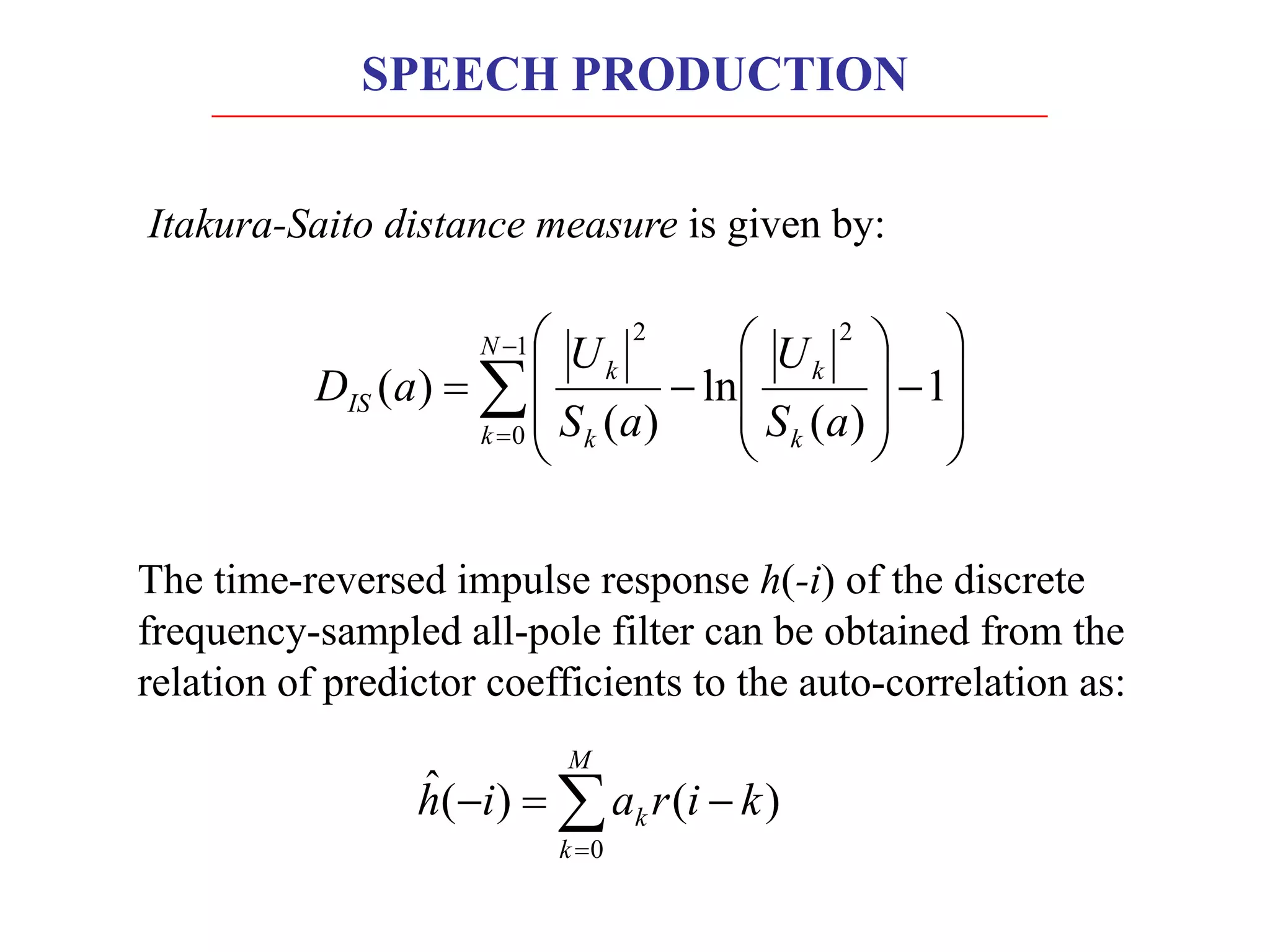
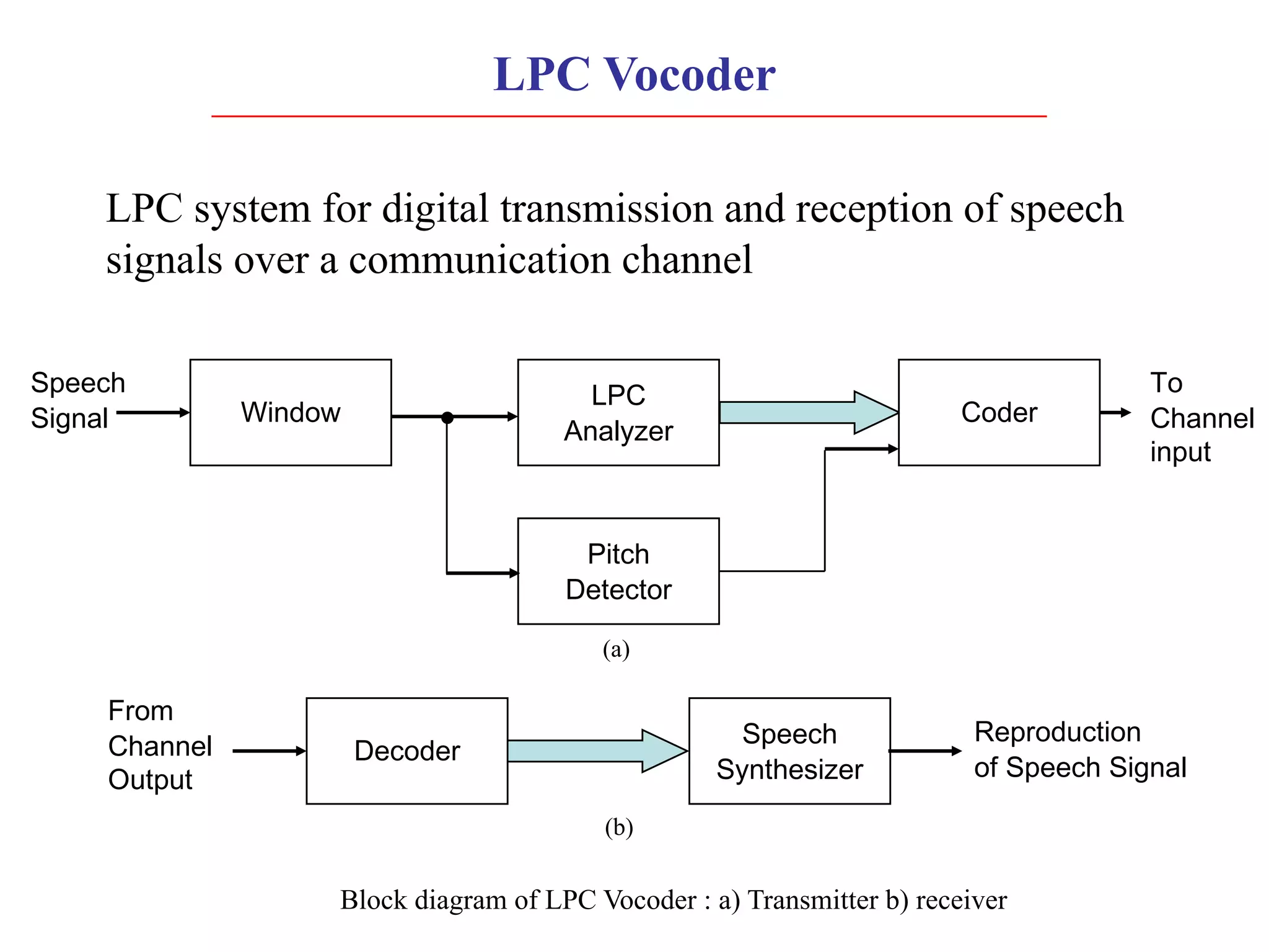
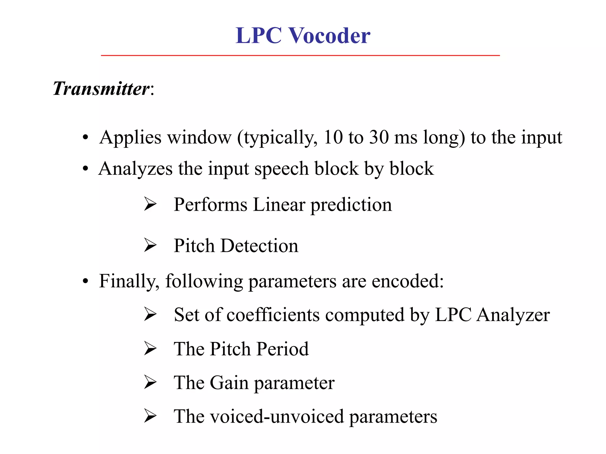
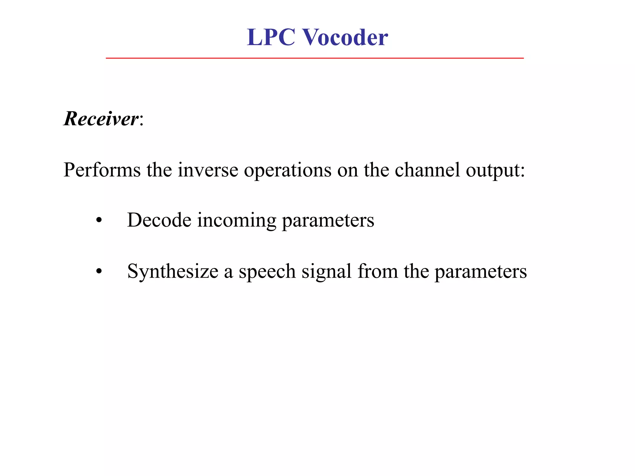
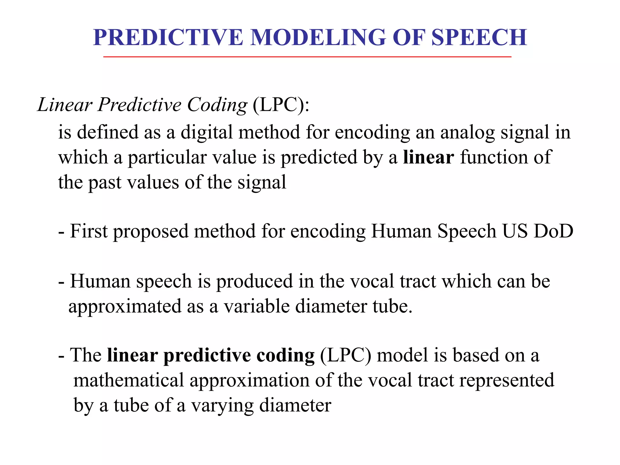
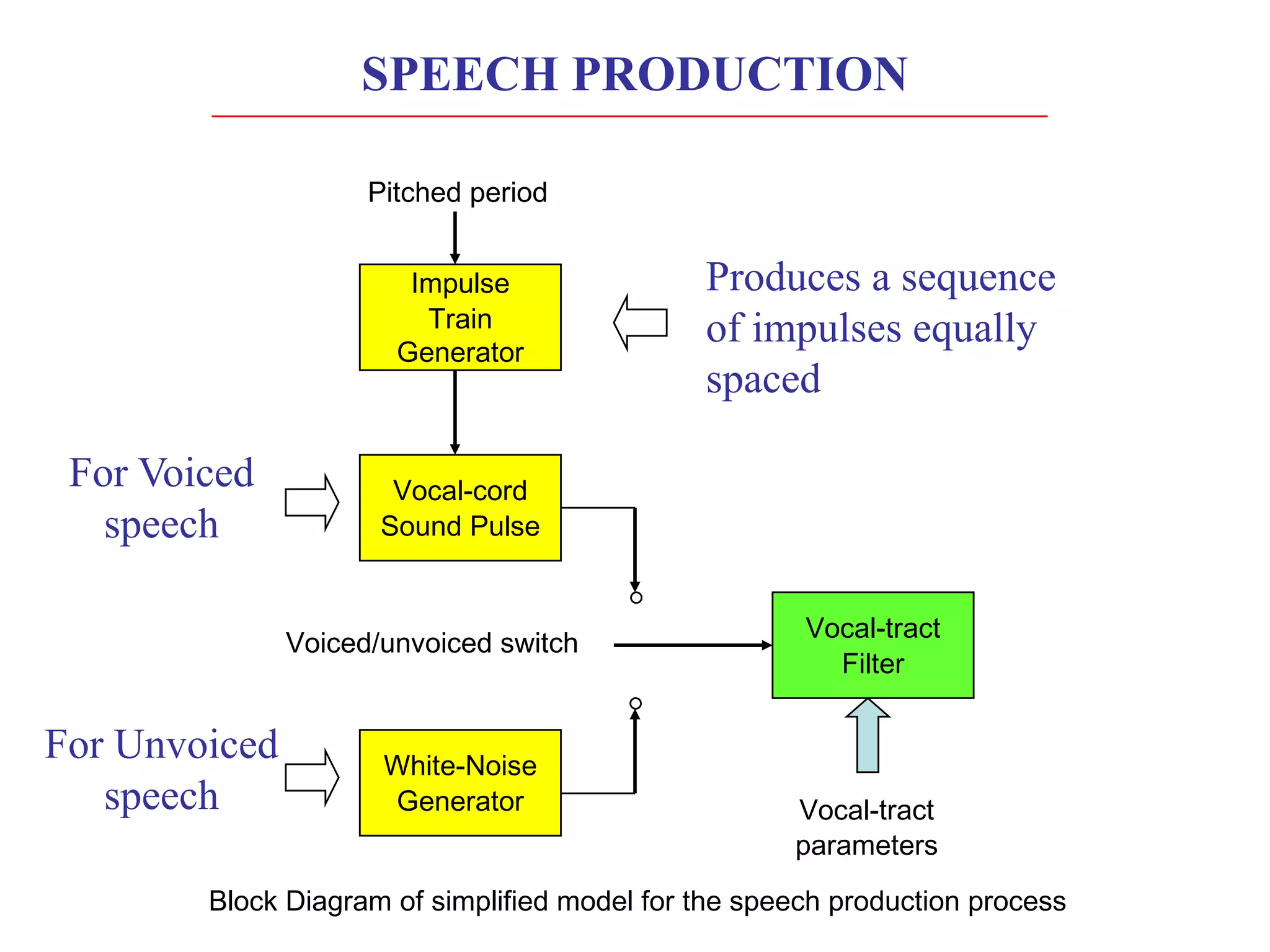
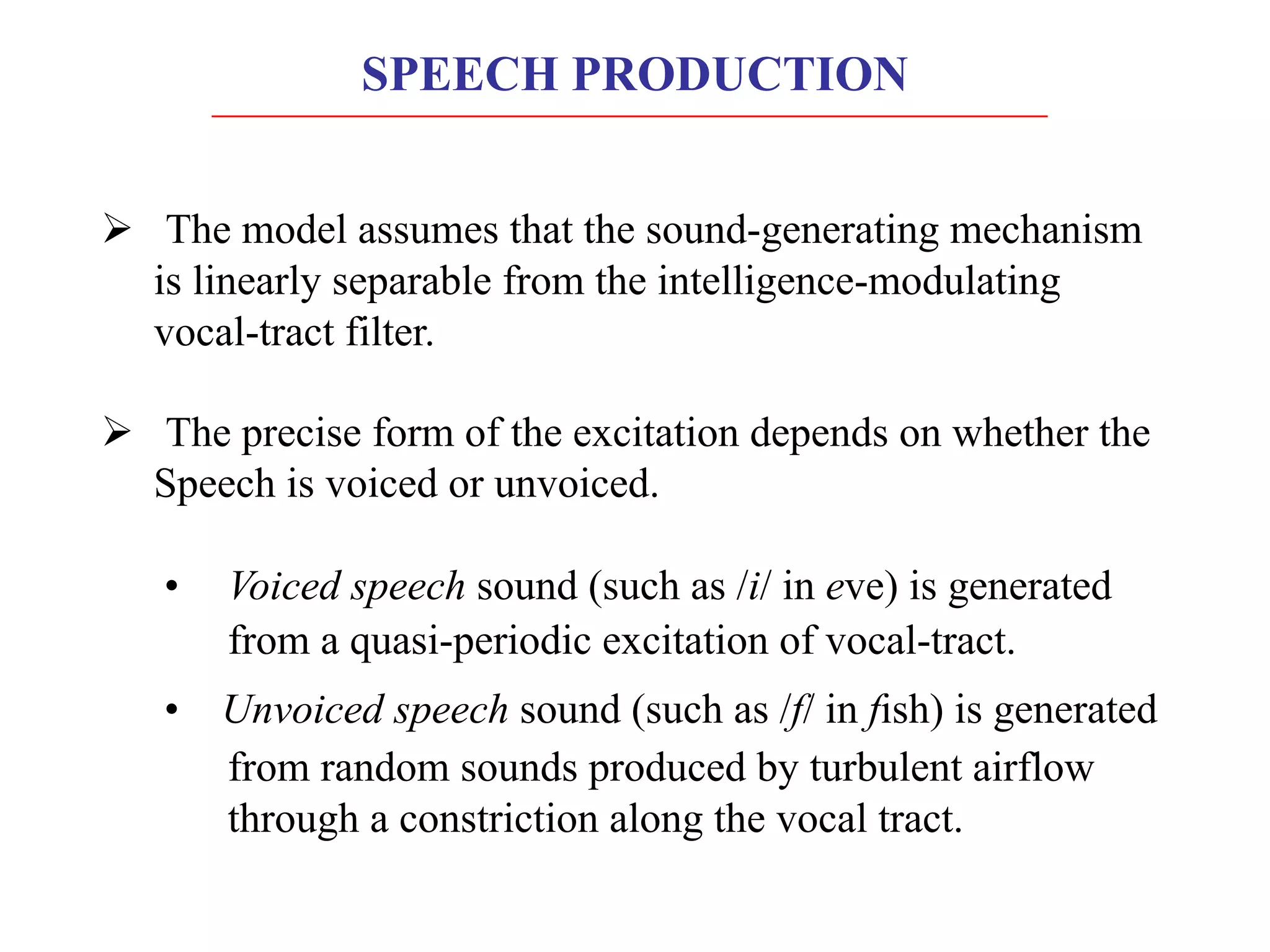
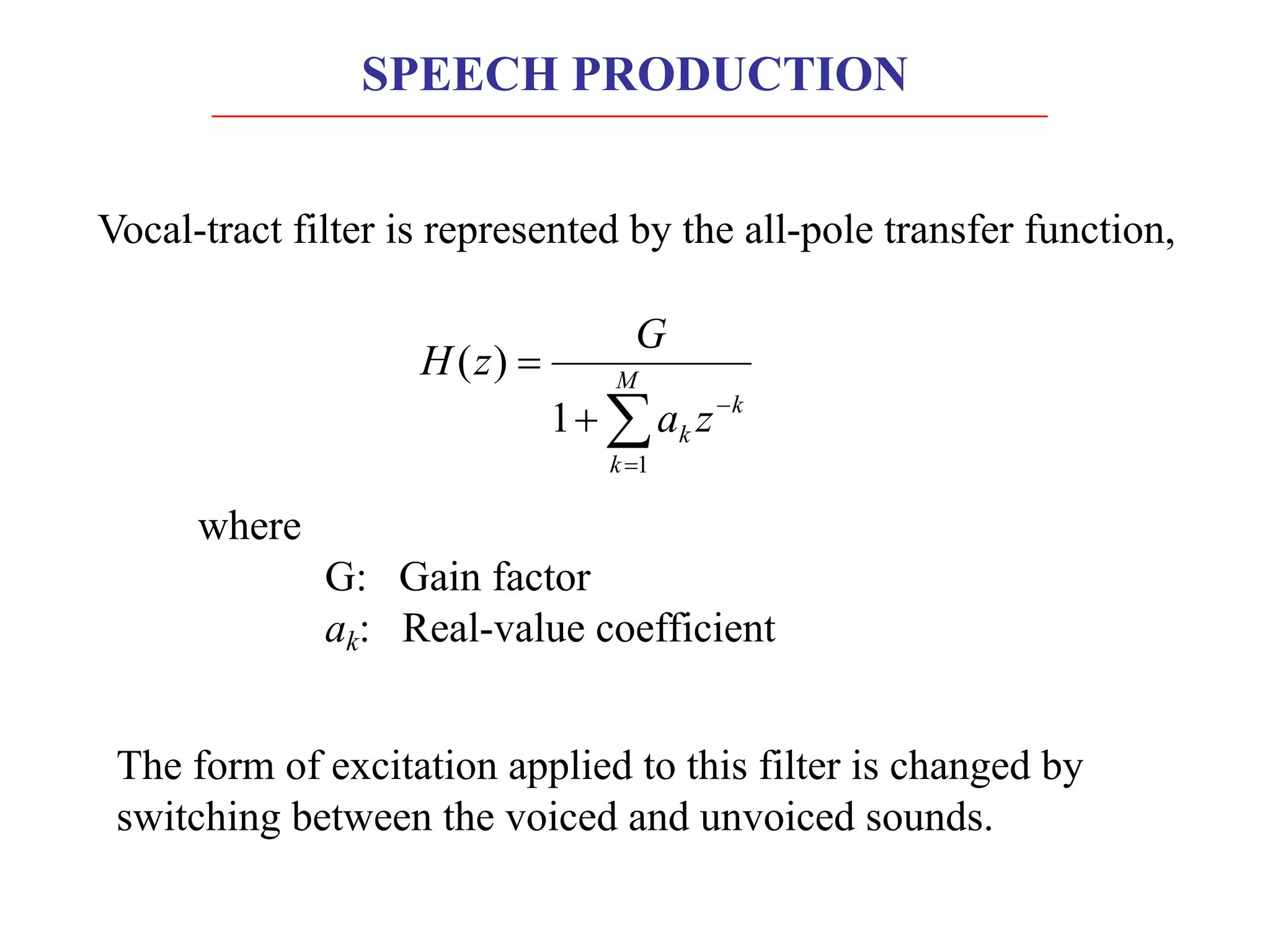
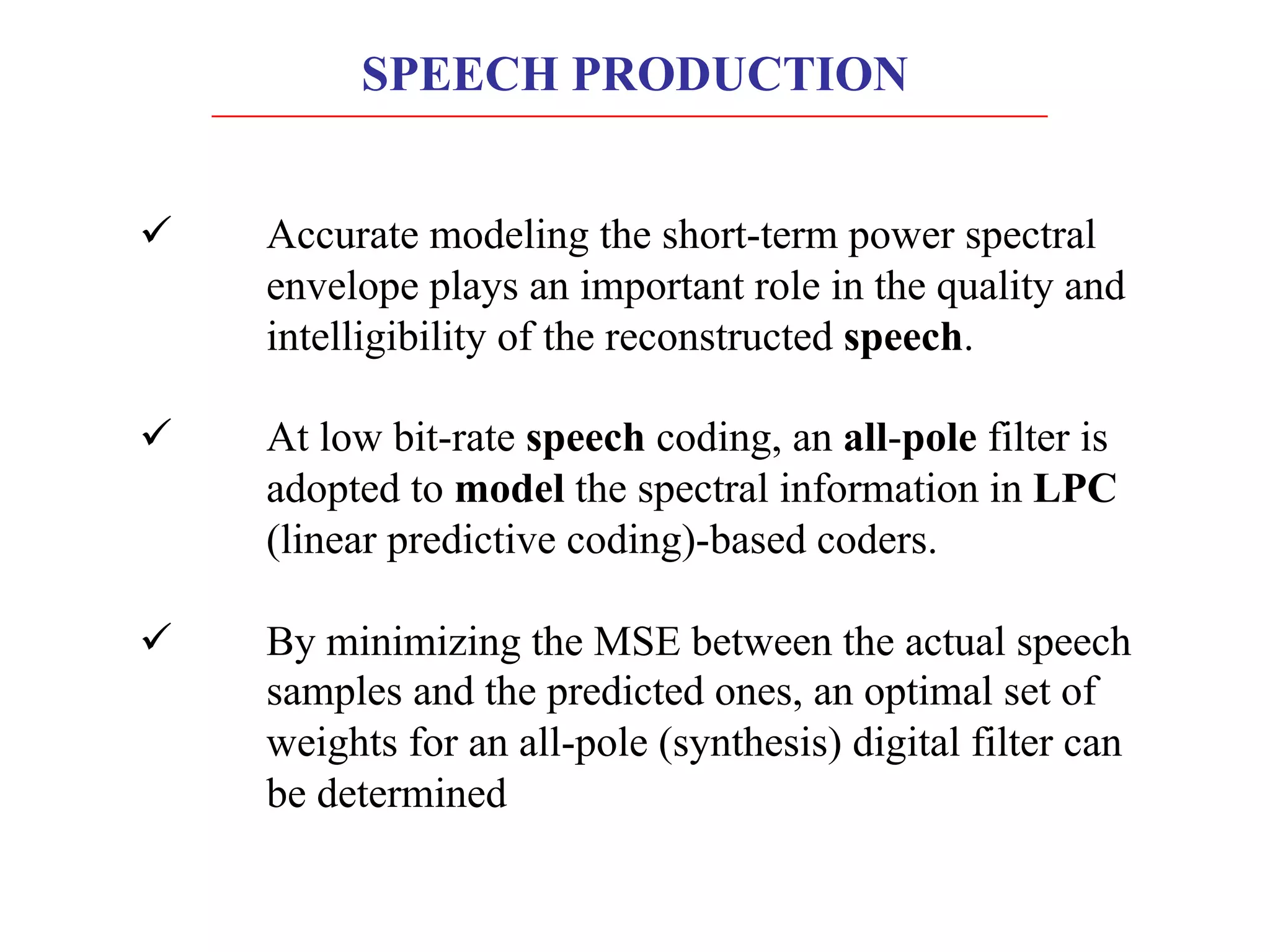
Linear predictive coding (LPC) models human speech production as a vocal tract represented by a tube of varying diameter. LPC is a digital encoding method that predicts signal values using a linear function of past values. The speech production process can be modeled as excitation of the vocal tract filter by either a periodic source for voiced sounds or random noise for unvoiced sounds. Accurately modeling the short-term power spectral envelope plays an important role in speech quality and intelligibility. The Itakura-Saito distance measure is an error criterion used in LPC that better models periodic signals like voiced speech. An LPC vocoder separates speech into parameters at the transmitter and re synthesizes speech from the parameters at the receiver.
![Let vector a denote a set of spectral parameters as:
T
M
a
a
a ]
,.....,
,
[
a 2
1
=
Note: See p.no.189-191 in textbook for proof
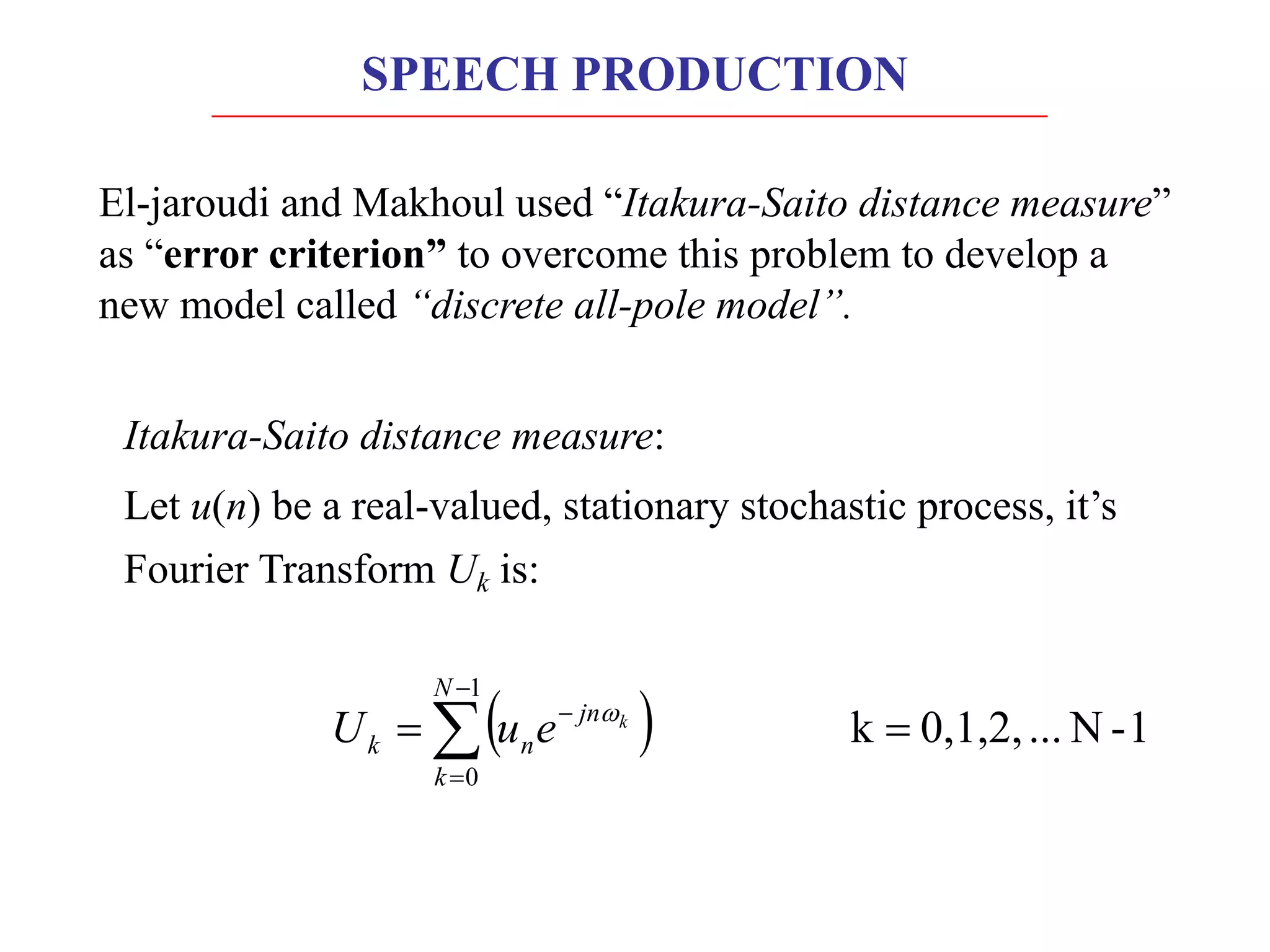
The auto-correlation function of u(n) for lag m is:
( )
( ) 1
-
N
...
0,1,2,
k
)
(
where
1
-
N
...
0,1,2,
k
1
)
(
1
0
1
0
=
=
=
=
å
å
-
=
-
-
=
N
k
jn
k
N
k
jn
k
k
k
e
m
r
S
e
S
N
m
r
w
w
SPEECH PRODUCTION](https://image.slidesharecdn.com/p4predictivemodelingspeech-230102174927-61b102bb/75/P4_Predictive_Modeling_Speech-pdf-10-2048.jpg)