OCEAN THERMAL ENERGY
OCEANTHERMAL ENERGY
CONVERSION
CONVERSION
Presented by,
Presented by,
NAVANEETHA KRISHNAN .R
NAVANEETHA KRISHNAN .R
SABARIGIRISH.G
SABARIGIRISH.G
SAI LAVANYA.S
SAI LAVANYA.S
2.
OCEAN THERMAL ENERGY
OCEANTHERMAL ENERGY
CONVERSION
CONVERSION
Presented by,
Presented by,
NAVANEETHA KRISHNAN .R
NAVANEETHA KRISHNAN .R
SABARIGIRISH.G
SABARIGIRISH.G
SAI LAVANYA.S
SAI LAVANYA.S
3.
What is OTEC?
•Manifestation of solar energy
• Top layers of ocean receive solar heating
• Bottom layers receive water from polar regions
• Natural temperature gradient
• Use in Thermodynamic cycle – Generate electricity
4.
INVENTION
INVENTION
1.
1. Georges Claudewho actually built
Georges Claude who actually built
The first OTEC plant, in Cuba in 1930.
The first OTEC plant, in Cuba in 1930.
The system generated 22 kW of
The system generated 22 kW of
electricity with a low-pressure
electricity with a low-pressure
turbine.
turbine.
2.
2. 1970 the Tokyo Electric Power
1970 the Tokyo Electric Power
Company successfully built and
Company successfully built and
deployed a 100 kW closed-cycle OTEC
deployed a 100 kW closed-cycle OTEC
plant on the island of Nauru.
plant on the island of Nauru.
5.
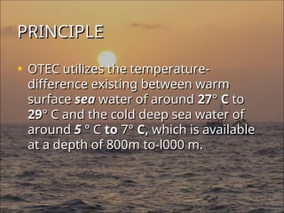
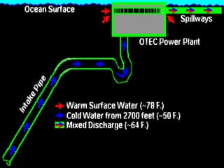
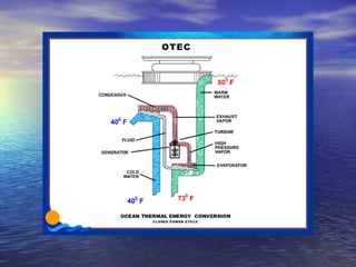
PRINCIPLE
PRINCIPLE
• OTEC utilizesthe temperature-
OTEC utilizes the temperature-
difference existing between warm
difference existing between warm
surface
surface sea
sea water of around
water of around 27
27°
° C
C to
to
29
29°
° C and the cold deep sea water of
C and the cold deep sea water of
around
around 5
5 ° C
° C to
to 7
7°
° C,
C, which is available
which is available
at a depth of 800m to-l000 m.
at a depth of 800m to-l000 m.
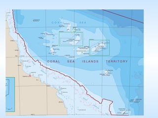
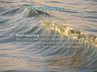
PLANT LOCATION
PLANT LOCATION
1.
1.Land based
Land based - Favoured locations : narrow shelves
- Favoured locations : narrow shelves
(volcanic islands), steep (15-20 deg) offshore
(volcanic islands), steep (15-20 deg) offshore
slopes, and relatively smooth sea floors.
slopes, and relatively smooth sea floors.
2.
2. Shelf mounted
Shelf mounted - OTEC plants can be mounted to
- OTEC plants can be mounted to
the continental shelf at depths up to 100 meters. A
the continental shelf at depths up to 100 meters. A
shelf-mounted plant could be built in a shipyard,
shelf-mounted plant could be built in a shipyard,
towed to the site, and fixed to the sea bottom.
towed to the site, and fixed to the sea bottom.
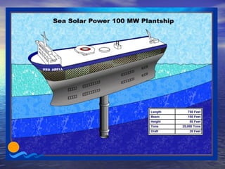
3.
3. Off shore
Off shore floating
floating plants
plants
14.
Depending on thecycle used
Depending on the cycle used
• Open cycle
Open cycle
• Closed cycle
Closed cycle
• Hybrid cycle
Hybrid cycle
• In 1979,the Natural Energy Laboratory
In 1979, the Natural Energy Laboratory
and several private-sector partners
and several private-sector partners
developed the mini OTEC experiment,
developed the mini OTEC experiment,
which achieved the first successful at-
which achieved the first successful at-
sea production of net electrical power
sea production of net electrical power
from closed-cycle OTEC.
from closed-cycle OTEC.
20.
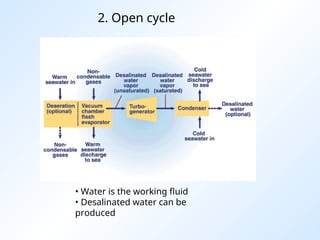
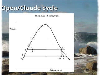
2. Open cycle
•Water is the working fluid
• Desalinated water can be
produced
21.
Open cycle
Open cycle
•This method has the advantage of
This method has the advantage of
producing desalinized fresh water,
producing desalinized fresh water,
suitable for drinking water or irrigation.
suitable for drinking water or irrigation.
22.
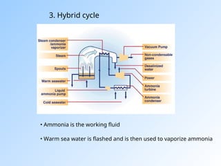
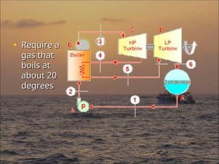
3. Hybrid cycle
•Ammonia is the working fluid
• Warm sea water is flashed and is then used to vaporize ammonia
23.
Classification
Classification
OTEC systems canbe classified as two
OTEC systems can be classified as two
types based on the thermodynamic
types based on the thermodynamic
cycle
cycle
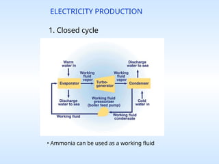
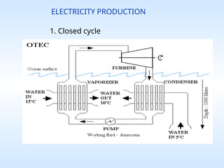
• (1) Closed cycle and
(1) Closed cycle and
• (2) Open cycle.
(2) Open cycle.
24.
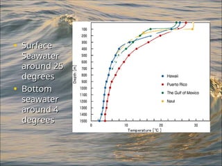
Variation of ocean
Variationof ocean
temperature with depth
temperature with depth
• The total insolation received by the
The total insolation received by the
oceans = (5.457 × 10
oceans = (5.457 × 10¹⁸
18
MJ/yr) × 0.7 = 1.9
MJ/yr) × 0.7 = 1.9
× 10
× 1018
18
MJ/yr.
MJ/yr.
(taking an average clearness index of 0.5)
(taking an average clearness index of 0.5)
Only 15% of this energy is retained as
Only 15% of this energy is retained as
thermal energy.
thermal energy.
25.
Lambert's law toquantify the
Lambert's law to quantify the
solar energy absorption by water
solar energy absorption by water
• We can use Lambert's law to quantify
We can use Lambert's law to quantify
the solar energy absorption by water,
the solar energy absorption by water,
• Y
Y the depth of water,
the depth of water,
• I
I intensity and
intensity and
• μ
μ the absorption coefficient
the absorption coefficient
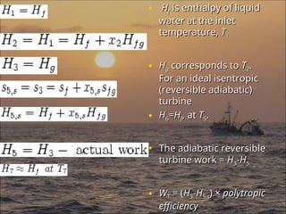
• H
Hf
f isenthalpy of liquid
is enthalpy of liquid
water at the inlet
water at the inlet
temperature,
temperature, T
T1
1
• H
Hg
g corresponds to
corresponds to T
T2
2.
.
For an ideal isentropic
For an ideal isentropic
(reversible adiabatic)
(reversible adiabatic)
turbine
turbine
• H
H6
6=
=H
Hf
f, at
, at T
T5
5.
.
• The adiabatic reversible
The adiabatic reversible
turbine work =
turbine work = H
H3
3-
-H
H5,
5,
• W
WT
T = (
= (H
H3
3-
-H
H5,
5,s
s) ×
) × polytropic
polytropic
efficiency
efficiency
30.
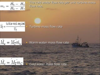
• The coldwater flow rate
The cold water flow rate per
per unit turbine mass
unit turbine mass
flow rate,
flow rate,
• Turbine mass flow rate
Turbine mass flow rate
• Warm water mass flow rate
Warm water mass flow rate
• Cold water mass flow rate
Cold water mass flow rate
31.
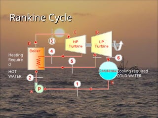
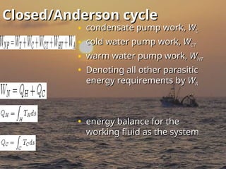
Closed/Anderson cycle
Closed/Anderson cycle
•condensate pump work,
condensate pump work, W
WC
C
• cold water pump work,
cold water pump work, W
WCT
CT
• warm water pump work,
warm water pump work, W
WHT
HT
• Denoting all other parasitic
Denoting all other parasitic
energy requirements by
energy requirements by W
WA
A
• energy balance for the
energy balance for the
working fluid as the system
working fluid as the system
32.
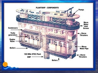
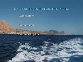
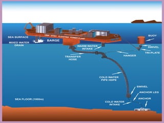
MAIN COMPONENTS OFAN OTEC SYSTEM
MAIN COMPONENTS OF AN OTEC SYSTEM
• Evaporators
Evaporators
• Condensers
Condensers
• Cold-water pipe
Cold-water pipe
• Turbines
Turbines
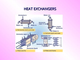
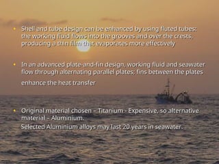
• Shell andtube design can be enhanced by using fluted tubes:
Shell and tube design can be enhanced by using fluted tubes:
the working fluid flows into the grooves and over the crests,
the working fluid flows into the grooves and over the crests,
producing a thin film that evaporates more effectively
producing a thin film that evaporates more effectively
• In an advanced plate-and-fin design, working fluid and seawater
In an advanced plate-and-fin design, working fluid and seawater
flow through alternating parallel plates; fins between the plates
flow through alternating parallel plates; fins between the plates
enhance the heat transfer
enhance the heat transfer
• Original material chosen – Titanium - Expensive, so alternative
Original material chosen – Titanium - Expensive, so alternative
material – Aluminium.
material – Aluminium.
Selected Aluminium alloys may last 20 years in seawater.
Selected Aluminium alloys may last 20 years in seawater.
35.
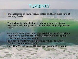
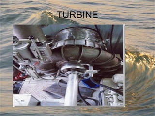
TURBINES
TURBINES
• Characterized bylow pressure ratios and high mass flow of
Characterized by low pressure ratios and high mass flow of
working fluids.
working fluids.
• The turbine is to be designed to have a good isentropic
The turbine is to be designed to have a good isentropic
expansion efficiency over a considerable range of pressure
expansion efficiency over a considerable range of pressure
ratio
ratio
For a 1 MW OTEC plant, a 4-stage axial flow reaction turbine
For a 1 MW OTEC plant, a 4-stage axial flow reaction turbine
coupled to a synchronous generator through 2 : 1 speed
coupled to a synchronous generator through 2 : 1 speed
reduction gear box is chosen.
reduction gear box is chosen.
For a considerable range of pressure ratios the turbine
For a considerable range of pressure ratios the turbine
efficiency remains above
efficiency remains above 0.85
0.85.
.
For 100 MW – low speed 200 rpm unit around 45 m in dia.
For 100 MW – low speed 200 rpm unit around 45 m in dia.
36.
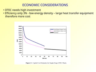
ECONOMIC CONSIDERATIONS
• OTECneeds high investment
• Efficiency only 3% - low energy density – large heat transfer equipment
therefore more cost
37.
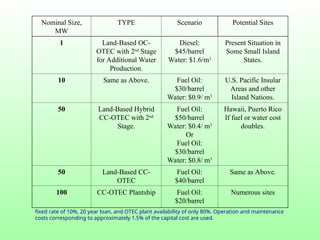
Nominal Size,
MW
TYPE ScenarioPotential Sites
1 Land-Based OC-
OTEC with 2nd
Stage
for Additional Water
Production.
Diesel:
$45/barrel
Water: $1.6/m3
Present Situation in
Some Small Island
States.
10 Same as Above. Fuel Oil:
$30/barrel
Water: $0.9/ m3
U.S. Pacific Insular
Areas and other
Island Nations.
50 Land-Based Hybrid
CC-OTEC with 2nd
Stage.
Fuel Oil:
$50/barrel
Water: $0.4/ m3
Or
Fuel Oil:
$30/barrel
Water: $0.8/ m3
Hawaii, Puerto Rico
If fuel or water cost
doubles.
50 Land-Based CC-
OTEC
Fuel Oil:
$40/barrel
Same as Above.
100 CC-OTEC Plantship Fuel Oil:
$20/barrel
Numerous sites
fixed rate of 10%, 20 year loan, and OTEC plant availability of only 80%. Operation and maintenance
costs corresponding to approximately 1.5% of the capital cost are used.
38.
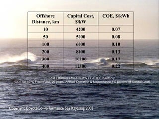
Offshore
Distance, km
Capital Cost,
$/kW
COE,$/kWh
10 4200 0.07
50 5000 0.08
100 6000 0.10
200 8100 0.13
300 10200 0.17
400 12300 0.22
Cost Estimates for 100 MW CC-OTEC Plantship
(COE for 10 % Fixed Rate, 20 years, Annual Operation & Maintenance 1% percent of Capital Cost).
39.
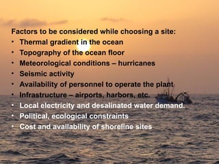
Factors to beconsidered while choosing a site:
• Thermal gradient in the ocean
• Topography of the ocean floor
• Meteorological conditions – hurricanes
• Seismic activity
• Availability of personnel to operate the plant
• Infrastructure – airports, harbors, etc.
• Local electricity and desalinated water demand.
• Political, ecological constraints
• Cost and availability of shoreline sites
40.
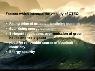
Factors which increasethe viability of OTEC:
• Rising price of crude oil, declining supplies
• Ever-rising energy demand
• Stringent regulations over emission of green
house and toxic gases
• Need for renewable source of baseload
electricity
• Energy security
41.
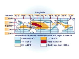
POTENTIAL
• Equatorial, tropicaland sub-tropical regions i.e.
20 °N to 20 °S, have favorable temperature profile
• Total estimated potential – 577000 MW
• 99 nations and territories have access to the
OTEC thermal resource:
Americas—Mainland - 15
Americas—Island - 23
Africa—Mainland - 18
Africa—Island - 5
Indian/Pacific Ocean—Mainland - 11
Indian/Pacific Ocean—Island - 27
43.
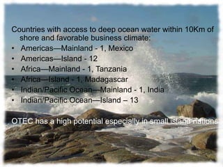
Countries with accessto deep ocean water within 10Km of
shore and favorable business climate:
• Americas—Mainland - 1, Mexico
• Americas—Island - 12
• Africa—Mainland - 1, Tanzania
• Africa—Island - 1, Madagascar
• Indian/Pacific Ocean—Mainland - 1, India
• Indian/Pacific Ocean—Island – 13
OTEC has a high potential especially in small island nations
44.
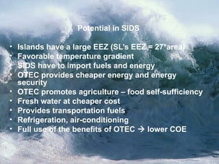
Potential in SIDS
•Islands have a large EEZ (SL’s EEZ = 27*area)
• Favorable temperature gradient
• SIDS have to import fuels and energy
• OTEC provides cheaper energy and energy
security
• OTEC promotes agriculture – food self-sufficiency
• Fresh water at cheaper cost
• Provides transportation fuels
• Refrigeration, air-conditioning
• Full use of the benefits of OTEC lower COE
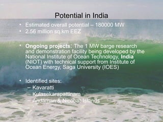
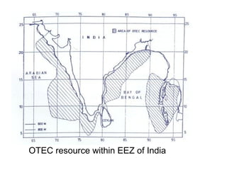
Potential in India
•Estimated overall potential – 180000 MW
• 2.56 million sq.km EEZ
• Ongoing projects: The 1 MW barge research
and demonstration facility being developed by the
National Institute of Ocean Technology, India
(NIOT) with technical support from Institute of
Ocean Energy, Saga University (IOES)
• Identified sites:
– Kavaratti
– Kulasekarapattinam
– Andaman & Nicobar Islands
OTEC R&D historyin India
1980 - Conceptual studies on OTEC plants initiated.
1984 - preliminary design for a 1 MW (gross) closed Rankine Cycle
floating plant was prepared by IITM
1993 – NIOT formed
1997 – Government proposed the establishment of the 1 MW plant
NIOT signed a memorandum of understanding with Saga
University in Japan for the joint development of the plant near
the port of Tuticorin
Goals:
The objective is to demonstrate the OTEC plant for one year, after
which it could be moved to the Andaman & Nicobar Islands for power
generation. NIOT’s plan is to build 10-25 MW shore-mounted power
plants in due course by scaling-up the 1 MW test plant, and possibly a
100 MW range of commercial plants thereafter.
49.
Floating OTEC plantconstructed in India in
2000
India piloted a 1 MW floating OTEC plant
near Tamil Nadu. Its government continues
to sponsor various research in developing
floating OTEC facilities.
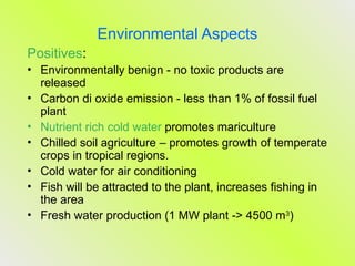
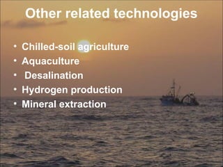
Environmental Aspects
Positives:
• Environmentallybenign - no toxic products are
released
• Carbon di oxide emission - less than 1% of fossil fuel
plant
• Nutrient rich cold water promotes mariculture
• Chilled soil agriculture – promotes growth of temperate
crops in tropical regions.
• Cold water for air conditioning
• Fish will be attracted to the plant, increases fishing in
the area
• Fresh water production (1 MW plant -> 4500 m3
)
56.
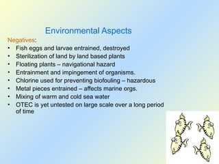
Environmental Aspects
Negatives:
• Fisheggs and larvae entrained, destroyed
• Sterilization of land by land based plants
• Floating plants – navigational hazard
• Entrainment and impingement of organisms.
• Chlorine used for preventing biofouling – hazardous
• Metal pieces entrained – affects marine orgs.
• Mixing of warm and cold sea water
• OTEC is yet untested on large scale over a long period
of time
57.
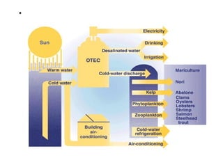
Commercial benefits ofOTEC
• Helps produce fuels such as hydrogen, ammonia, and
methanol
• Produces baseload electrical energy
• Produces desalinated water for industrial, agricultural,
and residential uses
• Provides air-conditioning for buildings
• Provides moderate-temperature refrigeration
• Has significant potential to provide clean, cost-effective
electricity for the future.
• Specially beneficial for small islands as they can become
self-sufficient
58.
• Promotes competitivenessand international trade
• Enhances energy independence and energy security
• Promotes international sociopolitical stability
• Has potential to mitigate greenhouse gas emissions
resulting from burning fossil fuels.
59.
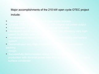
Major accomplishments ofthe 210 kW open cycle OTEC project
include:
• First net power production from open-cycle process
• Largest OTEC plant yet operated, with largest net power output
• 10 ft diameter, 7.5 ton turbine rotated at 1800 rpm
• Developed use of magnetic bearings for high efficiency very high
speed (to 48,000 rpm) vacuum pumps
• Developed and utilized flexible PC-based monitoring and control
system
• Demonstrated very high condenser efficiency from structured-
packing
design
• Successfully demonstrated about 7000 gal/day fresh water
production with minimal power loss from an auxiliary vapor to liquid
surface condenser
60.
• OTEC istechnically feasible and economically
favorable
• Mature technology
• Benefits ecology
• More plants of capacity similar to experimental
plants can be constructed